- 2011 Dodge Durango Owners Manuals
- Dodge Durango Owners Manuals
- 2008 Dodge Durango Owners Manuals
- Dodge Durango Owners Manuals
- 2009 Dodge Durango Owners Manuals
- Dodge Durango Owners Manuals
- 2007 Dodge Durango Owners Manuals
- Dodge Durango Owners Manuals
- 2004 Dodge Durango Owners Manuals
- Dodge Durango Owners Manuals
- 2013 Dodge Durango Owners Manuals
- Dodge Durango Owners Manuals
- 2005 Dodge Durango Owners Manuals
- Dodge Durango Owners Manuals
- 2006 Dodge Durango Owners Manuals
- Dodge Durango Owners Manuals
- 2012 Dodge Durango Owners Manuals
- Dodge Durango Owners Manuals
- Download PDF Manual
-
MSG or INFO Button (CD Mode for MP3 Play) Press and MSG or INFO button while playing MP3 disc. The radio scrolls through the following TAG information: Song Title, Artist, File Name, and Folder Name (if avail- able). Press the MSG or INFO button once more to return to ⬙elapsed time⬙ priority mode. Press and hold the MSG or INFO button while in the message display priority mode or elapsed time display priority mode will display the song title for each file. RW/FF (CD Mode for MP3 Play) Press the FF side of the button to move forward through the MP3 selection. TUNE Control (CD Mode for MP3 Play) Pressing the TUNE Control allows the adjustment of Tone, Balance, and Fade.
INSTRUMENT PANEL AND CONTROLS 213
AM/FM Button (CD Mode for MP3 Play) Switches back to Radio mode. RND/ PTY Button (CD Mode for MP3 Play) Pressing this button plays files randomly. SET/DIR Button (CD Mode for MP3 Play) Press the SET/DIR Button to display folders, when playing an MP3 discs that have a file/folder structure. Turn the TUNE control to display available folders or move through available folders. Press the TUNE control to select a folder. Buttons 1 - 6 (CD Mode for MP3 Play) Selects disc positions 1 - 6 for Play/Load/Eject.
214 INSTRUMENT PANEL AND CONTROLS
Operating Instructions - Hands Free Phone (If Equipped) Refer to Hands Free Phone in Section 3 of the Owner’s Manual. Operating Instructions - Satellite Radio Mode (If Equipped) Refer to the Satellite Radio section of Manual. Operating Instructions - Video Entertainment System (VES威) (If Equipped) Refer to separate Video Entertainment System (VES威) Guide.
the Owner’s
SALES CODE REC — AM/FM/CD (6–DISC) RADIO WITH NAVIGATION SYSTEM
REC Radio
Satellite Navigation Radio with CD Player with MP3
Capability (REC) combines a Global-Positioning System-based navigation system with an integrated color screen to provide maps, turn identification, selectionmenus and instructions for selecting a variety of destina- tions and routes, AM/FM stereo radio and six-disc CD changer with MP3 capability. Mapping information for navigation is supplied on a DVD that is loaded into the unit. One map DVD covers all of North America. Refer to your “Navigation User’s Manual” for detailed operating instructions. Operating Instructions — Satellite Radio (If Equipped) Refer to your “Navigation User’s Manual” for detailed operating instructions. Clock Setting Procedure
Refer to “Setting the Clock” under ”System Settings” in your Navigation User’s Manual for details about setting the clock.
INSTRUMENT PANEL AND CONTROLS 215
VIDEO ENTERTAINMENT SYSTEM (SALES CODE XRV) — IF EQUIPPED The optional VES™ (Video Entertainment System) con- sists of a DVD player and LCD (liquid crystal display) screen, a battery-powered remote control, and two head- sets. The system is located in the headliner behind the front row seat. Refer to your VES™ User’s Manual for detailed operating instructions.
SATELLITE RADIO — IF EQUIPPED Satellite radio uses direct satellite to receiver broadcast- ing technology to provide clear digital sound, coast to coast. The subscription service provider is Sirius™ Satel- lite Radio. This service offers over 100 channels of music, sports, news, entertainment, and programming for chil- dren, directly from its satellites and broadcasting studios.
216 INSTRUMENT PANEL AND CONTROLS
System Activation
NOTE: Your vehicle’s radio must be on and in satellite mode when the activation process takes place. To activate your Sirius Satellite Radio service, call the toll-free number 888-539-7474, or visit the Sirius web site at www.sirius.com. Please have the following informa- tion available when activating your system: 1. The Electronic Serial Number/Sirius Identification Number (ESN/SID). 2. Credit card information. 3. Your Vehicle Identification Number.
Electronic Serial Number/Sirius Identification Number (ESN/SID) The Electronic Serial Number/Sirius Identification Num- ber is needed to activate your Sirius Satellite Radio system. To access the ESN/SID, refer to the following steps: ESN/SID Access With REF Radios With the ignition switch in the ACCESSORY position and the radio OFF, press the CD Eject and Time buttons simultaneously for 3 seconds. The first four digits of the twelve-digit ESN/SID number will be displayed. Press the SEEK UP button to display the next four digits. Continue to press the SEEK UP button until all twelve ESN/SID digits have been displayed. The SEEK DOWN will page down until the first four digits are displayed. The radio will exit the ESN/SID mode when any other button is pushed, the ignition is turned OFF, or 5 minutes has passed since any button was pushed.
ESN/SID Access With RAQ and RAK Radios With the ignition switch in the ACCESSORY position and the radio OFF, press the CD Eject and TIME buttons simultaneously for 3 seconds. All twelve ESN/SID num- bers will be displayed. The radio will exit the ESN/SID mode when any other button is pushed, the ignition is turned OFF, or 5 minutes has passed since any button was pushed. ESN/SID Access With REC Navigation Radios Please refer to your Navigation User’s Manual. With the ignition in the ACCESSORY position and the radio off, press the CD Eject and Set buttons simulta- neously until the 12 digits of the ESN/SID appear on the screen.
INSTRUMENT PANEL AND CONTROLS 217
Selecting Satellite Mode in REF, RAQ, and RAK Radios
Selecting Satellite Mode — REF Radio Press the MODE button repeatedly until the word ⬙SAT⬙ appears in the display. A CD may remain in the radio while in the Satellite radio mode. Selecting Satellite Mode — RAQ and RAK Radio Press the MODE button repeatedly until the word ⬙SAT⬙ appears in the display. These radios will also display the current station name and program type. For more information such as song title and artist press the MSG or INFO button. A CD or tape may remain in the radio while in the Satellite radio mode.
218 INSTRUMENT PANEL AND CONTROLS
Selecting a Channel Press and release the SEEK or TUNE knob to search for the next channel. Press the top of the button to search up and the bottom of the button to search down. Holding the TUNE button causes the radio to bypass channels until the button is released. Press and release the SCAN button (if equipped) to automatically change channels every 7 seconds. The radio will pause on each channel for 7 seconds before moving on to the next channel. The word ⬙SCAN⬙ will appear in the display between each channel change. Press the SCAN button a second time to stop the search. NOTE: Channels that may contain objectionable content can be blocked. Contact Sirius Customer Care at 888-539- 7474 to discuss options for channel blocking or unblock- ing. Please have your ESN/SID information available.
Storing and Selecting Pre-Set Channels In addition to the 12 AM and 12 FM pre-set stations, you may also commit 12 satellite stations to push button memory. These satellite channel pre-set stations will not erase any AM or FM pre-set memory stations. Follow the memory pre-set procedures that apply to your radio. Using the PTY (Program Type) Button (if equipped) Follow the PTY button instructions that apply to your radio. PTY Button ⴖSCANⴖ When the desired program type is obtained, press the ⬙SCAN⬙ button within five seconds. The radio will play 7
seconds of the selected channel before moving to the next channel of the selected program type. Press the ⬙SCAN⬙ button a second time to stop the search. NOTE: Pressing the ⬙SEEK⬙ or ⬙SCAN⬙ button while performing a music type scan will change the channel byone and stop the search. Pressing a pre-set memory button during a music type scan, will call up the memory channel and stop the search. PTY Button ⴖSEEKⴖ When the desired program is obtained, press the ⬙SEEK⬙ button within five seconds. The channel will change to the next channel that matches the program type selected. Satellite Antenna To ensure optimum reception, do not place items on the roof around the rooftop antenna location. Metal objects placed within the line of sight of the antenna will cause decreased performance. Larger luggage items should be placed as far forward as possible. Do not place items directly on or above the antenna.
INSTRUMENT PANEL AND CONTROLS 219
structure or under a physical obstacle.
Reception Quality Satellite reception may be interrupted due to one of the following reasons. • The vehicle is parked in an underground parking • Dense tree coverage may interrupt reception in the • Driving under wide bridges or along tall buildings can • Placing objects over or too close to the antenna can
cause intermittent reception.
form of short audio mutes.
cause signal blockage.
220 INSTRUMENT PANEL AND CONTROLS
REMOTE SOUND SYSTEM CONTROLS — IF EQUIPPED The remote sound system controls are located on the rear surface of the steering wheel. Reach behind the wheel to access the switches.
The right hand control is a rocker type switch with a push button in the center. Pressing the top of the switch will increase the volume and pressing the bottom of the switch will decrease the volume. The button located in the center of the right hand control will switch modes to Radio or CD. The left hand control is a rocker type switch with a push button in the center. The function of the left hand control is different depending on which mode you are in. The following describes the left hand control operation in each mode. Radio Operation Pressing the top of the switch will SEEK up for the next listenable station and pressing the bottom of the switch will SEEK down for the next listenable station.
The button located in the center of the left hand control will tune to the next pre-set station that you have programmed in the radio pre-set push-buttons. CD Player Pressing the top of the switch once will go to the next track on the CD. Pressing the bottom of the switch once will go to the beginning of the current track or to the beginning of the previous track if it is within one second after the current track begins to play. If you press the switch up or down twice it plays the second track, three times, it will play the third, etc. The button in the center of the left hand switch changes CD’s on the 6–Disc in-dash CD changer radio. This button does not function for all other radios.
INSTRUMENT PANEL AND CONTROLS 221
COMPACT DISC MAINTENANCE To keep the compact discs in good condition, take the following precautions: 1. Handle the disc by its edge; avoid touching the surface. 2. If the disc is stained, clean the surface with a soft cloth, wiping from center to edge. 3. Do not apply paper or tape to the disc; avoid scratch- ing the disc. 4. Do not use solvents such as benzine, thinner, cleaners, or antistatic sprays. 5. Store the disc in its case after playing. 6. Do not expose the disc to direct sunlight. 7. Do not store the disc where temperatures may become too high.
222 INSTRUMENT PANEL AND CONTROLS
If you experience difficulty in playing a particu- NOTE: lar disc, it may be damaged (i.e. scratched, reflective coating removed, a hair, moisture or dew on the disc) oversized, or have theft protection encoding. Try a known good disc before considering disc player service.
RADIO OPERATION AND CELLULAR PHONES Under certain conditions, the cellular phone being On in your vehicle can cause erratic or noisy performance from your radio. This condition may be lessened or eliminated by relocating the cellular phone antenna. This condition is not harmful to the radio. If your radio performance does not satisfactorily “clear” by the repositioning of the antenna, it is recommended that the radio volume be turned down or off during cellular phone operation.
CLIMATE CONTROLS
Manual Control
The Air Conditioning and Heating System is designed to make you comfortable in all types of weather. The following describes its operation:
Air Conditioning Operation
To turn the air conditioning On or Off perform the following steps:
setting.
• Position the mode control button to the desired airflow • Set the front blower control to any desired speed. • Press the Snowflake (A/C) button which is located to the right of the temperature control slide. An indicator light on the Snowflake (A/C) button shows that the air conditioning is On. • Press the Snowflake (A/C) button a second time to
turn the air conditioning Off.
NOTE: The compressor will not engage until the engine has been running for several seconds. Slight changes in
INSTRUMENT PANEL AND CONTROLS 223
engine speed or power may be noticed when the com- pressor cycles. This is a normal occurrence since the compressor will cycle on and off to maintain comfort and improve fuel economy. Front Blower Control
The Front Blower controls the amount of air delivered to the passenger compartment. There are four blower speeds. The fan speed increases as you turn the control clock- wise. When the front blower control is turned to OFF, the blower will be turned off and the system will be positioned in recirculation mode.
224 INSTRUMENT PANEL AND CONTROLS
Front Mode Control
The mode control allows you to choose from several patterns of air distribution.
NOTE: To improve your selection choices, the system allows you to operate at intermediate positions between the major modes. These intermediate positions are iden- tified by the small dots and give an even blend of both modes.
Recirculation Mode (Panel or Bi-Level)
Select either the Panel or Bi-Level mode positions when the outside air contains smoke, odors, high humidity, or if rapid cooling of the interior is desired. This feature allows for recir- culation of interior air only, when ei- ther of these positions are selected. Air flows through the panel outlets or panel and floor outlets in these modes. Panel
Outside air flows through the outlets located in the instrument panel. These outlets can be adjusted to
direct the airflow. Bi-Level
Air flows through the outlets located in the instru- ment panel and those located on the floor.
NOTE: There is a difference in temperature between the upper and lower outlets for added comfort. The warmer air goes to the floor outlets. This feature gives improved comfort during sunny but cool conditions. Heat (Floor)
Outside air flows primarily through the floor out- lets located under the instrument panel. A small amount of air is directed through the defrost and side window demister outlets. Mix
Outside air flows in equal proportions through the floor and defroster outlet.
INSTRUMENT PANEL AND CONTROLS 225
Defrost
Outside air is primarily directed to the windshield through the defroster outlet located at the base of
the windshield and side window demist outlets. NOTE: The air conditioning compressor operates in both Mix and Defrost or a blend of these modes, even if the A/C button has not been pressed. This dehumidifies the air to help dry the windshield.
226 INSTRUMENT PANEL AND CONTROLS
Temperature Control The temperature of the air is controlled by a slide located on the top center of the control panel. Move the slide left or right to change the temperature. The blue area of the scale indicates cooler temperatures while the red area indicates warmer temperatures.
Rear Temperature Control — If Equipped
Rotating this knob left to the “REAR CONTROL” position allows the passengers in the second and third row seats to control the blower speed and temperature by means of the rear control located in the rear of the center floor console as described under “Rear Zone Control.” Rotating this knob to the “OFF” position, turns off the rear climate controls. Rotating this knob to the right of the “OFF” position allows the Driver and front passenger to control the rear blower speed, and the rear temperature using the front temperature slide. The mode, front or rear, is always controlled by the front mode control. For example: Panel
mode on the front control will give you air from the outlets in the headliner in the rear. Floor mode in the front will give you floor in the rear. Rear Window Defrosting and Rear Window Washer/Wiper See the “Rear Window Features” section of this book. Automatic Temperature Control (ATC) — If Equipped The control can be turned on by pressing the POWER button. When the control is turned on, it will be in the last mode prior to being turned off. Pressing the POWER button again will turn off the control. The control can also be turned on by pressing any button and it will display the corresponding operating mode for that button.
INSTRUMENT PANEL AND CONTROLS 227
Automatic Control The ATC system can maintain a steady comfort level in various weather conditions with a simple operation: • Select your desired temperature setting by pressing
the + or – side of the TEMP rocker switch.
228 INSTRUMENT PANEL AND CONTROLS
The ATC system uses an infrared sensor located in the overhead console to measure the temperature of the driver. Based on the sensor input, the system will auto- matically control comfort by varying the temperature, fan speed, and mode. This maintains a comfortable tempera- ture, even under changing conditions. It is important that the infrared sensor is kept clean and that objects are not blocking the sensor. It is also important that objects are not used that may scratch or damage it in any way. Level Of Automatic Control 72°F (22°C) is the recommended setting for maximum comfort for the average person, however, this may vary. NOTE: The temperature setting can be adjusted at any time without affecting automatic control operation. It is not necessary to move the temperature setting for cold or hot vehicles. The system automatically adjusts the tem- perature, mode and fan speed to provide comfort as quickly as possible.
In cold weather, the fan will not turn on in NOTE: AUTO mode until the engine coolant has warmed up sufficiently. This is indicated by the WARM UP DELAY message on the display. NOTE: The temperature can be displayed in U.S. or Metric by selecting the US/M customer programmable feature. Refer to the ⬙Overhead Console-Customer Pro- grammable Features.⬙ The mode will also be shown in the display and will change as required during automatic operation. NOTE: The system can be put into recirculate mode without affecting ATC operation. This will prevent out- side air from entering the vehicle. Use this mode to temporarily block out any outside odors, smoke, or dust.
Manual Control (ATC) You also may choose to customize your comfort by selecting the fan speed and mode manually. Pressing the fan speed button or any mode button places the system into manual operation. While in manual operation there are six fan speeds available and the choice of any mode. The airflow temperature is adjusted automatically to maintain the desired comfort level. You can adjust the temperature by pressing the + or – TEMP rocker switch. FAN Control
Use this button to regulate the amount of air deliv- ered through the system in any mode you select. Press the + or – side of the button to increase or decrease fan speed. Air Conditioning Operation
Press this button to turn on the air conditioning compressor. A snow flake symbol in the display
INSTRUMENT PANEL AND CONTROLS 229
shows that the compressor is on. Compressor operation is automatic when you press the AUTO button and no snowflake is shown. The compressor may operate at any temperature above 32°F (0°C). NOTE: The compressor will not engage until the engine has been running for several seconds. Slight changes in engine speed or power may be noticed when the com- pressor cycles. This is a normal occurrence since the compressor will cycle on and off to maintain comfort and improve fuel economy. Recirculate Button
Press this button to recirculate the air inside the vehicle. Outside air is prevented from entering the vehicle. Use this mode to temporarily block out any outside odors, smoke, dust or when
rapid cooling of the interior is required.
230 INSTRUMENT PANEL AND CONTROLS
Manual control of Recirculation is possible only in Panel, Floor, and Bi-Level modes. It will not operate in Mix, or Defrost modes. The recirculation symbol will flash three times indicating recirculation is not available in these modes. If the interior of the windows begin to fog, press NOTE: the recirculate button to return to outside air. Some conditions will cause captured interior air to fog win- dows when in recirculate mode. Panel
Outside air flows through the outlets located in the instrument panel. These outlets can be adjusted to
direct the airflow. Floor (Heat)
Outside air flows primarily through the floor out- lets located under the instrument panel. A small amount of air is directed through the defrost and side window demister outlets.
Mix
Outside air flows in equal proportions through the floor and defroster outlets.
Bi-Level
Air flows through the outlets located in the instru- ment panel and those located on the floor.
NOTE: There is a difference in temperature between the upper and lower outlets for added comfort. The warmer air goes to the floor outlets. This feature gives improved comfort during sunny but cool conditions. Defrost
Outside air is primarily directed to the windshield through the defroster outlets located at the base of
the windshield and side window demist outlets. NOTE: The air conditioning compressor operates in both Mix and Defrost or a blend of these modes, even if
the A/C snowflake button has not been pressed. This dehumidifies the air to help dry the windshield. Rear Temperature Control (ATC) The “REAR” button cycles through the following modes: Rear Control from Front This allows the driver or passenger to control the rear blower speeds using the FAN +/– rocker switch and the rear temperature using the TEMP +/– rocker switch. While in this mode, pressing the POWER button will turn the rear system off. Pressing the POWER, TEMP or FAN buttons will turn the rear system back on. NOTE: The display will show a “REAR” fan speed graph and a “REAR” temperature graph. CONTROL IN REAR This allows the passengers in the second row seats to control the blower speed and temperature by means of
INSTRUMENT PANEL AND CONTROLS 231
the rear control located in the rear of the center floor console as described under the ⬙Rear Zone Climate Control.⬙ NOTE: The display will show “CONTROL IN REAR.” REAR OFF This turns the rear system off. The control will return to the front system display after approximately 5 seconds if no buttons are pushed while in one of the rear system displays. You may also return to the front system display sooner by pushing any button except the POWER, REAR, TEMP or FAN buttons. NOTE: The display will show “REAR OFF.” Rear Window Defrosting and Rear Window Washer/Wiper See the “Rear Window Features” section of this book.
232 INSTRUMENT PANEL AND CONTROLS
Rear Zone Climate Control — If Equipped
Headliner air comes from the outlets in the headliner. Each of these outlets can be individually adjusted to direct the flow of air. Moving the air vane knobs on the outlets to one side will shut off the airflow.
The rear compartment control uses two rotary knobs: one for the temperature control and the other for the fan speed control. The mode for the rear air conditioning and heating system is always controlled by the front control unit. Fan and temperature can be controlled from the front control unit or the rear control unit.
INSTRUMENT PANEL AND CONTROLS 233
NOTE: For best operation, make sure that ventilation grilles located in the rear storage area are not obstructed by stowed articles.
Rear Rotary Blower Control The second row seat occupants have control of the rear blower speed, only when the front control unit is in the “REAR CONTROL” position or CONTROL IN REAR⬙ for ATC.⬙ The rear blower switch has an “Off” position and a range of blower speeds. Rotating the rear blower control clock- wise will increase the blower speed. Rear Rotary Temperature Control The second row seat occupants have control of the rear temperature control, only when the front control unit is in the “REAR CONTROL” position. To change the temperature in the rear of the vehicle, rotate the temperature control knob to the right or left. The blue area indicates cooler temperatures while the red area indicates warmer temperatures.
234 INSTRUMENT PANEL AND CONTROLS
Front Unit to Rear Unit Chart If the Front Control is Rear Airflow will come selected from Panel Headliner Bi-Level Headliner • Between Bi-Level Floor Bi-Level Floor Mix Defrost Operating Tips
Floor Floor Floor
Fast Cooldown For a fast cooldown, set the blower fan to the highest setting, set the mode control to the panel fresh position, press the snowflake button to turn on the air condition- ing, and drive with the windows open for the first few minutes. Once the hot air has been expelled, close the windows and set the mode selector to the Recirculation
panel or Recirculation Bi-level position. When a comfort- able condition has been reached, choose a mode position and adjust the temperature control and blower speed as necessary to maintain comfort. For high humidity condi- tions it may be necessary to remain in the Recirculation mode to maintain comfort. Window Fogging Windows will fog on the inside when the humidity inside the vehicle is high. This often occurs in mild or cool temperatures when it’s rainy or humid. In most cases turning on the Air-conditioning (pressing the snowflake button) will clear the fog. Adjust the temperature control, air direction and blower speed to maintain comfort. As the temperature gets colder it may be necessary to direct air onto the windshield by using MIX Mode position on the control. Adjust the temperature control
and blower speed to maintain comfort. Interior fogging on the windshield can be quickly removed by selecting the defrost mode. Regular cleaning of the inside of the windows with a non-filming cleaning solution (vinegar and water works very well) will help prevent contaminates (cigarette smoke, perfumes, etc.) from sticking to the windows. Contaminates increase the rate of window fogging. Summer Operation Air conditioned vehicles must be protected with a high quality antifreeze coolant during summer to provide proper corrosion protection and to raise the boiling point of the coolant for protection against overheating. A 50 % concentration is recommended.
INSTRUMENT PANEL AND CONTROLS 235
When using the air conditioner in extremely heavy traffic in hot weather especially when towing a trailer, addi- tional engine cooling may be required. If this situation is encountered, operate the transmission in a lower gear. When stopped in heavy traffic, it may be necessary to shift into NEUTRAL and press the accelerator slightly for fast idle operation. Winter Operation When operating the system during the winter months, make sure the air intake, located directly in front of the windshield, is free of ice, slush, snow, or other obstruc- tions.
236 INSTRUMENT PANEL AND CONTROLS
Operating Tips Chart
REAR WINDOW FEATURES
Rear Window Wiper/Washer
INSTRUMENT PANEL AND CONTROLS 237
A rotating switch located on the climate control panel turns the rear wiper On or Off. Pressing the rotating switch inward activates the rear window washer. Rotating the switch will enable one of five intermittent delay times for the rear wiper. The delay times range from 20 to 1 second.
238 INSTRUMENT PANEL AND CONTROLS
If the rear wiper is operating when the ignition is turned off, the wiper will automatically return to the “Park” position. When the vehicle is restarted, the wiper will resume operation. Rear Window Defrosting
A push-button type switch is located in the climate control panel. Press the switch and the rear win- dow defroster and electric remote control heated mirrors (if equipped) will turn On. An amber indicator on the push-button will light when the defroster is turned On. An symbol will be displayed when the defroster is turned on with an ATC control. Push again to turn Off prior to time-out. The defroster will automatically turn Off after fifteen minutes. For ten more minutes of operation, push the button again. To prevent excessive battery drain, use the defroster only when the engine is operating.
CAUTION!
Use care when washing the inside of the rear win- dow to prevent damage to heating elements. Use a soft cloth and a mild washing solution, wiping parallel to the heating elements. Also, keep all objects a safe distance from the window to prevent damaging the heating elements.
STARTING AND OPERATING
CONTENTS
䡵 Starting Procedures . . . . . . . . . . . . . . . . . . . . . 242
▫ Automatic Transmission . . . . . . . . . . . . . . . . 242
▫ Normal Starting . . . . . . . . . . . . . . . . . . . . . . 242
▫ Engine Block Heater — If Equipped . . . . . . . . 244
䡵 Automatic Transmission . . . . . . . . . . . . . . . . . . 245
▫ Automatic Transmission . . . . . . . . . . . . . . . . 245
䡵 Four-Wheel Drive Operation . . . . . . . . . . . . . . . 250▫ NV 144 Transfer Case Operating
Information/Precautions . . . . . . . . . . . . . . . . 250
▫ Shifting Procedure - NV 144 Transfer Case . . . 252
▫ NV 244 Generation II Transfer Case OperatingInformation / Precautions . . . . . . . . . . . . . . . 253
▫ Shifting Procedure - NV 244 Generation II
Transfer Case . . . . . . . . . . . . . . . . . . . . . . . . 256
䡵 Parking Brake . . . . . . . . . . . . . . . . . . . . . . . . . 258
䡵 Brake System . . . . . . . . . . . . . . . . . . . . . . . . . . 260
. . . 260
䡵 Power Steering . . . . . . . . . . . . . . . . . . . . . . . . 262
䡵 Rocking The Vehicle . . . . . . . . . . . . . . . . . . . . . 264▫ Four-Wheel Anti-Lock Brake System (ABS)
240 STARTING AND OPERATING
䡵 Tire Safety Information . . . . . . . . . . . . . . . . . . . 264
▫ Tire Markings . . . . . . . . . . . . . . . . . . . . . . . . 264
▫ Tire Identification Number (TIN) . . . . . . . . . . 268
▫ Tire Loading And Tire Pressure . . . . . . . . . . . 269
䡵 Tires—General Information . . . . . . . . . . . . . . . . 273
▫ Tire Pressure . . . . . . . . . . . . . . . . . . . . . . . . . 273
▫ Tire Inflation Pressures . . . . . . . . . . . . . . . . . 274
▫ Radial-Ply Tires . . . . . . . . . . . . . . . . . . . . . . 276
▫ Compact Spare Tire — If Equipped . . . . . . . . . 277
▫ Limited Use Spare — If Equipped . . . . . . . . . 278
▫ Tire Spinning . . . . . . . . . . . . . . . . . . . . . . . . 278
▫ Tread Wear Indicators . . . . . . . . . . . . . . . . . . 279
▫ Life Of Tire . . . . . . . . . . . . . . . . . . . . . . . . . 280▫ Replacement Tires . . . . . . . . . . . . . . . . . . . . . 280
▫ Alignment And Balance . . . . . . . . . . . . . . . . . 281䡵 Supplemental Tire Pressure Information – If
Equipped . . . . . . . . . . . . . . . . . . . . . . . . . . . . 282
䡵 Tire Chains . . . . . . . . . . . . . . . . . . . . . . . . . . . 282
䡵 Snow Tires . . . . . . . . . . . . . . . . . . . . . . . . . . . 283
䡵 Tire Rotation Recommendations . . . . . . . . . . . . 284
䡵 Fuel Requirements . . . . . . . . . . . . . . . . . . . . . . 285
▫ Reformulated Gasoline . . . . . . . . . . . . . . . . . 286
▫ Gasoline/Oxygenate Blends . . . . . . . . . . . . . . 286
▫ MMT In Gasoline . . . . . . . . . . . . . . . . . . . . . 287
▫ Materials Added To Fuel . . . . . . . . . . . . . . . . 287
▫ Adding Fuel . . . . . . . . . . . . . . . . . . . . . . . . . 287▫ Fuel System Cautions . . . . . . . . . . . . . . . . . . 289
▫ Carbon Monoxide Warnings . . . . . . . . . . . . . . 290
䡵 Catalytic Converter . . . . . . . . . . . . . . . . . . . . . 291
䡵 Vehicle Loading . . . . . . . . . . . . . . . . . . . . . . . . 292
▫ Certification Label . . . . . . . . . . . . . . . . . . . . . 292
▫ Curb Weight . . . . . . . . . . . . . . . . . . . . . . . . . 294
▫ Loading . . . . . . . . . . . . . . . . . . . . . . . . . . . . 294
䡵 Trailer Towing . . . . . . . . . . . . . . . . . . . . . . . . . 296
▫ Common Towing Definitions . . . . . . . . . . . . . 296
▫ Trailer Hitch Classification . . . . . . . . . . . . . . . 298
▫ Trailer Towing Weights (Maximum TrailerWeight Ratings)
. . . . . . . . . . . . . . . . . . . . . . 299
STARTING AND OPERATING 241
▫ Trailer And Tongue Weight . . . . . . . . . . . . . . 299
▫ Towing Requirements . . . . . . . . . . . . . . . . . . 300
▫ Towing Tips . . . . . . . . . . . . . . . . . . . . . . . . . 305
▫ Trailer Towing Mirrors — If Equipped . . . . . . 307
䡵 Snowplow . . . . . . . . . . . . . . . . . . . . . . . . . . . . 307
. . . . . . . . . . . . . . . . 307
䡵 Recreational Towing (Behind Motorhome, Etc.) . . 308
. . . . . . . . . 308
. . . . . . . . . 308
䡵 Traction . . . . . . . . . . . . . . . . . . . . . . . . . . . . . 312
䡵 Equipment Identification Plate . . . . . . . . . . . . . 313▫ Recreational Towing 2WD Models ▫ Recreational Towing 4WD Models
▫ Dodge Durango Models
242 STARTING AND OPERATING
STARTING PROCEDURES
Automatic Transmission Start the engine with the selector lever in NEUTRAL or PARK position. Apply the brake before shifting to any driving range.
WARNING!
Do not attempt to push or tow your vehicle to get it started. Vehicles equipped with an automatic trans- mission cannot be started this way. Unburned fuel could enter the catalytic converter and once the engine has started, ignite and damage the converter and vehicle. If the vehicle has a discharged battery, booster cables may be used to obtain a start from a booster battery or the battery in another vehicle. This type of start can be dangerous if done improperly. See section 6 of this manual for the proper jump starting procedures and follow them carefully.
Normal Starting Normal Starting of either a warm or cold engine is obtained without pumping or depressing the accelerator pedal. Tip Start Feature Your vehicle has a “Tip Start” starting system. With “Tip Start” the driver does not need to hold the key in the ’Start’ position until the vehicle starts, but can release the key (still in the ignition) and the vehicle will continue through the start cycle. • Turn the ignition key to the START position, until the • Release the key (still in the ignition) and the starter will continue through the start cycle until the vehicle starts or for 5 seconds (whichever comes first).
start motor engages.
If Engine Fails To Start If the engine fails to start after you have followed the Normal Starting procedure, it may be flooded. Push the accelerator pedal all the way to the floor and hold it there while cranking the engine. This should clear any excess fuel in case the engine is flooded.
CAUTION!
To prevent damage to the starter, do not crank the engine for more than 15 seconds at a time. Wait 10 to 15 seconds before trying again.
If the engine has been flooded, it may start to run, but not have enough power to continue running when the key is released. If this occurs, continue cranking with the accel- erator pedal pushed all the way to the floor. Release the accelerator pedal and the key once the engine is running smoothly.
STARTING AND OPERATING 243
If the engine shows no sign of starting after two 15
second periods of cranking with the accelerator pedal held to the floor, the Normal Starting procedure should be repeated.WARNING!
Never pour fuel or other flammable liquid into the throttle body air inlet opening in an attempt to start the vehicle. This could result in flash fire causing serious personal injury.
After Starting The idle speed is automatically controlled on fuel injected engines and will decrease as the engine warms up.
244 STARTING AND OPERATING
CAUTION!
Long periods of engine idling can cause excessive exhaust temperatures which can damage your ve- hicle. Do not leave your vehicle unattended with the engine running.
WARNING!
Do not leave children or animals inside parked vehicles in hot weather. Interior heat build up may cause serious injury or death.
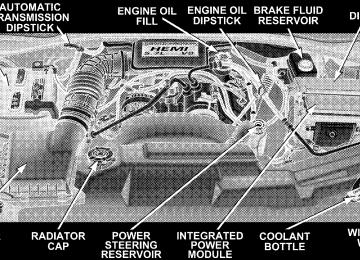
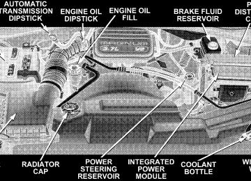
Engine Block Heater — If Equipped The engine block heater warms engine coolant and permits quicker starts in cold weather. Connect the cord to a standard 110-115 volt AC electrical outlet with a grounded, three wire extension cord. The 3.7L/4.7L engine block heater cord is located at the front of the engine compartment near the radiator cap. The 5.7L engine block heater cord is located on the left side of the engine compartment and rearward of the power distribution center.
WARNING!
Remember to disconnect the cord before driving. Damage to the 110-115 volt electrical cord could cause electrocution.
AUTOMATIC TRANSMISSION
Automatic Transmission The electronic PRNDL on the instrument cluster indicates the transmission gear selected. The selector lever is mounted on the right side of the steering column. To drive, move the selector lever from Park or Neutral to the desired drive position. Pull selector lever toward you when shifting into Reverse, Second, First or Park, or when shifting out of Park. Brake/Transmission Interlock System This system prevents you from moving the gear shift out of Park and into any gear unless the brake pedal is pressed. This system is active only while the ignition switch is in the ON position. Always depress the brake pedal first, before moving the gear selector out of PARK. Gear Ranges DO NOT race the engine when shifting from Park or Neutral position into another gear range.
STARTING AND OPERATING 245
“P” Park Supplements parking brake by locking the transmission. Engine can be started in this range. Never use Park while vehicle is in motion. Apply parking brake when leaving vehicle in this range. Always apply parking brake first, then place selector in Park position.
WARNING!
Your vehicle could move and injure you and others if it is not completely in P (Park). Check by trying to move the gearshift lever back and forth without first pulling the lever toward you, after you have set it in P (Park). Make sure it is in Park before leaving the vehicle.
246 STARTING AND OPERATING
WARNING!
Never use Park position on an automatic transmis- sion as a substitute for the parking brake. Always apply parking brake fully when parked to guard against vehicle movement and possible injury or damage.
WARNING!
It is dangerous to shift the selector lever out of “P” or “N” if the engine speed is higher than idle speed. If your foot is not firmly on the brake pedal, the vehicle could accelerate quickly forward or in re- verse. You could lose control of the vehicle and hit someone or something. Only shift into gear when the engine is idling normally and when your right foot is firmly on the brake pedal.
“R” Reverse Use this range only after the vehicle has come to a complete stop. “N” Neutral Shift to Neutral when vehicle is standing for prolonged periods with engine running. Engine may be started in this range. Set the parking brake if you must leave the vehicle. NOTE: Towing the vehicle (except as specified under Towing A Disabled Vehicle), coasting, or otherwise driv- ing the vehicle while in N (Neutral) can cause severe transmission damage “D” Drive For most city and highway driving. “2” Second For driving slowly in heavy city traffic or on mountain roads where more precise speed control is desirable. Use
it also when climbing long grades, and for engine brak- ing when descending moderately steep grades. To pre- vent excessive engine speed do not exceed 45 miles per hour (72 km/h) in this range. “1” First For driving up very steep hills and for engine braking at low speeds 25 mph (40 km/h) or less when going down hill. To prevent excessive engine speed do not exceed 25
mph (40 km/h) in this range. Overdrive Operation The overdrive automatic transmission contains an elec- tronically controlled fourth and fifth (if equipped) speed (Overdrive). The transmission will automatically shift from Drive to Overdrive if the following conditions are present: • the transmission selector is in Drive;STARTING AND OPERATING 247
perature;
• the engine coolant has reached normal operating tem- • vehicle speed is above approximately 30 mph (48
• the “TOW/HAUL” switch has not been activated; • transmission has reached normal operating tempera-km/h);
ture. If the vehicle is started in extremely cold tem- NOTE: peratures, the transmission may not shift into Overdrive and will automatically select the most desirable gear for operation at this temperature. Normal operation will resume when the transmission fluid temperature has risen to a suitable level. Refer also to the Note under torque converter clutch, later in this section.
When To Use “TOW/HAUL” Mode
248 STARTING AND OPERATING
If the transmission temperature gets extremely hot, the transmission will automatically select the most desirable gear for operation at this temperature. If the transmission temperature becomes hot enough the TRANS TEMP light may illuminate and the transmission may downshift out of Overdrive until the transmission cools down. After cooldown, the transmission will resume normal opera- tion. The transmission will downshift from Overdrive to Drive if the accelerator pedal is fully depressed at vehicle speeds above approximately 35 mph (56 km/h).
When driving in hilly areas, towing a trailer, carrying a heavy load, etc., and frequent transmission shifting oc- curs, press the “TOW/HAUL” button. This will improve performance and reduce the potential for transmission overheating or failure due to excessive shifting. When operating in “TOW/HAUL” mode, (if
5th gear
equipped) is disabled and 2-3 and 3-4 shift patterns are modified. Shifts into Overdrive (4th gear) are allowed during steady cruise (for improved fuel economy) and automatic closed-throttle downshifts to 3rd gear (for improved braking) will occur during steady braking. The “TOW/HAUL” light will illuminate in the instru- ment cluster to indicate when the switch has been activated. Pressing the switch a second time restores normal operation. If the “TOW/HAUL” mode is desired, the button must be pressed each time the engine is started. Torque Converter Clutch A feature designed to improve fuel economy is included in all automatic transmissions. A clutch within the torque converter engages automatically at a calibrated speed at light throttle. It engages at higher speeds under heavier acceleration. This may result in a slightly different feeling or response during normal operation in high gear. When
STARTING AND OPERATING 249
the
the vehicle speed drops below a calibrated speed, or during acceleration, clutch automatically and smoothly disengages. The feature is operational in Over- drive and in Drive. NOTE: The torque converter clutch will not engage until the transmission fluid and engine coolant are warm [usually after 1-3 miles (1.6 - 4.8 km) of driving]. Because the engine speed is higher when the torque converter clutch is not engaged, it may seem as if the transmission is not shifting into Overdrive when cold. This is normal. Pressing the⬙TOW/HAUL⬙ button will demonstrate that the transmission is able to shift into and out of Overdrive. If the vehicle has not been driven in several NOTE: days, the first few seconds of operation after shifting the transmission into gear may seem sluggish. This is due to the fluid partially draining from the torque converter into the transmission. This condition is normal and will not
250 STARTING AND OPERATING
cause damage to the transmission. The torque converter will refill within five seconds of shifting from Park into any other gear position.
FOUR-WHEEL DRIVE OPERATION
NV 144 Transfer Case Operating Information/Precautions The NV 144 is an electric shift transfer case and is operated by the Four-Wheel-Drive (4WD) Control Switch, which is located on the instrument panel. The NV 144 transfer case provides 2 mode positions: All-Wheel Drive (AWD) and 4-Wheel-Drive LOCK. The NV 144 transfer case is designed to be driven in for AWD for normal street and highway conditions (all road surfaces roads). When additional traction is required, the transfer case 4LOCK position can be used to lock the front and rear driveshafts together and force the front and rear wheels
to rotate at the same speed. This is accomplished by rotating the 4WD Control Switch to the 4LOCK position - see Shifting Procedure section for specific shifting instructions. The 4LOCK position is designed for loose, slippery road surfaces only. Driving in the 4LOCK posi- tion on dry hard surfaced roads may cause increased tire wear and damage to the driveline components. Transfer Case Position Indicator Lights Transfer case position indicator lights are located on the instrument cluster, and indicate the current and desired transfer case selection. If there are no indicator lights on or flashing the transfer case position is All-Wheel Drive (AWD). The “SVC 4WD” warning light monitors the electric shift 4WD system. If this light remains on after engine start up or illuminates during driving, it means that the 4WD system is not functioning properly and that service is required.
WARNING!
Always engage the parking brake when powering down the vehicle if the ⴖService 4WDⴖ light is illuminated. Not engaging the parking brake may allow the vehicle to roll which may cause personal injury.
NOTE: Do not attempt to make a shift while only the front or rear wheels are spinning. The NV 144 transfer case is not equipped with a synchronizer and therefore the front and rear driveshaft speeds must be equal for the shift to take place. Shifting while only the front or rear wheels are spinning can cause damage to the transfer case. Proper operation of four-wheel-drive vehicles depends on tires of equal size, type and circumference on each wheel. Any difference in tire size can cause damage to the transfer case.
STARTING AND OPERATING 251
Because four-wheel-drive provides improved traction, there is a tendency to exceed safe turning and stopping speeds. Do not go faster than road conditions permit. For additional information on the appropriate use of each transfer case mode position see the information below: AWD Normal All-Wheel-Drive High Range - Employs inter- axle differential. Allows front and rear wheels to rotate at different speeds. All road surfaces. 4LOCK Four-Wheel-Drive LOCK - Locks the front and rear driveshafts together. Forces the front and rear wheels to rotate at the same speed. Additional traction for loose, slippery road surfaces only.
252 STARTING AND OPERATING
Shifting Procedure - NV 144 Transfer Case
AWD to 4LOCK or 4LOCK to AWD With the key ON and the engine either OFF or RUN- NING, rotate the transfer case switch, located on the instrument panel to the desired position.
NOTE: Delayed shifting out of 4LOCK may be experi- enced due to uneven tire wear, low tire pressure, or excessive vehicle loading. If any of the requirements to select a new NOTE: transfer case position have not been met, the transfer case will not shift. The indicator light will flash and the current transfer case position will be maintained. To retry a selection, turn the control knob back to the current position, wait five (5) seconds, and retry the shift. NOTE: The 4x4 system will not allow shifts between AWD/4LOCK if the rear wheels are spinning (no trac- tion). In this situation the position indicator light will continue to flash. At this time, reduce speed and stop spinning the wheels to complete the shift. There may be a delay up to 13 seconds for the shift to complete after the wheels have stopped spinning. NOTE: The ignition key must be ON for a shift to take place and for the position indicator lights to be operable.
If the key is not ON then the shift will not take place and no position indicator lights will be on or flashing. NV 244 Generation II Transfer Case Operating Information / Precautions The NV 244 Generation II is an electric shift transfer case and is operated by the 4WD Control Switch, which is located on the instrument panel. The NV 244 Generation II transfer case provides 4 mode positions - Normal all-wheel-drive high range, four- wheel-drive LOCK, four-wheel-drive low range, and neutral. This transfer case is equipped with an inter-axle differ- ential that allows driving the vehicle in the normal all-wheel-drive position (AWD) at all times on any given road surface, including dry hard surfaced roads. The AWD mode allows the front and rear wheels to rotate at different speeds. This eliminates driveline binding and component wear normally associated with driving the
STARTING AND OPERATING 253
vehicle in the 4LOCK position on dry hard surfaced roads. This feature provides the safety, security, and convenience of operating in all-wheel drive at all times regardless of road conditions. When additional traction is required, the 4LOCK and 4LO positions can be used to lock the front and rear driveshafts together through the transfer case inter-axle differential and force the front and rear wheels to rotate at the same speed. This is accomplished by rotating the 4WD Control Switch to these positions. The 4LOCK and 4LO positions are intended for loose, slippery road surfaces only. Driving in the 4LOCK and 4LO positions on dry hard surfaced roads may cause increased tire wear and damage to the driveline components. The transfer case Neutral (N) position is selected by depressing the recessed button located on the lower left hand corner of the 4WD Control Switch.
254 STARTING AND OPERATING
NOTE: The transfer case Neutral (N) position is to be used for recreational towing only. See Recreational Tow- ing section for specific procedures on shifting into and out of Neutral (N). Transfer Case Position Indicator Lights Transfer case position indicator lights are located on the instrument cluster. If there are no indicator lights on or flashing the transfer case position is All-Wheel Drive (AWD) and indicate the current and desired transfer case selection (4HI ⇔ 4LOCK). The “SVC 4WD” warning light monitors the electric shift 4WD system. If this light remains on after engine start up or illuminates during driving, it means that the 4WD system is not functioning properly and that service is required.
WARNING!
Always engage the parking brake when powering down the vehicle if the ⴖService 4WDⴖ light is illuminated. Not engaging the parking brake may allow the vehicle to roll which may cause personal injury.
NOTE: Do not attempt to make a shift while only the front or rear wheels are spinning. The NV 244 Generation II transfer case is not equipped with a synchronizer and therefore the front and rear driveshaft speeds must be equal for the shift to take place. Shifting while only the front or rear wheels are spinning can cause damage to the transfer case.
When operating your vehicle in 4LO, the engine speed is approximately three times that of the AWD or 4LOCK positions at a given road speed. Take care not to over- speed the engine and do not exceed 40 km/h (25 mph). Proper operation of four-wheel-drive vehicles depends on tires of equal size, type and circumference on each wheel. Any difference in tire size can cause damage to the transfer case. Because four-wheel drive provides improved traction, there is a tendency to exceed safe turning and stopping speeds. Do not go faster than road conditions permit.
STARTING AND OPERATING 255
WARNING!
You or others could be injured if you leave the vehicle unattended with the transfer case in the Neutral (N) position without first fully engaging the parking brake. The transfer case Neutral (N) position disengages both the front and rear driveshafts from the powertrain and will allow the vehicle to move regardless of the transmission position. The parking brake should always be applied when the driver is not in the vehicle.
For additional information on the appropriate use of each transfer case mode position see the information below: AWD Normal All-Wheel-Drive High Range - Employs inter- axle differential. Allows front and rear wheels to rotate at different speeds. All road surfaces.
256 STARTING AND OPERATING
4LOCK Four-Wheel-Drive LOCK - Locks the transfer case inter- axle differential. Forces front and rear wheels to rotate at the same speed. Additional traction for loose, slippery road surfaces only. 4LO Four-Wheel-Drive Low Range - Low speed 4 wheel drive. Locks the transfer case inter-axle differential. Forces the front and rear wheels to rotate at the same speed. Additional traction and maximum pulling power for loose, slippery road surfaces only. Do not exceed 25
mph (40 km/h). Neutral - Disengages both the front and rear driveshafts from the powertrain. To be used for flat towing behind another vehicle. See Recreational Towing for more infor- mation.Shifting Procedure - NV 244 Generation II Transfer Case
NOTE: The 4x4 system will not allow shifts between AWD/ 4LOCK if the rear wheels are spinning (no traction). In this situation a position indicator light will flash and the original position indicator light will remain ON. At this time, reduce speed and stop spinning the
wheels to complete the shift. There may be a delay up to 13 seconds for the shift to complete after the wheels have stopped spinning. NOTE: Delayed shifting out of the 4LOCK position may be experienced due to uneven tire wear, low tire pressure, or excessive loading. NOTE: When shifting into or out of 4LO some gear noise may be heard. This noise is normal and is not detrimental to the vehicle or occupants. Shifting can be performed with the vehicle rolling 2 to 3
mph (3 to 5 km/h) or completely stopped. USE EITHER OF THE FOLLOWING PROCEDURES: Preferred Procedure 1. With the engine RUNNING, slow vehicle to 2 to 3
mph (3 to 5 km/h). 2. Shift the transmission into NEUTRAL.STARTING AND OPERATING 257
3. While still rolling, rotate the transfer case control switch to the desired position. 4. After the position indicator light has stopped flashing, shift the transmission back into gear. Alternate Procedure 1. Bring the vehicle to complete stop. 2. With the key ON and the engine either OFF or RUNNING, shift the transmission into NEUTRAL. 3. Rotate the transfer case control switch to the desired position. 4. After the position indicator light has stopped flashing, shift the transmission back into gear. NOTE: The ignition key must be ON for a shift to take place and for the position indicator lights to be operable. If the key is not ON then the shift will not take place and no position indicator lights will be on or flashing.
258 STARTING AND OPERATING
If any of the requirements to select a new NOTE: transfer case position have not been met, the transfer case will not shift. The indicator light will flash and the current transfer case position will be maintained. To retry the selection, turn the control knob back to the current position, wait five (5) seconds, and retry the shift.
PARKING BRAKE The foot operated parking brake is positioned below the lower left corner of the instrument panel. To release the parking brake, pull the parking brake release handle.
Be sure the parking brake is firmly set when parked and the gear-shift lever is in PARK position. When parking on a hill you should apply the Parking Brake before placing the gear shift lever in PARK; otherwise the load on the transmission locking mechanism may make it difficult to move the selector out of PARK.
NOTE: The instrument cluster brake warning light indicates only that the parking brake is applied. You must be sure the parking brake is fully applied before leaving the vehicle. When parking on a hill, turn the front wheels toward the curb on a downhill grade and away from the curb on an uphill grade. The parking brake should be applied whenever the driver is not in the vehicle.
STARTING AND OPERATING 259
WARNING!
• Always fully apply the parking brake when leav- ing your vehicle, or vehicle may roll and cause damage or injury. Also be certain to leave an automatic transmission in Park. Failure to do so may cause the vehicle to roll and cause damage or injury. • Be sure the parking brake is fully disengaged before driving, failure to do so can lead to brake failure and an accident. • Leaving children in a vehicle unattended is dan- gerous for a number of reasons. A child or others could be injured. Children should be warned not to touch the parking brake or the gear selector lever. Don’t leave the key in the ignition. A child could operate power windows, other controls, or move the vehicle.
260 STARTING AND OPERATING
BRAKE SYSTEM In the event power assist is lost for any reason, (for example, repeated brake applications with the engine off), the brakes will still function. The effort required to brake the vehicle will be significantly increased over that required with the power system operating. If either the front or rear hydraulic systems lose normal capability, the remaining system will still function with some loss of braking effectiveness. This will be evident by increased pedal travel during application, greater pedal force required to slow or stop, and activation of the Brake Warning Lamp and the ABS Lamp during brake use. Four-Wheel Anti-Lock Brake System (ABS) The Anti-Lock Brake System (ABS) is designed to aid the driver in maintaining vehicle control under adverse braking conditions. The system operates with a separate computer to modulate hydraulic pressure to prevent wheel lock-up and help avoid skidding on slippery
surfaces. All vehicle wheels and tires must be the same size and type and tires must be properly inflated to produce accurate signals for the computer.
WARNING!
Significant over or under inflation of tires, or mixing sizes of tires or wheels on the vehicle can lead to loss of braking effectiveness.
The Anti-Lock Brake System conducts a low-speed self- test at about 12 mph (20 km/h). If you have your foot lightly on the brake while this test is occurring you may feel slight pedal movement. The movement can be more apparent on ice and snow. This is normal. The Anti-Lock Brake System pump motor runs during the self-test at 12
mph (20 km/h) and during an ABS stop. The pump motor makes a low humming noise during operation, which is normal.At the instant one of the wheels is about to lock up, a slight pulsation can be felt in the brake pedal, indicating that the ABS is in the regulating mode. Keep firm and steady pressure on the brake pedal while experiencing the pulsation. Continuous, steady brake pedal pressure results in optimal braking power while maintaining the ability to steer the vehicle. In the case of an emergency brake maneuver, keep continuous full pressure on the brake pedal. In this manner only can the ABS be most effective. On slippery road surfaces, the ABS will respond even with light brake pedal pressure because of the increased likelihood of locking wheels. The pulsating brake pedal can be an indication of hazardous road conditions and functions as a reminder to take extra care while driving.
STARTING AND OPERATING 261
WARNING!
Anti-Lock Brake Systems contain sophisticated elec- tronic equipment. It may be susceptible to interfer- ence caused by improperly installed or high output radio transmitting equipment. This interference can cause possible loss of anti-lock braking capability. Installation of such equipment should be done by qualified professionals.
WARNING!
Pumping of the Anti-Lock Brakes will diminish their effectiveness and may lead to an accident. Pumping makes the stopping distance longer. Just press firmly on your brake pedal when you need to slow down or stop.
262 STARTING AND OPERATING
WARNING!
• Anti-lock system (ABS) cannot prevent the natu- ral laws of physics from acting on the vehicle, nor can it increase braking or steering efficiency be- yond that afforded by the condition of the vehicle brakes and tires or the traction afforded.
• The ABS cannot prevent accidents,
including those resulting from excessive speed in turns, following another vehicle too closely, or hydro- planing. Only a safe, attentive, and skillful driver can prevent accidents. • The capabilities of an ABS equipped vehicle must never be exploited in a reckless or dangerous manner which could jeopardize the user’s safety or the safety of others.
When you are in a severe braking condition involving use of the Anti-lock Brake system, you will experience some pedal drop as the vehicle comes to a stop. This is the result of the system reverting to the base brake system. Engagement of the Anti-lock Brake System may be accompanied by a pulsing sensation. You may also hear a clicking noise. These occurrences are normal, and indi- cate that the system is functioning properly.
POWER STEERING The standard power steering system will give you good vehicle response and increased ease of maneuverability in tight spaces. The system will provide mechanical steering capability if power assist is lost.
If for some reason, the power assist is interrupted, it will still be possible to steer your vehicle. Under these condi- tions you will observe a substantial increase in steering effort, especially at very low vehicle speeds and during parking maneuvers. Increased noise levels at the end of the steering NOTE: wheel travel are considered normal and does not indicate that there is a problem with the power steering system. Upon initial start-up in cold weather, the power steering pump may make noise for a short period of time. This is due to the cold, thick fluid in the steering system. This noise should be considered normal, and does not in any way damage the steering system.
STARTING AND OPERATING 263
WARNING!
Continued operation with reduced power steering assist could pose a safety risk to yourself and others. Service should be obtained as soon as possible.
CAUTION!
Prolong operation of the steering system at the end of the steering wheel travel will increase the steering fluid temperature and should be avoided when possible. Damage to the power steering pump may occur.
TIRE SAFETY INFORMATION
Tire Markings
264 STARTING AND OPERATING
ROCKING THE VEHICLE If vehicle becomes stuck in snow, sand, or mud, it can often be moved by a rocking motion. Move the gear selector rhythmically between FIRST and REVERSE, while applying slight pressure to the accelerator. The least amount of accelerator pedal pressure to main- tain the rocking motion without spinning the wheels or racing the engine is most effective. Allow the engine to idle with the transmission selector in NEUTRAL for at least one minute after every five rocking-motion cycles. This will minimize overheating and reduce the risk of transmission failure during prolonged efforts to free a stuck vehicle.
NOTE: • P (Passenger)-Metric tire sizing is based on U.S. design standards. P-Metric tires have the letter “P” molded into the sidewall preceding the size designation. Ex- ample: P215/65R15 95H.
• European Metric tire sizing is based on European design standards. Tires designed to this standard have the tire size molded into the sidewall beginning with the section width. The letter ⬙P⬙ is absent from this tire size designation. Example: 215/65R15 96H • LT (Light Truck)-Metric tire sizing is based on U.S. design standards. The size designation for LT-Metric tires is the same as for P-Metric tires except for the letters “LT” that are molded into the sidewall preced- ing the size designation. Example: LT235/85R16.
STARTING AND OPERATING 265
• Temporary Spare tires are high pressure compact spares designed for temporary emergency use only. Tires designed to this standard have the letter “T” molded into the sidewall preceding the size designa- tion. Example: T145/80D18 103M. • High Flotation tire sizing is based on U.S. design standards and begins with the tire diameter molded into the sidewall. Example: 31x10.5 R15 LT.
266 STARTING AND OPERATING
Tire Sizing Chart
Size Designation:
EXAMPLE:
P = Passenger car tire size based on U.S. design standards ⴖ....blank....ⴖ = Passenger car tire based on European design standards LT = Light Truck tire based on U.S. design standards T = Temporary Spare tire 31 = Overall Diameter in Inches (in) 215 = Section Width in Millimeters (mm) 65 = Aspect Ratio in Percent (%)
—Ratio of section height to section width of tire.
10.5 = Section Width in Inches (in) R = Construction Code
—⬙R⬙ means Radial Construction. —⬙D⬙ means Diagonal or Bias Construction.
15 = Rim Diameter in Inches (in)
STARTING AND OPERATING 267
Service Description:
95 = Load Index
EXAMPLE:
—A numerical code associated with the maximum load a tire can carry.
H = Speed Symbol
—A symbol indicating the range of speeds at which a tire can carry a load corresponding to its load index under certain operating conditions. —The maximum speed corresponding to the Speed Symbol should only be achieved un- der specified operating conditions. (i.e. tire pressure, vehicle loading, road conditions and posted speed limits).
Load Identification:
ⴖ....blank....ⴖ = Absence of any text on sidewall of the tire indicates a Standard Load (SL) Tire Extra Load (XL) = Extra Load (or Reinforced) Tire Light Load = Light Load Tire C,D,E = Load range associated with the maximum load a tire can carry at a specified pressure
Maximum Load — Maximum Load indicates the maximum load this tire is designed to carry. Maximum Pressure — Maximum Pressure indicates the maximum permissible cold tire inflation pressure for this tire.
268 STARTING AND OPERATING
Tire Identification Number (TIN) The TIN may be found on one or both sides of the tire however the date code may only be on one side. Tires with white sidewalls will have the full TIN including date code located on the white sidewall side of the tire.
Look for the TIN on the outboard side of black sidewall tires as mounted on the vehicle. If the TIN is not found on the outboard side then you will find it on the inboard side of the tire.
EXAMPLE:
DOT MA L9 ABCD 0301
DOT = Department of Transportation
—This symbol certifies that the tire is in compliance with the U.S. Department of Transportation tire safety standards, and is approved for highway use.
MA = Code representing the tire manufacturing location. (2 digits) L9 = Code representing the tire size. (2 digits) ABCD = Code used by tire manufacturer. (1 to 4 digits) 03 = Number representing the week in which the tire was manufactured. (2 digits)
—03 means the 3rd week.
01 = Number representing the year in which the tire was manufactured. (2 digits)
—01 means the year 2001. —Prior to July 2000, tire manufacturers were only required to have 1 number to represent the year in which the tire was manufactured. Example: 031 could represent the 3rd week of 1981 or 1991.
Tire Loading and Tire Pressure
Tire and Loading Information Placard
STARTING AND OPERATING 269
Tire Placard Location NOTE: The proper cold tire inflation pressure is listed on either the face of the driver’s door or the driver’s side “B” pillar.
Tire and Loading Information
This placard tells you important information about the: 1) number of people that can be carried in the vehicle 2) the total weight your vehicle can carry 3) the tire size designed for your vehicle 4) the cold tire inflation pressures for the front, rear and spare tires.
Tire Placard Location
270 STARTING AND OPERATING
Loading The vehicle maximum load on the tire must not exceed the load carrying capacity of the tire on your vehicle. You will not exceed the tire’s load carrying capacity if you adhere to the loading conditions, tire size, and cold tire inflation pressures specified on the “Tire and Loading Information” placard and in the “Vehicle Loading” sec- tion of this manual. NOTE: Under a maximum loaded vehicle condition, gross axle weight ratings (GAWR’s) for the front and rear axles must not be exceeded. For further information on GAWR’s, vehicle loading, and trailer towing, refer to the “Vehicle Loading” section of this manual. To determine the maximum loading conditions of your vehicle, locate the statement “The combined weight of occupants and cargo should never exceed XXX kg or XXX lbs.” on the Tire and Loading Information placard. The
combined weight of occupants, cargo/luggage and trailer tongue weight (if applicable) should never exceed the weight referenced here. Steps for Determining Correct Load Limit 1. Locate the statement “The combined weight of occu- pants and cargo should never exceed XXX pounds” on your vehicle’s placard. 2. Determine the combined weight of the driver and passengers that will be riding in your vehicle. 3. Subtract the combined weight of the driver and pas- sengers from XXX kilograms or XXX pounds. 4. The resulting figure equals the available amount of cargo and luggage load capacity. For example, if “XXX” amount equals 1400 lbs. and there will be five 150 lb. passengers in your vehicle, the amount of available cargo and luggage load capacity is 650 lb. (since 5 x 150 = 750, and 1400 – 750 = 650 lb.)
5. Determine the combined weight of luggage and cargo being loaded on the vehicle. That weight may not safely exceed the available cargo and luggage load capacity calculated in Step 4. 6. If your vehicle will be towing a trailer, load from your trailer will be transferred to your vehicle. Consult this manual to determine how this reduces the available cargo and luggage load capacity of your vehicle. NOTE: The following table shows examples on how to calculate total load, cargo/luggage and towing capacities
STARTING AND OPERATING 271
of your vehicle with varying seating configurations and number and size of occupants. This table is for illustra- tion purposes only and may not be accurate for the seating and load carry capacity of your vehicle. NOTE: For the following example the combined weight of occupants and cargo should never exceed 865 lbs. (392
Kg).272 STARTING AND OPERATING
WARNING!
1. Safety—
STARTING AND OPERATING 273
Overloading of your tires is dangerous. Overloading can cause tire failure, affect vehicle handling, and increase your stopping distance. Use tires of the recommended load capacity for your vehicle. Never overload them.
TIRES—GENERAL INFORMATION
Tire Pressure Proper tire inflation pressure is essential to the safe and satisfactory operation of your vehicle. Three primary areas are affected by improper tire pressure:
WARNING!
Improperly inflated tires are dangerous and can cause accidents. • Under inflation increases tire flexing and can result in tire failure. • Over inflation reduces a tire’s ability to cushion shock. Objects on the road and chuck holes can cause damage that results in tire failure. • Unequal tire pressures can cause steering problems. You could lose control of your vehicle. • Over inflated or under inflated tires can affect vehicle handling and can fail suddenly, resulting in loss of vehicle control. • Unequal tire pressures from one side of the vehicle to the other can cause the vehicle to drift to the right or left. Always drive with each tire inflated to the recom- mended cold tire inflation pressure.
274 STARTING AND OPERATING
2. Economy— Improper inflation pressures can cause uneven wear patterns to develop across the tire tread. These abnormal wear patterns will reduce tread life resulting in a need for earlier tire replacement. Underinflation also increases tire rolling resistance and results in higher fuel consumption. 3. Ride Comfort and Vehicle Stability— Proper tire inflation contributes to a comfortable ride. Overinflation produces a jarring and uncomfortable ride. Tire Inflation Pressures The proper cold tire inflation pressure is listed on either the face of the driver’s door or the driver’s side “B” pillar. Some vehicles may have Supplemental Tire Pressure Information for vehicle loads that are less than the maximum loaded vehicle condition. These pressure con- ditions will be found in the “Supplemental Tire Pressure Information” section of this manual.
Tire Placard Location
The pressure should be checked and adjusted as well as inspecting for signs of tire wear or visible damage at least once a month. Use a good quality pocket-type gauge to check tire pressure. Do not make a visual judgement when determining proper inflation. Radial tires may look properly inflated even when they are under inflated.
CAUTION!
After inspecting or adjusting the tire pressure, al- ways reinstall the valve stem cap–if equipped. This will prevent moisture and dirt from entering the valve stem, which could damage the valve stem.
Inflation pressures specified on the placard are always “cold tire inflation pressure”. Cold tire inflation pressure is defined as the tire pressure after the vehicle has not been driven for at least 3 hours, or driven less than 1 mile (1 km) after a 3 hour period. The cold tire inflation pressure must not exceed the maximum inflation pres- sure molded into the tire side wall. Check tire pressures more often if subject to a wide range of outdoor temperatures, as tire pressures vary with temperature changes.
STARTING AND OPERATING 275
Tire pressures change by approximately 1 psi (7 kPa) per 12° F (7° C) of air temperature change. Keep this in mind when checking tire pressure inside a garage, especially in the winter. Example: If garage temperature = 68° F (20° C) and the outside temperature = 32° F (0° C) then the cold tire inflation pressure should be increased by 3 psi (21 kPa), which equals 1 psi (7 kPa) for every 12° F (7° C) for this outside temperature condition. Tire pressure may increase from 2 to 6 psi (13 to 40 kPa) during operation. DO NOT reduce this normal pressure build up or your tire pressure will be too low. Tire Pressures for High Speed Operation The manufacturer advocates driving at safe speeds within posted speed limits. Where speed limits or condi- tions are such that the vehicle can be driven at high speeds, maintaining correct tire inflation pressure is very important. Increased tire pressure and reduced vehicle
276 STARTING AND OPERATING
loading may be required for high speed vehicle opera- tion. Refer to original equipment or an authorized tire dealer for recommended safe operating speeds, loading and cold tire inflation pressures.
WARNING!
High speed driving with your vehicle under maxi- mum load is dangerous. The added strain on your tires could cause them to fail. You could have a serious accident. Don’t drive a vehicle loaded to the maximum capacity at continuous speeds above 75
mph (120 km/h).Radial-Ply Tires
WARNING!
Combining radial ply tires with other types of tires on your vehicle will cause your vehicle to handle poorly. The instability could cause an accident. Al- ways use radial ply tires in sets of four (or 6, in case of trucks with dual rear wheels). Never combine them with other types of tires.
Cuts and punctures in radial tires are repairable only in the tread area because of sidewall flexing. Consult your authorized tire dealer for radial tire repairs.
Compact Spare Tire — If Equipped The compact spare is for temporary emergency use with radial tires. It is engineered to be used on your style vehicle only. Since this tire has limited tread life, the original tire should be repaired (or replaced) and rein- stalled at the first opportunity.
Do not install a wheel cover or attempt to mount a conventional tire on the compact spare wheel, since the wheel is designed specifically for the compact spare. Do not install more than one compact spare tire/wheel on the vehicle at any given time.
STARTING AND OPERATING 277
WARNING!
Temporary use spare tires are for emergency use only. With these tires, do not drive more than 50 mph (80 km/h). Temporary-use spare tires have limited tread life. When the tread is worn to the tread wear indicators, the temporary use spare tire needs to be replaced. Be sure to follow the warnings which apply to your spare. Failure to do so could result in spare tire failure and loss of vehicle control.
CAUTION!
Because of the reduced ground clearance, do not take your vehicle through an automatic car wash with the compact spare installed. Damage to the vehicle may result.
278 STARTING AND OPERATING
Limited Use Spare — If Equipped The limited use spare tire is for temporary emergency use on your vehicle. This tire is identified by a limited use spare tire warning label located on the limited use spare tire and wheel assembly. This tire may look like the original equipped tire on the front or rear axle of your vehicle, but it is not. Installation of this limited use spare tire affects vehicle handling. Since it is not the same tire, replace (or repair) the original tire and reinstall on the vehicle at the first opportunity.
WARNING!
The limited use spare tires are for emergency use only. Installation of this limited use spare tire affects vehicle handling. With this tire, do not drive more than 60 mph (100 km/h). Keep inflated to the cold tire inflation pressure listed on either your tire placard or limited use spare tire and wheel assembly. Replace (or repair) the original tire at the first opportunity and reinstall it on your vehicle. Failure to do so could result in loss of vehicle control.
Tire Spinning When stuck in mud, sand, snow, or ice conditions, do not spin your vehicle’s wheels above 35 mph (55 km/h). See the paragraph on Freeing A Stuck Vehicle in Section 6 of this manual.
WARNING!
Fast spinning tires can be dangerous. Forces gener- ated by excessive wheel speeds may cause tire dam- age or failure. A tire could explode and injure someone. Do not spin your vehicle’s wheels faster than 35 mph (55 km/h) when you are stuck. And don’t let anyone near a spinning wheel, no matter what the speed.
Tread Wear Indicators Tread wear indicators are in the original equipment tires to help you in determining when your tires should be replaced.
STARTING AND OPERATING 279
These indicators are molded into the bottom of the tread grooves and will appear as bands when the tread depth becomes 1/16 inch (2 mm). When the tread is worn to the tread wear indicators, the tire should be replaced. Many states have laws requiring tire replacement at this point.
280 STARTING AND OPERATING
Life of Tire The service life of a tire is dependent upon varying factors including but not limited to: • Driving style • Tire pressure • Distance driven
WARNING!
Tires and spare tire should be replaced after six years, regardless of the remaining tread. Failure to follow this warning can result in sudden tire failure. You could lose control and have an accident result- ing in serious injury or death.
Keep unmounted tires in a cool, dry place with as little exposure to light as possible. Protect tires from contact with oil, grease and gasoline. Replacement Tires The tires on your new vehicle provide a balance of many characteristics. They should be inspected regularly for wear and correct cold tire inflation pressure. The manu- facturer strongly recommends that you use tires equiva- lent to the originals in size, quality and performance when replacement is needed (see the paragraph on tread wear indicators). Refer to the Tire and Loading Informa- tion placard for the size designation of your tire. The service description and load identification will be found on the original equipment tire. Failure to use equivalent replacement tires may adversely affect the safety, han- dling, and ride of your vehicle. We recommend that you contact your original equipment or an authorized tire dealer with any questions you may have on tire specifi- cations or capability.
WARNING!
• Do not use a tire, wheel size or rating other than that specified for your vehicle. Some combinations of unapproved tires and wheels may change sus- pension dimensions and performance characteris- tics, resulting in changes to steering, handling, and braking of your vehicle. This can cause unpredict- able handling and stress to steering and suspen- sion components. You could lose control and have an accident resulting in serious injury or death. Use only the tire and wheel sizes with load ratings approved for your vehicle. • Never use a tire with a smaller load index or capacity, other than what was originally equipped on your vehicle. Using a tire with a smaller load index could result in tire overloading and failure. You could lose control and have an accident. • Failure to equip your vehicle with tires having adequate speed capability can result in sudden tire failure and loss of vehicle control.
STARTING AND OPERATING 281
CAUTION!
Replacing original tires with tires of a different size may result in false speedometer and odometer read- ings.
Alignment And Balance Poor suspension alignment may result in: • Fast tire wear. • Uneven tire wear, such as feathering and one-sided • Vehicle pull to right or left. Tires may also cause the vehicle to pull to the left or right. Alignment will not correct this condition. See your dealer for proper diagnosis.
wear.
282 STARTING AND OPERATING
Improper alignment will not cause vehicle vibration. Vibration may be a result of tire and wheel out-of- balance. Proper balancing will reduce vibration and avoid tire cupping and spotty wear.
SUPPLEMENTAL TIRE PRESSURE INFORMATION – IF EQUIPPED A light load vehicle condition is defined as two passen- gers {150 lbs (68 kg) each} plus 200 lbs (91kg) of cargo. Cold tire inflation pressures for a lightly loaded vehicle will be found on the face of the driver’s door.
TIRE CHAINS Use “Class S” chains on Durango, or other traction aids that meet SAE Type “S” specifications. NOTE: Chains must be the proper size for the vehicle, as recommended by the chain manufacturer.
CAUTION!
To avoid damage to your vehicle, tires or chains, observe the following precautions: • Because of limited chain clearance between tires and other suspension components, it is important that only chains in good condition are used. Broken chains can cause serious vehicle damage. Stop the vehicle immedi- ately if noise occurs that could suggest chain breakage. Remove the damaged parts of the chain before further use. • Install chains as tightly as possible and then retighten • Do not exceed 45 mph (72 km/h). • Drive cautiously and avoid severe turns and large • Do not install tire chains on front wheels of 4x2 vehicles. • Do not drive for a prolonged period on dry pavement. • Observe the tire chain manufacturer’s instructions on method of installation, operating speed, and conditions for usage. Always use the lower suggested operating speed of the chain manufacturer if different than the speed recommended by the manufacturer.
bumps, especially with a loaded vehicle.
after driving about 1/2 mile (0.8 km).
STARTING AND OPERATING 283
SNOW TIRES Snow tires should be of the same size and type construc- tion as the front tires. Consult the manufacturer of the snow tire to determine any maximum vehicle speed requirement associated with the tire. These tires should always be operated at the vehicle maximum capacity inflation pressures under any load condition. While studded tires improve performance on ice, skid and traction capability on wet or dry surfaces may be poorer than that of non-studded tires. Some states pro- hibit studded tires; local laws should be checked before using these tire types.
therefore,
These cautions apply to all chain traction devices, includ- ing link and cable (radial) chains. Tire chain use is permitted only on the rear tires of Durango trucks. NOTE: The use of class “S” chains is permitted on Durangos with P245/70R17 tires.
CAUTION!
Do not use tire chains on 4x4 Durango trucks equipped with tires other than P245/70R17 tires. There may not be adequate clearance for the chains and you are risking structural or body damage to your vehicle. Do not use tire chains on the 4X2 front wheels of Durango models. There may not be ad- equate clearance for the chains and you are risking structural or body damage to your vehicle.
284 STARTING AND OPERATING
TIRE ROTATION RECOMMENDATIONS Tires on the front and rear axles of vehicles operate at different loads and perform different steering, driving, and braking functions. For these reasons, they wear at unequal rates and tend to develop irregular wear pat- terns. These effects can be reduced by timely rotation of tires. The benefits of rotation are especially worthwhile with aggressive tread designs such as those on all season type tires. Rotation will increase tread life, help to main- tain mud, snow and wet traction levels, and contribute to a smooth, quiet ride.
Follow the recommended tire rotation frequency for your type of driving found in the “Maintenance Schedules” Section of this manual. More frequent rotation is permis- sible if desired. The reasons for any rapid or unusual wear should be corrected prior to rotation being per- formed.
FUEL REQUIREMENTS
All engines (except 5.7L engines) are de- signed to meet all emissions regulations and provide excellent fuel economy and performance when using high quality un- leaded “regular” gasoline having an oc- tane rating of 87. The routine use of pre- mium gasoline is not recommended. Under normal conditions the use of premium fuel will not provide a benefit over high quality regular gasolines and in some circumstances may result in poorer perfor- mance.
3.7L/4.7L Engines
The 5.7L engine is designed to meet all emissions regulations and provide satisfac- tory fuel economy and performance when using high quality unleaded gasoline hav- ing an octane range of 87 to 89. The manu- facturer recommends the use of 89 octane for optimum performance.The routine use
5.7L Engines
STARTING AND OPERATING 285
of premium gasoline is not recommended. The use of premium gasoline will provide no benefit over high quality regular and mid-grade gasolines, and in some circumstances may result in poorer performance. Light spark knock at low engine speeds is not harmful to your engine. However, continued heavy spark knock at high speeds can cause damage and immediate service is required. Poor quality gasoline can cause problems such as hard starting, stalling and hesitations. If you experience these symptoms, try another brand of “regular” gasoline be- fore considering service for the vehicle. Over 40 auto manufacturers world-wide have issued and endorsed consistent gasoline specifications (the World- wide Fuel Charter, WWFC) to define fuel properties necessary to deliver enhanced emissions, performance
286 STARTING AND OPERATING
and durability for your vehicle. We recommend the use of gasolines that meet the WWFC specifications if they are available. Reformulated Gasoline Many areas of the country require the use of cleaner burning gasoline referred to as “Reformulated Gasoline.” Reformulated gasolines contain oxygenates, and are spe- cifically blended to reduce vehicle emissions and im- prove air quality. We strongly support the use of reformulated gasolines. Properly blended reformulated gasolines will provide excellent performance and durability for the engine and fuel system components.
Gasoline/Oxygenate Blends Some fuel suppliers blend unleaded gasoline with oxy- genates such as 10% ethanol, MTBE and ETBE. Oxygen- ates are required in some areas of the country during the winter months to reduce carbon monoxide emissions. Fuels blended with these oxygenates may be used in your vehicle.
CAUTION!
DO NOT use gasolines containing METHANOL. Gasoline containing methanol may damage critical fuel system components.
MMT In Gasoline MMT is a manganese-containing metallic additive that is blended into some gasoline to increase octane. Gasolines blended with MMT provide no performance advantage beyond gasolines of the same octane number without MMT. Gasolines blended with MMT reduce spark plug life and reduce emission system performance. We recom- mend that gasolines free of MMT be used in your vehicle. The MMT content of gasoline may not be indicated on the gasoline pump; therefore, you should ask your gaso- line retailer whether or not his/her gasoline contains MMT. It is even more important to look for gasolines without MMT in Canada because MMT can be used at levels higher than allowed in the United States. MMT is pro- hibited in Federal and California reformulated gasolines.
STARTING AND OPERATING 287
Materials Added To Fuel All gasolines sold in the United States are required to contain effective detergent additives. Use of additional detergents or other additives is not needed under normal conditions and would result in unnecessary cost. There- fore, you should not have to add anything to the fuel. ADDING FUEL
If fuel is poured from a portable container, the NOTE: container should have a flexible nozzle long enough to extend into the fuel filler tube.
CAUTION!
To avoid fuel spillage and overfilling, do not “top off” the fuel tank after filling.
NOTE: When the fuel nozzle “clicks” or shuts off, the fuel tank is full.