- 2011 Dodge Durango Owners Manuals
- Dodge Durango Owners Manuals
- 2008 Dodge Durango Owners Manuals
- Dodge Durango Owners Manuals
- 2009 Dodge Durango Owners Manuals
- Dodge Durango Owners Manuals
- 2007 Dodge Durango Owners Manuals
- Dodge Durango Owners Manuals
- 2004 Dodge Durango Owners Manuals
- Dodge Durango Owners Manuals
- 2013 Dodge Durango Owners Manuals
- Dodge Durango Owners Manuals
- 2005 Dodge Durango Owners Manuals
- Dodge Durango Owners Manuals
- 2006 Dodge Durango Owners Manuals
- Dodge Durango Owners Manuals
- 2012 Dodge Durango Owners Manuals
- Dodge Durango Owners Manuals
- Download PDF Manual
-
The UConnect™ system will allow you to enter up to 32
names into the phonebook with each name having up to four associated phone numbers and designations. Edit Entries in the UConnect™ Phonebook † Press the ’Phone’ button to begin. † After the 9Ready9 prompt, say 9Phonebook Edit9.entry that you wish to edit.
† You will then be asked for the name of the phonebook † Next, choose the number designation that you wish to edit. The choices are home, work, mobile, or pager. † Recite the new phone number for the phonebook entry
that you are editing.
After you are finished editing an entry in the phonebook, you will be given the opportunities to edit another entry in the phonebook, call the number you just edited, or return to the main menu. Phonebook edit can be used to add another phone number to a name entry that already exists in the phonebook. For example, the entry John Doe may have a mobile and a home number, but you can add John Doe’s work number later through phonebook edit.
Delete Entries in the UConnect™ Phonebook † Press the ’Phone’ button to begin. † After the 9Ready9 prompt, say 9Phonebook Delete9. † After you enter the phonebook delete menu, you will then be asked for the name of the phonebook entry that you wish to delete. You can either say the name of a phonebook entry that you wish to delete or you can say 9List Names9 to hear a list of the entries in the phonebook from which you can choose. To select one of the entries from the list, press the 9Voice Recogni- tion9 button while the UConnect™ system is playing the desired entry and say 9Delete9. † After you enter the name, the UConnect™ system will ask you if you wish to delete the home, work, mobile, or pager number for this entry.
UNDERSTANDING THE FEATURES OF YOUR VEHICLE 79
Delete All Entries in the UConnect™ Phonebook † Press the ’Phone’ button to begin. † After the 9Ready9 prompt, say 9Phonebook Delete All9. † The UConnect™ system will ask you to verify that you † After confirmation, the phonebook entries will be
wish to delete all the entries from the phonebook.
deleted.
List All Names in the UConnect™ Phonebook † Press the ’Phone’ button to begin. † After the 9Ready9 prompt, say 9Phonebook List † The UConnect™ system will play the names of all the
Names9.
phonebook entries.
80 UNDERSTANDING THE FEATURES OF YOUR VEHICLE
† To call one of the names in the list, press the ’Voice Recognition’ button during the playing of the desired name and say 9Call9. † The UConnect™ system will then prompt you as to number designation you wish to call. † The selected number will be dialed. Phone Call Features The following feature(s) can be accessed through the UConnect™ system if the feature(s) are available on your cellular service plan. For example, if your cellular service plan provides three-way calling, this feature can be accessed through the UConnect™ system. Answer or Reject an Incoming Call - No Call Currently in Progress When you receive a call on your cellular phone, the UConnect™ system will interrupt the stereo audio and will ask if you would like to answer the call by pressing
the ’Phone’ button. Press the ’Phone’ button to answer the call. To reject the call, press the ’Phone’ button until you hear a single beep indicating that the incoming call was rejected. Answer or Reject an Incoming Call - Call Currently in Progress If a call is currently in progress and you have another incoming call, press the ’Phone’ button to place the current call on hold and answer the incoming call. To reject the incoming call, you can disregard the call and continue with your current conversation. Making a Second Call while Current Call in Progress To make a second call while you are currently in a call, press the ’Voice Recognition’ button and say 9Dial9 or 9Call9 followed by the phone number or phonebook entry you wish to call. The first call will be on hold while the second call is in progress.
Putting a Call on Hold and Retrieving a Call from Hold To put a call on hold, press the ’Phone’ button until you hear a single beep which will indicate that the call has been placed on hold. To bring the call back from hold, press the ’Phone’ button. Toggling Between Two Calls If two calls are in progress (one active and one on hold), press the ’Phone’ button until you hear a single beep indicating that the active and hold status of the two calls have switched. Only one call can be placed on hold at one time. Conference Call When two calls are in progress (one active and one on hold), press the ’Phone’ button until you hear a double beep indicating that the two calls have been joined into one conference call.
UNDERSTANDING THE FEATURES OF YOUR VEHICLE 81
Three-Way Calling To initiate three-way calling, press the ’Voice Recogni- tion’ button while a call is in progress and make a second phone call. When the second call is established, press the ’Phone’ button until you hear a double beep indicating that the two calls have been joined into one conference call. Call Termination To end a call in progress, press the ’Phone’ button. All calls in progress will be terminated. Phone Redial † Press the ’Phone’ button to begin. † After the 9Ready9 prompt, say 9Redial9. † The UConnect™ system will call the last number that was dialed on your cellular phone. This may not be the last number dialed by your UConnect™ system.
82 UNDERSTANDING THE FEATURES OF YOUR VEHICLE
Advanced Phone Connectivity
Transferring an Active Call between the UConnect™ System and Your Cellular Phone The UConnect™ system allows ongoing calls to be trans- ferred to your cellular phone or to the UConnect™ system without terminating the call. To transfer an ongo- ing call from your cellular phone to the UConnect™ system or vice versa, press the ’Voice Recognition’ button and say 9Transfer Call9. Delete Paired Cellular Phones † Press the ’Phone’ button to begin. † After the 9Ready9 prompt, say 9Setup9. † When prompted, say “ Phone Pairing”.
† At the next prompt, say 9Delete9. † You will be asked to say the name of the phone that you wish to delete. You can either say the name of the phone that you wish to delete or you can say 9All9 to delete all the phones.
Connect or Disconnect the Connection between the UConnect™ System and Your Cellular Phone Your cellular phone can be paired with many different electronic devices, but can only be actively 9connected9
with one electronic device at a time. If you would like to connect or disconnect the Blue- tooth™ connection between a paired cellular phone and the UConnect™ system, follow the instruction described in your cellular phone user’s manual.List Paired Cellular Phone Names † Press the ’Phone’ button to begin. † After the 9Ready9 prompt, say 9Setup List Phones9 and the UConnect™ system will play the phone names of all paired cellular phones in order from highest prior- ity to lowest priority.
Select a Lower Priority Paired Cellular Phone † Press the ’Phone’ button to begin. † After the 9Ready9 prompt, say 9Setup9. † When prompted, say “Select Phone”. † When prompted, say the phone name of the cellular phone you wish to use, or say 9List Phones9 to hear a list of all the phones that have been paired to your UConnect™ system. To select a phone from the list, press the ’Voice Recognition’ button and say 9Select9.
UNDERSTANDING THE FEATURES OF YOUR VEHICLE 83
† The lower priority phone will only be used for the next phone call. After that, the UConnect™ system will return to using the highest priority phone in the vehicle.
UConnect™ System Features
Barge In - Touch Tone Phone Inputs You can use your UConnect™ system to access a voice mail system, an automated service, or any other phone number that you can dial with any phone. When calling a number with your UConnect™ system that normally requires you to enter in a touch-tone sequence on your cellular phone keypad, you can push the ’Voice Recogni- tion’ button and say the sequence you wish to enter followed by 9Send9. For example, if required to enter your pin number, you can press the ’Voice Recognition’ button and say 93 7 4 6 Send9, or whatever you have made your pin. This method can also be used in instances where you
84 UNDERSTANDING THE FEATURES OF YOUR VEHICLE
are pressing a number on your keypad to navigate through a menu structure or to enter a number for a pager. Barge In - Overriding Prompts The ’Voice Recognition’ button can be used when you wish to skip part of a prompt and issue your voice recognition command immediately. For example, if a prompt is playing 9Would you like to pair a phone, clear a{9, you could press the ’Voice Recognition’ button and say 9Pair A Phone9 to select that option without having to listen to the rest of the voice prompt. Language Selection To change the language that the UConnect™ system is using, press the ’Phone’ button and say the name of the language you wish to switch to (English, Español, or Français as equipped). After selecting one of the lan- guages, all prompts and voice commands will be in the selected language.
Turning Confirmation Prompts On/Off Turning confirmation prompts off will stop the system from confirming your choices (e.g. the UConnect™ sys- tem will not repeat a phone number before you dial it). † Press the ’Phone’ button to begin. † After the 9Ready9 prompt, say 9Setup Confirmation9. The UConnect™ system will play the current confir- mation prompt status and you will be given the choice to change it.
Low Signal, Battery Strength, and Roam Notification The UConnect™ system will provide notification to inform you if your cellular phone is in roaming status, has low signal strength, or has a low battery when you are trying to place a phone call.
Dialing Using the Cellular Phone Keypad You can dial a phone number with your cellular phone keypad and still use the UConnect™ system. By dialing a number with your paired Bluetooth™ cellular phone, the audio will be played through your vehicle’s stereo sys- tem. The UConnect™ system will work the same as if you dialed the number using voice recognition. Mute/Unmute When you mute the UConnect™ system, you will still be able to hear the conversation coming from the other party, but the other party will not be able to hear you. In order to mute the UConnect™ system press the ’Voice Recognition’ button and say 9Mute9. In order to unmute the UConnect™ system; press the ’Voice Recognition’ button and say 9Unmute9.
UNDERSTANDING THE FEATURES OF YOUR VEHICLE 85
Help If you need assistance at any prompt or if you want to know what your options are at any prompt, say 9Help9. The UConnect™ system will play all the options at any prompt if you ask for help. Cancel At any prompt, you can say 9Cancel9 and you will be returned to the previous menu. Emergency Assistance If you are in an emergency, say 9Dial Emergency9 or 9Call Emergency9 and the UConnect™ system will instruct your cellular phone to call 911. Towing Assistance If you need towing assistance, say 9Dial Towing Assis- tance9 or 9Call Towing Assistance9. Please refer to the 24-Hour Towing Assistance coverage details in the DaimlerChrysler Motors Company 24-Hour Towing As- sistance Program Guide.
86 UNDERSTANDING THE FEATURES OF YOUR VEHICLE
SEATS
Front Seat Manual Seat Adjustment The adjusting lever is at the front of the seat, near the floor. Lift the lever and move the seat to the desired position. Release the bar to lock the seat into position. Using body pressure, move forward and rearward on the seat to be sure the seat adjusters have latched.
WARNING!
Adjusting a seat while the vehicle is moving is dangerous. The sudden movement of the seat could cause you to lose control. The seat belt might not be properly adjusted and you could be injured. Adjust any seat only while the vehicle is parked.
UNDERSTANDING THE FEATURES OF YOUR VEHICLE 87
Front Seats Manual Seat Recliners The bucket seats are equipped with recliners. The reclin- ing mechanism is operated by a control located on the outboard side of the seat. To recline, lean forward slightly before lifting the lever, then push back to the desired position and release the lever. Lean forward and lift the lever to return the seatback to its normal position. Using body pressure, lean forward and rearward on the seat to be sure the seatback is locked.
WARNING!
Do not ride with the seatback reclined so that the shoulder belt is no longer resting against your chest. In a collision you could slide under the seat belt and be seriously or even fatally injured. Use the recliner only when the vehicle is parked.
88 UNDERSTANDING THE FEATURES OF YOUR VEHICLE
Manual Lumbar Support Adjustment — If Equipped The manual lumbar support adjustment lever is located on the right side of the driver’s seat and on the left side of the passenger’s seat. Moving the lumbar control lever fore and aft increases or decreases the lumbar support.
Adjustable Head Restraints — All Seating Positions Head restraints can reduce the risk of whiplash injury in the event of impact from the rear. Pull up or push down on the restraints so that the upper edge is as high as practical, at least to the level of the ears. To lower the head restraint, depress the release button located at the base of the head restraint and push down on the head restraint.
UNDERSTANDING THE FEATURES OF YOUR VEHICLE 89
8 - Way Driver’s Power Seat — If Equipped The driver’s power seat switches are located on the outboard side of the driver’s seat lower side trim. The bottom switch controls up/down, forward/rearward, and tilt adjustment. The top switch controls the seatback recline adjustment.
4 - Way Passenger’s Power Seat — If Equipped The front passenger’s power seat switches are located on the outboard side of the passenger seat lower side trim. The bottom switch controls forward/rearward adjustment. The top switch controls the seatback recline adjustment. NOTE: The 4 - way seat does not have an up/down adjustment.
90 UNDERSTANDING THE FEATURES OF YOUR VEHICLE
Front Heated Seats — If Equipped
This feature heats the driver and front passenger seats. The controls for the front heated seats are located on the center of the instrument panel, below the climate con- trols. The heated seat system allows the driver and front
passenger to select from two different levels of supple- mental electrical seat heating, or no seat heating to suit their individual comfort requirements. With the ignition switch in the RUN position, depressing the heated seat switch rocker to its momentary High or Low position provides power to the heated seat element and maintains the requested temperature setting. If the heated seat switch is depressed to a different position (Low or High) than the currently selected state, the requested temperature setting will change to a new selection. If the heated seat switch is depressed a second time to the same position as the currently selected state, the seat heater will turn off. NOTE: The high heat setting will operate for approxi- mately a two hour duration. After two hours, the system will automatically transition to the low heat setting. The low heat setting will operate for a two hour duration,
UNDERSTANDING THE FEATURES OF YOUR VEHICLE 91
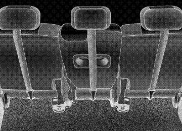
seatbacks to fold with spring assistance. In this position, the back is horizontal and aligned to the rear floor. Second row leather seats have seatback recliners at the 40% seating positions. Raising the lever allows the seat- back to be reclined an additional 11degrees.
then the system will turn off. Thus, a maximum of four hours of operation until the system is reactivated. If the low heat setting is initially selected, the system will operate for two hours and then turn off. If the indicator lamp on the heated seat switch does not light when the switch is depressed or if heated seats does not operate, the system should be serviced by a qualified technician. Second Row 40/20/40 Seat — Fold and Tumble The 40/20/40 seat configuration is standard on all mod- els. This seat is equipped with a unique fold-and-tumble feature. The 40 % seatbacks have spring loaded hinges which assist with the folding of the seatbacks. To fold the 40 % seats, operate the latches by a single lever on the outboard side of each seat. Upon raising the lever slowly, the seatback releases first, allowing the
92 UNDERSTANDING THE FEATURES OF YOUR VEHICLE
Raising the lever allows third row seat passengers to fold the seatbacks and release the latches when exiting the vehicle. Once the seatback is in a folded position continue raising the lever fully to release the cushion latches and tumble the seat. This folding and tumbling action pro- vides easy access to the third row seat.
NOTE: The secondary lever on the rear of each cushion allows third row-seat passengers to release the latches and fold the seatbacks when exiting the vehicle. NOTE: The head restraints must be lowered but do not have to be removed to fold and tumble the seats.
Third Row Seat Bench — If Equipped
To Fold The Seats Folding the third seat occurs in two stages: the cushion is lifted and moved forward then the back is folded. Pull up and forward on either one of the 2 straps at the front of the cushion. The cushion rises on the ends of the U-shaped bracket that pivots on the floor underneath the cushion. If you continue to pull forward, the cushion drops back to the floor directly behind the second seat. Once the cushion has been moved forward, the seatback is free to fold forward flush with the floor.
UNDERSTANDING THE FEATURES OF YOUR VEHICLE 93
94 UNDERSTANDING THE FEATURES OF YOUR VEHICLE
Flat Load Floor Unsnap the flipper panels on the third row seats and flip them forward on the back(s) of the second row seat(s).
To Achieve Maximum Cargo Capacity Pull up the release handles and strap on the second row seats and fold the seat backs flat. Then fold the third row seat flat. Unsnap the flipper panel on the third row seat and flip it forward on the backs of the second row seats. NOTE: When returning the second row seats to their upright position, always snap the third row seat flipper panel(s) back to the third row seat first. NOTE: The head restraints must be lowered when folding the back but do not have to be removed. NOTE: The seat belt buckles are hinged to fold with the back.
UNDERSTANDING THE FEATURES OF YOUR VEHICLE 95
WARNING!
Make sure the cushion is properly engaged under the seatback to properly lock the seatback in the riding position. Do not sit in the 3rd row seat with the second row seatbacks folded or with the second row seats folded and tumbled. In a collision, you could slide under the seat belt and be seriously or even fatally injured.
96 UNDERSTANDING THE FEATURES OF YOUR VEHICLE
Third Seat 50/50 Split Seat — If Equipped
simultaneously into a flat load floor position. The cush- ion and back will move forward together resting on the floor behind the second row seats. The seat belt buckles are hinged to fold with the seatback. To extend the load floor, unsnap the straps and flip the flipper panel(s) on the third row seat forward on the back(s) of the second row seat(s).
To Fold Down The Seat(s) Folding the third row 50/50 seats requires one step. Pull up the release handle and move the seatback forward. This can be done from either in front of or behind the third row seat. The seatback and seat cushion move
To Return The Seat(s) To An Upright Position Snap the flipper panel(s) on the seat back. Then pull on the pull strap on the seat back to reposition the seat(s) to an upright position. NOTE: Make sure the seatback is properly engaged to lock the seatback to a upright position. This can be verified by pulling/pushing forward on the seatback. The seatback will not move forward.
UNDERSTANDING THE FEATURES OF YOUR VEHICLE 97
DRIVER MEMORY SYSTEM — IF EQUIPPED Once programmed, the memory buttons 1 and 2 on the driver’s door panel can be used to recall the driver’s seat position, driver’s outside mirror position, adjustable brake and accelerator pedals position, Automatic Tem- perature Control (ATC) temperature and radio station
98 UNDERSTANDING THE FEATURES OF YOUR VEHICLE
preset settings. Your Remote Keyless Entry transmitters can also be programmed to recall the same positions when the UNLOCK button is pressed.
Your vehicle was delivered with two Remote Keyless Entry transmitters. One or both transmitters can be linked to either memory position. The memory system
can accommodate up to two transmitters, each transmit- ter linked to either of the two memory positions. Setting Memory Positions and Linking Remote Keyless Entry Transmitter to Memory
NOTE: Each time the SET (S) button and a numbered button (1 or 2) are pressed, you erase the memory settings for that button and store new settings. 1. Adjust the driver’s seat, recliner, and both side view mirrors to the desired positions. NOTE: Not all motors may be moved at one time. Please refer to the 8-way power seat description. 2. Adjust the brake and accelerator pedals to the desired positions. 3. Turn on the radio and set the radio station presets (up to 10 AM and 10 FM stations can be set).
the Automatic Temperature Control (ATC)
4. Adjust while the ATC is in Auto mode. 5. Press and release the SET (S) button located on the driver’s door. 6. Within 5 seconds, press and release memory button 1
or 2 on the driver’s door. The next step must be per- formed within 10 seconds if you desire to also use a Remote Keyless Entry transmitter to recall memory po- sitions. 7. Press and release the LOCK button on one of the transmitters. 8. Insert the ignition key and turn the ignition switch to the ON position. 9. Repeat the above steps to set the next memory posi- tion using the other numbered memory button or to link another Remote Keyless Entry transmitter to memory.UNDERSTANDING THE FEATURES OF YOUR VEHICLE 99
memory positions.
Memory Position Recall NOTE: † The driver’s seat belt must be unbuckled to recall † The vehicle must be in Park to recall memory posi- † Not all motors may be moved at one time. Please refer
tions.
to the 8-way power seat description.
To recall the memory settings for driver one, press memory button number 1 on the driver’s door or the Unlock button on the Remote Keyless Entry transmitter linked to memory position 1. To recall the memory setting for driver two, press memory button number 2 on the driver’s door or the Unlock button on the Remote Keyless Entry transmitter linked to memory position 2.
100 UNDERSTANDING THE FEATURES OF YOUR VEHICLE
A recall can be cancelled by pressing any of the memory buttons on the drivers door during a recall (S, 1, or 2), or pressing any one of the power seat buttons, or pressing the adjustable pedals button, or pressing either the LOCK or UNLOCK button on the remote keyless entry trans- mitter when not in the ignition switch. When a recall is cancelled, the driver’s seat, and the pedals stop moving. A delay of one second will occur before another recall can be selected. To Disable A Transmitter Linked to Memory
1. Turn the ignition switch to the OFF position and remove the key. 2. Press and release the memory SET (S) button located on the driver’s door. 3. Within 10 seconds, press and release the UNLOCK button on the Remote Keyless Entry transmitter.
To disable another transmitter linked to either memory position, repeat steps 1-3 for each transmitter. NOTE: The capability to link Remote Keyless Entry transmitters to memory is enabled when delivered from the factory. The capability to link Remote Keyless Entry transmitters to memory can be disabled (or later reen- abled) by a qualified DaimlerChrysler representative. Self-Limiting Control To improve vehicle reliability, the memory system in- cludes a self-limiting control for full travel positioning of power seat and Adjustable Pedal movement (all direc- tions). This self-limiting control may however develop an unintended movement limitation if an obstruction is encountered at sometime during usage. One example of such an occurrence may include a box or package ob- structing the full rearward movement of the driver’s seat. Once the obstruction is removed, the self-limiting control may be restored to maximum position. The self-limiting
control may be restored by first reaching the recently limited or obstructed position, then release and reactivate the same button or buttons. Continued seat travel beyond the obstructed position will indicate the recently encoun- tered self-limitation has been cleared. Driver Easy Exit and Easy Entry Control This additional feature provides automatic driver’s seat positioning which will enhance driver mobility out of and into the vehicle. The seat cushion will move rear- ward approximately 2.5 inches (60 mm) when the key is removed from the ignition switch. The seat will move forward approximately 2.5 inches (60 mm) when the key is placed into the ignition and turned out of the LOCK position, only when the seatbelt is unbuckled. Each stored memory setting will have an associated Easy Exit and Easy Entry position. The Easy Exit and Easy Entry feature may be automatically disabled if the seat is positioned rearward enough and no benefit from moving the seat any farther rearward.
UNDERSTANDING THE FEATURES OF YOUR VEHICLE 101
NOTE: The Easy Exit Easy Entry feature is not enabled when delivered from the factory. The Easy Exit Easy Entry feature may be enabled (or later disabled) by a qualified DaimlerChrysler service representative. Tilt Mirrors in Reverse This additional feature provides automatic outside mir- ror positioning which will aid the driver’s view of the ground rearward of the front doors. The outside mirrors will move slightly downward from the present position when the vehicle is shifted into Reverse position. The outside mirrors will then return to the original position when the vehicle is shifted out of Reverse position. Each stored memory setting will have an associated Tilt Mir- rors in Reverse position. NOTE: The tilt mirrors in Reverse feature is not enabled when delivered from the factory. The Tilt Mirrors in Reverse feature may be enabled (or later disabled) by a qualified DaimlerChrysler service representative.
102 UNDERSTANDING THE FEATURES OF YOUR VEHICLE
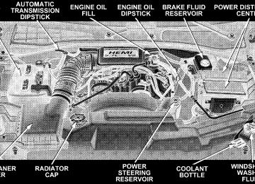
TO OPEN AND CLOSE THE HOOD To open the hood, two latches must be released. First pull the hood release lever located under the left side of the instrument panel.
Then push the safety latch lever to the right. It is located between the grille openings left of the center.
To prevent possible damage, do not slam the hood to close it. Use a firm downward push at the center of the hood to ensure that both latches engage. Never drive your vehicle unless the hood is fully closed, with both latches engaged.
UNDERSTANDING THE FEATURES OF YOUR VEHICLE 103
WARNING!
LIGHTS
If the hood is not fully latched, it could fly up when the vehicle is moving and block your forward vision. Be sure all hood latches are fully latched before driving.
104 UNDERSTANDING THE FEATURES OF YOUR VEHICLE
Interior Lights
Courtesy and dome lights are turned on when the front doors are opened, when the dimmer control (rotating wheel on the right side of the switch) is rotated to the second upward detent position, or when the UNLOCK button is pressed on the key fob. When a door is open and the interior lights are on, rotating the dimmer control
all the way down to the OFF detent will cause all the interior lights to go out. This allows the doors to stay open for extended periods of time without discharging the vehicle’s battery. The brightness of the instrument panel lighting can be regulated by rotating the dimmer control up (brighter) or down (dimmer). When the headlights are ON you can supplement the brightness of the odometer, trip odom- eter, radio and overhead console by rotating the control up until you hear a click. This feature is termed the 9Parade9 mode and is useful when headlights are re- quired during the day. Battery Saver To protect the life of your vehicle’s battery, Load Shed- ding is provided for both the interior and exterior lights.
UNDERSTANDING THE FEATURES OF YOUR VEHICLE 105
If the ignition is off and any door is left ajar for eight minutes or the dimmer control is rotated upwards for eight minutes, the interior lights will automatically turn off. If the headlights remain on while the ignition is cycled off, the exterior lights will automatically turn off after 8
minutes. If the headlights are turned on and left on for 8
minutes while the ignition is off, the exterior lights will automatically turn off. NOTE: Battery Saver mode is cancelled if the ignition is ON. NOTE: While the engine is running, the system will deactivate the Fog Lights and Heated seats if a low battery system voltage is detected.106 UNDERSTANDING THE FEATURES OF YOUR VEHICLE
Headlight Delay To aid in your exit, your vehicle is equipped with a headlight delay that will leave the headlights on for 90
seconds. This delay is initiated when the ignition is cycled off while the headlight switch is on, and then the headlight switch is cycled off. The headlights will remain on for 90 seconds. Headlight delay can be cancelled by either turning the headlight switch ON then OFF or by turning the ignition ON. NOTE: This feature can be disabled by your authorized dealer. Automatic Headlights — If Equipped Automatic Headlights can be activated by rotating the rotary headlight switch to the symbol “A.” The head- lights will turn on when the ignition is in the ON or START position and the ambient light sensor indicates that the headlights should be activated. The headlights will turn off if the headlight switch is rotated to the off position or 90 seconds after the ignition is turned to OFF.Headlights, Parking Lights, Panel Lights
When the headlight switch is rotated to the first position to the right, the parking lights, taillights, side marker lights, license plate light and instrument panel lights are all turned on. The headlights will turn ON when the switch is rotated to the second position. Your vehicle is equipped with plastic headlight lenses that are lighter and less susceptible to stone breakage than glass headlights. Plastic is not as scratch resistant as glass and therefore different lens cleaning procedures must be followed. To minimize the possibility of scratching the lenses and reducing light output, avoid wiping with a dry cloth. To remove road dirt, wash with a mild soap solution fol- lowed by rinsing. Do not use abrasive cleaning components, solvents, steel wool or other abrasive materials to clean the lenses.
UNDERSTANDING THE FEATURES OF YOUR VEHICLE 107
Lights-on Reminder If the headlights, parking lights, or courtesy lights are left On, after the ignition is turned Off, a chime will sound when the driver’s door is opened. Fog Lights — If Equipped
Illuminated Entry Headlights turn on for 90 seconds, when the Remote Keyless Entry UNLOCK button is pressed. NOTE: This feature can be activated by your authorized dealer. Daytime Running Lights (Canada Only) The headlights on your Durango will illuminate when the engine is started. This provides a constant “Lights ON” condition until the ignition is turned OFF. The lights illuminate at reduced intensity. If the parking brake is applied the Daytime Running Lights will turn off. If the headlights are activated, the Daytime Running Lights feature will transition to the normal headlight operating mode.
The foglights are turned ON by placing the headlight rotary control in the parking light, headlight, or Auto
Turn Signals
108 UNDERSTANDING THE FEATURES OF YOUR VEHICLE
position and pressing the fog light button. The fog lights will operate only when the parking lights are ON or when the vehicle headlights are ON low beam. An indicator light located in the instrument cluster will illuminate when the fog lights are on. The fog lights will turn off when the switch is pressed in, when the head- light switch is rotated to the OFF position, or the high beam is selected.
MULTIFUNCTION CONTROL LEVER The multifunction control lever is located on the left side of the steering column.
Move the lever up or down to signal a right-hand or left-hand turn. The arrow on either side of the instrument cluster flashes to indicate the direction of the turn, and proper operation
UNDERSTANDING THE FEATURES OF YOUR VEHICLE 109
High Beam / Low Beam Select Switch Pull the multifunction control lever fully toward the steering wheel to switch the headlights from HIGH or LOW beam.
of the front and rear turn signal lights. If an indicator fails to light when the lever is moved, it would suggest that the switch or indicator lamp is defective. If a defective bulb or wiring circuit is detected for the turn signal system, the arrow indicators will flash at a faster rate. You can signal a lane change by moving the lever partially up or down. NOTE: duration, a continuous chime will sound. Passing Light You can signal another vehicle with your headlights by partially pulling the multifunction lever toward the steer- ing wheel. This will cause the high beam headlights to turn on until the lever is released.
If a turn signal has been left on for at least a mile
110 UNDERSTANDING THE FEATURES OF YOUR VEHICLE
Windshield Wipers
The wipers and washers are operated by a switch in the multifunction control lever. Turn the end of the handle to select the desired wiper speed.
Intermittent Wiper System The intermittent feature of this system was designed for use when weather conditions make a single wiping cycle, with a variable pause between cycles, desirable. For maximum delay between cycles, rotate the control knob into the upper end of the delay range. The delay interval decreases as you rotate the knob until it enters the LO continual speed position. The delay can be regulated from a maximum of about 15 seconds between cycles, to a cycle every 2 seconds. The delay intervals will double in duration when the vehicle speed is 10 mph (16 km) or less.
WARNING!
Sudden loss of visibility through the windshield could lead to an accident. You might not see other vehicles or other obstacles. To avoid sudden icing of the windshield during freezing weather, warm the windshield with defroster before and during wind- shield washer use.
If the front wiper is operating when the ignition NOTE: is turned off, the wiper will automatically return to the 9Park9 position. When the vehicle is restarted, the wipers will resume operation.
UNDERSTANDING THE FEATURES OF YOUR VEHICLE 111
Windshield Washers To use the washer, push in on the washer knob on the end of the multifunction control lever and hold while spray is desired. If the washer knob is depressed while in the delay range, the wiper will operate for several seconds after the washer knob is released. It will then resume the intermittent interval previously selected. If the washer knob is pushed, for a period greater than 1 second, while in the OFF position, the wiper will wipe approximately three wipes, after the wash knob is released. To prevent freeze-up of your windshield washer system in cold weather, select a solution or mixture that meets or exceeds the temperature range of your climate. This rating information can be found on most washer fluid containers.
112 UNDERSTANDING THE FEATURES OF YOUR VEHICLE
TRACTION CONTROL SWITCH — IF EQUIPPED Traction control monitors the amount of wheel spin in each of the driven wheels. If wheel spin is detected, the pressure to the brake system of the slipping wheel(s) is modulated to provide enhanced acceleration. The system operates at speeds typically encountered in city traffic driving. 4WD drive models also include unique logic in 4HI or 4LO to enhance off-road capabilities.
The traction control Indicator, located in the instrument cluster, will light up when the Traction Control is in use. To turn the system OFF, press the Traction Control switch, located below the climate controls in the center stack, until the traction control Indicator in the instru- ment cluster lights up.
UNDERSTANDING THE FEATURES OF YOUR VEHICLE 113
To turn the system back ON, press the switch a second time until the traction control Indicator turns OFF. NOTE: † The traction control Indicator comes on each time the ignition switch is turned ON. This will occur even if you used the switch to turn the system OFF. † The Traction Control system will make buzzing or
clicking sounds when in operation.
TILT STEERING COLUMN To tilt the column, push down on the lever below the turn signal control and move the wheel up or down, as desired.
114 UNDERSTANDING THE FEATURES OF YOUR VEHICLE
WARNING!
DRIVER ADJUSTABLE PEDALS — IF EQUIPPED
Tilting the steering column while the vehicle is moving is dangerous. Without a stable steering col- umn, you could lose control of the vehicle and have an accident. Adjust the column only while the ve- hicle is stopped. Be sure it is locked before driving.
The power adjustable accelerator and brake pedals allow the driver to establish a comfortable position relative to the steering wheel and pedals.
Adjustment
1. Position the driver seat so that you are at least 10
inches (254 mm) away from the airbag located in the center of the steering wheel. 2. Fasten and adjust the seatbelts. 3. Move the adjustable pedal switch, located to the left of the steering column near the parking brake release, up to move the pedals toward the driver or down to move the pedals away from the driver. 4. The pedals cannot be adjusted when the vehicle is in R (Reverse) or when the Speed Control is SET.UNDERSTANDING THE FEATURES OF YOUR VEHICLE 115
CAUTION!
Do not place any article under the adjustable pedals or impede its ability to move as it may cause damage to the pedal controls. Pedal travel may become limited if movement is stopped by an obstruction in the adjustable pedal’s path.
116 UNDERSTANDING THE FEATURES OF YOUR VEHICLE
ELECTRONIC SPEED CONTROL — IF EQUIPPED When engaged, this device takes over accelerator opera- tion at speeds greater than (refer to the table below for the speed for your specific engine). The controls are mounted on the steering wheel.
To Activate Push the ON/OFF button to the ON position. In the instrument cluster, the word “CRUISE” illuminates when the system is on. To Set At A Desired Speed When the vehicle has reached the desired speed, press and release the SET button. Release the accelerator and the vehicle will operate at the selected speed. To Deactivate A soft tap on the brake pedal, normal braking, or pressing the CANCEL button will deactivate speed control with- out erasing the memory. Pushing the ON/OFF button to the OFF position or turning off the ignition erases the memory.
WARNING!
Leaving the Speed Control ON when not in use is dangerous. You could accidentally set the system to cause it to go faster than you want. You could lose control and have an accident. Always leave the system OFF when you aren’t using it.
To Resume Speed To resume a previously set speed, push and release the RESUME button. Resume can be used at any speed above (refer to the table below for the speed for your specific engine). To Vary The Speed Setting When the speed control is on, speed can be increased by pressing and holding the ACCEL button. When the button is released, a new set speed will be established.
UNDERSTANDING THE FEATURES OF YOUR VEHICLE 117
Tapping the ACCEL button once will result in a speed increase (refer to the table below for the speed for your specific engine). Each time the button is tapped, speed increases so that tapping the button three times will increase speed by three increments. Tapping the COAST button once will result in a speed decrease (refer to the table below for the speed for your specific engine). Each time the button is tapped, speed will decrease. For example, tapping the button 3 times will decrease the speed by 3 times the speed listed in the table below (refer to the table below for the speed for your specific engine). To decrease speed while the speed control is on, press and hold the COAST button. Release the button when the desired speed is reached, and the new speed will be set.
118 UNDERSTANDING THE FEATURES OF YOUR VEHICLE
3.7L 35 mph (56 km/h) 30 mph (50 km/h) 2 mph (3km/h) 1 mph (2 km/h) 30 mph (50 km/h)
Functions Engage Speed Minimun RESUME Speed ACCEL Increase COAST Decrease Dropout Speed To Accelerate For Passing Depress the accelerator as you would normally. When the pedal is released, the vehicle will return to the set speed. NOTE: When driving uphill, at elevations above 2,000
feet (610 meters), or when the vehicle is heavily loaded (especially when towing) the vehicle may slow below the SET speed. If the vehicle speed drops below (refer to the table below for the speed for your specific engine), the speed control will automatically disengage. If this hap- pens, you can push down on the accelerator pedal to maintain the desired speed.5.7L 25 mph (40 km/h) 20 mph (32 km/h) 1 mph (2 km/h) 1 mph (2 km/h) 20 mph (32 km/h)
4.7L 35 mph (56 km/h) 30 mph (50 km/h) 2 mph (3km/h) 1 mph (2 km/h) 30 mph (50 km/h) Vehicles equipped with a Automatic transmission may exhibit several downshifts under the above conditions. To reduce the frequency of the downshifts and to im- prove vehicle performance, it is advisable to lock out overdrive by pressing the “TOW/HAUL” button located at the end of the gear shifter.
WARNING!
Speed Control can be dangerous where the system can’t maintain a constant speed. Your vehicle could go too fast for the conditions, and you could lose control. An accident could be the result. Don’t use Speed Control in heavy traffic or on roads that are winding, icy, snow-covered, or slippery.
OVERHEAD CONSOLE The overhead console has the following features:
UNDERSTANDING THE FEATURES OF YOUR VEHICLE 119
† Courtesy Lights † Garage Door Opener — If Equipped † Compass/Temperature Mini-Trip Computer — If
Equipped
120 UNDERSTANDING THE FEATURES OF YOUR VEHICLE
Courtesy/Reading Lights Near the front of the console are two courtesy/reading lights. Both lights illuminate as courtesy lights when a door is opened, when the dimmer control is rotated to the courtesy light position (fully upward position), or when the UNLOCK button is pressed on the Remote Keyless Entry transmitter, if so equipped. These lights are also operated individually as reading lights by pressing the recessed area of the corresponding lens. NOTE: The courtesy/reading lights will remain on until the switch is pressed a second time, so be sure they have been turned off before leaving the vehicle. If the interior lights are left on after the vehicle is turned OFF, they will extinguish after 8 minutes.
COMPASS/TEMPERATURE MINI-TRIP COMPUTER This feature allows you to choose between a compass/ temperature display and one of four trip conditions being monitored. US/M Button Use this button to change the display from U.S. to metric measurement units.
RESET Button
UNDERSTANDING THE FEATURES OF YOUR VEHICLE 121
Global Reset If the RESET button and STEP button are pressed at the same time and held for 3 seconds the Global Reset feature will reset the distance to empty (using a default fuel economy value), trip odometer, and elapsed time displays.
fuel economy,
Use this button to reset the following displays to zero: Average Fuel Economy Trip Odometer Elapsed time.
122 UNDERSTANDING THE FEATURES OF YOUR VEHICLE
Step Button
Use this button to choose or cycle through the four trip conditions.
Average Fuel Economy (AVG ECO) Shows the average fuel economy since the last reset. This display mode becomes less sensitive to instantaneous changes in fuel consumption as the number of total vehicle miles since the last reset increases. It is suggested that this mode be reset periodically for general operation or when driving conditions change significantly (for example, at the end of a trip or when a trailer is connected or disconnected). Distance To Empty (DTE) Shows the estimated distance that can be travelled with the fuel remaining in the tank. The estimated distance is determined by a weighted average of the instantaneous and average fuel economy, according to the current fuel tank level. When Distance To Empty = 0, the fuel gauge pointer will initially be on the red “E” marker. At this point (fuel gauge pointer on the the red “E” marker) there is reserve
fuel capacity, which corresponds to approximately 8% of tank volume. This reserve capacity was put in place to prevent the likelihood of customers running out of fuel when operating at maximum load conditions in areas where there aren’t many gas stations. NOTE: The Distance To Empty will remain equal to zero, until the vehicle runs out of fuel or is refueled. Trip Odometer (ODO) This display shows the distance traveled since the last reset. Elapsed Time (ET) This display shows the accumulated ignition ON time since the last reset.
UNDERSTANDING THE FEATURES OF YOUR VEHICLE 123
C/T Button
Use this button to select a readout of the outside tem- perature and one of eight compass headings that indicate the direction in which the vehicle is facing.
124 UNDERSTANDING THE FEATURES OF YOUR VEHICLE
Compass/Temperature Display
WARNING!
Even if the display still reads a few degrees above 32°F ( 0°C), the road surface may be icy, particularly in woods or on bridges. Drive carefully under such conditions to prevent an accident and possible per- sonal injury or property damage.
Automatic Compass Calibration This compass is self-calibrating which eliminates the need to manually set the compass. When the vehicle is new, the compass may appear erratic and the CAL symbol will be displayed.
After completing one 360° turn, with the vehicle traveling less than 5 mph (8 km/h), in an area free from large metal or metallic objects, the CAL symbol will turn off and the compass will function normally. Manual Compass Calibration
NOTE: To ensure proper compass calibration, make sure the compass variance is properly set before manu- ally calibrating the compass. If the compass appears erratic and the CAL symbol does not appear, you must manually put the compass into the “Calibration” mode. To Put Into a Calibration Mode Turn on the ignition and set the display to “Compass/ Temperature.” Press and hold the RESET button to change the display between VAR (compass variance) and CAL (compass calibration) modes. When the CAL sym- bol is displayed complete one 360 degree turn in an area
free from large metal objects or power lines. The CAL symbol will turn off and the compass will function normally. Compass Variance is the difference between magnetic north and geographic north. In some areas of the country, the difference between magnetic and geographic north is great enough to cause the compass to give false readings. If this occurs, the compass variance must be set according to the Compass Variance Map.
UNDERSTANDING THE FEATURES OF YOUR VEHICLE 125
126 UNDERSTANDING THE FEATURES OF YOUR VEHICLE
To set the variance: Turn the ignition ON and set the display to “Compass/Temperature.” Press and hold the RESET button approximately five seconds. The last vari- ance zone number will be displayed. Press the STEP button to select the new variance zone and press the RESET button to resume normal operation. Outside Temperature Because the ambient temperature sensor is located un- derhood, engine temperature can influence the displayed temperature, therefore, temperature readings are slowly updated when the vehicle speed is below 20 mph (30
km/h) or during stop and go driving.GARAGE DOOR OPENER — IF EQUIPPED The HomeLinkt Universal Transceiver replaces up to three remote controls (hand held transmitters) that oper- ate devices such as garage door openers, motorized gates, or home lighting. It triggers these devices at the push of a button. The Universal Transceiver operates off your vehicle’s battery and charging system; no batteries are needed.
UNDERSTANDING THE FEATURES OF YOUR VEHICLE 127
WARNING!
A moving garage door can cause injury to people and pets in the path of the door. People or pets could be seriously or fatally injured. Only use this transceiver with a garage door opener that has a “stop and reverse” feature as required by federal safety stan- dards. This includes most garage door opener mod- els manufactured after 1982. Do not use a garage door opener without these safety features it could cause injury or death. Call toll-free 1–800–355–3515
or, on the Internet at www.homelink.com for safety information or assistance.For additional information on HomeLinkt, call 1–800– 355–3515, or on the internet at www.homelink.com.
128 UNDERSTANDING THE FEATURES OF YOUR VEHICLE
Programming HomeLink
NOTE: When programming a garage door opener, it is advised to park outside the garage. It is also recom- mended that a new battery be placed in the hand-held transmitter of the device being programmed to HomeLink for quicker training and accurate transmis- sion of the radio-frequency signal. 1. Press and hold the two outer HomeLink buttons, and release only when the indicator light begins to flash (after 20 seconds). Do not hold the buttons for longer than 30
seconds and do not repeat step one to program a second and/or third hand-held transmitter to the remaining two HomeLink buttons.WARNING!
Vehicle exhaust contains carbon monoxide, a danger- ous gas. Do not run the vehicle’s exhaust while training the transceiver. Exhaust gas can cause seri- ous injury or death.
WARNING!
Your motorized door or gate will open and close while you are training the Universal Transceiver. Do not train the transceiver if people or pets are in the path of the door or gate. A moving door or gate can cause serious injury or death to people and pets or damage to objects.
2. Position the end of your hand-held transmitter 1-3
inches (3-8 cm) away from the HomeLink buttons while keeping the indicator light in view. 3. Simultaneously press and hold both the HomeLink button that you want to train and the hand-held trans- mitter buttons. Do not release the buttons until step 4
has been completed.UNDERSTANDING THE FEATURES OF YOUR VEHICLE 129
NOTE: Some gate operators and garage door openers may require you to replace this Programming Step 3 with procedures noted in the 9Gate Operator/Canadian Pro- gramming9 section. 4. The HomeLink indicator light will flash slowly and then rapidly after HomeLink successfully receives the frequency signal from the hand-held transmitter. Release both buttons after the indicator light changes from the slow to the rapid flash. 5. Press and hold the just trained HomeLink button and observe the indicator light. If the indicator light stays on constantly, programming is complete and your device should activate when the HomeLink button is pressed and released. NOTE: To program the remaining two HomeLink but- tons, begin with 9Programming9 step two. Do not repeat step one.
130 UNDERSTANDING THE FEATURES OF YOUR VEHICLE
If the indicator light blinks rapidly for two seconds and then turns to a constant light, continue with (Program- ming( steps 6-8 to complete the programming of a rolling code equipped device (most commonly a garage door opener). 6. At the garage door opener receiver (motor-head unit) in the garage, locate the 9learn9 or 9smart9 button. This can usually be found where the hanging antenna wire is attached to the motor-head unit. 7. Firmly press and release the 9learn9 or 9smart9 button. (The name and color of the button may vary by manu- facturer.) NOTE: There are 30 seconds in which to initiate step eight. 8. Return to the vehicle and firmly press, hold for two seconds and release the programmed HomeLink button. Repeat the (press/hold/release( sequence a second time,
rolling code
and, depending on the brand of the garage door opener (or other rolling code equipped device), repeat this sequence a third time to complete the programming. HomeLink should now activate your equipped device. NOTE: To program the remaining two HomeLink but- tons, begin with 9Programming9 step two. Do not repeat step one. For questions or comments, please contact HomeLink at www.homelink.com or 1-800-355-3515. Canadian Programming/Gate Programming Canadian radio-frequency laws require transmitter sig- nals to 9time-out9 (or quit) after several seconds of transmission which may not be long enough for HomeLink to pick up the signal during programming. Similar to this Canadian law, some U.S. gate operators are designed to 9time-out9 in the same manner.
If you live in Canada or you are having difficulties programming a gate operator by using the 9Program- ming9 procedures (regardless of where you live), replace (Programming HomeLink( step 3 with the following: If programming a garage door opener or gate NOTE: operator, it is advised to unplug the device during the 9cycling9 process to prevent possible overheating. 3. Continue to press and hold the HomeLink button while you press and release every two seconds (9cycle9) your hand-held transmitter until the frequency signal has successfully been accepted by HomeLink. (The indicator light will flash slowly and then rapidly.) Proceed with 9Programming9 step four to complete. Using HomeLink To operate, simply press and release the programmed HomeLink button. Activation will now occur for the trained device (i.e. garage door opener, gate operator, security system, entry door lock, home/office lighting,
UNDERSTANDING THE FEATURES OF YOUR VEHICLE 131
etc.). For convenience, the hand-held transmitter of the device may also be used at any time. In the event that there are still programming difficulties or questions, contact HomeLink at: www.homelink.com or 1-800-355- 3515. Erasing HomeLink Buttons To erase programming from the three buttons (individual buttons cannot be erased but can be 9reprogrammed9 - note below), follow the step noted: † Press and hold the two outer HomeLink buttons until the indicator light begins to flash-after 20 seconds. Release both buttons. Do not hold for longer that 30
seconds. HomeLink is now in the train (or learning) mode and can be programmed at any time beginning with 9Programming9 - step 2.132 UNDERSTANDING THE FEATURES OF YOUR VEHICLE
Reprogramming a Single HomeLink Button To program a device to HomeLink using a HomeLink button previously trained, follow these steps: 1. Press and hold the desired HomeLink button. Do NOT release the button. 2. The indicator light will begin to flash after 20 seconds. Without releasing the HomeLink button, proceed with 9Programming9 step 2
For questions or comments, contact HomeLink at: www.homelink.com or 1-800-355-3515. SecurityGarage Door Opener Operation with Security Alarm (if equipped) If your vehicle is equipped with the Security Alarm feature, the operation of the HomeLink feature will be purposely inhibited if the Security Alarm is 9Armed9. This prevents HomeLink operation due to un-authorized
vehicle entry. HomeLink operation will be re-stored when the Security Alarm has been 9Disarmed9. If you sell your vehicle, be sure to erase the frequencies. To erase all of the previously trained frequencies, hold down both outside buttons until the green light begins to flash. This device complies with part 15 of FCC rules and with RSS-210 of Industry Canada. Operation is subject to the following conditions: † This device may not cause harmful interference. † This device must accept any interference that may be received including interference that may cause undes- ired operation.
NOTE: Changes or modifications not expressly ap- proved by the party responsible for compliance could void the user’s authority to operate the equipment.
HomeLinkt is a trademark owned by Johnson Controls, Inc.
POWER SUNROOF — IF EQUIPPED The power sunroof control is located between the sun visors on the overhead console. Pressing the 9open9 end of the rocker switch once moves the panel to a comfort stop position short of full opening. Pressing and holding the switch causes the panel to continue moving rearward, up to the full-open position. To close the panel, the 9close9 end of the switch must be pressed and held. Pressing the “vent” button from a fully closed position, raises the trailing edge of the panel for ventilation. When the panel is venting, pressing the “close” end or the rocker switch returns it to the closed position. Both opening and closing operations in the vent mode occur only while the switch is held.
UNDERSTANDING THE FEATURES OF YOUR VEHICLE 133
NOTE: The sunroof will continue to operate for ten minutes after the ignition is turned OFF or until the driver door is opened. This feature may be disabled by your authorized dealer. Express Open Feature During the Express Open operation, any movement of the switch will stop the sunroof and it will remain in a partial open position. Again, momentarily pressing the switch rearward will activate the Express Open Feature. To close the sunroof, hold the switch in the forward position. Again, any release of the switch will stop the movement and the sunroof will remain in a partial open condition until the switch is pushed forward again. To close fully, hold the switch in the forward position until the glass movement has stopped. The sunshade can be opened manually. It will also open as the sunroof opens. The sunshade cannot be closed if the sunroof is open.
134 UNDERSTANDING THE FEATURES OF YOUR VEHICLE
WARNING!
WARNING!
Never leave children in a vehicle, with the keys in the ignition switch. Occupants, particularly unat- tended children, can become entrapped by the power sunroof while operating the power sunroof switch. Such entrapment may result in serious injury or death.
In an accident, there is a greater risk of being thrown from a vehicle with an open sunroof. You could also be seriously injured or killed. Always fasten your seat belt properly and make sure all passengers are properly secured too. Do not allow small children to operate the sunroof. Never allow fingers or other body parts, or any object to project through the sunroof opening. Injury may result.
Wind Buffeting Wind buffeting can be described as the perception of pressure on the ears or a helicopter type sound in the ears. Your vehicle may exhibit wind buffeting with the windows down, or the sunroof (if equipped) in certain open or partially open positions. This is a normal occur- rence and can be minimized. If the buffeting occurs with
the rear windows open, open the front and rear windows together to minimize the buffeting. If the buffeting occurs with the sunroof open, adjust the sunroof opening to minimize the buffeting or open any window. Sunroof Maintenance Use only a nonabrasive cleaner and a soft cloth to clean the glass panel.
ELECTRICAL POWER OUTLETS This vehicle has three auxiliary power outlets that can provide up to 20 Amps of current for accessories de- signed for use with the standard power outlet adapters. The outlet located in the lower portion of the instrument panel has a snap on a plastic cap so that it can be covered when not in use. As a safety precaution, the outlet in the instrument panel only operates with the ignition switch ON. When the optional Cigar Lighter heating element is
UNDERSTANDING THE FEATURES OF YOUR VEHICLE 135
used, it heats when pushed in and pops out automati- cally when ready for use. To preserve the heating element, do not hold the lighter in the heating position. There are two additional 12 V/(20 total Amps for both outlets) power outlets, one located in the storage bin of the center console and another located in the right rear cargo area. These outlets can be reconfigured by the customer to operate only when the ignition is ON (switched battery fed) or with the ignition ON or OFF (battery fed) to allow for cellular telephone charging and or operation while the ignition is off. NOTE: All accessories connected to these outlets should be removed or turned OFF when the vehicle is not in use to protect the battery against discharge (unless the cus- tomer has reconfigured the fuse block to switched battery feed).
136 UNDERSTANDING THE FEATURES OF YOUR VEHICLE
Electrical Outlet Use With Engine OFF (Battery Fed Configuration)
CAUTION!
† Many accessories that can be plugged in draw power from the vehicle’s battery, even when not in use (i.e. cellular phones, etc.). Eventually, if plugged in long enough, the vehicle’s battery will discharge suffi- ciently to degrade battery life and/or prevent engine starting. † Accessories that draw higher power (i.e. coolers, vacuum cleaners, lights, etc.), will discharge the battery even more quickly. Only use these intermit- tently and with greater caution. † After the use of high power draw accessories, or long periods of the vehicle not being started (with accessories still plugged in), the vehicle must be driven a sufficient length of time to allow the generator to recharge the vehicle’s battery.
Reconfiguring Power Outlets To reconfigure the outlets, be sure the ignition is OFF before removing the fuse. The reconfigurable fuse loca- tion is a special design that allows the fuse to be installed in two different ways. If the fuse is located in the 9Upper or Top Position9 the outlets will work at all times. If the fuse is located in the 9Lower or Bottom Position9 the power outlets will only work when the ignition is ON. NOTE: The fuse block is located in the left side kick panel behind a removable cover near the park brake pedal.
UNDERSTANDING THE FEATURES OF YOUR VEHICLE 137
FLOOR CONSOLE
Floor Console Features The Floor Console between the driver’s and front pas- senger’s seat, has the following features: † Miscellaneous storage compartments † Flexible cup holder inserts † Portable phone storage bin † Portable phone cord routing † 12 Volt battery fed power outlet inside storage com- † Side open armrest lid † Tissue holder & pen holder † Coin slots † Removable CD bin
partment
138 UNDERSTANDING THE FEATURES OF YOUR VEHICLE
The coin slots are located under the instrument panel center stack.
Cup Holders The Durango has 8 cupholders. Four are located in the center console, two are located in the second row armrest, and two are located in the right hand quarter panel for
third row occupants. The four cupholders located in the center console may be removed for cleaning and are dishwasher safe. Power Outlet and Portable Phone Storage The console is equipped with a power outlet, portable phone storage bin, and phone cord routing. The phone storage bin can be used when easy access to the phone is needed. Also, the power outlet inside the console com- partment can be used to power up the phone while it is being stored in the bin. To use, plug in the portable power recharge cord and place the cord along the opening under the forward portion of the storage bin. Close the console armrest lid and plug the power cord into the phone while resting the phone in the bin. The power outlet may be used for any portable item with a standard 12 volt power outlet adaptor, requiring up to 20 Amps of current. The power outlet is on all the time.
FACTORY INSTALLED ROOF LUGGAGE RACK— IF EQUIPPED
UNDERSTANDING THE FEATURES OF YOUR VEHICLE 139
The side rails between the stantions should be used to tie down cargo. Check the straps frequently to be sure that the load remains securely attached. NOTE: Crossbars are offered by Mopart accessories. External racks do not increase the total load carrying capacity of the vehicle. Be sure that the total occupant and luggage load inside the vehicle, plus the load on the luggage rack, do not exceed the maximum vehicle load capacity.
The load carried on the roof when equipped with a luggage rack must not exceed 68 kg (150 lbs.), and should be uniformly distributed over the cargo area.
140 UNDERSTANDING THE FEATURES OF YOUR VEHICLE
CAUTION!
WARNING!
Cargo must be securely tied before driving your vehicle. Improperly secured loads can fly off the vehicle, particularly at high speeds, resulting in personal injury or property damage. Follow the roof rack Cautions when carrying cargo on your roof rack.
To avoid damage to the roof rack and vehicle, do not exceed the maximum roof rack load capacity. Always distribute heavy loads as evenly as possible and secure the load appropriately. Long loads which extend over the windshield, such as wood panels or surfboards, should be secured to both the front and rear of the vehicle. Place a blanket or other protection between the surface of the roof and the load. Travel at reduced speeds and turn corners carefully when carrying large or heavy loads on the roof rack. Wind forces, due to natural causes or nearby truck traffic, can add sudden upward loads. This is espe- cially true on large flat loads and may result in damage to the cargo or your vehicle.
INSTRUMENT PANEL AND CONTROLS
CONTENTS
m Instruments And Controls . . . . . . . . . . . . . . . . . 144
m Instrument Cluster . . . . . . . . . . . . . . . . . . . . . . 145
m Instrument Cluster Description . . . . . . . . . . . . . 146
m Radio Reception Information . . . . . . . . . . . . . . . 154
N AM Reception . . . . . . . . . . . . . . . . . . . . . . . 154
N FM Reception . . . . . . . . . . . . . . . . . . . . . . . . 154
m Electronic Digital Clock . . . . . . . . . . . . . . . . . . 154
N Clock Setting Procedure . . . . . . . . . . . . . . . . . 155m Sales Code REF — AM/FM/CD (Single Disc) Radio With Optional Hands Free Phone Capability . . . . 155
N Operating Instructions - Radio Mode . . . . . . . 156
N Operation Instructions - CD Mode . . . . . . . . . 159
N Operating Instructions - Hands Free Phone —If Equipped . . . . . . . . . . . . . . . . . . . . . . . . . 161
m Sales Code RAQ – AM/FM/CD (6-Disc) Radio
With Optional Satellite Radio, Hands Free Phone, And Video Capabilities . . . . . . . . . . . . . . . . . . . 161
N Operating Instructions - Radio Mode . . . . . . . 161142 INSTRUMENT PANEL AND CONTROLS
N Operation Instructions -
(CD Mode For CD Audio Play)
. . . . . . . . . . . 165
N Load/Eject Button
(CD Mode For CD Audio Play)
N Notes On Playing MP3 Files N Operation Instructions -
. . . . . . . . . . . 166
. . . . . . . . . . . . . 168(CD Mode For MP3 Audio Play)
. . . . . . . . . . 171
N Load/Eject Button (CD Mode For MP3 Play) . . 171
m Satellite Radio — If Equipped . . . . . . . . . . . . . . 173
N System Activation . . . . . . . . . . . . . . . . . . . . . 173
N Electronic Serial Number/Sirius IdentificationNumber (ENS/SID) . . . . . . . . . . . . . . . . . . . . 173
N Selecting Satellite Mode In REF Radios . . . . . . 174
N Selecting Satellite Mode In RAQ Radios . . . . . 174N Selecting a Channel . . . . . . . . . . . . . . . . . . . . 175
N Storing And Selecting Pre-Set Channels . . . . . . 175
N Using The PTY (Program Type) Button(If Equipped)
. . . . . . . . . . . . . . . . . . . . . . . . 175
N PTY Button 9Scan9 . . . . . . . . . . . . . . . . . . . . . 175
N PTY Button 9Seek9 . . . . . . . . . . . . . . . . . . . . . 176
N Satellite Antenna . . . . . . . . . . . . . . . . . . . . . . 176
N Reception Quality . . . . . . . . . . . . . . . . . . . . . 176
m Remote Sound System Controls — If Equipped . . 177
N Radio Operation . . . . . . . . . . . . . . . . . . . . . . 177
N CD Player . . . . . . . . . . . . . . . . . . . . . . . . . . 178
m Compact Disc Maintenance . . . . . . . . . . . . . . . . 178
m Radio Operation And Cellular Phones . . . . . . . . 179m Climate Controls . . . . . . . . . . . . . . . . . . . . . . . 179
N Manual Control . . . . . . . . . . . . . . . . . . . . . . 179
N Air Conditioning Operation . . . . . . . . . . . . . . 180
N Front Blower Control . . . . . . . . . . . . . . . . . . . 180
N Front Mode Control . . . . . . . . . . . . . . . . . . . 181
N Rear Temperature Control — If Equipped . . . . 183
N Rear Window Defrosting And Rear WindowWasher/Wiper
. . . . . . . . . . . . . . . . . . . . . . . 184
N Automatic Temperature Control (ATC) —
If Equipped . . . . . . . . . . . . . . . . . . . . . . . . . 184
. . . . . . . . . . . . . . . . . . . . 184N Automatic Control
INSTRUMENT PANEL AND CONTROLS 143
N Level Of Automatic Control . . . . . . . . . . . . . . 185
N Manual Control (ATC) . . . . . . . . . . . . . . . . . . 186
N Rear Zone Climate Control — If Equipped . . . 189
N Rear Rotary Temperature Control . . . . . . . . . . 190
N Front Unit To Rear Unit Chart . . . . . . . . . . . . 191
N Operating Tips . . . . . . . . . . . . . . . . . . . . . . . 191
N Operating Tips Chart . . . . . . . . . . . . . . . . . . . 193
m Rear Window Features . . . . . . . . . . . . . . . . . . . 194
N Rear Window Wiper/Washer . . . . . . . . . . . . . 194
N Rear Window Defrosting . . . . . . . . . . . . . . . . 195144 INSTRUMENT PANEL AND CONTROLS
INSTRUMENTS AND CONTROLS
Instrument Cluster
INSTRUMENT PANEL AND CONTROLS 145
146 INSTRUMENT PANEL AND CONTROLS
INSTRUMENT CLUSTER DESCRIPTION
1. Fuel Gage
The fuel gauge shows level of fuel in tank when ignition switch is in the ON position.
2. Temperature Gage
The temperature gage indicates engine coolant temperature. Any reading within the normal range indicates that the cooling system is operat- ing satisfactorily. The gage needle in V6 and V8 engines will likely indicate a high temperature when driving in hot weather, up mountain grades, in heavy traffic, or when towing a trailer. If the needle rises to the “H” mark, stop the vehicle, shift into N (Neutral) increase engine speed for 2-3 minutes. If the temperature reading does not return to normal, seek authorized service immedi- ately.
CAUTION!
Do not leave your vehicle unattended with the engine running as you would not be able to react to the temperature indicator if the engine overheats.
The gage pointer will remain near its last reading when the engine is turned off. It will return to a true reading when the engine is restarted. 3. Turn Signal Indicators is activated, a right-pointing or When a turn signal left-pointing arrow lights up and flashes to indicate the direction of the turn. These indicators also indicate proper operation of the front and rear turn signal lights. If either indicator flashes at a faster rate than normal, check for a defective bulb. If either indicator fails to light up when the lever is moved, check for a defective fuse or turn signal LED. A single chime is activated when the
INSTRUMENT PANEL AND CONTROLS 147
7. Fog Light Indicator — If Equipped
This light shows when the fog lights are ON.
8. Coolant Temperature Light
This light warns of an overheated engine condi- tion. For a bulb check, this light will come on momentarily when the ignition is turned On. If the light turns on while driving, stop the vehicle, shift into N (Neutral) and increase the engine speed for 2 to 3
minutes. If the temperature reading does not return to normal, seek authorized service immediately.left/right turn signal is left on with the engine RPM vehicle speed greater than 15 mph (24 km/h) for more than one mile. 4. Low Fuel Warning Light
This indicator lights when the fuel gauge reads 1/8
of a tank or less.5. High Beam Indicator
Indicates that headlights are on high beam.
6. Seat Belt Reminder Light
This light comes on for several seconds after the ignition is turned ON as a reminder to “buckle up.” This light will remain on as long as the seat belt remains unbuckled. If this light flashes, it indicates a fault in the airbag system. Have the system checked by an authorized dealer.
148 INSTRUMENT PANEL AND CONTROLS
CAUTION!
WARNING!
Driving with a hot engine cooling system could damage your vehicle. If the temperature light is on, safely pull over and stop the vehicle. Idle the vehicle in neutral with the air conditioner turned off until the light turns off. If the if the light remains on, turn the engine off immediately, and call for service.
A hot engine cooling system is dangerous. You or others could be badly burned by steam or boiling coolant. You may want to call a service center if your vehicle overheats. If you decide to look under the hood yourself, see Section 7 of this manual. Follow the warnings under the Cooling System Pressure Cap paragraph.
9. Speedometer Shows vehicle speed in miles per hour and kilometers per hour. 10. Voltage Light
This light monitors the electrical system voltage. The light should turn on momentarily as the
engine is started. If the light stays on or turns on while driving, it indicates a problem with the charging system. Immediate service should be obtained. 11. Liftgate Open The Gate Open light will illuminate when the liftgate is not properly closed and the ignition is ON. 12. Security Light This light will flash rapidly for approximately 15 seconds when the vehicle theft alarm is arming. The light will flash at a slower speed continuously after the alarm is set. The security light will also come on for about three seconds when the ignition is first turned on. 13. ABS Warning Light
This light monitors the Anti-Lock Brake System which is described elsewhere in this manual. This light will come on when the ignition key is turned to the ON position and may stay on for approximately 3 seconds. If this light remains on or
INSTRUMENT PANEL AND CONTROLS 149
comes on during driving, it indicates that the Anti-Lock portion of the brake system is not functioning and that service is required. See your authorized dealer immedi- ately. 14. Engine Oil Pressure Indicator Light
This light indicates that the engine oil pressure has become too low. For a bulb check, this light will come on momentarily when the ignition is turned On. If the light turns on while driving, stop the vehicle and shut off the engine as soon as possible. Immediate service should be obtained. 15. Tachometer This gage measures engine revolutions-per-minute (rpm x 1000). 16. Gear Selector The electronic gear selector display is self-contained within the instrument cluster. It displays the position of the automatic transmission shift lever, and the relation of
150 INSTRUMENT PANEL AND CONTROLS
each position to all other positions. For a good signal the display will place a box around the selected transmission range (PRND21). If the PRNDL displays only the char- acters PRND21 (no boxes) have the system checked by an authorized dealer. 17. Transfer Case Position and Service (SVC) Indicators These lights monitor the electric shift 4WD system for transfer case position and function. If there are no indi- cator lights ON or flashing the transfer case is in All- Wheel-Drive (AWD) position. The SVC 4WD lights will come on when the ignition key is turned to the ON position and will stay on for 2 seconds. If the light stays on or comes on during driving, it means that the 4WD system is not functioning properly and that service is required.
18. Traction Control — If Equipped
This display indicator illuminates momentarily as a bulb check when the ignition switch is first turned ON. The indicator will blink during an active traction event, but will remain solid when the system is deactivated or if a system malfunc- tion occurs. The Traction Control indicator will turn ON if: † The Traction Control system is in use. † The Traction Control switch has been used to turn † There is an Anti-Lock Brake system malfunction or † The system has been deactivated to prevent damage to the brake system due to overheated brake tem- peratures.
Traction Control system malfunction.
the system OFF.
NOTE: Extended heavy use of Traction Control may cause the system to deactivate and turn on the Traction Control indicator. This is to prevent overheating of the brake system and is a normal condition. The system will remain disabled for about 4 minutes until the brakes have cooled. The system will automatically reactivate and turn off the Traction Control indicator. 19. Transmission Temperature Indicator This light indicates that there is excessive transmission fluid temperature that might occur with severe usage such as trailer towing. If this light comes on, stop the vehicle and run the engine at idle or faster, with the transmission in NEUTRAL until the light goes off. 20. Electronic Throttle Control (ETC) Light 5.7L Engines Only
This light informs you of a problem with the Electronic Throttle Control system. If a prob- lem is detected the light will come on while the
INSTRUMENT PANEL AND CONTROLS 151
engine is running. If the light remains lit with the engine running your vehicle will usually be drivable, however, see your dealer for service as soon as possible. If the light is flashing when the engine is running, immediate service is required and you may experience reduced perfor- mance, an elevated/rough idle or engine stall and your vehicle may require towing. The light will come on when the ignition is first turned on and remain on briefly as a bulb check. If the light does not come on during starting, have the system checked by an authorized dealer. 21. Door Ajar The Door Ajar light will illuminate when the ignition is ON and any one of the passenger doors are opened. NOTE: A chime will sound if the vehicle is rolling and a door has been opened. 22. BRAKE System Warning Light This light will light when the ignition key is turned to the ON position and will remain on for a few seconds. If the
152 INSTRUMENT PANEL AND CONTROLS
light stays on, it may be an indication that the parking brake has not been released, or there is a low brake fluid level. If the light remains on when the parking brake has been disengaged, and the fluid level is at the full mark on the master cylinder reservoir, it indicates a possible brake hydraulic system malfunction. In this case, the light will remain on until the condition has been corrected. If the parking brake is applied, the light will flash when the gear position is out of park for automatic transmissions. If brake failure is indicated, immediate repair is neces- sary. Operating the vehicle in this condition is danger- ous!
23. TOW/HAUL The TOW/HAUL button is located at the end of the gear shift lever. This light will illuminate when the TOW/ HAUL button has been selected.
24. Malfunction Indicator Light
This light is part of an onboard diagnostic system which monitors the emissions and engine control system. If the vehicle is ready for emissions testing the light will come on when the ignition is first turned on and remain on, as a bulb check, until the engine is started. If the vehicle is not ready for emissions testing the light will come on when the ignition is first turned on and remain on for 15 seconds, then blink for 5
seconds, and remain on until the vehicle is started. If the bulb does not come on during starting, have the condi- tion investigated promptly. If this light comes on and remains on while driving, it suggests a potential engine control problem and the need for system service. Although your vehicle will usually be drivable and not need towing, see your dealer for service as soon as possible.CAUTION!
Prolonged driving with the MIL on could cause damage to the engine control system. It also could affect fuel economy and driveability. If the MIL is flashing, severe catalytic converter damage and power loss will soon occur. Immediate service is required.
25. Airbag Indicator
The indicator lights and remains lit for 6 to 8
seconds when the ignition is first turned ON. If the light does not come on when the ignition is first turned on, or the light stays on or comes on while driving, have the airbag system checked by an authorized dealer.INSTRUMENT PANEL AND CONTROLS 153
26. Low Washer Fluid Indicator This light comes on when the washer fluid level falls below approximately 1/4 full. The light will remain on until fluid is added and ignition switch is cycled. 27. Cruise Light This indicator lights when the electronic speed control system is turned on. 28. Odometer/Trip Odometer The odometer shows the total distance the vehicle has been driven. U.S. federal regulations require that upon transfer of vehicle ownership, the seller certify to the purchaser the correct mileage that the vehicle has been driven. There- fore, if the odometer reading is changed during repair or replacement, be sure to keep a record of the reading before and after the service so that the correct mileage can be determined.
154 INSTRUMENT PANEL AND CONTROLS
The trip odometer shows individual trip mileage. To toggle between the odometer and the trip odometer, press the Odometer/Trip Odometer Button. 29. Odometer/Trip Odometer Button Press this button to toggle between the odometer and the trip odometer display. Holding the button in resets the trip odometer reading.
RADIO RECEPTION INFORMATION
AM Reception AM radio signals usually travel longer distances than FM signals, especially at night. These longer distance AM signals can cause AM stations to interfere with one another. Noise from storms and power lines can also interfere with AM reception. Reducing the treble can reduce some of the noise.
FM Reception FM Stereo signals produce better sound quality than AM signals. However, FM signals will only travel approxi- mately 10 to 40 miles (16 to 64 km). Tall structures or hills can cause interference with FM signals causing the sound to cut out.
ELECTRONIC DIGITAL CLOCK The clock and radio each use the display panel built into the radio. A digital readout shows the frequency and/or time in hours and minutes (depending on your radio model) whenever the ignition switch is in the “ON” or “ACC” position. When the ignition switch is in the “OFF” position, or when the radio frequency is being displayed, time keep- ing is accurately maintained. On the RAQ radio the time button alternates the location of the time and frequency on the display. On the REF only one of the two, time or frequency is displayed at a time.
Clock Setting Procedure
1. Press and hold the time button until the hours blink. 2. Adjust the hours by turning the right side Tune / Audio control. 3. After the hours are adjusted, press the right side Tune / Audio control to set the minutes. 4. Adjust the minutes using the right side Tune / Audio control. 5. To exit, press any button/knob or wait approximately 5 seconds.
INSTRUMENT PANEL AND CONTROLS 155
SALES CODE REF — AM/FM/CD (SINGLE DISC) RADIO WITH OPTIONAL HANDS FREE PHONE CAPABILITY
156 INSTRUMENT PANEL AND CONTROLS
Operating Instructions - Radio Mode
NOTE: The ignition switch must be in the ON or ACC position to operate the radio. Power Switch/Volume Control (Rotary) Press the ON/VOL control to turn the radio ON. Press the ON/VOL a second time to turn OFF the radio. Electronic Volume Control The electronic volume control turns continuously (360
degrees) in either direction without stopping. Turning the volume control to the right increases the volume and to the left decreases it. When the audio system is turned on, the sound will be set at the same volume level as last played. For your convenience, the volume can be turned down, but not up, when the audio system is off and the ignition is ON.Mode Button (Radio Mode) Press the mode button repeatedly to select between the CD player or Satellite Radio (if equipped). SEEK Button (Radio Mode) Press and release the SEEK button to search for the next listenable station in either AM/FM or Satellite (if equipped) mode. Press the right side of the button to seek up and the left side to seek down.The radio will re- mained tuned to the new station until you make another selection. Holding the button will bypass stations with- out stopping until you release it. MUTE Button (Radio Mode) Press the MUTE button to cancel the sound from the speakers. 9MUTE9 will be displayed. Press the MUTE button a second time and the sound from the speakers will return. Rotating the volume control, turning the radio ON /OFF, or turning ON/OFF the ignition, will cancel the MUTE feature.
In Hands Free Phone (if equipped) mode, the
NOTE: MUTE button mutes the microphone. SCAN Button (Radio Mode) Pressing the SCAN button causes the tuner to search for the next listenable station, in either AM, FM or Satellite (if equipped) frequencies, pausing for 5 seconds at each listenable station before continuing to the next. To stop the search, press SCAN a second time. PSCAN Button (Radio Mode) Pressing the PSCAN button, causes the tuner to scan through preset stations, in either AM, FM or Satellite (if equipped) frequencies, pausing for 5 seconds at each preset station before continuing to the next. To stop the search, press PSCAN a second time.
INSTRUMENT PANEL AND CONTROLS 157
RW/FF (Radio Mode) Pressing the rewind/fast forward button causes the tuner to search for the next frequency in the direction of the arrows. This feature operates in either AM, FM or Satel- lite (if equipped) frequencies. TUNE Control (Radio Mode) Turn the right side rotary control to increase or decrease the frequency. AM/FM Button (Radio Mode) Press the button to select AM or FM Modes. Setting the Tone, Balance, and Fade Press the rotary TUNE control and BASS will display. Turn the TUNE control to the right or left to increase or decrease the Bass tones. Press the rotary TUNE control a second time and MID will display. Turn the TUNE control to the right or left to increase or decrease the Mid Range tones.
158 INSTRUMENT PANEL AND CONTROLS
Press the rotary TUNE control a third time and TREBLE will display. Turn the TUNE control to the right or left to increase or decrease the Treble tones. Press the rotary TUNE control a fourth time and BAL will display. Turn the TUNE control to the right or left to adjust the sound level from the right or left side speakers. Press the rotary TUNE control a fifth time and FADE will display. Turn the TUNE control to the right or left to adjust the sound level between the front and rear speak- ers. Press the tune control again or wait 5 seconds and the radio will return to normal display. SET Button (Radio Mode) To SET The Push-Button Memory When you are receiving a station that you wish to commit to push-button memory, press the SET button. The symbol SET 1 will now show in the display window.
Select the button (1-6) you wish to lock onto this station and press and release that button. If a button is not selected within 5 seconds after pressing the SET button, the station will continue to play but will not be stored into push-button memory. You may add a second station to each push-button by repeating the above procedure with this exception: Press the SET button twice and SET 2 will show in the display window. Each button can be set for SET 1 and SET 2 in both AM and FM. This allows a total of 12 AM,12 FM and 12 Satellite (if equipped) stations to be stored into push- button memory. The stations stored in SET 2 memory can be selected by pressing the push-button twice. Every time a preset button is used a corresponding button number will be displayed.
Preset Buttons 1 - 6 (Radio Mode) These buttons tune the Radio to the stations that you commit to push-button memory {12 AM, 12 FM, and 12
Satellite (if equipped) stations}. Operation Instructions - CD ModeNOTE: The ignition switch must be in the ON or ACC position to operate the radio. Inserting The Compact Disc (Single CD Player) Gently insert one CD into the CD player with the CD label facing up. The CD will automatically be pulled into the CD Player and the CD icon will illuminate on the radio display. If the volume control is ON, the unit will switch to CD mode and begin to play. The display will show the track number and play time in minutes and seconds. Play will begin at the start of track one.
INSTRUMENT PANEL AND CONTROLS 159
switch OFF.
NOTE: † You may insert or eject a disc with the radio or ignition † If you insert a disc with the ignition ON and the radio OFF, the CD will automatically be pulled into the CD Player and the display will show the time of day.
SEEK Button (CD Mode) Press the right side of the SEEK button for the next track on the CD. Press the left side of the button to return to the beginning of the current track, or return to the beginning of the previous track if the CD is within the first 10
seconds of the current selection. MUTE Button ((CD Mode) Press the MUTE button to cancel the sound from the speakers. 9MUTE9 will be displayed. Press the MUTE button a second time and the sound from the speakers will return. Rotating the volume control or turning OFF the ignition will also return the sound from the speakers.160 INSTRUMENT PANEL AND CONTROLS
SCAN Button (CD Mode) Press this button to play the first 10 seconds of each track. To stop the scan function, press the button a second time. EJECT Button (CD Mode)
Press this button and the disc will unload and move to the entrance for easy removal. The unit will switch to the last selected mode.
If you do not remove the disc within 15 seconds, it will be reloaded. The radio mode will continue to appear. TIME Button (CD Mode) Press this button to change the display from elapsed CD playing time to time of day. RW/FF (CD Mode) Press and hold the FF (Fast Forward) and the CD player will begin to fast forward until FF is released. The RW (Reverse) button works in a similar manner.
NOTE: RND Button (Random Play Button) (CD Mode) Press this button while the CD is playing to activate Random Play. This feature plays the selections on the compact disc in random order to provide an interesting change of pace. Press the SEEK button to move to the next randomly selected track. Press and hold the FF button to fast forward through the tracks. Release the FF button to stop the fast forward feature. If the RW button is pressed, the current track will reverse to the beginning of the track and begin playing. Press the RDN button a second time to stop Random Play.
Operating Instructions - Hands Free Phone — If Equipped Refer to the HANDS FREE PHONE (UConnect™) section of the Owner’s Manual.
SALES CODE RAQ – AM/FM/CD (6-DISC) RADIO WITH OPTIONAL SATELLITE RADIO, HANDS FREE PHONE, AND VIDEO CAPABILITIES
INSTRUMENT PANEL AND CONTROLS 161
Operating Instructions - Radio Mode
NOTE: The ignition switch must be in the ON or ACC position to operate the radio. Power Switch/Volume Control (Rotary) Press the ON/VOL control to turn the radio ON. Press the ON/VOL a second time to turn OFF the radio. Electronic Volume Control The electronic volume control turns continuously (360
degrees) in either direction without stopping. Turning the volume control to the right increases the volume and to the left decreases it. When the audio system is turned on, the sound will be set at the same volume level as last played. For your convenience, the volume can be turned down, but not up, when the audio system is off and the ignition is ON.162 INSTRUMENT PANEL AND CONTROLS
Mode Button (Radio Mode) Press the mode button repeatedly to select between the Radio, CD player, Hands Free Phone, Satellite, or Vehicle Entertainment System (VES) (if equipped). SEEK Button (Radio Mode) Press and release the SEEK button to search for the next station in either AM/FM or Satellite (if equipped) mode. Press the right side of the button to seek up and the left