- 2013 Chrysler TOWN and Country Owners Manuals
- Chrysler TOWN and Country Owners Manuals
- 2006 Chrysler TOWN and Country Owners Manuals
- Chrysler TOWN and Country Owners Manuals
- 2011 Chrysler TOWN and Country Owners Manuals
- Chrysler TOWN and Country Owners Manuals
- 2007 Chrysler TOWN and Country Owners Manuals
- Chrysler TOWN and Country Owners Manuals
- 2010 Chrysler TOWN and Country Owners Manuals
- Chrysler TOWN and Country Owners Manuals
- 2005 Chrysler TOWN and Country Owners Manuals
- Chrysler TOWN and Country Owners Manuals
- 2009 Chrysler TOWN and Country Owners Manuals
- Chrysler TOWN and Country Owners Manuals
- 2004 Chrysler TOWN and Country Owners Manuals
- Chrysler TOWN and Country Owners Manuals
- 2012 Chrysler TOWN and Country Owners Manuals
- Chrysler TOWN and Country Owners Manuals
- 2008 Chrysler TOWN and Country Owners Manuals
- Chrysler TOWN and Country Owners Manuals
- Download PDF Manual
-
286 STARTING AND OPERATING
TRAVEL CONDI- TION
MAXIMUM TRAILER WEIGHT (TRAILER FRONTAL AREA NOT TO EXCEED 32
SQ. FT.) 3.3L,& 3.8L EN- GINES WITH 4-SPEED AUTO- MATIC TRANS- AXLE MAX. COMBINED WEIGHT OF VE- HICLE AND TRAILER NOT TO EXCEED 6,600 lbs (2993 kg)3.3L & 3.8L EN- GINES WITH HEAVY DUTY TRAILER TOW PACKAGE MAX. COMBINED WEIGHT OF VE- HICLE AND TRAILER NOT TO EXCEED 8,600 lbs (3900 kg)
MAX. COMBINED WEIGHT OF VE- HICLE AND TRAILER NOT TO EXCEED 6,600 lbs (2993 kg)
MAX. COMBINED WEIGHT OF VE- HICLE AND TRAILER NOT TO EXCEED 8,600 lbs (3900 kg)
3.8L ENGINES WITH 4-SPEED AU- TOMATIC TRANS- AXLE
3.8L ENGINES WITH HEAVY DUTY TRAILER TOW PACKAGE
UP TO 2 PERSONS & LUGGAGE 3 TO 5 PERSONS & LUGGAGE 6 TO 7 PERSONS & LUGGAGE
FWD
FWD
AWD
AWD
1,800 lbs(816 kg )
3,800 lbs (1723 kg)
1,550 lbs (703 kg)
3,550 lbs (1610 kg)
1,350 lbs (612 kg)
3,350 lbs (1519 kg)
1,100 lbs (498 kg)
3,100 lbs (1406 kg)
1,000 lbs (454 kg)
3,000 lbs (1360 kg)
750 lbs (340 kg)
2,750 lbs (1247 kg)
A load equalizing hitch is recommended for loaded trailer weights above 1,000 lbs (454 kg) and required for weights above 2,000 lbs (907 kg).
CAUTION!
If the trailer weighs more than 1,000 lbs (454 kg) loaded, it should have its own brakes and they should be of adequate capacity. Failure to do this could lead to accelerated brake lining wear, higher brake pedal effort, and longer stopping distances.
STARTING AND OPERATING 287
WARNING!
Connecting trailer brakes to your vehicle’s hydraulic brake lines can overload your brake system and cause it to fail. You might not have brakes when you need them and could have an accident.
WHAT TO DO IN EMERGENCIES
CONTENTS
m Hazard Warning Flasher . . . . . . . . . . . . . . . . . . 290
m If Your Engine Overheats . . . . . . . . . . . . . . . . . 291
m Jacking And Tire Changing . . . . . . . . . . . . . . . . 292
N Jack Location . . . . . . . . . . . . . . . . . . . . . . . . 293
N Spare Tire Stowage . . . . . . . . . . . . . . . . . . . . 293
N Preparations For Jacking . . . . . . . . . . . . . . . . 294
N Jacking Instructions . . . . . . . . . . . . . . . . . . . . 295
m Jump-Starting Procedures If Battery Is Low . . . . 298
m Driving On Slippery Surfaces . . . . . . . . . . . . . . 299
N Acceleration . . . . . . . . . . . . . . . . . . . . . . . . . 299N Traction . . . . . . . . . . . . . . . . . . . . . . . . . . . . 300
m Freeing A Stuck Vehicle . . . . . . . . . . . . . . . . . . 300
m Towing A Disabled Vehicle . . . . . . . . . . . . . . . . 301
N With Ignition Key . . . . . . . . . . . . . . . . . . . . . 301
N Without The Ignition Key . . . . . . . . . . . . . . . 302
N Towing This Vehicle Behind Another Vehicle (Flat Towing With All Four Wheels On The Ground) . . . . . . . . . . . . . . . . . . . . . . . . . . . . 302N Towing This Vehicle Behind Another Vehicle
With A Tow Dolley . . . . . . . . . . . . . . . . . . . . 303
290 WHAT TO DO IN EMERGENCIES
HAZARD WARNING FLASHER The hazard flasher switch is located in the center of the instrument panel above the radio.
To engage the Hazard Warning Flashers, depress the switch on the instrument panel. When the Hazard Warn- ing Switch is activated, all directional turn signals will
flash on and off to warn oncoming traffic of an emer- gency. Push the switch a second time to turn off the flashers. This is an emergency warning system and should not be used when the vehicle is in motion. Use it when your vehicle is disabled and is creating a safety hazard for other motorists. When you must leave the vehicle to seek assistance, the Hazard Warning Flashers will continue to operate even though the ignition switch is OFF. NOTE: With extended use, the Hazard Warning Flash- ers may wear down your battery.
IF YOUR ENGINE OVERHEATS In any of the following situations, you can reduce the potential for overheating by taking the appropriate ac- tion. † On the highways — Slow down. † In city traffic — While stopped, put transmission in
neutral, but do not increase engine idle speed.
NOTE: There are steps that you can take to slow down an impending overheat condition. If your air conditioner is on, turn it off. The air conditioning system adds heat to the engine cooling system and turning off the A/C removes this heat. You can also turn the Temperature control to maximum heat, the Mode control to floor, and the fan control to High. This allows the heater core to act as a supplement to the radiator and aids in removing heat from the engine cooling system.
WHAT TO DO IN EMERGENCIES 291
CAUTION!
Driving with a hot cooling system could damage your vehicle. If temperature gauge reads “H”, pull over and stop the vehicle. Idle the vehicle with the air conditioner turned off until the pointer drops back into the normal range. If the pointer remains on the “H”, turn the engine off immediately, and call for service.
292 WHAT TO DO IN EMERGENCIES
WARNING!
JACKING AND TIRE CHANGING
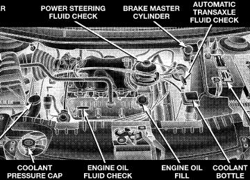
A hot engine cooling system is dangerous. You or others could be badly burned by steam or boiling coolant. You may want to call a service center if your vehicle overheats. If you decide to look under the hood yourself, see Section 7, Maintenance, of this manual. Follow the warnings under the Cooling System Pressure Cap paragraph.
WARNING!
† Getting under a jacked-up vehicle is dangerous. The vehicle could slip off the jack and fall on you. You could be crushed. Never get any part of your body under a vehicle that is on a jack. If you need to get under a raised vehicle, take it to a service center where it can be raised on a lift. † The jack is designed to use as a tool for changing tires only. The jack should not be used to lift the vehicle for service purposes. The vehicle should be jacked on a firm level surface only. Avoid ice or slippery areas.
Jack Location The jack and jack-handle are stowed behind the rear left side trim panel in the cargo area. Pull up on the lever to release the cover.
WHAT TO DO IN EMERGENCIES 293
Spare Tire Stowage The spare tire is stowed under the rear of the vehicle by means of a cable winch mechanism. To remove or stow the spare, use the jack handle to rotate the “spare tire drive” nut. The nut is located under the plastic cover at the center-rear of the cargo floor area, just inside the liftgate opening.
294 WHAT TO DO IN EMERGENCIES
Spare Tire Removal Fit the jack-handle over the drive nut. Rotate the nut to the left until the spare is on the ground with enough slack cable to allow you to pull the tire out from under the vehicle.
CAUTION!
The winch mechanism is designed for use with the jack handle only. Use of an air wrench or other power tools is not recommended and can damage the winch.
When the spare is clear, tilt the retainer at the end of the cable and pull it through the center of the wheel.
Preparations For Jacking Park the vehicle on a firm level surface, avoid ice or slippery areas, set the parking brake and place the gear selector in PARK. Turn OFF the ignition.
WARNING!
Do not attempt to change a tire on the side of the vehicle close to moving traffic. Pull far enough off the road to avoid the danger of being hit when operating the jack or changing the wheel.
WHAT TO DO IN EMERGENCIES 295
3. There are two jack engagement locations on each side of the body — see illustration.
† Turn on the Hazard Warning Flasher.
† Block both the front and rear of the wheel diagonally oppo- site the jacking position. For example, if changing the right front tire, block the left rear wheel. † Passengers should not remain in the vehicle when the
vehicle is being jacked.
Jacking Instructions
1. Remove the spare wheel, scissors jack and jack-handle from stowage. 2. Loosen (but do not remove) the wheel lug nuts by turning them to the left one turn while the wheel is still on the ground.
4. These locations are on the sill flange of the body and consist of a pair of downstanding tabs. The jack is to be located, engaging the flange, between the pair of tabs closest to the wheel to be changed. Place the wrench on the jack screw and turn to the right until the jack head is
296 WHAT TO DO IN EMERGENCIES
properly engaged in the described location. Do not raise the vehicle until you are sure the jack is securely engaged. 5. Raise the vehicle by turning the jack screw to the right, using the swivel wrench. Raise the vehicle only until the tire just clears the surface and enough clearance is obtained to install the spare tire. Minimum tire lift provides maximum stability.
WARNING!
Raising the vehicle higher than necessary can make the vehicle less stable. It could slip off the jack and hurt someone near it. Raise the vehicle only enough to remove the tire.
6. Remove the wheel lug nuts, for vehicles with wheel covers, remove the cover from the wheel by hand. Do not pry the wheel cover off. Then pull the wheel off the hub. 7. Install the spare wheel, for vehicles with wheel covers, align the notch in the wheel cover with the valve stem on the wheel. Install the cover on the wheel by hand only and install the wheel lug nuts with the cone shaped end of the nut toward the wheel. Lightly tighten the nuts. To avoid the risk of forcing the vehicle off the jack, do not tighten the lug nuts fully until the vehicle has been lowered. NOTE: Do not install the wheel cover on the compact spare. Do not use a hammer or force to install the wheel covers. 8. Lower the vehicle by turning the jack screw to the left. 9. Finish tightening the lug nuts. Push down on the wrench while tightening for increased leverage. Alternate
nuts until each nut has been tightened twice. Correct wheel nut tightness is 130 N·m (95 ft. lbs). If in doubt about the correct tightness, have them checked with a torque wrench by your dealer or at a service station. 10. Lower the jack to its fully closed position.
WARNING!
A loose tire or jack, thrown forward in a collision or hard stop could endanger the occupants of the ve- hicle. Always stow the jack parts and the spare tire in the places provided.
11. Secure the flat or spare tire as follows: † If your vehicle is equipped with cast aluminum wheels, the center cap of the wheel must be re- moved prior to flat tire stowage. Store the center cap inside the glove box or other storage compartment.
WHAT TO DO IN EMERGENCIES 297
† Turn the wheel so that the valve-stem is down. Slide the wheel retainer through the center of the wheel and position it properly across the wheel opening. † For convenience in checking the spare tire inflation, stow with the valve-stem toward the rear of the vehicle. † Using the jack-handle, rotate the drive nut to the right until the wheel is drawn into place against the underside of the vehicle. † Continue to rotate the nut until you hear the mecha- nism click three times. It cannot be overtightened. Push against the tire several times to be sure it is securely in place.
12. Stow jack and handle. 13. Check the tire pressure as soon as possible. Correct pressure as required.
298 WHAT TO DO IN EMERGENCIES
JUMP-STARTING PROCEDURES IF BATTERY IS LOW
WARNING!
Take care to avoid the radiator cooling fan whenever the hood is raised. It can start anytime the ignition switch is on. You can be hurt by the fan.
WARNING!
† Do not attempt to push or tow your vehicle to get it started. Vehicles equipped with an automatic trans- mission cannot be started this way. Unburned fuel could enter the catalytic converter and once the en- gine has started, ignite and damage the converter and vehicle. If the vehicle has a discharged battery, booster cables may be used to obtain a start from another vehicle. This type of start can be dangerous if done improperly, so follow this procedure carefully. † Battery fluid is a corrosive acid solution; do not allow battery fluid to contact eyes, skin or clothing. Don’t lean over battery when attaching clamps or allow the clamps to touch each other. If acid splashes in eyes or on skin, flush contaminated area immediately with large quantities of water. † A battery generates hydrogen gas which is flammable and explosive. Keep flame or spark away from the vent holes. Do not use a booster battery or any other booster source with an output that exceeds 12 volts.
1. Wear eye protection and remove any metal jewelry such as watch bands or bracelets that might make an inadvertent electrical contact. 2. When boost is provided by a battery in another vehicle, park that vehicle within booster cable reach and without letting the vehicles touch. Set the parking brake, place the automatic transmission in PARK and turn the ignition switch to the OFF position for both vehicles. 3. Turn off the heater, radio and all unnecessary electrical loads. 4. Connect one end of a jumper cable to the positive terminal of the discharged battery. Connect the other end of the same cable to the positive terminal of the booster battery.
WHAT TO DO IN EMERGENCIES 299
5. Connect the other cable, first to the negative terminal of the booster battery and then to the engine of the vehicle with the discharged battery. Make sure you have a good contact on the engine. 6. Start the engine in the vehicle which has the booster battery, let the engine idle a few minutes, then start the engine in the vehicle with the discharged battery. 7. When removing the jumper cables, reverse the above sequence exactly. Be careful of the moving belts and fan.
DRIVING ON SLIPPERY SURFACES
Acceleration Rapid acceleration on snow covered, wet, or other slip- pery surfaces may cause the front wheels to pull errati- cally to the right or left. This phenomenon occurs when there is a difference in the surface traction under the front (driving) wheels.
300 WHAT TO DO IN EMERGENCIES
WARNING!
Rapid acceleration on slippery surfaces is danger- ous. Unequal traction can cause sudden pulling of the front wheels. You could lose control of the vehicle and possibly have an accident. Accelerate slowly and carefully whenever there is likely to be poor traction (ice, snow, wet mud, loose sand, etc.).
Traction When driving on wet or slushy roads, it is possible for a wedge of water to build up between the tire and road surface. This is known as hydroplaning and may cause partial or complete loss of vehicle control and stopping ability. To reduce this possibility, the following precau- tions should be observed: 1. Slow down during rainstorms or when roads are slushy.
2. Slow down if road has standing water or puddles. 3. Replace tires when tread wear indicators first become visible. 4. Keep tires properly inflated. 5. Maintain sufficient distance between your vehicle and the vehicle in front to avoid a collision in a sudden stop.
FREEING A STUCK VEHICLE If your vehicle becomes stuck in mud, sand or snow, it can often be moved by a rocking motion. Turn your steering wheel right and left to clear the area around the front wheels. Then shift back and forth between Reverse and Drive. Usually the least accelerator pedal pressure to maintain the rocking motion without spinning the wheels is most effective.
WARNING!
Fast spinning tires can be dangerous. Forces gener- ated by excessive wheel speeds may cause tire dam- age or failure. A tire could explode and injure someone. Do not spin your vehicle’s wheels faster than 35 mph (55 km/h) when you are stuck. And don’t let anyone near a spinning wheel, no matter what the speed.
CAUTION!
Racing the engine or spinning the wheels too fast may lead to transmission overheating and failure. It can also damage the tires. Do not spin the wheels above 35 mph (55 km/h).
WHAT TO DO IN EMERGENCIES 301
TOWING A DISABLED VEHICLE With Ignition Key Front Wheel Drive Your vehicle may be towed under the following condi- tions: The gear selector must be in NEUTRAL, the dis- tance to be traveled must not exceed 100 miles (160 km), and the towing speed must not exceed 44 mph (72 km/h). Exceeding these towing limits may cause a transmission geartrain failure. If the transaxle is not operative, or if the vehicle is to be towed more than 100 miles (160 km), the vehicle must be towed with the front wheels off the ground. All Wheel Drive — If Equipped Your vehicle may be towed under the following condi- tions: The gear selector must be in NEUTRAL, the dis- tance to be traveled must not exceed 100 miles (160 km), the towing speed must not exceed 44 mph (72 km/h), and both front and rear wheels must be on the ground. If your vehicle must be towed farther or at a higher rate of speed, it must be transported on a flat bed truck.
302 WHAT TO DO IN EMERGENCIES
CAUTION!
† Do not attempt to tow this vehicle from the front with sling type towing equipment. Damage to the front fascia will result. † Always use wheel lift equipment when towing from the front. The only other approved method of towing is with a flat bed truck. † Do not tow the vehicle from the rear. Damage to the rear sheet metal, liftgate and fascia will occur. † Do not push or tow this vehicle with another vehicle as damage to the bumper fascia and trans- axle may result. † If the vehicle being towed requires steering, the ignition switch must be in the OFF position, not in the LOCK or ACCESSORY positions.
If it is necessary to use the accessories while being towed (wipers, defrosters, etc.), the key must be in the ON position, not the ACCESSORY position. Make certain the transaxle remains in NEUTRAL. Without The Ignition Key Special care must be taken when the vehicle is towed with the ignition in the LOCK position. The only ap- proved method of towing with out the ignition key is with a flat bed truck. Proper towing equipment is neces- sary to prevent damage to the vehicle. TOWING THIS VEHICLE BEHIND ANOTHER VEHICLE (Flat towing with all four wheels on the ground) Flat towing of vehicles equipped with an automatic transaxle, is only permitted within the limitations de- scribed in this section.
TOWING THIS VEHICLE BEHIND ANOTHER VEHICLE WITH A TOW DOLLEY The manufacture does not recommend that you tow an All-Wheel Drive (AWD) or front wheel drive vehicle on a tow dolley. Vehicle damage may occur.
WHAT TO DO IN EMERGENCIES 303
MAINTAINING YOUR VEHICLE
CONTENTS
m 3.3L/3.8L Engines . . . . . . . . . . . . . . . . . . . . . . 308
m Onboard Diagnostic System — OBD II . . . . . . . . 309
m Emissions Inspection And MaintenancePrograms
. . . . . . . . . . . . . . . . . . . . . . . . . . . . 310
m Replacement Parts . . . . . . . . . . . . . . . . . . . . . . 311
m Dealer Service . . . . . . . . . . . . . . . . . . . . . . . . . 311
m Maintenance Procedures . . . . . . . . . . . . . . . . . . 312
N Engine Oil . . . . . . . . . . . . . . . . . . . . . . . . . . 313
N Engine Oil Filter . . . . . . . . . . . . . . . . . . . . . . 316N Drive Belts — Check Condition And Tension . . 316
N Spark Plugs . . . . . . . . . . . . . . . . . . . . . . . . . 317
N Engine Air Cleaner Filter . . . . . . . . . . . . . . . . 317
N Engine Fuel Filter . . . . . . . . . . . . . . . . . . . . . 318
N Catalytic Converter . . . . . . . . . . . . . . . . . . . . 318
N Maintenance-Free Battery . . . . . . . . . . . . . . . . 319
N Air Conditioner . . . . . . . . . . . . . . . . . . . . . . 321
N Power Steering — Fluid Check . . . . . . . . . . . . 322
N Front Suspension Ball Joints . . . . . . . . . . . . . . 323306 MAINTAINING YOUR VEHICLE
N Steering Shaft Seal . . . . . . . . . . . . . . . . . . . . 323
N Steering Linkage . . . . . . . . . . . . . . . . . . . . . . 323
N Drive Shaft Universal Joints . . . . . . . . . . . . . . 323
N Body Lubrication . . . . . . . . . . . . . . . . . . . . . 324
N Windshield Wiper Blades . . . . . . . . . . . . . . . . 324
N Windshield And Rear Window Washers . . . . . 324
N Exhaust System . . . . . . . . . . . . . . . . . . . . . . 325
N Cooling System . . . . . . . . . . . . . . . . . . . . . . . 326
N Hoses And Vacuum/Vapor Harnesses . . . . . . . 331
N Brakes . . . . . . . . . . . . . . . . . . . . . . . . . . . . . 331
N Master Cylinder — ABS Brakes Brake FluidLevel Check . . . . . . . . . . . . . . . . . . . . . . . . . 333
N Fuel System Hoses . . . . . . . . . . . . . . . . . . . . 334N Automatic Transmission . . . . . . . . . . . . . . . . 335
N All Wheel Drive (AWD) . . . . . . . . . . . . . . . . . 337
N Front And Rear Wheel Bearings . . . . . . . . . . . 339
N Appearance Care And ProtectionFrom Corrosion . . . . . . . . . . . . . . . . . . . . . . 339
N Cleaning The Instrument Panel And Underseat
Cup Holders
. . . . . . . . . . . . . . . . . . . . . . . . 343
m Integrated Power Module (IPM) . . . . . . . . . . . . 344
m Vehicle Storage . . . . . . . . . . . . . . . . . . . . . . . . 345
m Replacement Light Bulbs . . . . . . . . . . . . . . . . . 346
m Bulb Replacement . . . . . . . . . . . . . . . . . . . . . . 347
N Headlights . . . . . . . . . . . . . . . . . . . . . . . . . . 347
N Front Park/Turn Signal AndSidemarker Lights . . . . . . . . . . . . . . . . . . . . . 348
N Front Fog Light N Rear Tail, Stop, Turn Signal, Side Marker And
. . . . . . . . . . . . . . . . . . . . . . 349
Back-Up Lights . . . . . . . . . . . . . . . . . . . . . . . 350
N Center High Mounted Stop Light (CHMSL) . . . 351
N License Light . . . . . . . . . . . . . . . . . . . . . . . . 351MAINTAINING YOUR VEHICLE 307
m Fluid Capacities . . . . . . . . . . . . . . . . . . . . . . . . 351
m Recommended Fluids, Lubricants AndGenuine Parts . . . . . . . . . . . . . . . . . . . . . . . . . 352
N Engine . . . . . . . . . . . . . . . . . . . . . . . . . . . . . 352
N Chassis . . . . . . . . . . . . . . . . . . . . . . . . . . . . 353308 MAINTAINING YOUR VEHICLE
3.3L/3.8L ENGINES
ONBOARD DIAGNOSTIC SYSTEM — OBD II Your vehicle is equipped with a sophisticated onboard diagnostic system called OBD II. This system monitors the performance of the emissions, engine, and automatic transmission control systems. When these systems are operating properly, your vehicle will provide excellent performance and fuel economy, as well as engine emis- sions well within current government regulations. If any of these systems require service, the OBD II system will turn on the “Malfunction Indicator Light.” It will also store diagnostic codes and other information to assist your service technician in making repairs. Al- though your vehicle will usually be drivable and not need towing, see your dealer for service as soon as possible.
MAINTAINING YOUR VEHICLE 309
CAUTION!
Prolonged driving with the “Malfunction Indicator Light” on could cause further damage to the emis- sion control system. It could also affect fuel economy and driveability. The vehicle must be serviced before any emissions tests can be performed. If the “Malfunction Indicator Light” is flashing while the engine is running, severe catalytic con- verter damage and power loss will soon occur. Im- mediate service is required.
310 MAINTAINING YOUR VEHICLE
EMISSIONS INSPECTION AND MAINTENANCE PROGRAMS In some localities, it may be a legal requirement to pass an inspection of your vehicle’s emissions control system. Failure to pass could prevent vehicle registration.
For states which have an I/M (Inspection and Maintenance) requirement, this check verifies the following: the MIL (Malfunction Indicator Lamp) is functioning and is not on when the engine is running, and that the OBD (On Board Diagnostic) system is ready for testing. Normally, the OBD system will be ready. The OBD system may not be ready if your vehicle was recently serviced, if you recently had a dead battery, or a battery replacement. If the OBD system should be determined not ready for the I/M test, your vehicle may fail the test.
Your vehicle has a simple ignition key actuated test which you can use prior to going to the test station. To check if your vehicle’s OBD system is ready, you must do the following: 1. Insert your ignition key into the ignition switch. 2. Turn the ignition to the ON position, but do not crank or start the engine. 3. If you crank or start the engine, you will have to start this test over. 4. As soon as you turn your key to the ON position, you will see your MIL symbol come on as part of a normal bulb check. 5. Approximately 15 seconds later, one of two things will happen:
a. The MIL will flash for about 10 seconds and then return to being fully illuminated until you turn off the
ignition key or start the engine. This means that your vehicle’s OBD system is not ready and you should not proceed to the I/M station. b. The MIL will not flash at all and will remain fully illuminated until you turn off the ignition key or start the engine. This means that your vehicle’s OBD system is ready and you can proceed to the I/M station.
If your OBD system is not ready, you should see your authorized dealer or repair facility. If your vehicle was recently serviced or had a battery failure or replacement, you may need to do nothing more than drive your vehicle as you normally would in order for your OBD system to update. A recheck with the above test routine may then indicate that the system is now ready. Regardless of whether your vehicle’s OBD system is ready or not ready, if the MIL symbol is illuminated during normal vehicle operation, you should have your
MAINTAINING YOUR VEHICLE 311
vehicle serviced before going to the I/M station. The I/M station can fail your vehicle because the MIL symbol is on with the engine running.
REPLACEMENT PARTS Use of genuine Mopart parts for normal/scheduled maintenance and repairs is highly recommended to in- sure the designed performance. Damage or failures caused by the use of non-Mopart parts for maintenance and repairs will not be covered by the manufacturer’s warranty.
DEALER SERVICE Your dealer has the qualified service personnel, special tools and equipment to perform all service operations in an expert manner. Service Manuals are available which include detailed service information for your vehicle. Refer to these manuals before attempting any procedure yourself.
312 MAINTAINING YOUR VEHICLE
NOTE: systems can result against you.
Intentional tampering with emissions control in civil penalties being assessed
WARNING!
You can be badly injured working on or around a motor vehicle. Do only that service work for which you have the knowledge and the proper equipment. If you have any doubt about your ability to perform a service job, take your vehicle to a competent mechanic.
MAINTENANCE PROCEDURES The pages that follow contain the required maintenance services determined by the engineers who designed your vehicle. Besides the maintenance items for which there are fixed maintenance intervals, there are other items that should operate satisfactorily without periodic maintenance. However, if a malfunction of these items does occur, it could adversely affect the engine or vehicle performance. These items should be inspected if a malfunction is observed or suspected.
Engine Oil
Checking Oil Level To assure proper engine lubrication, the engine oil must be maintained at the correct level. Check the oil level at regular intervals, such as every fuel stop. The best time to check the engine oil level is about 5
minutes after a fully warmed engine is shut off or before starting the engine after it has sat overnight. Checking the oil while the vehicle is on level ground will improve the accuracy of the oil level readings. Maintain the oil level between the MIN and MAX markings on the dipstick. Adding one quart of oil when the reading is at the MIN mark will result in a MAX reading on these engines.MAINTAINING YOUR VEHICLE 313
CAUTION!
Overfilling or underfilling will cause oil aeration or loss of oil pressure. This could damage your engine.
314 MAINTAINING YOUR VEHICLE
Change Engine Oil Road conditions and your kind of driving affects the interval at which your oil should be changed. Check the following list to see if any apply to you. † Day or night temperatures are below 32°F (0°C). † Stop and Go driving. † Extensive engine idling. † Driving in dusty conditions. † Short trips of less than 10 miles (16 km). † More than 50% of your driving is at sustained high † Trailer towing. † Taxi, Police or delivery service (commercial service). † Off-Road or desert operation.
speeds during hot weather, above 90°F (32°C).
If ANY of these apply to you, then change your engine oil every 3,000 miles (4 800 km) or 3 months, whichever comes first. If none of these apply to you, then change your engine oil every 6,000 miles (10 000 km) or 6 months whichever comes first. NOTE: Under no circumstances should oil change in- tervals exceed 6,000 miles (10 000 km) or 6 months whichever comes first. Engine Oil Selection For best performance and maximum protection under all types of operating conditions, the manufacture only recommends engine oils that are API certified and meet the requirements of DaimlerChrysler Material Standard MS-6395. Use Mopar or an equivalent oil meeting the specification MS-6395.
American Petroleum Institute (API) Engine Oil Identification Symbol
This symbol means that the oil has been certified by the American Petroleum Institute (API). The manufacture only recommends API Certified engine oils that meet of DaimlerChrysler Material Stan- dard MS-6395. Use Mopar or an equivalent oil meeting the specifi-
requirements
the
cation MS-6395. Engine Oil Viscosity Chart The proper SAE viscosity grade of engine oil should be selected based on the following recommendation and be within the operating temperature shown in the engine oil viscosity chart.
MAINTAINING YOUR VEHICLE 315
† SAE 5W-30 engine oil is preferred. SAE 5W-30 engine oils improve low temperature starting and helps ve- hicle fuel economy.
Lubricants which do not have both, the engine oil certi- fication mark and the correct SAE viscosity grade num- ber should not be used.
316 MAINTAINING YOUR VEHICLE
Synthetic Engine Oils There are a number of engine oils being promoted as either synthetic or semi-synthetic. If you chose to use such a product, use only those oils that meet the Ameri- can Petroleum Institute (API) and SAE viscosity stan- dard. Follow the service schedule that describes your driving type. Materials Added to Engine Oil The manufacture strongly recommends against the addi- tion of any additives (other than leak detection dyes) to the engine oil. Engine oil is an engineered product and it’s performance may be impaired by supplemental ad- ditives. Disposing of Used Engine Oil And Oil Filters Care should be taken in disposing of used engine oil and oil filters from your vehicle. Used oil and oil filters, indiscriminately discarded, can present a problem to the environment. Contact your dealer, service station, or
governmental agency for advice on how and where used oil and oil filters can be safely discarded in your area. Engine Oil Filter The engine oil filter should be replaced at every engine oil change. Engine Oil Filter Selection The manufacturer’s engines have a full-flow type oil filter. Use a filter of this type for replacement. The quality of replacement filters varies considerably. Only high quality filters should be used to assure most efficient service. Mopar Engine Oil Filters are a high quality oil filter and are recommended. Drive Belts — Check Condition and Tension At the mileage indicated in the maintenance schedule, all belts should be checked for condition and proper tension. Improper belt tension can cause belt slippage and failure.
Belts should be inspected for evidence of cuts, cracks, or glazing, and replaced if there is indication of damage which could result in belt failure. If adjustment is re- quired, see your authorized dealer for service. Low generator belt tension can cause battery failure. A special tool is required to properly measure tension and to restore belt tension to factory specifications. Also check belt routing to make sure there is no interfer- ence between the belts and other engine components. Spark Plugs Spark plugs must fire properly to assure engine perfor- mance and emission control. New plugs should be in- stalled at the specified mileage. The entire set should be replaced if there is any malfunction due to a faulty spark plug, malfunctioning spark plugs can damage the cata- lytic converter. For proper type of replacement spark plugs, refer to the “Vehicle Emission Control Informa- tion” label in the engine compartment.
MAINTAINING YOUR VEHICLE 317
Engine Air Cleaner Filter Under normal driving conditions, replace the air filter at the intervals shown on Schedule “A”. If, however, you drive the vehicle frequently under dusty or severe con- ditions, the filter element should be inspected periodi- cally and replaced if necessary at the intervals shown on Schedule “B”.
WARNING!
The air cleaner can provide a measure of protection in the case of engine backfire. Do not remove the air cleaner unless such removal is necessary for repair or maintenance. Make sure that no one is near the engine compartment before starting the vehicle with the air cleaner removed. Failure to do so can result in serious personal injury.
318 MAINTAINING YOUR VEHICLE
Engine Fuel Filter A plugged fuel filter can cause stalling, limit the speed at which a vehicle can be driven or cause hard starting. Should an excessive amount of dirt accumulate in the fuel tank, filter replacement may be necessary. Catalytic Converter The catalytic converter requires the use of unleaded fuel only. Leaded gasoline will destroy the effectiveness of the catalyst as an emission control device. Under normal operating conditions, the catalytic con- verter will not require maintenance. However, it is im- portant to keep the engine properly tuned to assure proper catalyst operation and prevent possible catalyst damage.
CAUTION!
Damage to the catalytic converter can result if your vehicle is not kept in proper operating condition. In the event of engine malfunction, particularly involv- ing engine misfire or other apparent loss of perfor- mance, have your vehicle serviced promptly. Contin- ued operation of your vehicle with a severe malfunction could cause the converter to overheat, resulting in possible damage to the converter and the vehicle.
NOTE: systems can result against you.
Intentional tampering with emissions control in civil penalties being assessed
WARNING!
A hot exhaust system can start a fire if you park over materials that can burn. Such materials might be grass or leaves coming into contact with your ex- haust system. Do not park or operate your vehicle in areas where your exhaust system can contact any- thing that can burn.
In unusual situations involving grossly malfunctioning engine operation, a scorching odor may indicate severe and abnormal catalyst overheating. If this occurs, the vehicle should be stopped, the engine shut off and the vehicle allowed to cool. Thereafter, service, including a tune-up to manufacturer’s specifications, should be ob- tained immediately.
MAINTAINING YOUR VEHICLE 319
To minimize the possibility of catalyst damage: † Do not shut off the engine or interrupt the ignition when the transmission is in gear and the vehicle is in motion. † Do not try to start engine by pushing or towing the † Do not idle the engine with any spark plug wires disconnected or removed, such as when diagnostic testing, or for prolonged periods during very rough idling or malfunctioning operating conditions.
vehicle.
Maintenance-Free Battery The top of the MAINTENANCE-FREE battery is perma- nently sealed. You will never have to add water, nor is periodic maintenance required.
320 MAINTAINING YOUR VEHICLE
WARNING!
Battery fluid is a corrosive acid solution and can burn or even blind you. Don’t allow battery fluid to contact your eyes, skin or clothing. Don’t lean over a battery when attaching clamps. If acid splashes in eyes or on skin, flush the area immediately with large amounts of water. Battery gas is flammable and explosive. Keep flame or sparks away from the battery. Don’t use a booster battery or any other booster source with an output greater than 12 volts. Don’t allow cable clamps to touch each other. Battery posts, terminals and related accessories con- tain lead and lead compounds. Wash hands after handling.
CAUTION!
It is essential when replacing the cables on the battery that the positive cable is attached to the positive post and the negative cable is attached to the negative post. Battery posts are marked positive (+) and negative (-) and identified on the battery case. Cable clamps should be tight on the terminal posts and free of corrosion. If a “fast charger” is used while battery is in vehicle, disconnect both vehicle battery cables before con- necting the charger to battery. Do not use a “fast charger” to provide starting voltage.
Air Conditioner For best possible performance, your air conditioner should be checked and serviced by an Authorized Dealer at the start of each warm season. This service should include cleaning of the condenser fins and a system performance check. Drive belt tension should also be checked at this time.
MAINTAINING YOUR VEHICLE 321
WARNING!
injuring
you. Other
† Use only refrigerants approved by the manufac- turer for your air conditioning system. Some un- approved refrigerants are flammable and can ex- plode, unapproved refrigerants can cause the system to fail, requiring costly repairs. † Never add air conditioning refrigerant to correct a non-cooling problem unless pressure gauges are connected to the system by a certified technician. Lack of cooling could be due to a restriction and adding refrigerant may cause a dangerous pres- sure rise and you could be injured.
322 MAINTAINING YOUR VEHICLE
Refrigerant Recovery And Recycling The air conditioning system of your vehicle contains R-134a, a refrigerant that does not deplete the ozone layer in the upper atmosphere. The manufacturer recommends that air conditioning service be done by facilities using refrigerant recycling and recovery equipment that meets SAE standard J1991. A/C Air Filter The filter access door is located under the instrument panel on the passenger side. To replace the filter slide the lock toward the rear of the vehicle (unlock position). Remove the access door and pull the filter downward. When installing a new filter, ensure its proper orienta- tion. Align the black arrow on the bottom of the filter frame with the direction of airflow (away from the blower motor and towards the center of the car). Recommended Filter Replacement Interval – 12,000
Miles (19 000 km)Power Steering — Fluid Check Checking the power steering fluid level at a defined service interval is not required. The fluid should only be checked if a leak is suspected, abnormal noises are apparent, and/or the system is not functioning as antici- pated. Coordinate inspection efforts through a certified DaimlerChrysler Dealership.9
WARNING!
Fluid level should be checked on a level surface and with the engine off to prevent injury from moving parts and to insure accurate fluid level reading. Do not overfill. Use only manufacturers recommended power steering fluid.
If necessary, add fluid to restore to the proper indicated level. With a clean cloth, wipe any spilled fluid from all surfaces. Refer to Recommended Fluids, Lubricants, and Genuine Parts for correct fluid type. Front Suspension Ball Joints The front suspension ball joints are permanently sealed. No regular maintenance is required for these compo- nents. Steering Shaft Seal The steering shaft seal, at the point where the shaft passes through the bulkhead, is lubricated when it is installed. If the seal becomes noisy when the steering shaft is turned, it should be lubricated. Use only manufacturers recom- mended lubricant, refer to Recommended Fluids, Lubri- cants and Genuine Parts for correct lubricant type.
MAINTAINING YOUR VEHICLE 323
Steering Linkage The tie rod end ball joints are permanently lubricated and do not require periodic maintenance. Drive Shaft Universal Joints Your vehicle has constant velocity universal joints. Peri- odic lubrication of these joints is not required. However, the joint boots should be inspected for external leakage or damage when other maintenance is performed. If leakage or damage is evident, the universal joint boot and grease should be replaced immediately. Continued operation could result in failure of the univer- sal joint due to water and dirt contamination of the grease. This would require complete replacement of the joint assembly.
324 MAINTAINING YOUR VEHICLE
Body Lubrication Locks and all body pivot points, including such items as seat tracks, doors, liftgate, sliding doors and hood hinges, should be lubricated periodically to assure quiet, easy operation and to protect against rust and wear. Prior to the application of any lubricant, the parts concerned should be wiped clean to remove dust and grit; after lubricating excess oil and grease should be removed. Particular attention should also be given to hood latching components to insure proper function. When performing other underhood services, the hood latch, release mecha- nism and safety catch should be cleaned and lubricated. The external lock cylinders should be lubricated twice a year, preferably in the fall and spring. Apply a small amount of a high quality lubricant such as Mopart Lock Cylinder Lubricant directly into the lock cylinder.
Windshield Wiper Blades The rubber edges of the wiper blades and the windshield should be cleaned periodically with a sponge or soft cloth and a mild nonabrasive cleaner. This will remove accu- mulations of salt or road film. Operation of the wipers on dry glass for long periods may cause deterioration of the wiper blades. Always use washer fluid when using the wipers to remove salt or dirt from a dry windshield. Avoid using the wiper blades to remove frost or ice from the windshield. Keep the blade rubber out of contact with petroleum products such as engine oil, gasoline, etc. Windshield and Rear Window Washers The fluid reservoir for the windshield washers and the rear window washer is shared. It is located in the engine compartment and should be checked for fluid level at regular intervals. Fill the reservoir with windshield
washer solvent (not radiator antifreeze) and operate the system for a few seconds to flush out the residual water. The washer fluid reservoir will hold a full gallon of fluid when the Low Washer Fluid Light illuminates.
MAINTAINING YOUR VEHICLE 325
Exhaust System The best protection against carbon monoxide entry into the vehicle body is a properly maintained engine exhaust system. Whenever a change is noticed in the sound of the exhaust system, when exhaust fumes can be detected inside the vehicle, or when the underside or rear of the vehicle is damaged, have a competent mechanic inspect the com- plete exhaust system and adjacent body areas for broken, damaged, deteriorated, or mispositioned parts. Open seams or loose connections could permit exhaust fumes to seep into the passenger compartment. In addition, inspect the exhaust system each time the vehicle is raised for lubrication or oil change. Replace as required.
326 MAINTAINING YOUR VEHICLE
WARNING!
Exhaust gases can injure or kill. They contain carbon monoxide (CO) which is colorless and odorless. Breathing it can make you unconscious and can eventually poison you. To avoid breathing CO, fol- low the preceding safety tips.
Cooling System
Inspection
WARNING!
† When working near the radiator cooling fan, turn the ignition key to the OFF position. The fan is temperature controlled and can start at any time when the ignition key is in the ON position. † You or others can be badly burned by hot coolant or steam from your radiator. If you see or hear steam coming from under the hood, don’t open the hood until the radiator has had time to cool. Never try to open a cooling system pressure cap when the radiator is hot.
Coolant Checks Coolant protection checks should be made every 12
months (prior to the onset of freezing weather, where applicable). If coolant is dirty or rusty in appearance, the system should be drained, flushed and refilled with fresh coolant. Check the front of the A/C condenser for any accumulation of bugs, leaves, etc. If dirty, clean by removing the upper grill support and gently spraying water from a garden hose vertically down the face of the condenser. Check the coolant recovery bottle tubing for brittle rub- ber, cracking, tears, cuts and tightness of the connection at the bottle and radiator. Inspect the entire system for leaks. With the engine at normal operating temperature (but not running), check the coolant pressure cap for proper vacuum sealing by draining a small amount of coolantMAINTAINING YOUR VEHICLE 327
from the radiator drain cock. If the cap is sealing prop- erly, the coolant will begin to drain from the coolant recovery bottle. DO NOT REMOVE THE COOLANT PRESSURE CAP WHEN THE COOLING SYSTEM IS HOT. Cooling System — Drain, Flush and Refill At the intervals shown in the maintenance schedules, the system should be drained, flushed and refilled. If the solution is dirty or contains a considerable amount of sediment, clean and flush with a reliable cooling system cleaner. Follow with a thorough rinsing to remove all deposits and chemicals. Properly dispose of old antifreeze solution. Selection Of Coolant Use only the manufacturers recommended coolant, refer to Recommended Fluids, Lubricants and Genuine Parts for correct coolant type.
328 MAINTAINING YOUR VEHICLE
CAUTION!
Mixing of coolants other than specified (non- HOAT), may result in engine damage that may not be covered under the new vehicle warranty, and decreased corrosion protection. If a non-HOAT cool- ant is introduced into the cooling system in an emergency, it should be replaced with the specified coolant as soon as possible. Do not use plain water alone or alcohol base anti- freeze products. Do not use additional rust inhibi- tors or antirust products, as they may not be compat- ible with the radiator coolant and may plug the radiator. This vehicle has not been designed for use with Propylene Glycol based coolants. Use of Propylene Glycol based coolants is not recommended.
Adding Coolant When adding coolant, or refilling the system, a minimum of 50% solution of ethylene glycol antifreeze coolant in water should be used. Higher concentrations (not to exceed 70%) are required if temperatures below 237°F (238°C) are anticipated. Use only high purity water such as distilled or deionized water when mixing the water/antifreeze solution. The use of lower quality water will reduce the amount of corrosion protection in the engine cooling system. Please note that it is the owner’s responsibility to main- tain the proper level of protection against freezing ac- cording to the temperatures occurring in the area where the vehicle is operated. NOTE: Mixing coolant types will decrease the life of the engine coolant and will require more frequent coolant changes.
Coolant Pressure Cap The coolant pressure cap must be fully tightened to prevent loss of coolant, and to insure that coolant will return to the radiator from the coolant recovery bottle. The coolant pressure cap should be inspected and cleaned if there is any accumulation of foreign material on the sealing surfaces.
WARNING!
The warning words “DO NOT OPEN HOT” on the coolant pressure cap are a safety precaution. Never add coolant to the radiator when the engine is overheated. Do not loosen or remove the coolant pressure cap to cool an overheated engine. Heat causes pressure to build up in the cooling system. To prevent scalding or injury, do not remove the coolant pressure cap while the system is hot or under pressure.
MAINTAINING YOUR VEHICLE 329
Disposal of Used Engine Coolant Used ethylene glycol based engine coolant is a regulated substance requiring proper disposal. Check with your local authorities to determine the disposal rules for your community. To prevent ingestion by animals or children do not store ethylene glycol based engine coolant in open containers or allow it to remain in puddles on the ground. If ingested by a child, contact a physician immediately. Clean up any ground spills immediately. Coolant Level The coolant recovery bottle provides a quick visual method for determining that the coolant level is ad- equate. With the engine cold, the level of the coolant in the coolant recovery bottle should be between the “MAX” and “MIN” marks. The radiator normally re- mains completely full, so there is no need to remove the radiator cap except for checking coolant freeze point or replacement with new antifreeze coolant. Your service attendant should be advised of this. So long as the engine
330 MAINTAINING YOUR VEHICLE
operating temperature is satisfactory, the coolant recov- ery bottle need only be checked once a month. When additional coolant is needed to maintain the proper level, it should be added to the coolant recovery bottle. Do not overfill. Points to Remember NOTE: When the vehicle is stopped after a few miles of operation, you may observe vapor coming from the front of the engine compartment. This is normally a result of moisture from rain, snow, or high humidity accumulat- ing on the radiator and being vaporized when the thermostat opens, allowing hot water to enter the radia- tor. If an examination of your engine compartment shows no evidence of radiator or hose leaks, the vehicle may be safely driven. The vapor will soon dissipate. † Do not overfill the coolant recovery bottle.
† Check coolant freeze point in the radiator and in the coolant recovery bottle. If antifreeze needs to be added, contents of coolant recovery bottle must also be protected against freezing. † If frequent coolant additions are required, or if the level in the coolant recovery bottle does not drop when the engine cools, the cooling system should be pres- sure tested for leaks. † Maintain coolant concentration at 50% ethylene glycol antifreeze (minimum) in water for proper corrosion protection of your engine which contains aluminum components. † Make sure that the radiator and coolant recovery bottle overflow hoses are not kinked or obstructed. † Keep the front of the radiator clean. If your vehicle is equipped with air conditioning, keep the front of the condenser clean, also.
† Do not change the thermostat for summer or winter operation. If replacement is ever necessary, install ONLY the correct type thermostat. Other designs may result in unsatisfactory cooling performance. † Increasing engine speed at idle does not reduce cool- ant temperature! Put transmission in NEUTRAL and let engine idle at normal engine idle speed.
Hoses And Vacuum/Vapor Harnesses Inspect surfaces of hoses and nylon tubing for evidence of heat and mechanical damage. Hard or soft spots, brittle rubber, cracking, tears, cuts, abrasions, and exces- sive swelling indicate deterioration of the rubber. Pay particular attention to those hoses nearest to high heat sources such as the exhaust manifold. Inspect hose routing to be sure hoses do not come in contact with any heat source or moving component which may cause heat damage or mechanical wear.
MAINTAINING YOUR VEHICLE 331
Insure nylon tubing in these areas has not melted or collapsed. Inspect all hose connections such as clamps and cou- plings to make sure they are secure and no leaks are present. Components should be replaced immediately if there is any evidence of wear or damage that could cause failure. Brakes In order to assure brake system performance, all brake system components should be inspected periodically. Suggested service intervals can be found in the Mainte- nance Schedules.
332 MAINTAINING YOUR VEHICLE
WARNING!
Riding the brakes can lead to brake failure and possibly an accident. Driving with your foot resting or riding on the brake pedal can result in abnormally high brake temperatures, excessive lining wear, and possible brake damage. You wouldn’t have your full braking capacity in an emergency.
Brake And Power Steering Hoses When the vehicle is serviced for scheduled maintenance, inspect surface of hoses and nylon tubing for evidence of heat and mechanical damage. Hard and brittle rubber, cracking, tears, cuts, abrasion, and excessive swelling indicate deterioration of the rubber. Particular attention should be made to examining those hose surfaces nearest to high heat sources, such as the exhaust manifold.
Insure nylon tubing in these areas has not melted or collapsed. Inspect all hose connections such as clamps and cou- plings to make sure they are secure and no leaks are present. NOTE: Often, fluid such as oil, power steering fluid, and brake fluid are used during assembly plant opera- tions to facilitate the assembly of hoses to couplings. Therefore, oil wetness at the hose-coupling area is not necessarily an indication of leakage. Actual dripping of hot fluid when systems are under pressure (during vehicle operation), should be noted before hose is re- placed based on leakage. Inspection of brake hoses should be performed NOTE: whenever the brake system is serviced and every engine oil change. Inspect hydraulic brake hoses for surface cracking, scuffing, or worn spots. If there is any evidence of cracking, scuffing, or worn spots, the hose should be
replaced immediately! Eventual deterioration of the hose can take place resulting in a possibility of a burst failure.
WARNING!
Worn brake hoses can burst and cause brake failure. You could have an accident. If you see any signs of cracking, scuffing, or worn spots, have the brake hoses replaced immediately.
Master Cylinder — ABS Brakes Brake Fluid Level Check The fluid level in the master cylinder should be checked when performing underhood services, or immediately if the brake system warning light indicates system failure. Clean the top of the master cylinder area before removing the cap. Add fluid to bring the level up to the top of the “FULL” mark on the side of the master cylinder reservoir.
MAINTAINING YOUR VEHICLE 333
Overfilling of fluid is not recommended because it may cause leaking in the system. Add enough fluid to bring the level up to the require- ments described on the brake fluid reservoir. With disc brakes, fluid level can be expected to fall as the brake pads wear. However, low fluid level may be caused by a leak and a checkup may be needed. Use only manufacturers recommended brake fluid, refer to Recommended Fluids, Lubricants and Genuine Parts for correct fluid type.
WARNING!
Use of brake fluid that may have a lower initial boiling point or unidentified as to specification, may result in sudden brake failure during hard pro- longed braking. You could have an accident.
334 MAINTAINING YOUR VEHICLE
WARNING!
Overfilling the brake fluid reservoir can result in spilling brake fluid on hot engine parts and the brake fluid catching fire.
Use only brake fluid that has been in a tightly closed container to avoid contamination from foreign matter or moisture.
CAUTION!
Do not allow petroleum base fluid to contaminate the brake fluid — all brake seal components could be damaged causing partial or complete brake fail- ure.
Fuel System Hoses Electronic Fuel Injection high pressure fuel systems are designed with hoses and clamps which have unique material characteristics to provide adequate sealing and resist attack by deteriorated gasoline. You are urged to use only the manufacturers specified hoses and clamps, or their equivalent in material and specification, in any fuel system servicing. It is manda- tory to replace all clamps that have been loosened or removed during service. Care should be taken in install- ing new clamps to insure they are properly torqued.
Automatic Transmission The automatic transmission and differential assembly are contained within a single housing. All automatic transmissions are equipped with a conven- tional filler tube and dipstick. If fluid is added, it should be added through the dipstick hole in the case. The dipstick is located just behind the radiator, lower right side. Selection of Lubricant It is important that the proper lubricant is used in the transmission to assure optimum transmission perfor- mance. Use only manufacturers recommended transmis- sion fluid, refer to Recommended Fluids, Lubricants and Genuine Parts for correct fluid type. It is important that the transmission fluid be maintained at the prescribed level using the recommended fluid.
MAINTAINING YOUR VEHICLE 335
CAUTION!
Using a transmission fluid other than the manufac- turers recommended fluid may cause deterioration in transmission shift quality and/or torque converter shudder. Using a transmission fluid other than the manufacturers recommended fluid will result in more frequent fluid and filter changes. Refer to Recommended Fluids, Lubricants and Genuine Parts for correct fluid type.
336 MAINTAINING YOUR VEHICLE
Procedure For Checking Fluid Level The fluid level in the automatic transmission should be checked whenever the vehicle is serviced. Operation with an improper fluid level will greatly reduce the life of the transmission and of the fluid. To properly check the automatic transmission fluid level, the following procedure must be used: 1. The vehicle must be on level ground. 2. The engine should be running at curb idle speed for a minimum of 60 seconds. 3. Fully apply parking brake. 4. Place the gear selector momentarily in each gear position ending with the lever in P (PARK). Wipe the area around the dipstick clean to eliminate the possibility of dirt entering the transmission.
5. Remove the dipstick and determine if the fluid is hot or warm. Hot fluid is approximately 180°F (82°C), which is the normal operating temperature after the vehicle has been driven at least 15 miles (24 km). The fluid cannot be comfortably held between the finger tips. Cold is when the fluid is below 27°C (80°F). 6. Wipe the dipstick clean and reinsert until seated. Remove dipstick and note reading.
a. If the fluid is hot, the reading should be in the crosshatched area marked “HOT” (between the upper two holes in the dipstick). b. If the fluid is cold, the fluid level should be between the lower two holes in the area marked “COLD”.
If the fluid level indicates low, add sufficient fluid to bring to the proper level.
CAUTION!
Do not overfill. Dirt and water in the transmission can cause serious damage. To prevent dirt and water from entering the transmission after checking or replenishing fluid, make certain that the dipstick cap is reseated properly.
Fluid and Filter Changes Automatic transmission fluid should be changed on all transmissions as follows: Normal Usage — No change necessary Severe Usage (fluid and filter) — 60,000 miles (96 000 km) Severe Usage is defined as: † Police, taxi, limousine, commercial type operation, or trailer towing where the vehicle is driven regularly for more than 45 minutes of continuous operation.
MAINTAINING YOUR VEHICLE 337
NOTE: Refer to Section 8 of this manual for Mainte- nance Schedules. If the transmission is disassembled for any reason, the fluid and filter should be changed. Special Additives Do not add any fluid additives to the transmission. The only exception to this policy is the use of special dyes to aid in detecting fluid leaks. The use of transmission sealers should be avoided as they may adversely affect seals. All Wheel Drive (AWD) Under normal operating conditions, periodic fluid level checks and lubricant changes for the Power Transfer Unit, Overrunning Clutch and Rear Carrier, are not required. However when the vehicle is serviced for other reasons, the exterior surface of these components should be inspected for evidence of fluid leaks. Confirmed leaks should be repaired as soon as possible.
338 MAINTAINING YOUR VEHICLE
Power Transfer Unit The fluid should be maintained at the bottom of the filler hole opening. If it becomes necessary to add or replace the fluid, use only the manufacturers recommended fluid, refer to Recommended Fluids, Lubricants and Genuine Parts for correct fluid type. Overrunning Clutch The fluid should be maintained at the bottom of the filler hole opening. If it becomes necessary to add or replace the fluid, use only the manufacturers recommended transmission fluid, refer to Recommended Fluids, Lubri- cants and Genuine Parts for correct fluid type. To assure performance, it is important that the proper lubricant be used.
Rear Carrier The fluid should be maintained at the bottom of the filler hole opening. if it becomes necessary to add or replace the fluid, use only the manufacturers recommended fluid, refer to Recommended Fluids, Lubricants and Genuine Parts for correct fluid type. Fluid Changes The fluid should be changed as follows: Normal Usage Severe Usage
No Service Required
Power Transfer Unit Overrunning Clutch
Rear Carrier
15,000 miles (24 000 km) 22,500 miles (36 000 km) 22,500 miles (36 000 km)
Severe Usage is defined as: 1. More than 50% of vehicle operation in stop and go traffic where the vehicle is driven regularly for more than 45 minutes of continuous operation, such as in heavy city or in construction zone traffic, 2. Police, taxi, limousine, commercial type operation, or trailer towing where the vehicle is driven regularly for more than 45 minutes of continuous operation. Front And Rear Wheel Bearings Front and rear wheel bearings are permanently sealed. No regular maintenance is required for these compo- nents. Appearance Care and Protection from Corrosion
Protection of Body and Paint from Corrosion Vehicle body care requirements vary according to geo- graphic locations and usage. Chemicals that make roads passable in snow and ice, and those that are sprayed on
MAINTAINING YOUR VEHICLE 339
trees and road surfaces during other seasons, are highly corrosive to the metal in your vehicle. Outside parking, which exposes your vehicle to airborne contaminants, road surfaces on which the vehicle is operated, extreme hot or cold weather and other extreme conditions will have an adverse effect on paint, metal trim, and under- body protection. The following maintenance recommendations will enable you to obtain maximum benefit from the corrosion resistance built into your vehicle. What Causes Corrosion? Corrosion is the result of deterioration or removal of paint and protective coatings from your vehicle. The most common causes are: † Road salt, dirt and moisture accumulation. † Stone and gravel impact.
340 MAINTAINING YOUR VEHICLE
† Insects, tree sap and tar. † Salt in the air near seacoast localities. † Atmospheric fallout/industrial pollutants. Washing † Wash your vehicle regularly. Always wash your ve- hicle in the shade using a mild car wash soap, and rinse the panels completely with clear water. † If insects, tar or other similar deposits have accumu- † Use Mopar auto polish to remove road film and stains and to polish your vehicle. Take care never to scratch the paint. † Avoid using abrasive compounds and power buffing that may diminish the gloss or thin out the paint finish.
lated on your vehicle, wash it as soon as possible.
CAUTION!
Do not use abrasive or strong cleaning materials such as steel wool or scouring powder, which will scratch metal and painted surfaces.
Special Care † If you drive on salted or dusty roads or if you drive near the ocean, hose off the undercarriage at least once a month. † It is important that the drain holes in the lower edges of the doors, rocker panels and liftgate be kept clear and open. † If you detect any stone chips or scratches in the paint, touch them up immediately. The cost of such repairs is considered the responsibility of the owner.
† If your vehicle is damaged due to an accident or similar cause which destroys the paint and protective coating have your vehicle repaired as soon as possible. The cost of such repairs is considered the responsibil- ity of the owner. † All wheels and wheel trim, especially aluminum and chrome plated wheels should be cleaned regularly with mild soap and water to prevent corrosion. To remove heavy soil, select a nonabrasive, non-acidic cleaner. Do not use scouring pads, steel wool, a bristle brush or metal polishes. Only Mopar cleaners are recommended. Do not use oven cleaner. Avoid auto- matic car washes that use acidic solutions or harsh brushes that may damage the wheels’ protective fin- ish. † If you carry special cargo such as chemicals, fertilizers, de-icer salt, etc., be sure that such materials are well packaged and sealed.
MAINTAINING YOUR VEHICLE 341
mud or stone shields behind each wheel.
† If a lot of driving is done on gravel roads, consider † Use Mopar touch up paint on scratches as soon as possible. Your dealer has touch up paint to match the color of your vehicle.
Interior Care Use Mopar Fabric Cleaner to clean fabric upholstery and carpeting. Use Mopar Vinyl Cleaner to clean vinyl upholstery and trim. Mopar Total Clean is specifically recommended for leather upholstery. Your leather upholstery can be best preserved by regular cleaning with a damp soft cloth. Small particles of dirt can act as an abrasive and damage the leather upholstery and should be removed promptly with a damp cloth. Stubborn soils can be removed easily with a soft cloth
342 MAINTAINING YOUR VEHICLE
and Mopar Total Clean. Care should be taken to avoid soaking your leather upholstery with any liquid. Please do not use polishes, oils, cleaning fluids, solvents, deter- gents, or ammonia based cleaners to clean your leather upholstery. Application of a leather conditioner is not required to maintain the original condition.
WARNING!
Do not use volatile solvents for cleaning purposes. Many are potentially flammable, and if used in closed areas they may cause respiratory harm.
Glass Surfaces All glass surfaces should be cleaned on a regular basis with any commercial household-type glass cleaner. Never use an abrasive type cleaner. Use caution when cleaning inside rear windows equipped with electric
defrosters or windshields equipped with a windshield wiper de-icer. Do not use scrapers or other sharp instru- ments which may scratch the elements. When cleaning the rear view mirror, spray cleaner on the towel or rag that you are using. Do not spray cleaner directly on the mirror. Cleaning Plastic Instrument Cluster Lenses The lenses in front of the instruments in this vehicle are molded in clear plastic. When cleaning the lenses, care must be taken to avoid scratching the plastic. 1. Clean with a wet soft rag. A mild soap solution may be used, but do not use high alcohol content or abrasive cleaners. If soap is used, wipe clean with a clean damp rag. 2. Dry with a soft tissue.
Seat Belt Maintenance Do not bleach, dye or clean the belts with chemical solvents or abrasive cleaners. This will weaken the fabric. Sun damage will also weaken the fabric. If the belts need cleaning, use a mild soap solution or lukewarm water. Do not remove the belts from the car to wash them. Replace the belts if they appear frayed or worn or if the buckles do not work properly. Cleaning The Instrument Panel and Underseat Cup Holders
Removal Remove the ash receiver from the convenience tray if there is a smoker’s package in your vehicle. With your index finger, locate the stop tab located at the rear of the convenience tray.
MAINTAINING YOUR VEHICLE 343
Press the stop tab, slide the entire drawer out and remove it from the instrument panel. Cleaning Soak the drawer, with the drawer front facing up, in a mixture of medium hot tap water and one teaspoon of mild liquid dish soap. Let soak for approximately one hour. After one hour pull the drawer from the water and
INTEGRATED POWER MODULE (IPM)
344 MAINTAINING YOUR VEHICLE
dip it back into the water about six times. This will loosen any remaining debris. Rinse the drawer thoroughly un- der warm running water. Shake the excess water from the drawer and dry the outer surfaces with a clean soft cloth. Let the drawer sit in a dish drainer overnight to allow the inside mechanism to dry. Installation Align the drawer so the plastic tracks on the drawer fit into the steel retainer in the instrument panel. Push the drawer forward. You may want to cycle the drawer open and closed a few times to ensure proper operation.
An Integrated Power Module is located in the engine compartment near the battery. This center contains fuses and relays. A label that identifies each component is printed on the inside of the cover.
CAUTION!
† When installing the Integrated Power Module cover, it is important to ensure the cover is prop- erly positioned and fully latched. Failure to do so may allow water to get into the Integrated Power Module, and possibly result in a electrical system failure. † When replacing a blown fuse, it is important to use only a fuse having the correct amperage rating. The use of a fuse with a rating other than indicated may result in a dangerous electrical system overload. If a properly rated fuse contin- ues to blow, it indicates a problem in the circuit that must be corrected.
The Heated Mirrors, Lower Instrument Panel Power Outlet and Removable Floor Console, when in the front
MAINTAINING YOUR VEHICLE 345
position are fused with self resetting fuses that are only serviceable by an authorized dealer. The power seats are fused by a 30 Amp circuit breaker located under the driver’s seat. The Power Windows are fused by a 25 Amp circuit breaker located under the instrument panel near the steering column. If you experience temporary or permanent loss of these systems see your authorized dealer for service.
VEHICLE STORAGE If you are leaving your vehicle dormant for more than 21
days you may want to take steps to protect your battery. You may: † Remove the 20 Amp mini fuse in the Integrated Power † Or, disconnect the negative cable from the battery. † Anytime you store your vehicle, or keep it out of service (i.e. vacation) for two weeks or more, run theModule labeled Ignition-Off Draw (IOD).
346 MAINTAINING YOUR VEHICLE
air conditioning system at idle for about five minutes in the fresh air and high blower setting. This will insure adequate system lubrication to minimize the possibility of compressor damage when the system is started again.
NOTE: For lighted switches, see your dealer for replace- ment instructions. All of the interior bulbs are glass wedge base or glass cartridge types. Aluminum base bulbs are not approved and should not be used for replacement.
REPLACEMENT LIGHT BULBS
LIGHT BULBS — Interior Bulb Number Center & Rear Dome Light. . . . . . . . . . . . . . . . . . 578
Center & Rear Reading Lights . . . . . . . . . . . . . . . 578
Front Door Courtesy Light . . . . . . . . . . . . . . . . . . 578
Front Header Reading Lights (If Equipped) . . . . . . 578
Instrument Cluster Lights . . . . . . . . . . . . . . . . . PC74
Liftgate Light(s). . . . . . . . . . . . . . . . . . . . . . . . . . 578
Overhead Console Reading Lights . . . . . . . . . . PC579
Removable Console Light (If Equipped). . . . . . . . . 194
Visor Vanity Lights . . . . . . . . . . . . . . . . . . . . 6501966Bulb Number LIGHT BULBS — Exterior Back-up, Tail, Stop, Turn Signal, & Sidemarker . . . 3057
Center High-Mounted Stop Light . . . . . . . . . . . . . 921
Fog Light . . . . . . . . . . . . . . . . . . . . . . . . . . . . . 9040
Front Side marker, Park/Turn Signal . . . . . . . . . 3157A Headlight . . . . . . . . . . . . . . . . . . . . . . . . . . . . . 9007
License. . . . . . . . . . . . . . . . . . . . . . . . . . . . . . . . 168BULB REPLACEMENT
Headlights
1. Remove the three screws securing the headlight mod- ule.
MAINTAINING YOUR VEHICLE 347
3. Disconnect the electrical connector and replace the bulb.
2. Turn the bulb socket retaining ring counterclockwise.
348 MAINTAINING YOUR VEHICLE
CAUTION!
Do not touch the new bulb with your fingers. Oil contamination will severely shorten bulb life. If the bulb comes in contact with an oily surface, clean the bulb with rubbing alcohol.
Front Park/Turn Signal and Sidemarker Lights
1. Remove the three screws securing the headlight mod- ule.
2. Twist the turn signal socket to remove from the headlight module and pull bulb from socket.
3. Replace bulb, reinstall socket and then reinstall the headlight module.
MAINTAINING YOUR VEHICLE 349
Front Fog Light
1. Reach behind the front fascia from under the vehicle. 2. Twist the front fog light bulb to remove from the fog light module. 3. Disconnect the electrical connector and replace the bulb.
CAUTION!
Do not touch the new bulb with your fingers. Oil contamination will severely shorten bulb life. If the bulb comes in contact with an oily surface, clean the bulb with rubbing alcohol.
350 MAINTAINING YOUR VEHICLE
Rear Tail, Stop, Turn Signal, Side Marker and Back-up Lights
1. Raise the liftgate. 2. Remove the two light assembly push-in type fasteners.
4. Pull the bulb to remove it from the socket. 5. Replace the bulb, reinstall the socket, and reattach the light assembly.
3. Squeeze the socket assembly tabs to remove it from the housing.
Center High Mounted Stop Light (CHMSL)
License Light
MAINTAINING YOUR VEHICLE 351
1. Remove the two screws securing the CHMSL.
1. Remove the two lens assembly mounting screws. 2. Pull the bulb out of the socket. Replace the bulb and reattach the lens assembly.
FLUID CAPACITIES
Fuel (Approximate) Engine Oil-with filter
U.S.
20 Gallons
Metric 76 Liters
3.3 & 3.8 Liter Engines
5.0 qts
4.7 Liters
Cooling System *
2. Twist the bulb socket to remove from the CHMSL housing. 3. Pull the bulb out of the socket. 4. Replace the bulb, reinstall the socket and reattach the CHMSL.
13.4 qts
3.3 & 3.8 Liter Engines
12.6 Liters * Includes heater and coolant recovery bottle filled to MAX level. * Add 2.9 quarts (2.8 liters) if equipped with a rear heater.
352 MAINTAINING YOUR VEHICLE
RECOMMENDED FLUIDS, LUBRICANTS AND GENUINE PARTS
Engine Component Engine Coolant
Engine Oil
Oil Filter 3.3/3.8 liter engines Spark Plugs
Fuel Selection
Fluids, Lubricants and Genuine Parts Mopart Antifreeze/Coolant 5 Year/100,000 Mile Formula HOAT (Hybrid Or- ganic Additive Technology) Use API Certified, meeting material standard MS-6395, (GF-3). Refer to oil viscosity chart for correct SAE grade. Mopar 5281090 or equiv. Refer to the Vehicle Emission Control Information label in the engine com- partment. 87 Octane
Chassis Component Automatic Transmission AWD Power Transfer Unit AWD Overrunning Clutch AWD Rear Carrier Brake Master Cylinder
Power Steering Reservoir
MAINTAINING YOUR VEHICLE 353
Fluids, Lubricants and Genuine Parts. Mopart ATF+4 Automatic Transmission Fluid. Mopart Gear Lubricant 75W-90. Mopart ATF+4 Automatic Transmission Fluid. Mopart Gear Lubricant 75W-90. Mopart DOT 3 and SAE J1703 should be used. If DOT 3 brake fluid is not available, then DOT 4 or DOT 4+ is acceptable. Use only recommended brake fluids. Mopart ATF+4 Automatic Transmission Fluid.
MAINTENANCE SCHEDULES
CONTENTS
m Emission Control System Maintenance . . . . . . . . 356
m Maintenance Schedules . . . . . . . . . . . . . . . . . . . 356N Schedule “B” . . . . . . . . . . . . . . . . . . . . . . . . 359
N Schedule “A” . . . . . . . . . . . . . . . . . . . . . . . . 369M
356 MAINTENANCE SCHEDULES
EMISSION CONTROL SYSTEM MAINTENANCE The “Scheduled” maintenance services, listed in bold type must be done at the times or mileages specified to assure the continued proper functioning of the emission control system. These, and all other maintenance services included in this manual, should be done to provide best vehicle performance and reliability. More frequent main- tenance may be needed for vehicles in severe operating conditions such as dusty areas and very short trip driving. Inspection and service also should be done any time a malfunction is suspected. NOTE: Maintenance, replacement, or repair of the emis- sion control devices and systems on your vehicle may be performed by any automotive repair establishment or individual using any automotive part which has been certified pursuant to U.S. EPA or, in the State of Califor- nia, California Air Resources Board regulations.
MAINTENANCE SCHEDULES There are two maintenance schedules that show the required service for your vehicle. First is Schedule “B”. It is for vehicles that are operated under the conditions that are listed below and at the beginning of the schedule. † Day or night temperatures are below 32° F (0° C). † Stop and go driving. † Extensive engine idling. † Driving in dusty conditions. † Short trips of less than 10 miles (16 km). † More than 50% of your driving is at sustained high † Trailer towing.L
speeds during hot weather, above 90° F (32° C).
vice).L
† Taxi, police, or delivery service (commercial ser- † Off-road or desert operation. NOTE: Most vehicles are operated under the conditions listed for Schedule 9B9. Second is Schedule “A”. It is for vehicles that are not operated under any of the conditions listed under Sched- ule 9B9. Use the schedule that best describes your driving condi- tions. Where time and mileage are listed, follow the interval that occurs first.
CAUTION!
Failure to perform the required maintenance items may result in damage to the vehicle.
MAINTENANCE SCHEDULES 357
At Each Stop for Fuel † Check the engine oil level about 5 minutes after a fully warmed engine is shut off. Checking the oil level while the vehicle is on level ground will improve the accu- racy of the oil level reading. Add oil only when the level is at or below the ADD or MIN mark. † Check the windshield washer solvent and add if required. Once a Month † Check tire pressure and look for unusual wear or † Inspect the battery and clean and tighten the terminals † Check the fluid levels of coolant reservoir, brake † Check all lights and all other electrical items for correct
master cylinder and transmission, add as needed.
as required.
damage.
operation.
358 MAINTENANCE SCHEDULES
At Each Oil Change † Change the engine oil filter. † Inspect the exhaust system. † Inspect the brake hoses. † Inspect the CV joints and front suspension compo-
nents.
† Check the automatic transmission fluid level. † Check the coolant level, hoses, and clamps. Tire Rotation † Rotate the tires at 6,000 miles (10 000 km).
SCHEDULE “B” Follow schedule “B” if you usually operate your vehicle under one or more of the following conditions. Change the automatic transmission fluid and filter every 60,000
miles (96 000 km) if the vehicle is usually operated under one or more of the conditions marked with an L. † Day or night temperatures are below 32° F (0° C). † Stop and go driving. † Extensive engine idling.SCHEDULE “B” 359
speeds during hot weather, above 90° F (32° C).
† Driving in dusty conditions. † Short trips of less than 10 miles (16 km). † More than 50% of your driving is at sustained high † Trailer towing.L † Taxi, police, or delivery service (commercial ser- † Off-road or desert operation.
vice).L
360 SCHEDULE “B”
Miles (Kilometers) Change engine oil and engine oil filter. Inspect the brake linings. Inspect the engine air cleaner filter, replace if necessary. * Replace the engine air cleaner filter. * Change the All Wheel Drive (AWD) power transfer unit fluid. (See note at the end of this chart) Replace the air conditioning filter.