- 2009 Chrysler Sebring Owners Manuals
- Chrysler Sebring Owners Manuals
- 2004 Chrysler Sebring Owners Manuals
- Chrysler Sebring Owners Manuals
- 2010 Chrysler Sebring Owners Manuals
- Chrysler Sebring Owners Manuals
- 2005 Chrysler Sebring Owners Manuals
- Chrysler Sebring Owners Manuals
- 2006 Chrysler Sebring Owners Manuals
- Chrysler Sebring Owners Manuals
- Download PDF Manual
-
washer spray is desired. If you activate the washer while the wiper control is in the delay range, the wipers will operate in low-speed for two wipe cycles after releasing the lever and then resume the intermittent interval previously selected. If you activate the washer while the wiper control is in the off position, the wipers will operate for two wipe cycles and then turn off.
WARNING!
Sudden loss of visibility through the windshield could lead to an accident. You might not see other vehicles or other obstacles. To avoid sudden icing of the windshield during freezing weather, warm the windshield with defroster before and during wind- shield washer use.
Mist Feature Push down on the wiper control lever to activate a single wipe to clear the windshield of road mist or spray from a passing vehicle. As long as the lever is held down, the wipers will continue to operate.
UNDERSTANDING THE FEATURES OF YOUR VEHICLE 115
Headlights With Wipers Feature (Available With Automatic Headlights Only) When this feature is active, the headlights will turn on approximately 10 seconds after the wipers are turned on if the multifunction lever (on the left side of the steering column) is placed in the AUTO position. In addition, the headlights will turn off when the wipers are turned off if they were turned on by this feature. The headlights with wipers feature can be turned on or off through the Electronic Vehicle Information Center (EVIC) — if equipped. Refer to “Electronic Vehicle Infor- mation Center (EVIC)/Personal Settings (Customer- Programmable Features)” in “Understanding Your In- strument Panel” for further information.
Mist Control
116 UNDERSTANDING THE FEATURES OF YOUR VEHICLE TILT/TELESCOPING STEERING COLUMN This feature allows you to tilt the steering column upward or downward. It also allows you to lengthen or shorten the steering column. The tilt/telescoping control handle is located below the steering wheel at the end of the steering column.
To unlock the steering column, pull the control handle outward. To tilt the steering column, move the steering wheel upward or downward as desired. To lengthen or shorten the steering column, pull the steering wheel outward or push it inward as desired. To lock the steering column in position, push the control handle inward until fully engaged.
WARNING!
Do not adjust the steering column while driving. Adjusting the steering column while driving or driv- ing with the steering column unlocked, could cause the driver to lose control of the vehicle. Be sure the steering column is locked before driving your ve- hicle. Failure to follow this warning may result in serious injury or death.
Tilt/Telescoping Lever
ELECTRONIC SPEED CONTROL When engaged, the Electronic Speed Control takes over the accelerator operation at speeds greater than 25 mph (40 km/h). The Electronic Speed Control lever is located on the right side of the steering wheel.
UNDERSTANDING THE FEATURES OF YOUR VEHICLE 117
In order to ensure proper operation, the Elec- NOTE: tronic Speed Control System has been designed to shut down if multiple Speed Control functions are operated at the same time. If this occurs, the Electronic Speed Control System can be reactivated by pushing the Electronic Speed Control ON/OFF button and resetting the desired vehicle set speed. To Activate Push and release the ON/OFF button located on the end of the Electronic Speed Control lever. The CRUISE indi- cator in the instrument cluster will illuminate. To turn the system off, push and release the ON/OFF button a second time. The CRUISE indicator will turn off. Be sure to turn the system off when not in use. NOTE: The Electronic Speed Control system will auto- matically turn off when the ignition is turned OFF.Electronic Speed Control Lever
118 UNDERSTANDING THE FEATURES OF YOUR VEHICLE
WARNING!
Leaving the Electronic Speed Control on when not in use is dangerous. You could accidentally set the system or cause it to go faster than you want. You could lose control and have an accident. Always leave the system off when you are not using it.
To Set a Desired Speed Turn the Electronic Speed Control ON. When the vehicle reaches the speed desired, press down on the lever and release SET DECEL. Release the accelerator and the vehicle will operate at the selected speed. NOTE: • The vehicle must be traveling at least 25 mph • The vehicle should be traveling at a steady speed and on level ground before pressing the lever SET DECEL.
(40 km/h) for the Electronic Speed Control to set.
To Deactivate A soft tap on the brake pedal, or pulling the Electronic Speed Control lever toward you (CANCEL), or normal brake pressure while slowing the vehicle will deactivate the Electronic Speed Control without erasing the set speed from memory. Pressing the ON/OFF button or turning off the ignition erases the set speed from memory. To Resume Speed If you deactivated the Electronic Speed Control without erasing the set speed from memory and your vehicle speed is above 20 mph (32 km/h) you can resume the previous set speed. To do so, push the lever up and release RESUME ACCEL, and then remove your foot from the accelerator pedal. To Vary the Speed Setting When the Electronic Speed Control is set, you can in- crease speed by pushing up and holding the RESUME
ACCEL lever. If the lever is continually held in the RESUME ACCEL position, the set speed will continue to increase until the lever is released, then the new set speed will be established. Tapping RESUME ACCEL once will result in a 1 mph (2 km/h) speed increase. Each time the lever is tapped, speed increases so that tapping the lever three times will increase speed by 3 mph (5 km/h), etc. To decrease speed while the Electronic Speed Control is set, push down and hold the SET DECEL lever. If the lever is continually held in the SET DECEL position, the set speed will continue to decrease until the lever is released. Release the lever when the desired speed is reached, and the new set speed will be established. Tapping the SET DECEL lever once will result in a 1 mph (2 km/h) speed decrease. Each time the button is tapped, speed decreases.
UNDERSTANDING THE FEATURES OF YOUR VEHICLE 119
WARNING!
Electronic Speed Control can be dangerous where the system cannot maintain a constant speed. Your ve- hicle could go too fast for the conditions, and you could lose control. An accident could be the result. Do not use Electronic Speed Control in heavy traffic or on roads that are winding, icy, snow-covered, or slippery.
To Accelerate for Passing Press the accelerator as you would normally. When the pedal is released, the vehicle will return to the set speed. Using Electronic Speed Control On Hills NOTE: The Electronic Speed Control system maintains speed up and down hills. A slight speed change on moderate hills is normal.
120 UNDERSTANDING THE FEATURES OF YOUR VEHICLE On steep hills, a greater speed loss or gain may occur so it may be preferable to drive without Electronic Speed Control.
The HomeLink威 buttons that are located in the headliner or sun visor designate the three different HomeLink威 channels.
WARNING!
Electronic Speed Control can be dangerous where the system cannot maintain a constant speed. Your ve- hicle could go too fast for the conditions, and you could lose control. An accident could be the result. Do not use Electronic Speed Control in heavy traffic or on roads that are winding, icy, snow-covered or slippery.
GARAGE DOOR OPENER — IF EQUIPPED HomeLink威 replaces up to three remote controls (hand- held transmitters) that operate devices such as garage door openers, motorized gates, lighting or home security systems. The HomeLink威 unit operates off your vehicle’s battery.
HomeLink威 Buttons
NOTE: HomeLink威 is disabled when the Vehicle Secu- rity Alarm is active.
WARNING!
• Your motorized door or gate will open and close while you are training the universal transceiver. Do not train the transceiver if people, pets or other objects are in the path of the door or gate. Only use this transceiver with a garage door opener that has a “stop and reverse” feature as required by Federal safety standards. This includes most garage door opener models manufactured after 1982. Do not use a garage door opener without these safety features. Call toll-free 1–800–355–3515 or, on the Internet at www.HomeLink.com for safety infor- mation or assistance. • Vehicle exhaust contains carbon monoxide, a dan- gerous gas. Do not run your vehicle in the garage while training the transceiver. Exhaust gas can cause serious injury or death.
UNDERSTANDING THE FEATURES OF YOUR VEHICLE 121
Programming HomeLink姞
Before You Begin If you have not trained any of the HomeLink威 buttons, erase all channels before you begin training. To do this, press and hold the two outside buttons for up to 20 seconds until the red indicator flashes. It is recommended that a new battery be placed in the handheld transmitter of the device that is being copied to HomeLink威 for more efficient training and accurate transmission of the radio-frequency signal. Your vehicle should be parked outside of the garage when programming. Begin Programming 1. Turn the ignition switch to the ON/RUN position. 2. Hold the battery side of the handheld transmitter away from the HomeLink威 button you wish to program.
122 UNDERSTANDING THE FEATURES OF YOUR VEHICLE Place the handheld transmitter 1 to 3 in (3 to 8 cm) away from the HomeLink威 button you wish to program while keeping the indicator light in view. 3. Simultaneously press and hold both the chosen HomeLink威 button and the handheld transmitter button until the HomeLink威 indicator changes from a slow to a rapidly blinking light, then release both the HomeLink威 and handheld transmitter buttons. Watch for the HomeLink威 indicator to change flash rates. When it changes, it is programmed. It may take up to 30 seconds or longer in rare cases. The garage door may open and close while you train. NOTE: • Some gate operators and garage door openers may require you to replace Step 3 with procedures noted in the “Gate Operator/Canadian Programming” section.
• After training a HomeLink威 channel, if the garage door does not operate with HomeLink威 and the ga- rage door opener was manufactured after 1995, the garage door opener may have a rolling code. If so, proceed to Step 5 “Programming A Rolling Code System.”
4. Press and hold the just-trained HomeLink威 button and observe the indicator light. If the indicator light stays on constantly, programming is complete and the garage door (or device) should activate when the HomeLink威 button is pressed. If the indicator light blinks rapidly for two seconds and then turns to a constant light, proceed to Step 5 “Pro- gramming A Rolling Code System.” 5. Programming A Rolling Code System At the garage door opener motor (in the garage), locate the “Learn” or “Training” button.
This can usually be found where the hanging antenna wire is attached to the garage door opener motor. It is NOT the button normally used to open and close the door.
Training The Garage Door Opener
1 — Door Opener 2 — Training Button
UNDERSTANDING THE FEATURES OF YOUR VEHICLE 123
6. Firmly press and release the LEARN or TRAINING button. The name and color of the button may vary by manufacturer. NOTE: You have 30 seconds in which to initiate the next step after the LEARN button has been pressed. 7. Return to the vehicle and press the programmed HomeLink威 button twice (holding the button for two seconds each time). If the device is plugged in and activates, programming is complete. If the device does not activate, press the button a third time (for two seconds) to complete the training. If you have any problems, or require assistance, please call toll-free 1–800–355–3515 or, on the Internet at www.HomeLink.com for information or assistance. To program the remaining two HomeLink威 buttons, repeat each step for each remaining button. DO NOT erase the channels.and release
124 UNDERSTANDING THE FEATURES OF YOUR VEHICLE Using HomeLink威 To operate, press the programmed HomeLink威 button. Activation will now occur for the trained device (i.e., garage door opener, gate operator, security system, entry door lock, home/office lighting, etc.,). The handheld transmitter of the device may also be used at any time. Reprogramming a Single HomeLink威 Button To reprogram a channel that has been previously trained, follow these steps: 1. Turn the ignition switch to the ON/RUN position. 2. Press and hold the desired HomeLink威 button until the indicator light begins to flash after 20 seconds. Do not release the button. 3. Without releasing the button, proceed with Program- ming HomeLink威 Step 2 and follow all remaining steps.
Gate Operator/Canadian Programming Canadian radio frequency laws require transmitter sig- nals to time-out (or quit) after several seconds of trans- mission – which may not be long enough for HomeLink威 to pick up the signal during programming. Similar to this Canadian law, some U.S. gate operators are designed to time-out in the same manner. It may be helpful to unplug the device during the cycling process to prevent possible overheating of the garage door or gate motor. If you are having difficulties programming a garage door opener or a gate operator, replace “Programming HomeLink威” Step 3, with the following: 3. Continue to press and hold the HomeLink威 button, while you press and release (“cycle”), your handheld transmitter every two seconds until HomeLink威 has
successfully accepted the frequency signal. The indica- tor light will flash slowly and then rapidly when fully trained. If you unplugged the device for training, plug it back in at this time. Then proceed with Step 4 under “Programming HomeLink威,” earlier in this section. Security It is advised to erase all channels before you sell or turn in your vehicle. To do this, press and hold the two outside buttons for 20 seconds until the red indicator flashes. Note that all channels will be erased. Individual channels cannot be erased. The HomeLink威 Universal Transceiver is disabled when the Vehicle Security Alarm is active.
UNDERSTANDING THE FEATURES OF YOUR VEHICLE 125
Troubleshooting Tips If you are having trouble programming HomeLink威, here are some of the most common solutions: • Replace the battery in the original transmitter. • Press the LEARN button on the Garage Door Opener • Did you unplug the device for training, and remember
to complete the training for a Rolling Code.
to plug it back in?
If you have any problems, or require assistance, please call toll-free 1–800–355–3515 or, on the Internet at www.HomeLink.com for information or assistance.
126 UNDERSTANDING THE FEATURES OF YOUR VEHICLE General Information This device complies with FCC rules Part 15 and Industry Canada RSS-210. Operation is subject to the following two conditions: 1. This device may not cause harmful interference. 2. This device must accept any interference that may be received including interference that may cause undesired operation. NOTE: • The transmitter has been tested and it complies with FCC and IC rules. Changes or modifications not expressly approved by the party responsible for com- pliance could void the user’s authority to operate the device. • The term IC before the certification/registration num- Industry Canada technical
ber only signifies that specifications were met.
POWER SUNROOF — IF EQUIPPED The sunroof controls are mounted between the dome/ reading lights.
Power Sunroof Switch
WARNING!
• Never leave children in a vehicle with the key in the ignition switch. Occupants, particularly unat- tended children, can become entrapped by the power sunroof while operating the power sunroof switch. Such entrapment may result in serious injury or death. • In an accident, there is greater risk of being thrown from a vehicle with an open sunroof. You could also be seriously injured or killed. Always fasten your seat belt properly and make sure all passengers are properly secured too. • Do not allow small children to operate the sun- roof. Never allow your fingers, other body parts, or any object to project through the sunroof opening. Injury may result.
UNDERSTANDING THE FEATURES OF YOUR VEHICLE 127
Sunroof Operation
Opening Sunroof Manually Press the switch rearward and hold, and the sunroof will open automatically from any position. The sunroof will open fully, then stop automatically. During this opera- tion, any release of the sunroof switch will stop the sunroof. Opening Sunroof — Express Press the switch rearward and release, and the sunroof will open automatically from any position. The sunroof will open fully, then stop automatically. This is called “Express Open”. During Express Open operation, any movement of the sunroof switch will stop the sunroof. Closing Sunroof Manually To close the sunroof from an open or vent position, press and hold the switch forward. The sunroof will close fully and stop automatically. Release the switch to stop sun- roof travel at any point.
128 UNDERSTANDING THE FEATURES OF YOUR VEHICLE Venting Sunroof — Express Press and release the “Vent” button, the sunroof will open to the vent position. This is called “Express Vent”. Closing Sunroof — Express Press the switch forward and release, the sunroof will close automatically from any position. The sunroof will close fully, then stop automatically. This is called “Ex- press Close”. During Express Close operation, any move- ment of the sunroof switch will stop the sunroof. Auto Sunroof Express With Anti-Pinch Protection — If Equipped During express closing, anytime an obstacle that restricts glass movement is detected, the motor will stop and reverse travel to avoid pinching the object. Sunshade Operation The sunshade can be opened manually. However, the sunshade will open automatically as the sunroof opens.
NOTE: The sunshade cannot be closed if the sunroof is open. Wind Buffeting Wind buffeting can be described as the perception of pressure on the ears or a helicopter-type sound in the ears. Your vehicle may exhibit wind buffeting with the windows down, or the sunroof (if so equipped) in certain open or partially open positions. This is a normal occur- rence and can be minimized. If the buffeting occurs with the rear windows open, then open the front and rear windows together to minimize the buffeting. If the buffeting occurs with the sunroof open, adjust the sun- roof opening to minimize the buffeting. Sunroof Maintenance Use only a non-abrasive cleaner and a soft cloth to clean the glass panel.
Ignition Off Operation For vehicles not equipped with the Electronic Vehicle Information Center (EVIC), the power sunroof switch will remain active for 45 seconds after the ignition switch is turned OFF. Opening either front door will cancel this feature. For vehicles equipped with the EVIC, the power sunroof switch will remain active for up to 10 minutes after the ignition switch is turned OFF. Opening either front door will cancel this feature. The time is programmable. Refer to “Electronic Vehicle Information Center (EVIC)/Per- sonal Settings (Customer-Programmable Features)” in “Understanding Your Instrument Panel” for further information.
ELECTRICAL POWER OUTLETS There are two 12 Volt (13 Amp) electrical power outlets on this vehicle. Both of the power outlets are protected by a fuse.
UNDERSTANDING THE FEATURES OF YOUR VEHICLE 129
The instrument panel power outlet, located below the climate control knobs, has power available only when the ignition is ON. This power outlet will also operate a conventional cigar lighter unit. To preserve the heating element, do not hold the lighter in the heating position.Instrument Panel Power Outlet
130 UNDERSTANDING THE FEATURES OF YOUR VEHICLE There is a power outlet located on the inside of the center console. This power outlet is powered directly from the battery (power available at all times). Items plugged into this power outlet may discharge the battery and/or prevent the engine from starting.
Center Console
element must be used.
NOTE: • To ensure proper operation a MOPAR威 knob and • Do not exceed the maximum power of 160 Watts (13
Amps) at 12 Volts. If the 160 Watt (13 Amp) power rating is exceeded the fuse protecting the system will need to be replaced.WARNING!
To avoid serious injury or death: • Only devices designed for use in this type of outlet should be inserted into any 12 Volt outlet. • Do not touch with wet hands. • Close the lid when not in use and while driving • If this outlet is mishandled, it may cause an
the vehicle.
electric shock and failure.
CAUTION!
• Many accessories that can be plugged in draw power from the vehicle’s battery, even when not in use (i.e., cellular phones, etc.). Eventually, if plugged in long enough, the vehicle’s battery will discharge sufficiently to degrade battery life and/or prevent the engine from starting. • Accessories that draw higher power (i.e., coolers, vacuum cleaners, lights, etc.) will degrade the battery even more quickly. Only use these inter- mittently and with greater caution. • After the use of high power draw accessories, or long periods of the vehicle not being started (with accessories still plugged in), the vehicle must be driven a sufficient length of time to allow the generator to recharge the vehicle’s battery.
UNDERSTANDING THE FEATURES OF YOUR VEHICLE 131
CIGAR LIGHTER AND ASH RECEIVER — IF EQUIPPED An optional ash receiver is available from your autho- rized dealer and will fit in the center console front cupholder.
Ash Receiver
132 UNDERSTANDING THE FEATURES OF YOUR VEHICLE
CAUTION!
For vehicles equipped with the heated and cooled cupholder, locate the cup holder ash receiver in the forward cupholder.
The optional ash receiver also comes with a cigar lighter. You may use the power outlet, located in the instrument panel below the climate control knobs, or in the bottom of the console compartment, for this cigar lighter.
CUPHOLDERS
Front Seat Cupholders The cupholders in the center console will accommodate either two large size cups or two 20 oz (.5 L) bottles or cans. The one-peice insert can be easily removed for cleaning. An optional removable ashtray may be located in one of the cupholders.
Front Cupholders
Rear Seat Bottle Holder There are built-in bottle holders located in both rear door trim panels.
UNDERSTANDING THE FEATURES OF YOUR VEHICLE 133
STORAGE Driver’s Side Sunglass Holder — If Equipped An integrated sunglass holder is located in the headliner above the sun visor. To access the sunglass holder, lower the sun visor. Small items such as toll tickets can be stored between the two straps, while sunglasses or other items can be stored above the two straps.
Rear Bottle Holder
WARNING!
If containers of hot liquid are placed in the bottle holder, they can spill when the door is closed, burn- ing the occupants. Be careful when closing the doors to avoid injury.
Sunglass Holder
134 UNDERSTANDING THE FEATURES OF YOUR VEHICLE Cargo Area The 60/40 split-folding rear seat provides cargo-carrying versatility. The seatbacks fold down easily by pulling nylon tabs between the seatbacks and the bolsters. When the seats are folded down, they provide a continuous, nearly flat extension of the load floor. When the seatback is folded to the upright position, make sure it is latched by strongly pulling on the top of the seatback above the seat strap.
WARNING!
• Be certain that the seatback is securely locked into position. If the seatback in not securely locked into position, the seat will not provide the proper stability for child seats and/or passengers. An improperly latched seat could cause serious injury. (Continued)
WARNING! (Continued)
• The cargo area in the rear of the vehicle (with the rear seatbacks in the locked-up or folded down position) should not be used as a play area by children when the vehicle is in motion. They could be seriously injured in an accident. Children should be seated and using the proper restraint system. • To help protect against personal injury, passengers should not be seated in the rear cargo area. The rear cargo space is intended for load carrying purposes only, not for passengers, who should sit in seats and use seat belts. • The weight and position of cargo and passengers can change the vehicle center of gravity and ve- hicle handling. To avoid loss of control resulting in personal injury, follow these guidelines for loading your vehicle:
Always place cargo evenly on the cargo floor. Put heavier objects as low and as far forward as possible. Place as much cargo as possible in front of the rear axle. Too much weight or improperly placed weight over or behind the rear axle can cause the rear of the vehicle to sway. Do not pile luggage or cargo higher than the top of the seatback. This could impair visibility or become a dan- gerous projectile in a sudden stop or collision.
CONSOLE FEATURES The center console armrest slides forward from design position to provide added user comfort. Two cupholders, each of which can accommodate large beverage contain- ers. A one piece cupholder insert for both cavities can easily be removed for cleaning. The cupholders will also accommodate large size cups and 20 oz. (.5 L) bottles. An optional removable ashtray may be located in the one cupholder.
UNDERSTANDING THE FEATURES OF YOUR VEHICLE 135
Console Features
Dual Storage Bins Lifting a latch at the front of the hinged armrest provides access to these storage areas.
136 UNDERSTANDING THE FEATURES OF YOUR VEHICLE
Storage Console Detail
1 — Release Top Compartment 2 — Release Bottom Compartment 3 — Top Compartment 4 — Bottom Compartment The left latch opens to the top storage area.
The lower bin can be accessed directly, without first exposing the upper bin, by operating the right latch with the armrest down. The first storage bin can be used to hold smaller items. The lower storage bin includes a molded-in coin holder, room for CD’s, DVD’s, and a power outlet that allows a cellular phone to recharge while concealed. NOTE: • A notch in the side of the console base under the armrest will also allow use of cellular phone while still plugged into the power outlet and with the armrest latched down. • The power outlet located inside the console can also energize the cigar lighter in the available Smoker’s Package.
Video Console — If Equipped The optional Video Entertainment System (VES)™ in- cludes the following components: • The screen for a rear seat DVD player is stored under • Remote Control • Audio/Video RCA Jacks
the armrest.
UNDERSTANDING THE FEATURES OF YOUR VEHICLE 137
Video Console
Refer to “Video Entertainment System — If Equipped,” in “Understanding Your Instrument Panel” for further information.
138 UNDERSTANDING THE FEATURES OF YOUR VEHICLE REAR WINDOW FEATURES
Rear Window Defroster
The rear window defroster button is located on the climate control (Mode) knob. Press this button to turn on the rear window defroster and the heated outside mirrors (if equipped). An indicator in the button will illuminate when the rear window defroster is on. The rear window defroster automatically turns off after ap- proximately 10 minutes. For an additional five minutes of operation, press the button a second time. NOTE: To prevent excessive battery drain, use the rear window defroster only when the engine is operating.
CAUTION!
Failure to follow these cautions can cause damage to the heating elements: • Use care when washing the inside of the rear window. Do not use abrasive window cleaners on the interior surface of the window. Use a soft cloth and a mild washing solution, wiping parallel to the heating elements. Labels can be peeled off after soaking with warm water. • Do not use scrapers, sharp instruments, or abra- sive window cleaners on the interior surface of the window. • Keep all objects a safe distance from the window.
UNDERSTANDING YOUR INSTRUMENT PANEL
CONTENTS
䡵 Instrument Panel Features 䡵 Instrument Cluster 䡵 Instrument Cluster Descriptions 䡵 Electronic Vehicle Information Center (EVIC) –
. . . . . . . . . . . . . . . 143
. . . . . . . . . . . . . . . . . . . . 144
. . . . . . . . . . . 145If Equipped . . . . . . . . . . . . . . . . . . . . . . . . . . 158
▫ Electronic Vehicle Information Center (EVIC)Displays . . . . . . . . . . . . . . . . . . . . . . . . . . . 160
▫ Oil Change Required — If Equipped . . . . . . 161
▫ Trip Functions . . . . . . . . . . . . . . . . . . . . . . 162
▫ Compass Display . . . . . . . . . . . . . . . . . . . . 163▫ Personal Settings
(Customer-Programmable Features)
. . . . . . . 166
䡵 Setting The Analog Clock . . . . . . . . . . . . . . . . 169
䡵 Media Center 230 (REQ) — AM/FM StereoRadio And 6–Disc CD/DVD Changer (MP3/WMA AUX Jack) . . . . . . . . . . . . . . . . . . 169
▫ Operating Instructions - Radio Mode . . . . . . 170
▫ Operation Instructions - (Disc Mode For CDAnd MP3/WMA Audio Play, DVD-Video) . . . 178
▫ Notes On Playing MP3/WMA Files . . . . . . . 180140 UNDERSTANDING YOUR INSTRUMENT PANEL
▫ List Button
(Disc Mode For MP3/WMA Play) . . . . . . . . . 182
▫ Info Button
(Disc Mode For MP3/WMA Play) . . . . . . . . . 183
䡵 Media Center 730N/430 (RER/REN/RBZ) — AM/FM Stereo Radio And CD/DVD/HDD/ NAV — If Equipped . . . . . . . . . . . . . . . . . . . . 185
▫ Operating Instructions — Voice CommandSystem — If Equipped . . . . . . . . . . . . . . . . . 185
▫ Operating Instructions —
Uconnect™ Phone — If Equipped . . . . . . . . 185
▫ Clock Setting Procedure — RBZ Radio . . . . . 186
▫ Clock Setting Procedure —RER/REN Radio . . . . . . . . . . . . . . . . . . . . . 187
䡵 Media Center 130 (RES) — AM/FM Stereo
Radio With CD Player (MP3 AUX Jack). . . . . . . 189
▫ Operating Instructions — Radio Mode . . . . . 190
▫ Operation Instructions — CD Mode For CDAnd MP3 Audio Play . . . . . . . . . . . . . . . . . 193
▫ Notes On Playing MP3 Files . . . . . . . . . . . . 195
▫ Operation Instructions - Auxiliary Mode . . . . 197䡵 Media Center 130 (RES/RSC) — AM/FM
Stereo Radio With CD Player (MP3 AUX Jack) And Sirius Radio . . . . . . . . . . . . . . . . . . . . . . 198
▫ Operating Instructions — Radio Mode . . . . . 198
▫ Operation Instructions — CD Mode For CDAnd MP3 Audio Play . . . . . . . . . . . . . . . . . 204
▫ Notes On Playing MP3 Files . . . . . . . . . . . . 206
▫ List Button (CD Mode For MP3 Play) . . . . . . 209▫ Info Button (CD Mode For MP3 Play) . . . . . . 209
▫ Operating Instructions - Uconnect™ Phone(If Equipped)
. . . . . . . . . . . . . . . . . . . . . . . 210
䡵 Uconnect™ Multimedia (Satellite Radio) —
If Equipped (REN/REQ/RER/RBZ/RES Radios Only) . . . . . . . . . . . . . . . . . . . . . . . . . 210
▫ System Activation . . . . . . . . . . . . . . . . . . . . 211
▫ Electronic Serial Number/SiriusIdentification Number (ESN/SID) . . . . . . . . . 211
▫ Selecting Uconnect™ Multimedia (Satellite)
Mode . . . . . . . . . . . . . . . . . . . . . . . . . . . . . 211
▫ Satellite Antenna . . . . . . . . . . . . . . . . . . . . . 212
▫ Reception Quality . . . . . . . . . . . . . . . . . . . . 212UNDERSTANDING YOUR INSTRUMENT PANEL 141
▫ Operating Instructions - Uconnect™
Multimedia (Satellite) Mode . . . . . . . . . . . . . 212
▫ Operating Instructions - Uconnect™ Phone
(If Equipped)
. . . . . . . . . . . . . . . . . . . . . . . 214
䡵 Video Entertainment System (VES)™ —
If Equipped . . . . . . . . . . . . . . . . . . . . . . . . . . 214
䡵 Remote Sound System Controls —
If Equipped . . . . . . . . . . . . . . . . . . . . . . . . . . 216
▫ Right-Hand Switch Functions . . . . . . . . . . . . 217
▫ Left-Hand Switch Functions For RadioOperation . . . . . . . . . . . . . . . . . . . . . . . . . . 217
▫ Left-Hand Switch Functions For Media
(i.e., CD) Operation . . . . . . . . . . . . . . . . . . . 218
142 UNDERSTANDING YOUR INSTRUMENT PANEL 䡵 CD/DVD Disc Maintenance . . . . . . . . . . . . . . 218
䡵 Radio Operation And Cellular Phones . . . . . . . 219
䡵 Climate Controls . . . . . . . . . . . . . . . . . . . . . . 219
▫ Manual Heating And Air Conditioning . . . . . 219▫ Automatic Temperature Control (ATC) —
If Equipped . . . . . . . . . . . . . . . . . . . . . . . . 223
▫ Operating Tips . . . . . . . . . . . . . . . . . . . . . . 229INSTRUMENT PANEL FEATURES
UNDERSTANDING YOUR INSTRUMENT PANEL 143
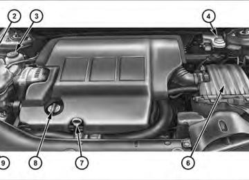
1 — Air Outlet 2 — Side Window Demister Outlet 3 — Instrument Cluster 4 — Ignition Switch 5 — Analog Clock
6 — Radio 7 — Passenger Airbag 8 — Glove Compartment 9 — Heated Seat Switch – If Equipped 10 — Hazard Switch
11 — Storage Compartment 12 — Climate Control 13 — Trunk Release Button
144 UNDERSTANDING YOUR INSTRUMENT PANEL INSTRUMENT CLUSTER
INSTRUMENT CLUSTER DESCRIPTIONS
1. Temperature Gauge The temperature gauge shows engine coolant tempera- ture. Any reading below the red area of the gauge shows that the engine cooling system is operating properly. The gauge pointer may show a higher than normal tempera- ture when driving in hot weather, up mountain grades, in heavy stop and go traffic, or when towing a trailer. If the pointer rises to the H (red) mark, the instrument cluster will sound a chime. Pull over and stop the vehicle. Idle the vehicle with the air conditioner turned off until the pointer drops back into the normal range. If the pointer remains on the H (red) mark, turn the engine off immediately and call for service. There are steps that you can take to slow down an impending overheat condition. If your air conditioning is on, turn it off. The air conditioning system adds heat to the engine cooling system and turning off the A/C
UNDERSTANDING YOUR INSTRUMENT PANEL 145
removes this heat. You can also turn the Temperature control to maximum heat, the Mode control to Floor and the Fan control to High. This allows the heater core to act as a supplement to the radiator and aids in removing heat from the engine cooling system. 2. Fuel Door ReminderThis is a reminder that the Fuel Filler Door is located on the left side of the vehicle.
3. Fuel Gauge When the ignition switch is in the ON position, the pointer will show the level of fuel remaining in the fuel tank. 4. Speedometer Indicates the vehicle speed in miles per hour (MPH) and kilometers per hour (km/h).
146 UNDERSTANDING YOUR INSTRUMENT PANEL 5. Low Fuel Light
When the fuel level drops to approximately 2.0 gal- lons (7.6 Liters), the fuel symbol will light and a single chime will sound.
NOTE: This light will remain on until a minimum of approximately 3.0 gallons of fuel is added. 6. Charging System Light
This light shows the status of the electrical charg- ing system. The light should come on briefly when the ignition is first turned on and remain on briefly as a bulb check. If the light stays on or comes on while driving, turn off some of the vehicle’s electrical devices, such as the Front Fog Lights or Rear Window Defroster. If the Charging System Light remains on, it means that the vehicle is experiencing a problem with the charging system. Obtain SERVICE IMMEDIATELY. See your local authorized dealer.
If jump starting is required, refer to “Jump Starting Procedures” in “What To Do In Emergencies”. 7. Airbag Warning Light
The light comes on and remains on for six to eight seconds as a bulb check when the ignition switch is first turned ON. If the light does not turn on during starting, stays on, or turns on while driving, have the system inspected by an autho- rized dealer. Refer to “Occupant Restraints” in “Things To Know Before Starting Your Vehicle” for further infor- mation. 8. Seat Belt Reminder Light
When the ignition switch is first turned ON, this light will come on for about six seconds. A chime will sound if you have not pulled the shoulder belt out of the retractor. This is a reminder to “buckle up”. If
you do not buckle up, the light will remain on. Refer to “Occupant Restraints” in “Things To Know Before Start- ing Your Vehicle” for further information. 9. Oil Pressure Warning Light
This light indicates low engine oil pressure. The light will come on and remain on when the ignition switch is turned from the OFF to the ON position, and the light will turn off after the engine is started. If the bulb does not come on during starting, have the system checked by an authorized dealer. If the light comes on and remains on while driving, stop the vehicle and shut off the engine. DO NOT OPERATE THE VEHICLE UNTIL THE CAUSE IS CORRECTED. The light does not show the quantity of oil in the engine. This can be determined using the procedure shown in “Maintaining Your Vehicle”.
UNDERSTANDING YOUR INSTRUMENT PANEL 147
10. Engine Temperature Warning Light
This light warns of an overheated engine condi- tion. If the engine is critically hot, a warning chime will sound 10 times. After the chime turns off, the engine will still be critically hot until the light goes out. 11. Brake Warning Light
This light monitors various brake functions, including brake fluid level and parking brake application. If the brake light turns on, it may indicate that the parking brake is applied, that the brake fluid level is low, or that there is a problem with the anti-lock brake system. The dual brake system provides a reserve braking capac- ity in the event of a failure to a portion of the hydraulic system. Failure of either half of the dual brake system is indicated by the Brake Warning Light which will turn on when the brake fluid level in the master cylinder has dropped below a specified level.
148 UNDERSTANDING YOUR INSTRUMENT PANEL The light will remain on until the cause is corrected. NOTE: The light may flash momentarily during sharp cornering maneuvers which change fluid level condi- tions. The vehicle should have service performed, and the brake fluid level checked. If brake failure is indicated, immediate repair is neces- sary.
WARNING!
Driving a vehicle with the brake light on is danger- ous. Part of the brake system may have failed. It will take longer to stop the vehicle. You could have an accident. Have the vehicle checked immediately.
Vehicles equipped with Anti-Lock brakes (ABS), are also equipped with Electronic Brake Force Distribution (EBD).
In the event of an EBD failure, the Brake Warning Light will turn on along with the ABS Light. Immediate repair to the ABS system is required. The operation of the Brake Warning Light can be checked by turning the ignition switch from the OFF position to the ON position. The light should illuminate for approxi- mately three seconds. The light should then turn off unless the parking brake is applied or a brake fault is detected. If the light does not illuminate, have the light inspected by an authorized dealer. The light also will turn on when the parking brake is applied with the ignition switch in the ON position. NOTE: This light shows only that the parking brake is applied. It does not show the degree of brake application.
12. Tachometer The silver area of the scale shows the permissible engine revolutions-per-minute (RPM x 1000) for each gear range. Before reaching the red area, ease up on the accelerator to prevent engine damage. 13. Shift Lever Indicator The Shift Lever Indicator is self-contained within the instrument cluster. It displays the gear position of the automatic transmission. NOTE: You must apply the brakes before shifting from PARK. 14. Odometer/Trip Odometer Display Area The odometer shows the total distance the vehicle has been driven. U.S. Federal regulations require that upon transfer of vehicle ownership, the seller certify to the purchaser the correct mileage that the vehicle has been
UNDERSTANDING YOUR INSTRUMENT PANEL 149
driven. If your odometer needs to be repaired or serviced, the repair technician should leave the odometer reading the same as it was before the repair or service. If s/he cannot do so, then the odometer must be set at zero, and a sticker must be placed in the door jamb stating what the mileage was before the repair or service. It is a good idea for you to make a record of the odometer reading before the repair/service, so that you can be sure that it is properly reset, or that the door jamb sticker is accurate if the odometer must be reset at zero. The two trip odometers show individual trip mileage. To switch from odometer to trip odometers, press and release the Trip Odometer button. To reset a trip odom- eter, display the desired trip odometer to be reset then push and hold the button until the display resets (ap- proximately 2 seconds). Refer to “Trip Odometer Button” for additional information.150 UNDERSTANDING YOUR INSTRUMENT PANEL Vehicle Odometer Messages When the appropriate conditions exist, the odometer will display the following messages:
door . . . . . . . . . . . . . . . . . . . . . . . . . . . . . Door Ajar deck. . . . . . . . . . . . . . . . . . . . . . . . . . . . . Trunk Ajar LoW TirE . . . . . . . . . . . . . . . . . . . . Low Tire Pressure CHAngE OIL . . . . . . . . . . . . . . . Oil Change Required gASCAP . . . . . . . . . . . . . . . . . . . . . . . Fuel Cap Fault HOTOIL . . . . . . . . . . . . Transmission Oil Temperature Exceeds Safe Threshold
If the instrument cluster is equipped with the NOTE: optional Electronic Vehicle Information Center (EVIC), then warnings such as ”Low Tire,” “Door Ajar” and “Trunk Ajar” will display in the EVIC. (Refer to “Elec- tronic Vehicle Information Center (EVIC)” for specific messages).
LoW TirE When the appropriate condition exists, the odometer display will toggle between LoW and TirE for three cycles. HOTOIL When this message is displayed there is a transmission over-temperature condition. When this condition occurs, the “HOTOIL” message will be displayed in the odom- eter along with a chime. NOTE: When this message is displayed, bring the vehicle to a stop and idle the engine in park until the message clears. Raising the idle of the engine slightly will help speed up the cooling. gASCAP If the vehicle diagnostic system detects a leak or change in the evaporative system, or the fuel filler cap is loose, improperly installed, or damaged, the words “gASCAP” will display in the odometer display area. If this occurs,
tighten the fuel filler cap properly and press the odom- eter reset button to turn off the “gASCAP” message. (Refer to “Onboard Diagnostic System — OBDII” in “Maintaining Your Vehicle” for further information). If the problem continues, the message will appear the next time the vehicle is started. See your authorized dealer service center as soon as possible. CHAngE OIL Your vehicle is equipped with an engine oil change indicator system. The “CHAngE OIL” message will flash in the instrument cluster odometer for approximately 12 seconds after a single chime has sounded to indicate the next scheduled oil change interval. The engine oil change indicator system is duty cycle based, which means the engine oil change interval may fluctuate dependent upon your personal driving style. Unless reset, this message will continue to display each time you turn the ignition switch to the “ON” position.
UNDERSTANDING YOUR INSTRUMENT PANEL 151
To turn off the message temporarily, press and release the Trip Odometer button on the instrument cluster. To reset the oil change indicator system (after performing the scheduled maintenance) perform the following proce- dure:1. Turn the ignition switch to the ON position (Do not start the engine). 2. Fully depress the accelerator pedal slowly 3 times within 10 seconds. 3. Turn the ignition switch to the LOCK position.
If the indicator message illuminates when you NOTE: start the vehicle, the oil change indicator system did not reset. If necessary repeat this procedure.
4. For vehicles equipped with the Electronic Vehicle Information Center (EVIC), refer to “Electronic Vehicle Information Center (EVIC)”.
152 UNDERSTANDING YOUR INSTRUMENT PANEL 15. Cruise Indicator — If Equipped
This indicator shows that the Electronic Speed Control System is ON.
16. Odometer/Trip Odometer Reset Button
Single Trip Odometer Press and release this button to change the display from odometer to trip odometer. The word “Trip” displays to show that the odometer is in Trip Mode. Press and release the button again to change the display back to the odometer. To reset the trip odometer, first set the display to Trip Mode. Then push and hold the button (approximately 2 seconds) until the display resets to 0 miles (km). The odometer must be in Trip Mode to reset the trip odom- eter.
Dual Trip Odometer — If Equipped Press and release this button to change the display from odometer to “Trip A.” Press and release it a second time to change the display to “Trip B.” Press and release it a third time to change the display back to the odometer. To reset the trip odometer, first display the trip mileage that you want to reset, “Trip A” or “Trip B.” Then push and hold the button (approximately 2 seconds) until the display resets to 0 miles (km). The odometer must be in Trip Mode to reset the trip odometer. 17. Electronic Throttle Control (ETC) Indicator Light
This light informs you of a problem with the Electronic Throttle Control (ETC) system. If a problem is detected, the light will come on while the engine is running. If the light remains lit with the engine running, your vehicle will usually be drivable and not need towing, however see your autho- rized dealer for service as soon as possible.
If the light is flashing when the engine is running you may experience power loss, an elevated/rough idle, and increased brake pedal effort, and your vehicle may require towing. Immediate service is required. The light will come on when the ignition switch is first turned on and remain on approximately 15 seconds as a bulb check. This is normal. If the light does not come on during starting, have the system checked by an autho- rized dealer. 18. Position Light Indicator — If Equipped
This indicator will illuminate when the park lights or headlights are turned on.
UNDERSTANDING YOUR INSTRUMENT PANEL 153
19. Electronic Stability Control (ESC) OFF Indicator Light — If Equipped
This light indicates the Electronic Stability Con- trol system (ESC) has been turned off by the driver.
20. Turn Signal Indicators
The arrows will flash in unison with the exterior turn signal, when using the turn signal lever.
21. Front Fog Light Indicator — If Equipped
This indicator will illuminate when the front fog lights are on.
22. Vehicle Security Light — If Equipped
This light will flash rapidly for approximately 16 seconds when the alarm system is arming. The light will begin to flash slowly indicating that the system is armed. The light will stop
flashing when the vehicle is disarmed.
154 UNDERSTANDING YOUR INSTRUMENT PANEL 23. Anti-Lock Brake (ABS) Light — If Equipped
This light monitors the ABS. This light will come on when the ignition key is turned to the ON position and may stay on for approxi- mately three seconds.
If the ABS light remains on or comes on during driving, it indicates that the Anti-Lock portion of the brake system is not functioning and that service is required, however, the conventional brake system will continue to operate normally provided that the BRAKE warning light is not on. If the ABS light is on, the brake system should be serviced as soon as possible to restore the benefit of Anti-Lock Brakes. The ABS warning light should be checked frequently to assure that it is operating properly. Turn the ignition key to the on position, but do not start the vehicle. The light
should come on. If the light does not come on, have the system inspected by an authorized dealer. 24. Electronic Stability Control (ESC) Activation/ Malfunction Indicator Light — If Equipped
The “ESC Activation/Malfunction Indicator Light” in the instrument cluster will come on when the ignition switch is turned to the ON position. It should go out with the engine running. If the “ESC Activation/Malfunction Indicator Light” comes on continuously with the engine running, a malfunction has been detected in the ESC system. If this light remains on after several ignition cycles, and the vehicle has been driven several miles (kilometers) at speeds greater than 30 mph (48 km/h), see your autho- rized dealer as soon as possible to have the problem diagnosed and corrected. NOTE: • The “ESC Off
Indicator Light” and the “ESC
will be ON even if it was turned off previously.
Activation/Malfunction Indicator Light” come on mo- mentarily each time the ignition switch is turned ON. • Each time the ignition is turned ON, the ESC system • The ESC system will make buzzing or clicking sounds when it is active. This is normal; the sounds will stop when ESC becomes inactive following the maneuver that caused the ESC activation.
25. Tire Pressure Monitoring Telltale Light
Each tire, including the spare (if provided), should be checked monthly, when cold and inflated to the inflation pressure recommended by the vehicle manufacturer on the vehicle placard or tire inflation pressure label. (If your vehicle has tires of a different size than the size indicated on the vehicle placard or tire inflation pressure label, you should determine the proper tire inflation pressure for those tires.)
UNDERSTANDING YOUR INSTRUMENT PANEL 155
As an added safety feature, your vehicle has been equipped with a Tire Pressure Monitoring System (TPMS) that illuminates a low tire pressure telltale when one or more of your tires is significantly under-inflated. Accordingly, when the low tire pressure telltale illumi- nates, you should stop and check your tires as soon as possible, and inflate them to the proper pressure. Driving on a significantly under-inflated tire causes the tire to overheat and can lead to tire failure. Under-inflation also reduces fuel efficiency and tire tread life, and may affect the vehicle’s handling and stopping ability. Please note that the TPMS is not a substitute for proper tire maintenance, and it is the driver’s responsibility to maintain correct tire pressure, even if under-inflation has not reached the level to trigger illumination of the TPMS low tire pressure telltale.156 UNDERSTANDING YOUR INSTRUMENT PANEL Your vehicle has also been equipped with a TPMS malfunction indicator to indicate when the system is not operating properly. The TPMS malfunction indicator is combined with the low tire pressure telltale. When the system detects a malfunction, the telltale will flash for approximately one minute and then remain continuously illuminated. This sequence will continue upon subse- quent vehicle start-ups as long as the malfunction exists. When the malfunction indicator is illuminated, the sys- tem may not be able to detect or signal low tire pressure as intended. TPMS malfunctions may occur for a variety of reasons, including the installation of replacement or alternate tires or wheels on the vehicle that prevent the TPMS from functioning properly. Always check the TPMS malfunction telltale after replacing one or more tires or wheels on your vehicle, to ensure that the replacement or alternate tires and wheels allow the TPMS to continue to function properly.
CAUTION!
The TPMS has been optimized for the original equipment tires and wheels. TPMS pressures and warning have been established for the tire size equipped on your vehicle. Undesirable system opera- tion or sensor damage may result when using re- placement equipment that is not of the same size, type, and/or style. Aftermarket wheels can cause sensor damage. Do not use tire sealant from a can, or balance beads if your vehicle is equipped with a TPMS, as damage to the sensors may result.
26. Malfunction Indicator Light (MIL)
The Malfunction Indicator Light (MIL) is part of an onboard diagnostic system called OBD that monitors emissions, engine, and automatic trans- mission control systems. The light will illuminate when the key is in the ON position before engine start. If the
bulb does not come on when turning the key from LOCK to ON, have the condition checked promptly. Certain conditions such as a loose or missing gas cap, poor fuel quality, etc., may illuminate the light after engine start. The vehicle should be serviced if the light stays on through several of your typical driving cycles. In most situations, the vehicle will drive normally and will not require towing.
CAUTION!
Prolonged driving with the MIL on could cause damage to the engine control system. It also could affect fuel economy and drivability. If the MIL is flashing, severe catalytic converter damage and power loss will soon occur. Immediate service is required.
UNDERSTANDING YOUR INSTRUMENT PANEL 157
WARNING!
A malfunctioning catalytic converter, as referenced above, can reach higher temperatures than in normal operating conditions. This can cause a fire if you drive slowly or park over flammable substances such as dry plants or wood or cardboard, etc. This could result in death or serious injury to the driver, occu- pants or others.
27. Transmission Temperature Warning Light — If Equipped
This light indicates that the transmission fluid temperature is running hot. This may occur with severe usage, such as trailer towing. If this light turns on, safely pull over and stop the vehicle. Then, shift the transmission into NEUTRAL and run the engine at idle or faster until the light turns off.
158 UNDERSTANDING YOUR INSTRUMENT PANEL
CAUTION!
Continuous driving with the Transmission Tempera- ture Warning Light illuminated will eventually cause severe transmission damage or transmission failure.
WARNING!
Continued operation with the Transmission Tem- perature Warning Light illuminated could cause the fluid to boil over, come in contact with hot engine or exhaust components causing a fire that may result in personal injury.
29. Electronic Vehicle Information Center (EVIC) Display — If Equipped This display shows the EVIC messages when the appro- priate conditions exist. Refer to “Electronic Vehicle Infor- mation Center (EVIC)” for further information.
ELECTRONIC VEHICLE INFORMATION CENTER (EVIC) – IF EQUIPPED The Electronic Vehicle Information Center (EVIC) fea- tures a driver-interactive display that is located in the instrument cluster.
28. High Beam Indicator
This light indicates that the headlights are on high beam. Pull the turn signal lever toward the steer-
ing wheel to switch the headlights to low beam.
SW)
UNDERSTANDING YOUR INSTRUMENT PANEL 159
• Compass heading display (N, S, E, W, NE, NW, SE, • Outside temperature display (°F or °C) • Trip computer functions • Audio mode displays – 12 preset Radio Stations or CD • Tire Pressure Monitor System (TPMS) displays (if
Title and Track number when playing
equipped)
Electronic Vehicle Information Center (EVIC)
The EVIC consists of the following: • System status • Vehicle information warning message displays • Personal Settings (Customer-Programmable Features)
The system allows the driver to select information by pressing the following buttons on the instrument panel switch bank located below the climate controls:
Press and release the MENU button to advance the display to Trip Functions or Personal set- tings or to return to the default System status display.
MENU Button
160 UNDERSTANDING YOUR INSTRUMENT PANEL
Press and release the STEP button to advance the display through the various Trip Functions or Personal settings.
STEP Button
COMPASS
Button
Press and release the COMPASS button to display the compass heading and the out- side temperature.
Press and release the RESET button to accept a selection. The RESET button also resets various Trip Functions.
RESET Button
after one mile traveled)
Electronic Vehicle Information Center (EVIC) Displays When the appropriate conditions exist, the EVIC displays the following messages. • Turn Signal On (with a continuous warning chime • Left Front Turn Signal Light Out (with a single chime) • Left Rear Turn Signal Light Out (with a single chime) • Right Front Turn Signal Light Out (with a single • Right Rear Turn Signal Light Out (with a single chime) • RKE (Remote Keyless Entry) Battery Low (with a • Personal Settings Not Available – Vehicle Not In PARK • Personal Settings Not Available – Vehicle in Motion
single chime)
chime)
motion)
• Door(s) Ajar (with a single chime if vehicle is in • Trunk Ajar (with a single chime) • Headlights On • Key In Ignition • Oil Change Required (with a single chime) • ECO (Fuel Saver Indicator) — If Equipped Oil Change Required — If Equipped Your vehicle is equipped with an engine oil change indicator system. The Oil Change Required message will flash in the EVIC display for approximately five seconds after a single chime has sounded to indicate the next scheduled oil change interval. The engine oil change indicator system is duty cycle based, which means the engine oil change interval may fluctuate dependent upon your personal driving style.
UNDERSTANDING YOUR INSTRUMENT PANEL 161
Unless reset, this message will continue to display each time you turn the ignition switch to the ON/RUN position. To turn off the message temporarily, press and release the MENU button. To reset the oil change indica- tor system (after performing the scheduled maintenance) perform the following procedure: 1. Turn the ignition switch to the ON position (Do not start the engine). 2. Fully depress the accelerator pedal slowly three times within 10 seconds. 3. Turn the ignition switch to the LOCK position. If the indicator message illuminates when you NOTE: start the vehicle, the oil change indicator system did not reset. If necessary repeat this procedure.162 UNDERSTANDING YOUR INSTRUMENT PANEL Trip Functions Press and release the MENU button until one of the following Trip Functions displays in the EVIC: • ECO (Fuel Saver Indicator) — If Equipped • Average Fuel Economy • Distance To Empty • Elapsed Time • Display Units of Measure in Press and release the STEP button to advance the display through the Trip Functions.
The Trip Functions mode displays the following informa- tion: • ECO (Fuel Saver Indicator) — If Equipped The ECO indicator will illuminate in the EVIC display. This ECO message will appear when you are driving in a fuel efficient manner and can be used to modify driving habits in order to increase fuel economy. • Average Fuel Economy Shows the average fuel economy since the last reset. When the fuel economy is reset, the display will read, RESET or show dashes for two seconds. Then, the history information will be erased, and the averaging will con- tinue from the last fuel average reading before the reset. • Distance To Empty (DTE) Shows the estimated distance that can be traveled with the fuel remaining in the tank. This estimated distance is determined by a weighted average of the instantaneous
and average fuel economy, according to the current fuel tank level. DTE cannot be reset through the RESET button. NOTE: Significant changes in driving style or vehicle loading will greatly affect the actual drivable distance of the vehicle, regardless of the DTE display value. When the DTE value is less than 30 miles (48 km) estimated driving distance, the DTE display will change to a text display of ⬙LOW FUEL”. This display will continue until the vehicle runs out of fuel. Adding a significant amount of fuel to the vehicle will turn off the LOW FUEL text and a new DTE value will display. • Elapsed Time Shows the total elapsed time of travel since the last reset. Elapsed time will increment when the ignition switch is in the ON or START position.
UNDERSTANDING YOUR INSTRUMENT PANEL 163
• Display Units In: To make your selection, press and release the RESET button until ENGLISH or METRIC appears. To Reset The Display Reset will only occur if a resettable function is currently displayed. Press and hold the RESET button once to clear the function currently displayed. To reset all resettable functions, press and release the RESET button a second time within three seconds of resetting the currently displayed function (Reset ALL will display during this three-second window). Compass Display
The compass heading indicates the direction the vehicle is facing. Press and release the compass button to display one of eight compass heading and the outside tempera- ture.
COMPASS
Button
164 UNDERSTANDING YOUR INSTRUMENT PANEL NOTE: The system will display the last known outside temperature when starting the vehicle and may need to be driven several minutes before the updated tempera- ture is displayed. Engine temperature can also affect the displayed temperature, therefore temperature readings are not updated when the vehicle is not moving. Automatic Compass Calibration This compass is self-calibrating, which eliminates the need to calibrate the compass manually. When the ve- hicle is new, the compass may appear erratic and the EVIC will flash the “CAL” indicator until the compass is calibrated. You may calibrate the compass by completing one or more 360–degree turns (in an area free from large metal or metallic objects) until the CAL indicator in the EVIC turns off. The compass will now function normally. NOTE: A good calibration requires a level surface and an environment free from large metallic objects such as build- ings, bridges, underground cables, railroad tracks, etc.
Manual Compass Calibration If the compass appears erratic or inaccurate, and the variance has been properly set, you may wish to manu- ally recalibrate the compass. To manually calibrate the compass: 1. Start the engine. Leave the shift lever in PARK in order to enter the EVIC Programming Menus. 2. Press and release the MENU button until “Personal Settings” displays in the EVIC. 3. Press and release the STEP button until “Calibrate Compass Yes” displays in the EVIC. 4. Press and release the RESET button and the “CAL” indicator will quit flashing. 5. Drive the vehicle slowly (under 5 mph / 8 km/h), completing one or more circles (in an area free from large metal or metallic objects) until the “CAL” indicator turns off. The compass will now function normally.
Compass Variance Compass Variance is the difference between Magnetic North and Geographic North. To compensate for the differences, the variance should be set for the zone where the vehicle is driven, per the zone map. Once properly set, the compass will automatically compensate for the differences and provide the most accurate compass head- ing. NOTE: Magnetic and battery powered devices, (such as cell phones, iPod’s, radar detectors, PDA’s and laptops) should be kept away from the top of the instrument panel. This is where the compass module is located and such devices may interfere and cause false compass readings.
UNDERSTANDING YOUR INSTRUMENT PANEL 165
Compass Variance Map
1. Turn the ignition switch to the ON position. Leave the shift lever in PARK. 2. Press and release the MENU button until “Personal Settings” displays in the EVIC.
166 UNDERSTANDING YOUR INSTRUMENT PANEL 3. Press and release the STEP button until “Compass Variance” and the current Variance Value displays in the EVIC. 4. Press and release the RESET button to increment the Variance Value by one, (one button press per update), until the proper variance zone is selected according to the map. NOTE: The Variance Values will wrap around from 15
back to 1. The Default Variance is Zone 8. 5. Press and release the STEP button to exit. Press the STEP button if you wish to calibrate the compass manu- ally (Refer to “Manual Compass Calibration”). Personal Settings (Customer-Programmable Features) Personal settings allows the driver to set and recall features when the automatic transaxle is in PARK.Press and release the MENU button until “Personal Settings” displays in the EVIC. Press and release the STEP button to display the follow- ing programmable features: Language When in this display you may select different languages for all display nomenclature, including the trip functions. Pressing the RESET button while in this display selects English, Spanish, French, German, Italian, or Dutch de- pending on availability. As you continue, the displayed information will be shown in the selected language. Auto Unlock on Exit When ON is selected and the transaxle is in the PARK or NEUTRAL position, all doors will unlock when the driver’s door is opened. To make your selection, press and hold the RESET button until ON or OFF appears.
Remote Key Unlock When “Driver Door 1st Press” is selected, only the driver’s door will unlock on the first press of the Remote Keyless Entry (RKE) transmitter UNLOCK button. When Driver Door 1st Press is selected, you must press of the RKE transmitter UNLOCK button twice to unlock the passenger’s doors. When “All Doors 1st Press” is se- lected, all of the doors will unlock on the first press of the RKE transmitter UNLOCK button. To make your selec- tion, press and release the RESET button until “Driver Door 1st Press” or “All Doors 1st Press” appears. Sound Horn with Lock When ON is selected, a short horn sound will occur when the RKE transmitter LOCK button is pressed. This feature may be selected with or without the Flash Lights with Lock feature. To make your selection, press and release the RESET button until ON or OFF appears.
UNDERSTANDING YOUR INSTRUMENT PANEL 167
Flash Lights with Lock When ON is selected, the front and rear turn signals will flash when the doors are locked or unlocked with the RKE transmitter. This feature may be selected with or without the Sound Horn on lock feature selected. To make your selection, press and release the RESET button until ON or OFF appears. Headlights Off Delay When this feature is selected, the driver can choose to have the headlights remain on for 0, 30, 60, or 90 seconds when exiting the vehicle. To make your selection, press and hold the RESET button until 0, 30, 60, or 90 seconds appears. Headlights With Wipers (Available with Auto Headlights Only) When ON is selected, and the headlight switch is in the AUTO position, the headlights will turn on approxi- mately 10 seconds after the wipers are turned on. The
168 UNDERSTANDING YOUR INSTRUMENT PANEL headlights will also turn off when the wipers are turned off if they were turned on by this feature. To make your selection, press and hold the RESET button until ON or OFF appears. NOTE: Turning the headlights on during the daytime causes the instrument panel lights to dim. To increase the brightness, refer to “Lights” in “Understanding The Features Of Your Vehicle”. Key-Off Power Delay When this feature is selected, the power window switches, radio, Uconnect™ Phone (if equipped), and power outlets will remain active for up to 10 minutes after the ignition switch is turned to the LOCK position. Opening a vehicle door will cancel this feature. To make your selection, press and hold the RESET button until Off, 45 sec., 5 min., or 10 min. appears.
Illuminated Approach When this feature is selected, the headlights will activate and remain on for up to 90 seconds when the doors are unlocked with the remote keyless entry transmitter. To make your selection, press and hold the RESET button until “OFF,” “30 sec,” “60 sec,” or “90 sec” appears. Display ECO — If Equipped The “ECO” message is located in the EVIC, this message can be turned on or off. To make your selection, press and release the FUNCTION SELECT button until “ON” or “OFF” appears. Display Units In The EVIC and odometer can be changed between English and Metric units of measure. To make your selection, press and release the RESET button until “ENGLISH” or “METRIC” appears.
SETTING THE ANALOG CLOCK
UNDERSTANDING YOUR INSTRUMENT PANEL 169
MEDIA CENTER 230 (REQ) — AM/FM STEREO RADIO AND 6–DISC CD/DVD CHANGER (MP3/WMA AUX JACK)
NOTE: The radio sales code is located on the lower right side of the radio faceplate.
To set the analog clock, located at the top center of the instrument panel, press and hold the button in until the setting is correct. The clock will adjust slowly at first and then quicker the longer the button is held.
Media Center 230 (REQ)
170 UNDERSTANDING YOUR INSTRUMENT PANEL Operating Instructions - Radio Mode
NOTE: The ignition switch must be in the ON or ACC position to operate the radio. Power Switch/Volume Control (Rotary) Push the ON/VOLUME control knob to turn on the radio. Press the ON/VOLUME control knob a second time to turn off the radio. Electronic Volume Control The electronic volume control turns continuously (360
degrees) in either direction without stopping. Turning the ON/VOLUME control knob to the right increases the volume and to the left decreases it. When the audio system is turned ON, the sound will be set at the same volume level as last played. SEEK Buttons Press and release the SEEK buttons to search for the next listenable station in AM/FM mode. Press the right switchto seek up and the left switch to seek down. The radio will remain tuned to the new station until you make another selection. Holding either button will bypass stations without stopping until you release it. SCAN Button Pressing the SCAN button causes the tuner to search for the next listenable station in AM, FM or Satellite (if equipped) frequencies, pausing for five seconds at each listenable station before continuing to the next. To stop the search, press the SCAN button a second time. Voice Command Button Uconnect™ Phone — If Equipped Press this button to operate the Uconnect™ Phone feature (if equipped). Refer to “Voice Command in the Uconnect™ User Manual located on the DVD for further details.
If your vehicle is not equipped with or this feature is not available on your vehicle, a “Not Equipped With Uconnect Phone” message will display on the radio screen. Phone Button Uconnect™ Phone — If Equipped Press this button to operate the Uconnect™ Phone feature (if equipped). Refer to “Uconnect™ Phone” in the Uconnect™ User Manual located on the DVD for further details. If your vehicle is not equipped with or this feature is not available on your vehicle, a “Not Equipped With Uconnect Phone” message will display on the radio screen. TIME Button Press the TIME button to alternate locations of the time and frequency display.
UNDERSTANDING YOUR INSTRUMENT PANEL 171
Clock Setting Procedure 1. Press and hold the TIME button until the hours blink. 2. Adjust the hours by turning the right side TUNE/ SCROLL control knob. 3. After adjusting the hours, press the right side TUNE/ SCROLL control knob to set the minutes. The minutes will begin to blink. 4. Adjust the minutes using the right side TUNE/ SCROLL control knob. Press the TUNE/SCROLL control knob to save the time change. 5. To exit, press any button/knob or wait five seconds. The clock can also be set by pressing the SETUP button and selecting the “SET HOME CLOCK” entry. Once in this display follow the above procedure, starting at step 2.
172 UNDERSTANDING YOUR INSTRUMENT PANEL INFO Button Press the INFO button for an RDS station (one with call letters displayed). The radio will return a Radio Text message broadcast from an FM station (FM mode only). RW/FF Pressing the RW (Rewind) or FF (Fast Forward) buttons causes the tuner to search for the next frequency in the direction of the arrows. This feature operates in AM, FM or Satellite (if equipped) frequencies. TUNE Control Turn the rotary TUNE/SCROLL control knob clockwise to increase or counterclockwise to decrease the frequency. Setting the Tone, Balance, and Fade Push the rotary TUNE/SCROLL control knob and BASS will display. Turn the TUNE/SCROLL control knob to the right or left to increase or decrease the bass tones.
Push the rotary TUNE/SCROLL control knob a second time and MID will display. Turn the TUNE/SCROLL control knob to the right or left to increase or decrease the mid-range tones. Push the rotary TUNE/SCROLL control knob a third time and TREBLE will display. Turn the TUNE/SCROLL control knob to the right or left to increase or decrease the treble tones. Push the rotary TUNE/SCROLL control knob a fourth time and BALANCE will display. Turn the TUNE/ SCROLL control knob to the right or left to adjust the sound level from the right or left side speakers. Push the rotary TUNE/SCROLL control knob a fifth time and FADE will display. Turn the TUNE/SCROLL control knob to the left or right to adjust the sound level between the front and rear speakers.
UNDERSTANDING YOUR INSTRUMENT PANEL 173
Push the rotary TUNE/SCROLL control knob again to exit setting tone, balance, and fade. MUSIC TYPE Button Pressing this button once will turn on the Music Type mode for five seconds. Pressing the MUSIC TYPE button or turning the TUNE/SCROLL control knob within five seconds will allow the program format type to be se- lected. Many radio stations do not currently broadcast Music Type information. Toggle the MUSIC TYPE button to select the following format types:
Program Type
No program type or
undefined Adult Hits Classical
16-Digit Character
Display
None
Adlt Hit Classicl
Program Type
Classic Rock
College Country
Foreign Language
Information
Jazz News
Nostalgia
Oldies
Personality
Public
Rhythm and Blues Religious Music Religious Talk
Rock
16-Digit Character
Display Cls Rock College Country Language
Inform Jazz News
Nostalga Oldies Persnlty Public R & B
Rel Musc Rel Talk
Rock
174 UNDERSTANDING YOUR INSTRUMENT PANEL
Program Type
Soft
Soft Rock
Soft Rhythm and Blues
Sports Talk Top 40
Weather16-Digit Character
Display
Soft
Soft Rck Soft R & B
Sports Talk Top 40
WeatherBy pressing the SEEK button when the Music Type icon is displayed, the radio will be tuned to the next frequency station with the same selected Music Type name. The Music Type function only operates when in the FM mode. If a preset button is activated while in the Music Type (Program Type) mode, the Music Type mode will be exited and the radio will tune to the preset station.
SETUP Button Pressing the SETUP button allows you to select between the following items: NOTE: Turn the TUNE/SCROLL control knob to scroll through the entries. Push the AUDIO/SELECT button to select an entry and make changes. • DVD Enter - When the disc is in DVD Menu mode, selecting DVD Enter will allow you to play the current highlighted selection. Use the remote control to scroll up and down the menu (if equipped). • DISC Play/Pause - You can toggle between playing the DVD and pausing the DVD by pushing the SELECT button (if equipped).
• DVD Play Options - Selecting the DVD Play Options will display the following: • Subtitle – Repeatedly pressing SELECT will switch subtitles to different subtitle languages that are available on the disc (if equipped). • Audio Stream – Repeatedly pressing SELECT will switch to different audio languages (if supported on the disc) (if equipped). • Angle – Repeatedly pressing SELECT will change the viewing angle if supported by the DVD disc (if equipped).
NOTE: • The available selections for each of the above entries • These selections can only be made while playing a
varies depending upon the disc.
DVD.
equipped).
UNDERSTANDING YOUR INSTRUMENT PANEL 175
OFF (if equipped).
• VES™ Power - Allows you to turn VES™ ON and • VES™ Lock - Locks out rear VES™ remote controls (if • VES™ CH1/CH2 - Allows the user to change the mode of either the IR1 or IR2 wireless headphones by pressing the AUDIO/SELECT button (if equipped). • Set Home Clock - Pressing the SELECT button allows you to set the clock. Turn the TUNE/SCROLL control knob to adjust the hours and then press and turn the TUNE/SCROLL control knob to adjust the minutes. Press the TUNE/SCROLL control knob again to save changes. • Player Defaults - Selecting this item will allow the user to scroll through the following items and set defaults according to customer preference.
176 UNDERSTANDING YOUR INSTRUMENT PANEL Menu Language — If Equipped Selecting this item will allow the user to choose the default startup DVD menu language (effective only if language supported by disc). If you want to select a language not listed, then scroll down and select ⬙other.⬙ Enter the four-digit country code using the TUNE/ SCROLL control knob to scroll up and down to select the number and then push to select. Audio Language — If Equipped Selecting this item allows you to choose a default audio language (effective only if the language is supported by the disc). You can select a language not listed by scrolling down and selecting ⬙other.⬙ Enter the country code using the TUNE/SCROLL control knob to scroll up and down to select the number and then push to select. Subtitle Language — If Equipped Selecting this item allows you to choose a default subtitle language (effective only if the language is supported by
the disc). You can select a language not listed by scrolling down and selecting ⬙other.⬙ Enter the country code using the TUNE/SCROLL control knob to scroll up and down to select the number and then push to select. Subtitles — If Equipped Selecting this item allows you to choose between subtitle Off or On. Audio DRC — If Equipped Selecting this item allows you to limit maximum audio dynamic range. The default is set to ⬙High,⬙ and under this setting, dialogues will play at 11 db higher than if the setting is ⬙Normal.⬙ Aspect Ratio — If Equipped Selecting this item allows you to choose between wide screen, pan scan, and letter box.
AutoPlay — If Equipped When this is set to On and a DVD video is inserted, it will bypass the DVD menu screen and automatically play the movie. In some rare cases, the DVD player may not auto-play the main title. In such cases, use the MENU button on the remote control to select desired title to play. NOTE: The user will have to set these defaults before loading a disc. If changes are made to these settings after a disc is loaded, changes will not be effective. Also, the defaults are effective only if the disc supports the customer-preferred settings. AM and FM Buttons Press the buttons to select AM or FM mode. SET Button — To Set the Pushbutton Memory When you are receiving a station that you wish to commit to pushbutton memory, press the SET button. The symbol SET 1 will now show in the display window. Select the button (1-6) you wish to lock onto this station
UNDERSTANDING YOUR INSTRUMENT PANEL 177
and press and release that button. If a button is not selected within five seconds after pressing the SET but- ton, the station will continue to play but will not be stored into pushbutton memory. You may add a second station to each pushbutton by repeating the above procedure with this exception: Press the SET button twice and SET 2 will show in the display window. Each button can be set for SET 1 and SET 2 in both AM and FM. This allows a total of 12 AM, 12 FM, and 12 Satellite (if equipped) stations to be stored into pushbutton memory. The stations stored in SET 2
memory can be selected by pressing the pushbutton twice. Every time a preset button is used, a corresponding button number will display.178 UNDERSTANDING YOUR INSTRUMENT PANEL Buttons 1 - 6
These buttons tune the radio to the stations that you commit to pushbutton memory {12 AM, 12 FM, and 12
Satellite (if equipped) stations}. DISC Button Pressing the DISC button will allow you to switch from AM/FM modes to Disc modes. Operation Instructions - (DISC MODE for CD and MP3/WMA Audio Play, DVD-VIDEO) The radio DVD player and many DVD discs are coded by geographic region. These region codes must match in order for the disc to play. If the region code for the DVD disc does not match the region code for the radio DVD player, it will not play the disc. Customers may take their vehicle to an authorized dealer to change the region code of the player a maximum of five times.CAUTION!
The radio may shut down during extremely hot conditions. When this occurs, the radio will indicate “Disc Hot” and shut off until a safe temperature is reached. This shutdown is necessary to protect the optics of the DVD player and other radio internal components.
NOTE: The ignition switch must be in the ON or ACC position to operate the radio. LOAD Button — Loading Compact Disc(s) Press the LOAD button and the pushbutton with the corresponding number (1-6) where the CD is being loaded. The radio will display PLEASE WAIT and prompt when to INSERT DISC. After the radio displays ⬙INSERT DISC,⬙ insert the CD into the player.
Radio display will show ⬙LOADING DISC⬙ when the disc is loading and “READING DISC” when the radio is reading the disc.
CAUTION!
This CD player will accept 4–3/4 in (12 cm) discs only. The use of other sized discs may damage the CD player mechanism.
Eject Button — Ejecting Compact Disc(s)
Press the EJECT button and the pushbutton with the corresponding number (1-6) where the CD was loaded and the disc will unload and move to the entrance for easy removal. Radio display will show ⬙EJECTING DISC⬙ when the disc is being ejected and prompt the user to remove the disc. Press and hold the EJECT button for five seconds and all CDs will be ejected from the radio.
UNDERSTANDING YOUR INSTRUMENT PANEL 179
The disc can be ejected with the radio and ignition OFF. SEEK Button (CD MODE) Press the right SEEK button for the next selection on the CD. Press the left SEEK button to return to the beginning of the current selection, or return to the beginning of the previous selection if the CD is within the first second of the current selection. Pressing and holding the SEEK button will allow you to scroll through the tracks faster in CD and MP3/MWA modes. SCAN Button (CD MODE) Press the SCAN button to scan through each track on the CD currently playing. TIME Button (CD MODE) Press this button to change the display from a large CD playing time display to a small CD playing time display.180 UNDERSTANDING YOUR INSTRUMENT PANEL RW/FF (CD MODE) Press and hold FF (Fast Forward) and the CD player will begin to fast forward until FF is released, or RW or another CD button is pressed. The RW (Rewind) button works in a similar manner. AM or FM Button (CD MODE) Switches the radio into the AM or FM radio mode. Notes On Playing MP3/WMA Files The radio can play MP3/WMA files; however, acceptable MP3/WMA file recording media and formats are limited. When writing MP3/WMA files, pay attention to the following restrictions. Supported Media (Disc Types) The MP3/WMA file recording media supported by the radio are CDDA, CD-R, CD-RW, MP3,WMA, DVD Video, DVD-R, DVD-RW, DVD+R, DVD+RW, and CDDA+MP3.
Supported Medium Formats (File Systems) The medium formats supported by the radio are ISO 9660
Level 1 and Level 2 and includes the Joliet extension. When reading discs recorded using formats other than ISO 9660 Level 1 and Level 2, the radio may fail to read files properly and may be unable to play the file nor- mally. UDF and Apple HFS formats are not supported. The radio uses the following limits for file systems: • Maximum number of directory levels: 8
• Maximum number of files: 255
• Maximum number of folders: 100
• Maximum number of characters in file/folder names: • Level 1: 12 (including a separator ⬙.⬙ and a three- • Level 2: 31 (including a separator ⬙.⬙ and a three-character extension)
character extension)
Multisession disc formats are supported by the radio. Multisession discs may contain combinations of normal CD audio tracks and computer files (including MP3/ WMA files). Discs created with an option such as ⬙keep disc open after writing⬙ are most likely multisession discs. The use of multisession for CD audio or MP3/ WMA playback may result in longer disc loading times. If a disc contains multi-formats, such as CD audio and MP3/WMA tracks, the radio will only play the MP3/ WMA tracks on that disc. Supported MP3/WMA File Formats The radio will recognize only files with the *.MP3/WMA extension as MP3/WMA files. Non-MP3/WMA files named with the *.MP3/WMA extension may cause play- back problems. The radio is designed to recognize the file as an invalid MP3/WMA and will not play the file. When using the MP3/WMA encoder to compress audio data to an MP3/WMA file, the bit rate and sampling
UNDERSTANDING YOUR INSTRUMENT PANEL 181
frequencies in the following table are supported. In addition, variable bit rates (VBR) are also supported. The majority of MP3/WMA files use a 44.1 kHz sampling rate and a 192, 160, 128, 96 or VBR bit rates.MPEG
Specification
MPEG-1 Audio
Layer 3
MPEG-2 Audio
Layer 3
WMA
Specification
WMA
Sampling
Frequency (kHz) Bit Rate (kbps) 320, 256, 224, 192, 160, 128, 112, 96, 80, 64,
48, 44.1, 32
56, 48
24, 22.05, 16
160, 128, 144, 112, 96, 80, 64,
56, 48
Sampling
Frequency (kHz) Bit Rate (kbps) 48, 64, 96, 128, 160, 192 VBR
44.1 and 48
182 UNDERSTANDING YOUR INSTRUMENT PANEL ID3 Tag information for artist, song title, and album title are supported for ID3 version 1 tags. ID3 version 2 is not supported by the radios. Playlist files are not supported. MP3 Pro files are not supported. Playback of MP3/WMA Files When a medium containing MP3/WMA data is loaded, the radio checks all files on the medium. If the medium contains a lot of folders or files, the radio will take more time to start playing the MP3/WMA files. Loading times for playback of MP3/WMA files may be affected by the following: • Media - CD-RW media may take longer to load than • Medium formats - Multisession discs may take longer
CD-R media
to load than non-multisession discs
• Number of files and folders - Loading times will