- 2009 Chrysler Sebring Convertible Owners Manuals
- Chrysler Sebring Convertible Owners Manuals
- 2004 Chrysler Sebring Convertible Owners Manuals
- Chrysler Sebring Convertible Owners Manuals
- 2006 Chrysler Sebring Convertible Owners Manuals
- Chrysler Sebring Convertible Owners Manuals
- 2005 Chrysler Sebring Convertible Owners Manuals
- Chrysler Sebring Convertible Owners Manuals
- 2010 Chrysler Sebring Convertible Owners Manuals
- Chrysler Sebring Convertible Owners Manuals
- Download PDF Manual
-
The mode control allows you to choose from several patterns of air distribution.
UNDERSTANDING YOUR INSTRUMENT PANEL 123
† Recirculation — Air Conditioning
Recirculated interior air is cooled and sent through the instrument panel vents. Upon initial start up of the vehicle in very hot or humid weather, open windows and put in outside air modes to flush hot/humid air out. Then turn on the Recirculation mode to cool the vehicle interior rapidly. The Recirculation mode can also be used to temporarily block out any outside odors, smoke, or dust.
NOTE: Continuous use of the Recirculation mode may make the inside air stuffy and under mild, humid condi- tions cause windows to fog. Use of this mode for longer than 15 minutes is not recommended. † Panel — Air Conditioning
Outside air flows through the air condition- ing system and then through the outlets located in the instrument panel.
† Bi-Level — Air Conditioning
Outside air flows through the air conditioning system and then through the outlets located in
both the instrument panel and floor outlets.
124 UNDERSTANDING YOUR INSTRUMENT PANEL
† Panel
† Bi-Level
Air is directed through the outlets in the instru- ment panel. These outlets can be adjusted to direct air flow.
Air is directed through the instrument panel and floor outlets.
NOTE: There is a difference in temperature between the upper and lower outlets for added comfort. The warmer air goes to the floor outlets. This feature gives improved comfort during sunny but cool conditions. † Floor
Air is directed through the floor outlets with a lesser amount through the defrost and side window demist outlets.
† Mix
Air is directed through the floor, defrost and side window demist outlets. This setting works best in cold or snowy conditions that require extra heat at the windshield. This setting is good for maintaining comfort while reducing moisture on the windshield.
† Defrost
Air is directed through the windshield and side window demist outlets. Use this mode with maximum fan and temperature settings for best windshield and side window defrosting.
NOTE: The air conditioning compressor operates in both Mix and Defrost modes even if the Air Conditioning is not selected. This dehumidifies the air to help dry the windshield. Rear Seat Outlets These outlets are located under the front seats and direct warm air to the rear seat passengers. Air is directed through these outlets when you select either the Floor, Bi-Level, or Mix modes. Rear Window Defroster
The Rear Window Defroster button is located to the right of the Mode Control. Press this button once to turn on the Rear Window Defrost and a second time to turn them off. A light above the button shows that the defroster is on.
NOTE: The defroster turns off automatically after 15
minutes of operation. Each later activation will allow 10
minutes of operation. Side Window Demisters A side window demister outlet is at each end of the instrument panel. These non-adjustable outlets direct air toward the side windows when the system is in either the FLOOR, MIX, or DEFROST modes. A small amount of air is directed to the side window demisters in BI-LEVEL mode as well. The air is directed at the area of the windows through which you view the outside mirrors. Windshield and Side Window FoggingInterior fogging on the windshield can be quickly removed by using the defrost position on the mode
control.
Your side windows may fog on the inside in mild rainy or humid weather. To clear the windows, select the Panel-Air Conditioning mode on the Mode Control. Point the panel outlets toward the side windows.
UNDERSTANDING YOUR INSTRUMENT PANEL 125
NOTE: Do not use the recirculation mode as it will not clear windows under these conditions. Summer Operation Air conditioned vehicles must be protected with a high- quality antifreeze coolant to provide proper corrosion protection and to raise the boiling point of the coolant for protection against overheating. A 50 % concentration is recommended. Winter Operation The blower air will heat faster in cold weather if you use only the low blower speeds for the first 10 minutes of operation. During engine warm up in cold weather, use the Defrost mode to direct any cold air away from vehicle occupants. Use of the Recirculate-Air Conditioning Mode during winter months is not recommended due to the possibility of window fogging. See Operating Tips chart (for Manual A/C NOTE: Control) at the end of this section for suggested control settings in different weather conditions.
126 UNDERSTANDING YOUR INSTRUMENT PANEL
Operating Tips (Manual A/C Control Only)
Outside Air Intake When operating the system during the winter months, make sure the air intake, directly in front of the wind- shield, is free of ice, slush, snow or other obstructions such as leaves. Leaves collected in the air-intake plenum may reduce air flow and plug the plenum water drains.
UNDERSTANDING YOUR INSTRUMENT PANEL 127
STARTING AND OPERATING
CONTENTS
m Starting Procedures
. . . . . . . . . . . . . . . . . . . . 132
N Automatic Transaxle . . . . . . . . . . . . . . . . . . . 132
N Manual Transaxle . . . . . . . . . . . . . . . . . . . . . 132
N Normal Starting . . . . . . . . . . . . . . . . . . . . . . 132
N Extreme Cold Weather . . . . . . . . . . . . . . . . . 133
(Below -20°F Or -29°C) N If Engine Fails To Start . . . . . . . . . . . . . . . . . 134
N After Starting . . . . . . . . . . . . . . . . . . . . . . . . 134m Battery And Engine Block Heaters — If
Equipped . . . . . . . . . . . . . . . . . . . . . . . . . . . . 134
m Automatic Transaxle . . . . . . . . . . . . . . . . . . . . 135
N Brake/Transmission Interlock . . . . . . . . . . . . . 135N Automatic Transaxle Ignition Interlock
System . . . . . . . . . . . . . . . . . . . . . . . . . . . . . 136
N Four Speed Automatic Transaxle . . . . . . . . . . 137
N Reset Mode . . . . . . . . . . . . . . . . . . . . . . . . . 137
N Gear Ranges For Four Speed AutomaticTransaxle . . . . . . . . . . . . . . . . . . . . . . . . . . . 137
m Manual Transaxle . . . . . . . . . . . . . . . . . . . . . . 139
N Recommended Shift Speeds . . . . . . . . . . . . . . 140
N Downshifting . . . . . . . . . . . . . . . . . . . . . . . . 140
N Cruise Control . . . . . . . . . . . . . . . . . . . . . . . 140
m Parking Brake . . . . . . . . . . . . . . . . . . . . . . . . . 141
m Brake System . . . . . . . . . . . . . . . . . . . . . . . . . 142130 STARTING AND OPERATING
N Anti-Lock Brake System (ABS) — If
Equipped . . . . . . . . . . . . . . . . . . . . . . . . . . . 142
m Power Steering . . . . . . . . . . . . . . . . . . . . . . . . 143
m Traction Control — If Equipped . . . . . . . . . . . 144
m Tire Safety Information . . . . . . . . . . . . . . . . . . 145
N Tire Markings . . . . . . . . . . . . . . . . . . . . . . . . 145
N Tire Identification Number (TIN) . . . . . . . . . . 148
N Tire Loading And Tire Pressure . . . . . . . . . . . 149
m Tires—General Information . . . . . . . . . . . . . . . 152
N Tire Pressure . . . . . . . . . . . . . . . . . . . . . . . . . 152
N Tire Inflation Pressures . . . . . . . . . . . . . . . . . 153
N Radial-Ply Tires . . . . . . . . . . . . . . . . . . . . . . 155
N Compact Spare Tire — If Equipped . . . . . . . . . 155
N Tire Spinning . . . . . . . . . . . . . . . . . . . . . . . . 156
N Tread Wear Indicators . . . . . . . . . . . . . . . . . . 157
N Replacement Tires . . . . . . . . . . . . . . . . . . . . . 157N Alignment And Balance . . . . . . . . . . . . . . . . . 158
m Tire Chains . . . . . . . . . . . . . . . . . . . . . . . . . . . 159
m Snow Tires . . . . . . . . . . . . . . . . . . . . . . . . . . . 159
m Tire Rotation Recommendations . . . . . . . . . . . 159
m AutoStick — If Equipped . . . . . . . . . . . . . . . . 160
N AutoStick Operation . . . . . . . . . . . . . . . . . . . 160
N AutoStick General Information . . . . . . . . . . . . 161
m Fuel Requirements . . . . . . . . . . . . . . . . . . . . . 162
N Reformulated Gasoline . . . . . . . . . . . . . . . . . 162
N Gasoline/Oxygenate Blends . . . . . . . . . . . . . . 162
N MMT In Gasoline . . . . . . . . . . . . . . . . . . . . . 163
N Sulfur In Gasoline . . . . . . . . . . . . . . . . . . . . . 163
N Materials Added To Fuel . . . . . . . . . . . . . . . . 164
m Adding Fuel . . . . . . . . . . . . . . . . . . . . . . . . . . 164
. . . . . . . . . . . . . . . 164
m Vehicle Loading . . . . . . . . . . . . . . . . . . . . . . . 166N Fuel Filler Cap (Gas Cap)
m Trailer Towing . . . . . . . . . . . . . . . . . . . . . . . . 166
N Warranty Requirements . . . . . . . . . . . . . . . . . 166m Flexible Fuel – (2.7L Engines With Automatic
Transmission Only) . . . . . . . . . . . . . . . . . . . . . 168
N E-85 General Information . . . . . . . . . . . . . . . . 168
N Ethanol Fuel (E-85) . . . . . . . . . . . . . . . . . . . . 168
N Fuel Requirements . . . . . . . . . . . . . . . . . . . . 168STARTING AND OPERATING 131
N Selection Of Engine Oil . . . . . . . . . . . . . . . . . 169
N Starting . . . . . . . . . . . . . . . . . . . . . . . . . . . . 170
N Cruising Range . . . . . . . . . . . . . . . . . . . . . . . 170
N Replacement Parts . . . . . . . . . . . . . . . . . . . . . 171
N Maintenance . . . . . . . . . . . . . . . . . . . . . . . . . 171132 STARTING AND OPERATING
STARTING PROCEDURES Before starting your vehicle, adjust your seat, adjust both inside and outside mirrors, and fasten your seat belts.
CAUTION!
Long periods of engine idling, especially at high engine speeds can cause excessive exhaust tempera- tures which can damage your vehicle. Do not leave your vehicle unattended with the engine running.
WARNING!
Do not leave children or animals inside parked vehicles in hot weather. Interior heat build up may cause serious injury or death.
Automatic Transaxle The gear selector must be in the NEUTRAL or PARK position before you can start the engine. Apply the brakes before shifting to any driving gear. Manual Transaxle
Fully apply the parking brake, press the clutch pedal to the floor and place the gear selector in NEUTRAL before starting the engine. Normal Starting Normal Starting of either a cold or a warm engine does not require pumping or depressing the accelerator pedal. Simply turn the key to the “START’” position and release when the engine starts. If the engine has not started within 3 seconds, slightly depress the accelerator pedal while continuing to crank. If the engine fails to start within 15 seconds, turn the key to the “OFF” position, wait 10 to 15 seconds, then repeat the normal starting procedure.
STARTING AND OPERATING 133
CAUTION!
Do not attempt to push or tow your vehicle to get it started. Vehicles equipped with an automatic trans- axle cannot be started this way. Unburned fuel could enter the catalytic converter and once the engine has started, ignite and damage the converter and vehicle. If the vehicle has a discharged battery, booster cables may be used to obtain a start from another vehicle. This type of start can be dangerous if done improp- erly, so follow the procedure carefully. See section 6
of this manual for jump starting instructions.Extreme Cold Weather (below -20°F or -29°C) To insure reliable starting at these temperatures, use of an externally powered electric engine block heater and battery blanket heater package (available from your dealer) is recommended.
WARNING!
Never pour fuel or other flammable liquid into the throttle body air inlet opening in an attempt to start the vehicle. This could result in flash fire causing serious personal injury.
134 STARTING AND OPERATING
STARTING”
If Engine Fails to Start If the engine fails to start after you have followed the “NORMAL “EXTREME COLD WEATHER” procedures, it may be flooded. Push the accelerator pedal all the way to the floor and hold it there while cranking the engine. This should clear any excess fuel in case the engine is flooded.
or
CAUTION!
To prevent damage to the starter, do not crank the engine for more than 15 seconds at a time. Wait 10 to 15 seconds before trying again.
If the engine has been flooded, it may start to run, but not have enough power to continue running when the key is released. If this occurs, continue cranking with the accel- erator pedal pushed all the way to the floor. Release the accelerator pedal and the key once the engine is running smoothly.
If the engine shows no sign of starting after two 15
second periods of cranking with the accelerator pedal held to the floor, the “NORMAL STARTING” or “EX- TREME COLD WEATHER” procedure should be re- peated. After Starting The idle speed will automatically decrease as the engine warms up. At cooler ambient temperatures, the idle speed for the 2.7L engine may increase during extended idles for improved heater performance.BATTERY AND ENGINE BLOCK HEATERS — If EQUIPPED The engine block heater warms engine coolant and permits quicker starts in cold weather. Connect the cord to a standard 110-115 volt AC electrical outlet with a grounded, three wire extension cord. The engine block heater cord is found under the hood near the air cleaner housing.
WARNING!
WARNING!
STARTING AND OPERATING 135
Remember to disconnect the cord before driving. Damage to the 110-115 volt AC electrical cord could cause electrocution.
Use the heater when temperatures below 0°F (-18°C) are expected to last for several days.
AUTOMATIC TRANSAXLE
Brake/Transmission Interlock This interlock system prevents you from moving the gear selector out of the Park position unless the brake pedal is pressed. The system is active when the ignition switch is in the RUN position.
Unintended movement of a vehicle could injure those in and near the vehicle. As with all vehicles, you should never exit a vehicle while the engine is running. Before exiting a vehicle you should shift the transmission into Park, remove the key from the ignition, and apply the park brake. Once the key is removed from the ignition the transmission shift lever is locked in the Park position, securing the vehicle against unwanted movement. Furthermore, you should never leave children unattended inside a vehicle. The following indicators should be used to ensure that you have engaged the transmission shift lever into the “Park” position: † When shifting into Park, depress the button on the shift lever and firmly move the lever all the way forward until it stops. † Look at the shift indicator window on the console † When engaged in Park you will not be able to move the shifter rearward without depressing the shift lever button.
to ensure it is in the “P” position.
136 STARTING AND OPERATING
CAUTION!
WARNING!
a complete stop.
Damage to the transaxle may occur if the following precautions are not observed: † Shift into PARK only after the vehicle has come to † Shift into or out of REVERSE only after the vehicle has come to a complete stop and the engine is at idle speed. † Do not shift from REVERSE, PARK, or NEUTRAL into any forward gear when the engine is above idle speed. † Before shifting into any gear, make sure your foot
is firmly on the brake pedal.
It is dangerous to shift the selector lever out of “P” or “N” if the engine speed is higher than idle speed. If your foot is not firmly on the brake pedal, the vehicle could accelerate quickly forward or in re- verse. You could lose control of the vehicle and hit someone or something. Only shift into gear when the engine is idling normally and when your right foot is firmly on the brake pedal.
Automatic Transaxle Ignition Interlock System This system prevents the key from being removed unless the shift lever is in PARK and the shift knob push-button is out. It also prevents shifting out of PARK unless the key is in the OFF or RUN positions. If a malfunction occurs, the system may trap the NOTE: key in the ignition cylinder to warn you that this safety feature is inoperable. The engine can be started and stopped but the key cannot be removed until you obtain service.
Four Speed Automatic Transaxle The electronically controlled transaxle provides a precise shift schedule. The transaxle electronics are self calibrat- ing; therefore, the first few shifts on a new vehicle may be somewhat abrupt. This is a normal condition, and preci- sion shifts will develop within a few shift cycles. Reset Mode The transaxle is monitored electronically for abnormal conditions. If a condition is detected that could cause damage, the transaxle shifts automatically into second gear. The transaxle remains in second gear despite the forward gear selected. Park (P), Reverse (R), and Neutral (N) will continue to operate. This Reset feature allows the vehicle to be driven to a dealer for service without damaging the transaxle. In the event that the problem has been momentary, the transaxle can be reset to regain all forward gears. Stop the vehicle and shift into Park (P). Turn the Key to LOCK then restart the engine. Shift into D and resume driving.
STARTING AND OPERATING 137
NOTE: Even if the transaxle can be reset, it is recom- mended that you visit a dealer at your earliest possible convenience. Your dealer has diagnostic equipment to determine if the problem could recur. If the transaxle cannot be reset, dealer service is required. Gear Ranges For Four Speed Automatic Transaxle DO NOT race the engine when shifting from PARK or NEUTRAL positions into another gear range. If the key is in the RUN position, you must NOTE: press the brake pedal to shift out of the “P” Park position. “P” Park Supplements parking by locking the transaxle. Engine can be started in this range. Never attempt to use PARK while vehicle is in motion. Apply parking brake when leaving the vehicle in this range.
138 STARTING AND OPERATING
WARNING!
Your vehicle could move and injure you and others if it is not completely in P (Park). Check by trying to move the gearshift lever back and forth without depressing the shift button after you have set it in P. Make sure it is in Park before leaving the vehicle.
WARNING!
Never use the Park position as a substitute for the parking brake. Always apply the parking brake fully when parked to guard against vehicle movement and possible injury or damage.
“R” Reverse Shift into this range only after the vehicle has come to a complete stop. “N” Neutral Engine may be started in this range.
“D” Overdrive This range should be used for most city and highway driving. It provides smoothest up shifts and down shifts and best fuel economy. When frequent transaxle shifting occurs while using the Overdrive range, such as when operating the vehicle under heavy loading conditions (in hilly terrain, travel- ing into strong head winds, or while towing heavy trailers), use the “3” range. “3” Drive This range eliminates shifts into Overdrive. The transaxle will operate normally in first and second while in this range. A delayed shift from second to third will occur at speeds of about 31 to 38 mph (50 to 60 km/h) and low levels of accelerator pedal travel. An early down-shift from third to second will occur at a speed of about 34 to 30 mph (54
to 48 km/h). This is done to provide second gear engine braking at speeds less than 30 mph (48 km/h).NOTE: Using the “3” range while operating the vehicle under heavy operating conditions will improve perfor- mance, fuel economy, and extend transaxle life by reduc- ing excessive shifting and heat build up. Use the “3” range when descending steep grades to prevent brake system distress. “L” Low This range should be used for maximum engine braking when descending steep grades. In this range, up shifts will occur only to prevent engine over speed while down shifts occur as early as possible.
WARNING!
Never use Park position on an automatic transmis- sion as a substitute for the parking brake. Always apply parking brake fully when parked to guard against vehicle movement and possible injury or damage.
STARTING AND OPERATING 139
MANUAL TRANSAXLE
NOTE: The parking brake should be engaged and the gear selector placed in REVERSE before leaving the vehicle, especially on an incline. Fully depress the clutch pedal before you shift gears. As you release the clutch pedal, lightly depress the accelera- tor pedal. Use each gear in numerical order – do not skip a gear. Be sure the transaxle is in FIRST gear, (not THIRD), when starting from a standing position. Damage to the clutch can result from starting in THIRD. For most city driving you will find it easier to use only the lower gears. For steady highway driving with light accelerations, 5th gear is recommended. Never drive with your foot resting on the clutch pedal, or try to hold the vehicle on a hill with the clutch pedal partially engaged. This will cause abnormal wear on the clutch. Never shift into REVERSE until the vehicle has come to a complete stop.
140 STARTING AND OPERATING
NOTE: During cold weather, until the transaxle lubri- cant has warmed, you may have difficulty shifting. This is normal and not harmful to the transaxle. Recommended Shift Speeds To use your manual transaxle for both fuel economy and performance, it should be upshifted as listed. Shift at the vehicle speeds listed for acceleration. Earlier upshifts during cruise conditions (relatively steady speeds) will result in increased fuel economy, and may be used as indicated.
MANUAL TRANSAXLE RECOMMENDED SHIFT
SPEEDS
ENGINE
SIZE
2.7L
MINIMUM ACCELERATION SHIFT
SPEEDS
1 to 2
15 mph(24
km/h)
2 to 3
25 mph(40
km/h)
3 to 4
35 mph(56
km/h)
4 to 5
45 mph(72
km/h)
Higher upshift speeds may be used to obtain a desired acceleration rate.
Downshifting Proper downshifting will improve fuel economy and prolong engine life.
CAUTION!
If you skip more than one gear while downshifting or downshift at too high an engine speed, you could damage the engine, transmission, or clutch.
To maintain a safe speed and prolong brake life, shift down to 2nd or 1st when descending a steep grade. When turning a corner, or driving up a steep grade, shift down early so that the engine will not be overburdened. Cruise Control In most cases, the cruise control system will not operate with the transmission in 1st or 2nd gear.
PARKING BRAKE When the parking brake is applied with the ignition on, the brake light in the instrument cluster will come on. NOTE: This light only shows that the parking brake is on. It does not show the degree of brake application.
Before leaving the vehicle, make sure that the parking brake is set. To set the parking brake, pull up firmly on the lever. Also place the gear selector in the Park position. To release the parking brake, apply the brake pedal and pull up on the parking brake lever. Push the release button and lower the lever fully.
STARTING AND OPERATING 141
When parking on a hill, it is important to set the parking brake before placing the gear selector in Park, otherwise the load on the transmission locking mechanism may make it difficult to move the selector out of Park. As an added precaution, turn the front wheels toward the curb on a downhill grade and away from the curb on a uphill grade. You should always apply the parking brake before leav- ing the vehicle.
WARNING!
† Leaving children in a vehicle unattended is dan- gerous for a number of reasons. A child or others could be injured. Children should be warned not to touch the parking brake or the gear selector. Don’t leave the keys in the ignition. A child could operate power windows, other controls, or move the vehicle. † Be sure the parking brake is fully disengaged before driving; failure to do so can lead to brake failure and an accident.
142 STARTING AND OPERATING
BRAKE SYSTEM Your vehicle is equipped with power assisted brakes as standard equipment. In the event power assist is lost for any reason (for example, repeated brake applications with the engine off), the brakes will still function. The effort required to brake the vehicle will be much greater than that required with the power system operating.
WARNING!
Riding the brakes can lead to brake failure and possibly an accident. Driving with your foot resting or riding on the brake pedal can result in abnormally high brake temperatures, excessive lining wear, and possible brake damage. You wouldn’t have your full braking capacity in an emergency.
If either of the two hydraulic systems lose normal capa- bility, the remaining system will still function with some loss of overall braking effectiveness. This will be evident by increased pedal travel during application and greater pedal force required to slow or stop.
Anti-Lock Brake System (ABS) — If Equipped The ABS gives increased vehicle stability and brake performance under most braking conditions. The system automatically “pumps” the brakes during severe braking conditions to prevent wheel lock-up. All vehicle wheels and tires must be the same size and tires must be properly inflated to produce accurate signals for the ABS computer. However, the system will compensate when the compact spare is in use. During stops where ABS is activated, a vibration of the brake pedal may be felt and associated system noises may be heard.
WARNING!
Pumping of the brake pedal will diminish the effec- tiveness of Anti-lock brakes and may lead to an accident. Pumping makes the stopping distance longer. Just press firmly on your brake pedal when you need to slow down or stop.
STARTING AND OPERATING 143
POWER STEERING The power assisted steering system of your vehicle provides mechanical steering capability in the event power assist is lost. If for some reason the hydraulic pressure is interrupted, it will still be possible to steer your vehicle. Under these conditions you will observe a substantial increase in steering effort.
WARNING!
† Anti-lock system (ABS) cannot prevent the natu- ral laws of physics from acting on the vehicle, nor can it increase braking or steering efficiency be- yond that afforded by the condition of the vehicle brakes and tires or the traction afforded.
† The ABS cannot prevent accidents,
including those resulting from excessive speed in turns, following another vehicle too closely, or hydro- planing. Only a safe, attentive, and skillful driver can prevent accidents. † The capabilities of an ABS equipped vehicle must never be exploited in a reckless or dangerous manner which could jeopardize the user’s safety or the safety of others.
144 STARTING AND OPERATING
TRACTION CONTROL — IF EQUIPPED
system off;
The system is always in the “stand by” mode unless: † The Traction Control switch has been used to turn the † There is an Anti-Lock Brake or Traction System mal- † The system has been deactivated to prevent damage to the brake system due to overheated brake tempera- tures.
function;
The Traction Control System reduces wheel slip and maintains traction at the driving (front) wheels. The system reduces wheel slip by engaging the brake on the wheel that is losing traction while spinning. The traction system oper- ates at speeds below 35 mph (56 km/h).
NOTE: Extended heavy use of Traction Control may cause the system to deactivate and turn on the Traction Control indicator located in the instrument cluster. This is to prevent overheating of the brake system and is a normal condition. After cooling, the system will auto- matically reactivate and turn off the Traction Control Light.
TIRE SAFETY INFORMATION
Tire Markings
NOTE: † P(Passenger)-Metric tire sizing is based on U.S. design standards. P-Metric tires have the letter “P” molded into the sidewall preceding the size designation. Ex- ample: P215/65R15 95H.
STARTING AND OPERATING 145
† European Metric tire sizing is based on European design standards. Tires designed to this standard have the tire size molded into the sidewall beginning with the section width. The letter 9P9 is absent from this tire size designation. Example: 215/65R15 96H † LT(Light Truck)-Metric tire sizing is based on U.S. design standards. The size designation for LT-Metric tires is the same as for P-Metric tires except for the letters “LT” that are molded into the sidewall preced- ing the size designation. Example: LT235/85R16. † Temporary Spare tires are high pressure compact spares designed for temporary emergency use only. Tires designed to this standard have the letter “T” molded into the sidewall preceding the size designa- tion. Example: T145/80D18 103M. † High Flotation tire sizing is based on U.S. design standards and begins with the tire diameter molded into the sidewall. Example: 31x10.5 R15 LT.
146 STARTING AND OPERATING
Tire Sizing Chart
Size Designation:
EXAMPLE:
P = Passenger car tire size based on U.S. design standards (....blank....( = Passenger car tire based on European design standards LT = Light Truck tire based on U.S. design standards T = Temporary Spare tire 31 = Overall Diameter in Inches (in) 215 = Section Width in Milimeters (mm) 65 = Aspect Ratio in Percent (%)
—Ratio of section height to section width of tire.
10.5 = Section Width in Inches (in) R = Construction Code
—9R9 means Radial Construction. —9D9 means Diagonal or Bias Construction.
15 = Rim Diameter in Inches (in)
STARTING AND OPERATING 147
Service Description:
95 = Load Index
EXAMPLE:
—A numerical code associated with the maximum load a tire can carry.
H = Speed Symbol
—A symbol indicating the range of speeds at which a tire can carry a load corresponding to its load index under certain operating conditions. —The maximum speed corresponding to the Speed Symbol should only be achieved un- der specified operating conditions. (ie. tire pressure, vehicle loading, road conditions and posted speed limits).
Load Identification:
(....blank....( = Absence of any text on sidewall of the tire indicates a Standard Load (SL) Tire Extra Load (XL) = Extra Load (or Reinforced) Tire Light Load = Light Load Tire C,D,E = Load range associated with the maximum load a tire can carry at a specified pressure
Maximum Load — Maximum Load indicates the maximum load this tire is designed to carry. Maximum Pressure — Maximum Pressure indicates the maximum permissible cold tire inflation pressure for this tire.
148 STARTING AND OPERATING
Tire Identification Number (TIN) The TIN may be found on one or both sides of the tire however the date code may only be on one side. Tires with white sidewalls will have the full TIN including date code located on the white sidewall side of the tire.
Look for the TIN on the outboard side of black sidewall tires as mounted on the vehicle. If the TIN is not found on the outboard side then you will find it on the inboard side of the tire.
EXAMPLE:
DOT MA L9 ABCD 0301
DOT = Department of Transportation
—This symbol certifies that the tire is in compliance with the U.S. Department of Transportation tire safety standards, and is approved for highway use.
MA = Code representing the tire manufacturing location.(2 digits) L9 = Code representing the tire size.(2 digits) ABCD = Code used by tire manufacturer.(1 to 4 digits) 03 = Number representing the week in which the tire was manufactured.(2 digits)
—03 means the 3rd week.
01 = Number representing the year in which the tire was manufactured.(2 digits)
—01 means the year 2001. —Prior to July 2000, tire manufacturers were only required to have 1 number to represent the year in which the tire was manufactured. Example: 031 could represent the 3rd week of 1981 or 1991.
Tire Loading and Tire Pressure
Tire and Loading Information Placard
STARTING AND OPERATING 149
Tire Placard Location NOTE: Some vehicles have a “Tire and Loading Infor- mation” placard located on the driver’s side “B” pillar.
This placard tells you important information about the, 1) number of people that can be carried in the vehicle 2) the total weight your vehicle can carry 3) the tire size designed for your vehicle 4) the cold tire inflation pressures for the front, rear and spare tires. Loading The vehicle maximum load on the tire must not exceed the load carrying capacity of the tire on your vehicle. You will not exceed the tire’s load carrying capacity if you
150 STARTING AND OPERATING
adhere to the loading conditions, tire size and cold tire inflation pressures specified on the Tire and Loading Information placard and the Vehicle Loading section of this manual. NOTE: Under a maximum loaded vehicle condition, gross axle weight ratings (GAWR’s) for the front and rear axles must not be exceeded. For further information on GAWR’s, vehicle loading and trailer towing, see the Vehicle Loading section of this manual. To determine the maximum loading conditions of your vehicle, locate the statement “The combined weight of occupants and cargo should never exceed XXX kg or XXX lbs.” on the Tire and Loading Information placard. The combined weight of occupants, cargo/luggage and trailer tongue weight (if applicable) should never exceed the weight referenced here. Steps for Determining Correct Load Limit 1. Locate the statement “The combined weight of occu- pants and cargo should never exceed XXX pounds” on your vehicle’s placard. 2. Determine the combined weight of the driver and passengers that will be riding in your vehicle.
3. Subtract the combined weight of the driver and pas- sengers from XXX kilograms or XXX pounds. 4. The resulting figure equals the available amount of cargo and luggage load capacity. For example, if “XXX” amount equals 1400 lbs. and there will be five 150 lb. passengers in your vehicle, the amount of available cargo and luggage load capacity is 650 lb. (1400–750 (5 x 150) = 650 lb.) 5. Determine the combined weight of luggage and cargo being loaded on the vehicle. That weight may not safely exceed the available cargo and luggage load capacity calculated in step 4. 6. If your vehicle will be towing a trailer, load from your trailer will be transferred to your vehicle. Consult this manual to determine how this reduces the available cargo and luggage load capacity of your vehicle. NOTE: The following table shows examples on how to calculate total load, cargo/luggage and towing capacities of your vehicle with varying seating configurations and number and size of occupants. This table is for illustra- tion purposes only and may not be accurate for the seating and load carry capacity of your vehicle.
NOTE: For the following example the combined weight of occupants and cargo should never exceed 865 lbs. (392 Kg).
STARTING AND OPERATING 151
152 STARTING AND OPERATING
WARNING!
1. Safety—
Overloading of your tire is dangerous. Overloading can cause tire failure, affect vehicle handling, and increase your stopping distance. Use tires of the recommended load capacity for your vehicle. Never overload them.
TIRES—GENERAL INFORMATION
Tire Pressure Proper tire inflation pressure is essential to the safe and satisfactory operation of your vehicle. Three primary areas are affected by improper tire pressure:
WARNING!
Improperly inflated tires are dangerous and can cause accidents. † Under inflation increases tire flexing and can result in tire failure. † Over inflation reduces a tire’s ability to cushion shock. Objects on the road and chuck holes can cause damage that results in tire failure. † Unequal tire pressures can cause steering prob- lems. You could lose control of your vehicle. † Over inflated or under inflated tires can affect vehicle handling and can fail suddenly, resulting in loss of vehicle control. † Unequal tire pressures from one side of the vehicle to the other can cause the vehicle to drift to the right or left. Always drive with each tire inflated to the recom- mended cold tire inflation pressure.
2. Economy— Improper inflation pressures can cause uneven wear patterns to develop across the tire tread. These abnormal wear patterns will reduce tread life resulting in a need for earlier tire replacement. Underinflation also increases tire rolling resistance and results in higher fuel consumption. 3. Ride Comfort and Vehicle Stability— Proper tire inflation contributes to a comfortable ride. Overinflation produces a jarring and uncomfortable ride. Tire Inflation Pressures The proper cold tire inflation pressure for passenger cars is listed on either the face of the driver’s door or the driver’s side “B” pillar. For vehicles other than passenger cars, the cold tire inflation pressures are listed on either the “B” pillar, the Certification Label or in the Tire Inflation Pressures brochure in the glove compartment. Some vehicles may have Supplemental Tire Pressure Information for vehicle loads that are less that the maxi- mum loaded vehicle condition. These pressure condi- tions will be found in the “Supplemental Tire Pressure Information” section of this manual.
STARTING AND OPERATING 153
“B” PILLAR
The pressure should be checked and adjusted as well as inspecting for signs of tire wear or visible damage at least once a month. Use a good quality pocket-type gauge to check tire pressure. Do not make a visual judgement when determining proper inflation. Radial tires may look properly inflated even when they are underinflated.
154 STARTING AND OPERATING
CAUTION!
After inspecting or adjusting the tire pressure al- ways reinstall the valve stem cap–if equipped. This will prevent moisture and dirt from entering the valve stem, which could damage the valve stem.
Inflation pressures specified on the placard are always “cold tire inflation pressure”. Cold tire inflation pressure is defined as the tire pressure after the vehicle has not been driven for at least 3 hours, or driven less than 1mile (1 km) after a 3 hour period. The cold tire inflation pressure must not exceed the maximum inflation pres- sure molded into the tire side wall. Check tire pressures more often if subject to a wide range of outdoor temperatures, as tire pressures vary with temperature changes. Tire pressures change by approximately 1 psi (7 kPa) per 12° F (7° C) of air temperature change. Keep this in mind when checking tire pressure inside a garage especially in the winter.
Example: If garage temperature = 68° F (20° C) and the outside temperature = 32° F (0° C) then the cold tire inflation pressure should be increased by 3 psi (21 kPa), which equals 1 psi (7 kPa) for every 12° F (7° C) for this outside temperature condition. Tire pressure may increase from 2 to 6 psi (13 to 40 kPa) during operation. DO NOT reduce this normal pressure build up or your tire pressure will be too low. Tire Pressures for High Speed Operation The manufacturer advocates driving at safe speeds within posted speed limits. Where speed limits or condi- tions are such that the vehicle can be driven at high speeds, maintaining correct tire inflation pressure is very important. Increased tire pressure and reduced vehicle loading may be required for high speed vehicle opera- tion. Refer to original equipment or an authorized tire dealer for recommended safe operating speeds, loading and cold tire inflation pressures.
WARNING!
High speed driving with your vehicle under maxi- mum load is dangerous. The added strain on your tires could cause them to fail. You could have a serious accident. Don’t drive a vehicle loaded to the maximum capacity at continuous speeds above 75
mph (120 km/h).Radial-Ply Tires
WARNING!
Combining radial ply tires with other types of tires on your vehicle will cause your vehicle to handle poorly. The instability could cause an accident. Al- ways use radial ply tires in sets of four (or 6, in case of trucks with dual rear wheels). Never combine them with other types of tires.
STARTING AND OPERATING 155
Cuts and punctures in radial tires are repairable only in the tread area because of sidewall flexing. Consult your authorized tire dealer for radial tire repairs. Compact Spare Tire — If Equipped The compact spare is for temporary emergency use with radial tires. It is engineered to be used on your style vehicle only. Since this tire has limited tread life, the original tire should be repaired (or replaced) and rein- stalled at the first opportunity.
WARNING!
Temporary use spare tires are for emergency use only. With these tires, do not drive more than 50 mph (80 km/h). Temporary-use spare tires have a total tread life of 3,000 miles (4 800 km). Be sure to follow the warnings which apply to your spare. Failure to do so could result in spare tire failure and loss of vehicle control.
156 STARTING AND OPERATING
Do not install a wheel cover or attempt to mount a conventional tire on the compact spare wheel, since the wheel is designed specifically for the compact spare. Do not install more than one compact spare tire/wheel on the vehicle at any given time.
Tire Spinning When stuck in mud, sand, snow, or ice conditions, do not spin your vehicle’s wheels above 35 mph (55 km/h). See the paragraph on Freeing A Stuck Vehicle in Section 6 of this manual.
CAUTION!
WARNING!
Because of the reduced ground clearance, do not take your vehicle through an automatic car wash with the compact spare installed. Damage to the vehicle may result.
Fast spinning tires can be dangerous. Forces gener- ated by excessive wheel speeds may cause tire dam- age or failure. A tire could explode and injure someone. Do not spin your vehicle’s wheels faster than 35 mph (55km/h) when you are stuck. And don’t let anyone near a spinning wheel, no matter what the speed.
STARTING AND OPERATING 157
Replacement Tires The tires on your new vehicle provide a balance of many characteristics. They should be inspected regularly for wear and correct cold tire inflation pressure. The manu- facturer strongly recommends that you use tires equiva- lent to the originals in size, quality and performance when replacement is needed (see the paragraph on tread wear indicators). Refer to the Tire and Loading Informa- tion placard for the size designation of your tire. The service description and load identification will be found on the original equipment tire. Failure to use equivalent replacement tires may adversely affect the safety, han- dling, and ride of your vehicle. We recommend that you contact your original equipment or an authorized tire dealer with any questions you may have on tire specifi- cations or capability.
Tread Wear Indicators Tread wear indicators are in the original equipment tires to help you in determining when your tires should be replaced.
These indicators are molded into the bottom of the tread grooves and will appear as bands when the tread depth becomes 1/16 inch (2 mm). When the indicators appear in 2 or more adjacent grooves, the tire should be replaced. Many states have laws requiring tire replacement at this point.
158 STARTING AND OPERATING
WARNING!
† Do not use a tire, wheel size or rating other than that specified for your vehicle. Some combina- tions of unapproved tires and wheels may change suspension dimensions and performance charac- teristics, resulting in changes to steering, han- dling, and braking of your vehicle. This can cause unpredictable handling and stress to steering and suspension components. You could lose control and have an accident resulting in serious injury or death. Use only the tire and wheel sizes with load ratings approved for your vehicle. † Never use a tire with a smaller load index or capacity, other than what was originally equipped on your vehicle. Using a tire with a smaller load index could result in tire overloading and failure. You could lose control and have an accident. † Failure to equip your vehicle with tires having adequate speed capability can result in sudden tire failure and loss of vehicle control.
CAUTION!
Replacing original tires with tires of a different size may result in false speedometer and odometer read- ings.
wear.
Alignment And Balance Poor suspension alignment may result in: † Fast tire wear. † Uneven tire wear, such as feathering and one-sided † Vehicle pull to right or left. Tires may also cause the vehicle to pull to the left or right. Alignment will not correct this condition. See your dealer for proper diagnosis. Improper alignment will not cause vehicle vibration. Vibration may be a result of tire and wheel out-of- balance. Proper balancing will reduce vibration and avoid tire cupping and spotty wear.
TIRE CHAINS Due to limited clearance, tire chains are not recom- mended.
CAUTION!
Damage to the vehicle may result if tire chains are used.
SNOW TIRES Some areas of the country require the use of snow tires during winter. Standard tires are of the all season type and satisfy this requirement as indicated by the M+S designation on the tire side wall. If you need snow tires, select tires equivalent in size and type to the original equipment tires. Use snow tires only in sets of 4, failure to do so may adversely affect the safety and handling of your vehicle.
STARTING AND OPERATING 159
Snow tires generally have lower speed ratings than what was originally equipped with your vehicle and should not be operated at sustained speeds over 75 mph (120
km/h).Tire Rotation Recommendations Tires on the front and rear axles of vehicles operate at different loads and perform different steering, driving and braking functions. For these reasons, they wear at unequal rates, and tend to develop irregular wear pat- terns. These effects can be reduced by timely rotation of tires. The benefits of rotation are especially worthwhile with aggressive tread designs such as those on all season type tires. Rotation will increase tread life, help to maintain mud, snow and wet traction levels, and contribute to a smooth, quiet ride.
160 STARTING AND OPERATING
Follow the recommended tire rotation frequency for your type of driving found in the “Maintenance Schedules” Section of this manual. More frequent rotation is permis- sible if desired. The suggested rotation method is the “forward-cross” shown in the diagram.
AUTOSTICK — IF EQUIPPED Autostick is a driver-interactive transaxle that offers manual gear shifting capability to provide you with more control. Autostick allows you to maximize engine brak- ing, eliminate undesirable upshifts and downshifts, and improve overall vehicle performance. This system can also provide you with more control during passing, city driving, cold slippery conditions, mountain driving, trailer towing, and many other situations. Autostick Operation The autostick position is just below the Overdrive posi- tion and is identified by the word “AUTOSTICK”. When you place the shift lever in the Autostick position, it can be moved from side to side. Moving the lever to the left (-) triggers a downshift and to the right (+) an upshift. You can shift in or out of the autostick mode at any time without taking your foot off the accelerator pedal. If you choose the Overdrive mode, the transaxle will operate automatically; shifting between the four available gears. When you wish to engage autostick, simply move the
autostick lever to the AUTOSTICK position. The trans- axle will remain in the current gear until an upshift or downshift is chosen.
Move the lever back to the Overdrive position to shift out of the Autostick mode. Autostick General Information † The transaxle will automatically upshift from first to second gear and from second to third gear when engine speed reaches about 6300 RPM.
STARTING AND OPERATING 161
† Downshifts from third to second gear above 66 mph (106 km/h) and from second to first gear above 37
mph (60 km/h) will be ignored. † You can start out in first, second, or third gear. Shifting into fourth gear can occur only after vehicle speed reaches 15 mph (24 km/h). † The transaxle will automatically downshift to first † Starting out in third gear is helpful in snowy or icy † While in the Autostick mode, Speed Control will only function in third or fourth gear. Downshifting out of third gear turns off speed control.gear when coming to a stop.
† If the system detects powertrain overheating,
the transaxle will revert to the automatic shift mode and remain in that mode until the powertrain cools off. † If the system detects a problem it will disable the Autostick mode and the transaxle will return to the automatic mode until the problem is corrected.
conditions.
162 STARTING AND OPERATING
FUEL REQUIREMENTS
Your vehicle is designed to meet all emis- sion regulations and provide excellent fuel economy when using high quality regular unleaded gasoline with an octane rating of 87. The use of premium gasoline is not recommended. The use of premium gaso- line will provide no benefit over high quality regular gasolines, and in some circumstances, may result in poorer performance. Light spark knock at low engine speeds is not harmful to your engine. However, continued heavy spark knock at high speeds can cause damage and should be reported to your dealer immediately. Engine damage resulting from operating with a heavy spark knock may not be covered by the new vehicle warranty. Poor quality gasoline can cause problems such as hard starting, stalling and stumble. If you experience these problems, try another brand of regular gasoline before considering service for the vehicle.
Reformulated Gasoline Many areas of the country require the use of cleaner burning fuel referred to as “Reformulated Gasoline”. Reformulated gasolines contain oxygenates, and are spe- cially blended to reduce vehicle emissions and improve air quality. The manufacturer supports the use of reformulated gaso- lines. Properly blended reformulated gasolines will pro- vide excellent performance and durability of engine and fuel system components. Gasoline/Oxygenate Blends Some fuel suppliers blend unleaded gasoline with mate- rials called oxygenates such as 10% ethanol, MTBE and ETBE. Oxygenates are required in some areas of the country during the winter months to reduce carbon monoxide emissions. Fuels blended with these oxygen- ates may be used in your vehicle.
CAUTION!
DO NOT use gasolines containing Methanol. Use of these blends may result in starting and driveability problems and may damage critical fuel system com- ponents.
Problems that result from using methanol/gasoline blends are not the responsibility of the manufacturer and may not be covered by the vehicle warranty. While MTBE is an oxygenate made from Methanol, it does not have the negative effects of Methanol. MMT in Gasoline MMT is a manganese containing metallic additive that is blended into some gasoline to increase the octane num- ber. Gasolines blended with MMT offer no performance advantage beyond gasolines of the same octane number without MMT. Gasolines blended with MMT have shown to reduce spark plug life and reduce emission system performance in some vehicles. The manufacturer recom- mends using gasolines without MMT. Since the MMT
STARTING AND OPERATING 163
content of gasoline may not be indicated on the pump, you should ask your gasoline retailer whether or not his/her gasoline contains MMT. It is even more important to look for gasolines without MMT in Canada because MMT can be used at higher levels than allowed in the United States. MMT is prohibited in both Federal and California refor- mulated gasolines. Sulfur in Gasoline If you live in the Northeast United States, your vehicle may have been designed to meet California low emission standards with cleaner burning California reformulated gasoline with low sulfur. If such fuels are not available in states adopting California emission standards, your ve- hicle will operate satisfactorily on fuels meeting Federal specifications, but emission control system performance may be adversely affected. Gasoline sold outside of California is permitted to have higher sulfur levels which may affect the performance of the vehicle’s catalytic converter. This may cause the
164 STARTING AND OPERATING
Malfunction Indicator Light to illuminate. The manufac- turer recommends that you try a different brand of unleaded gasoline having lower sulfur to determine if the problem is fuel related prior to returning your vehicle to an authorized dealer for service.
CAUTION!
If the Malfunction Indicator Light is flashing, imme- diate service is required. See the On Board Diagnos- tics paragraph in the Maintenance section of this manual.
Materials Added to Fuel All gasoline sold in the United States is required to contain effective detergent additives. Use of additional detergents or other additives is not needed under normal conditions and would result in additional cost. Therefore you should not have to add anything to the fuel.
ADDING FUEL
Fuel Filler Cap (Gas Cap)
The gas cap is behind the fuel filler door, on the driver’s side of the vehicle. If the gas cap is lost or damaged, be sure the replacement cap is for use with this vehicle.
CAUTION!
Damage to the fuel system or emission control system could result from using an improper fuel tank filler tube cap (gas cap). A poorly fitting cap could let impurities into the fuel system.
CAUTION!
To avoid fuel spillage and overfilling, do not “top off” the fuel tank after filling.
STARTING AND OPERATING 165
WARNING!
† Never have any smoking materials lit in or near the vehicle when the gas cap is removed or the tank filled. † Never add fuel to the vehicle when the engine is † A fire may result if gasoline is pumped into a portable container that is inside of a vehicle. You could be burned. Always place gas containers on the ground while filling.
running.
NOTE: Tighten the gas cap until you hear a “clicking” sound. This is an indication that the gas cap is properly tightened. The Malfunction Indicator Light will come on if the gas cap is not properly secured. Make sure that the gas cap is tightened each time the vehicle is refueled. NOTE: When the fuel nozzle “clicks” or shuts off, the fuel tank is full. NOTE: The fuel tank filler tube may have a restricting door about 50 mm (2 inches) down from the opening. If fuel is poured from a portable container, the container should have a flexible nozzle long enough to force open the restricting door.
CAUTION!
A poorly fitting gas cap may cause the Malfunction Indicator Lamp to turn on.
166 STARTING AND OPERATING
VEHICLE LOADING
Vehicle Loading Capacities Front Seat Occupants . . . . . . . . . . . . . . . . . . . . . . . 2
Rear Seat Occupants . . . . . . . . . . . . . . . . . . . . . . . . 2
Luggage . . . . . . . . . . . . . . . . . . . . . . 115 lbs. (52 kg) Rated Vehicle Capacity. . . . . . . . . . . . 715 lbs. (324 kg)TRAILER TOWING In this section you will find safety tips and information on limits to the type of towing you can reasonably do with your vehicle. Before towing a trailer carefully re- view this information to tow your load as efficiently and safely as possible. To maintain warranty coverage, follow the requirements and recommendations in this manual concerning ve- hicles used for trailer towing. Perform maintenance services as prescribed in the main- tenance schedules manual. When your vehicle is used for trailer towing, never exceed the gross axle weight rating (GAWR) by the addition of: † The tongue weight of the trailer.
† The weight of any other type of cargo or equipment † Remember that everything put in or on the trailer adds
put in or on your vehicle.
to the load on your vehicle.
20 square feet (1.86 square meters).
Warranty Requirements The Manufacturer’s Passenger Vehicle Warranty will apply to vehicles used to tow trailers for non-commercial use. However the following conditions must be met: † The maximum trailer load is 1,000 lbs (450 kg). † The maximum frontal area of the trailer cannot exceed † If using a manual transaxle vehicle for trailer towing, all starts must be in FIRST gear to avoid excessive clutch slippage. † The trailer tongue load must be considered as part of the combined weight of occupants and cargo, and should never exceed the weight referenced on the Tire and Loading Information placard. Refer to the Tire– Safety Information Section in this manual.
† The “D” range can be selected when towing. However, if frquent shifting occurs while in this range, the “3” range must be selected.
NOTE: Using the “3” range while operating the vehicle under heavy operating conditions will improve perfor- mance and extend tranaxle life by reducing excessive shifting and heat build up.
WARNING!
Connecting trailer brakes to your vehicle’s hydraulic brake lines can overload your brake system and cause it to fail. You might not have brakes when you need them and could have an accident. † Do not attempt to tow a trailer while using a compact † Whenever you pull a trailer, regardless of the trailer size, stop lights and turn signals on the trailer are recommended for motoring safety.
spare tire.
STARTING AND OPERATING 167
† The automatic transaxle fluid and filter should be changed if you REGULARLY tow a trailer for more than 45 minutes of continuous operation. See Schedule “B” in section 8 of this manual for transaxle fluid change intervals.
NOTE: Check the automatic transaxle fluid level before towing. Fluid discoloration, or a burnt odor, shows the need for a transmission fluid and filter change. NOTE: For vehicles equipped with Autostick. By using the Autostick modes, and slecting a specific gear range, frequent shifting can be avoided. The highest gear range should be selected that allows for adequate performance. For example, choose “4” if the desired speed can be maintaned. Choose “3” or “2” if needed to maintain the desired speed. NOTE: Extended driving at high RPM should be avoided to prevent excess heat generation. A reduction in vehicle speed may be required to avoid extended driving at high RPM. Return to a higher gear range or vehicle speed when road conditions and RPM level allows.
168 STARTING AND OPERATING
FLEXIBLE FUEL – (2.7L Engines with Automatic Transmission Only)
E-85 General Information The information in this section is for Flexible Fuel ve- hicles only. These vehicles can be identified by the unique fuel filler door label that states Ethanol (E-85) or Un- leaded Gasoline Only. This section only covers those subjects that are unique to these vehicles. Please refer to the other sections of this manual for information on features that are common between Flexible Fuel and gasoline only powered vehicles.
CAUTION!
Only vehicles with the E-85 fuel filler door label can operate on E-85.
ETHANOL FUEL (E-85) E-85 is a mixture of approximately 85% fuel ethanol and 15% unleaded gasoline.
WARNING!
Ethanol vapors are extremely flammable and could cause serious personal injury. Never have any smok- ing materials lit in or near the vehicle when remov- ing the fuel filler tube cap (gas cap) or filling the tank. Do not use E-85 as a cleaning agent and never use it near an open flame.
Fuel Requirements Your vehicle will operate on both unleaded gasoline with an octane rating of 87, or E-85 fuel, or any mixture of these two. For best results, a refueling pattern that alternates be- tween E-85 and unleaded gasoline should be avoided. When you do switch fuels, it is recommended that: † you do not switch when the fuel gauge indicates less † you do not add less than 5 gallons (19 liters) when
than 1/4 full
refueling
† you operate the vehicle immediately after refueling for
a period of at least 5 minutes
Observing these precautions will avoid possible hard starting and/or significant deterioration in drivability during warm up. NOTE: When the ambient temperature is above 90°F (32°C), you may experience hard starting and rough idle following start up even if the above recommendations are followed. Selection of Engine Oil For best performance and protection of your vehicle, use only crankcase engine oils that meet the following re- quirements:
STARTING AND OPERATING 169
American Petroleum Institute (API) Engine Oil Identi- fication Symbol
This symbol means that the oil has been certified by the American Petroleum Institute (API). We only recommend API Certified en- gine oils that meet the require- ments of DaimlerChrysler’s Mate- rial Standard MS-9214. Use Mopar or an equivalent oil meeting the specification MS-9214.
The manufacturer strongly recommends against the ad- dition of any additives (other than leak detection dyes) to engine oil. Engine oil is an engineered product and it’s performance may be impaired by supplemental addi- tives.
170 STARTING AND OPERATING
† Engine Oil Selection for Operating on E-85
If you operate the vehicle on E-85 fuel, either full or part-time, use only Mopar Flexible Fuel 5W-30 engine oil (P/N 4318086) or an equivalent that meets the Manufacturer’s Standard MS-9214. Equivalent com- mercial Flexible Fuel engine oils may be labeled as Flexible Fuel (FFV) or Alternate Fuel (AFV). These engine oils may be satisfactory if they meet the Manu- facturer’s Standard.
The 5W-30 engine oil installed at the factory meets the manufacturer’s requirements for Flexible Fuel engine oil. SAE 5W-30 engine oil is preferred for use in Flexible Fuel engines.
CAUTION!
If Flexible Fuel engine oil is not used when using E-85, engine wear may be increased significantly. This may void your warranty.
† Engine Oil Selection for Operating on Gasoline If you operate the vehicle on regular unleaded gasoline ONLY, use Mopar oil or an equivalent that meets certified API (American Petroleum Institute) Quality. Starting The characteristics of E-85 fuel make it unsuitable for use when ambient temperatures fall below 0°F (-18°C). In the range of 0°F to 32°F (-18°C to 0°C), you may experience an increase in the time it takes for your engine to start, and a deterioration in drivability (sags and/or hesita- tions) until the engine is fully warmed up. Cruising Range Because E-85 fuel contains less energy per gallon than gasoline, you will experience an increase in fuel con- sumption. You can expect your MPG and your driving range to decrease by about 30% compared to gasoline operation.
Replacement Parts Many components in your Flexible Fuel Vehicle (FFV) are designed to be compatible with ethanol. Always be sure that your vehicle is serviced with correct ethanol com- patible parts.
CAUTION!
Replacing fuel system components with non-ethanol compatible components can damage your vehicle and may void the warranty.
STARTING AND OPERATING 171
Maintenance If you operate the vehicle using E-85 fuel, follow Sched- ule B in the maintenance schedule section of this manual.
CAUTION!
Do not use ethanol mixture greater than 85% in your vehicle. It will cause difficulty in cold starting and may affect driveability.
WHAT TO DO IN EMERGENCIES
CONTENTS
m Hazard Warning Flasher . . . . . . . . . . . . . . . . . 174
m If Your Engine Overheats . . . . . . . . . . . . . . . . 174
m Jacking And Tire Changing . . . . . . . . . . . . . . . 176
N Preparations For Jacking . . . . . . . . . . . . . . . . 176
m Jump-Starting The Battery . . . . . . . . . . . . . . . 181
m Driving On Slippery Surfaces . . . . . . . . . . . . . 184
N Acceleration . . . . . . . . . . . . . . . . . . . . . . . . . 184
N Traction . . . . . . . . . . . . . . . . . . . . . . . . . . . . 184m Freeing A Stuck Vehicle . . . . . . . . . . . . . . . . . 185
m Towing A Disabled Vehicle . . . . . . . . . . . . . . . 185
m Towing This Vehicle Behind Another Vehicle (Flat Towing With All Four Wheels On The Ground) . . . . . . . . . . . . . . . . . . . . . . . . . . . . . 186
N Automatic Transaxle . . . . . . . . . . . . . . . . . . . 186
N Manual Transaxle . . . . . . . . . . . . . . . . . . . . . 186
N All Transaxles . . . . . . . . . . . . . . . . . . . . . . . . 186174 WHAT TO DO IN EMERGENCIES
HAZARD WARNING FLASHER
The flasher switch is on top of the steering column, just behind the steering wheel. Depress the switch and both cluster indicators and all front and rear direc- tional signals will flash. Depress the switch again to turn Hazard Warning Flashers off. Do not use this emergency warning system when the vehicle is in motion. Use it when your vehicle is disabled and is creating a safety hazard for other motorists.
If it is necessary to leave the vehicle to go for service, the flasher system will continue to operate with the ignition key removed and the vehicle locked. NOTE: With extended use, the flasher may wear down your battery.
IF YOUR ENGINE OVERHEATS In any of the following situations, you can reduce the potential for overheating by taking the appropriate ac- tion. † On the highways — Slow down. † In city traffic — While stopped, put transaxle in
neutral, but do not increase engine idle speed.
NOTE: There are steps that you can take to slow down an impending overheat condition. If your air conditioner is on, turn it off. The air conditioning system adds heat to the engine cooling system and turning off the A/C removes this heat. You can also turn the Temperature control to maximum heat, the Mode control to floor, and
the fan control to High. This allows the heater core to act as a supplement to the radiator and aids in removing heat from the engine cooling system.
CAUTION!
Driving with a hot cooling system could damage your vehicle. If temperature gauge reads “H”, pull over and stop the vehicle. Idle the vehicle in Park with the air conditioner turned off until the pointer drops back into the normal range. If the pointer remains on the “H”, turn the engine off immediately, and call for service.
WHAT TO DO IN EMERGENCIES 175
WARNING!
A hot engine cooling system is dangerous. You or others could be badly burned by steam or boiling coolant. You may want to call a service center if your vehicle overheats. If you decide to look under the hood yourself, see Section 7, Maintenance, of this manual. Follow the warnings under the Cooling System Pressure Cap paragraph.
176 WHAT TO DO IN EMERGENCIES
JACKING AND TIRE CHANGING
Preparations for Jacking
WARNING!
† Getting under a jacked-up vehicle is dangerous. The vehicle could slip off the jack and fall on you. You could be crushed. Never get any part of your body under a vehicle that is on a jack. Never start or run the engine while the vehicle is on a jack. If you need to get under a raised vehicle, take it to a service center where it can be raised on a lift. † Do not attempt to change a tire on the side of the vehicle close to moving traffic. Pull far enough off the road to avoid the danger of being hit when operating the jack or changing the wheel. † The jack is designed to use as a tool for changing tires only. The jack should not be used to lift the vehicle for service purposes. The vehicle should be jacked on a firm level surface only. Avoid ice or slippery areas.
firm, level surface.
Park the vehicle on a firm level surface, avoid ice or slippery areas, and set the parking brake. Place the gear selector in PARK. † Turn on the Hazard Warning Flasher, park vehicle on † Put gear shift in park (automatic transmission) or † Set parking brake and turn off engine. † Passengers should not remain in the vehicle while the
reverse (manual transmission).
vehicle is being jacked.
Changing a Tire The spare wheel, scissors jack, and lug wrench are stowed under the spare tire cover in the rear cargo area. Do not attempt to raise this vehicle using a bumper jack.
WHAT TO DO IN EMERGENCIES 177
1. Block wheel diagonally op- posite flat tire.
2. Remove the spare tire, scissors jack and lug wrench from stowage.
178 WHAT TO DO IN EMERGENCIES
3. Before raising the vehicle, use lug wrench to carefully pry off wheel cover (if equipped with steel wheels) or center cap (if equipped with aluminum wheels). Loosen, but do not remove, the wheel nuts by turning them counterclockwise one turn while the wheel is still on the ground.
WARNING!
To avoid possible personal injury, handle the wheel covers with care to avoid contact with the metal edges and retention teeth.
4. Turn the jack screw clockwise to firmly engage the jack saddle with the lift area of the sill flange. Use the lift area closest to the flat tire 5. Raise the vehicle just enough to remove flat tire and install spare tire.
CENTER CAP REMOVAL
WHAT TO DO IN EMERGENCIES 179
180 WHAT TO DO IN EMERGENCIES
WARNING!
WARNING!
Raising the vehicle higher than necessary can make the vehicle less stable. It could slip off the jack and hurt someone near it. Raise the vehicle only enough to remove the tire.
A loose tire or jack thrown forward in a collision or hard stop could endanger the occupants of the ve- hicle. Always stow the jack parts and the spare tire in the places provided.
6. Remove lug nuts and tire. 7. Mount spare tire. 8. Tighten all lug nuts on mounting studs. 9. Lower the vehicle to the ground by turning the jack handle counterclockwise. 10. Fully tighten the lug nuts. Torque wheel lug nuts to 100 ft. lbs. (135 N·m). 11. Store the flat tire, jack, and tools.
12. Wheel cover installation (if required). Do not attempt to install a wheel cover on a compact spare. align valve notch in wheel cover with valve stem on wheel. Snap cover into place. NOTE: When reinstalling the center cap it is necessary to align the center cap notch with the first spoke, just right of the valve stem. 13. Adjust the tire pressure as soon as possible. Correct pressure is on the label located on the driver’s door.
JUMP-STARTING THE BATTERY
WARNING!
† Do not attempt to push or tow your vehicle to get it started. Vehicles equipped with an automatic transaxle cannot be started this way. Unburned fuel could enter the catalytic converter and once the engine has started, ignite and damage the converter and vehicle. If the vehicle has a dis- charged battery, booster cables may be used to obtain a start from another vehicle. This type of start can be dangerous if done improperly, so follow this procedure carefully. † Take care to avoid the radiator cooling fan when- ever the hood is raised. It can start anytime the ignition switch is on. You can be hurt by the fan.
WHAT TO DO IN EMERGENCIES 181
NOTE: The battery is stored in a compartment behind the left front fender and is accessible without removing the tire and wheel. Remote battery terminals are located in the engine compartment for jump starting. 1. Wear eye protection and remove any metal jewelry such as watch bands or bracelets that might make an inadvertent electrical contact. 2. When boosting from a battery in another vehicle, park that vehicle within booster cable reach but without letting the vehicles touch. Set parking brake, place auto- matic transaxle in PARK and turn ignition to OFF for both vehicles. 3. Turn off the heater, radio and all unnecessary electrical loads. 4. Connect one end of a jumper cable to the positive terminal of the booster battery. Connect the other end to the positive jump start attachment of the discharged battery.
182 WHAT TO DO IN EMERGENCIES
WARNING!
WARNING!
Do not permit vehicles to touch each other as this could establish a ground connection and person injury could result.
5. Connect the other cable, first to the negative terminal of the booster battery and then to the jump start attach- ment of the vehicle with the discharged battery. Make sure you have a good contact on the engine.
Do not connect the cable to the negative post of the discharged battery. The resulting electrical spark could cause the battery to explode. During cold weather when temperatures are below freezing point, electrolyte in a discharged battery may freeze. Do not attempt jump starting because the battery could rupture or explode. The battery temperature must be brought up above freezing point before attempting to jump start.
6. Start the engine in the vehicle that has the booster battery, let the engine idle a few minutes, then start the engine in the vehicle with the discharged battery. 7. When removing the jumper cables, reverse the above sequence exactly. Be careful of the moving belts and fan.
WARNING!
WARNING!
WHAT TO DO IN EMERGENCIES 183
Any procedure other than above could result in: 1. Personal injury caused by electrolyte squirting out the battery vent; 2. Personal injury or property damage due to battery explosion; 3. Damage to charging system of booster vehicle or of immobilized vehicle.
Battery fluid is a corrosive acid solution; do not allow battery fluid to contact eyes, skin or clothing. Don’t lean over battery when attaching clamps or allow the clamps to touch each other. If acid splashes in eyes or on skin, flush the contaminated area immediately with large quantities of water. A battery generates hydrogen gas which is flam- mable and explosive. Keep flame or spark away from the battery. Do not use a booster battery or any other booster source with an output that exceeds 12
volts.WARNING!
Battery posts, terminals and related accessories con- tain lead and lead compounds. Wash hands after handling.
184 WHAT TO DO IN EMERGENCIES
DRIVING ON SLIPPERY SURFACES
Acceleration Rapid acceleration on snow covered, wet, or other slip- pery surfaces may cause the front wheels to pull errati- cally to the right or left. This phenomenon occurs when there is a difference in the surface traction under the front (driving) wheels, particularly with high output engines.
WARNING!
Rapid acceleration on slippery surfaces is danger- ous. Unequal traction can cause sudden pulling of the front wheels. You could lose control of the vehicle and possibly have an accident. Accelerate slowly and carefully whenever there is likely to be poor traction (ice, snow, wet, mud, loose sand, etc.).
Traction When driving on wet or slushy roads, it is possible for a wedge of water to build up between the tire and road surface. This is hydroplaning and may cause partial or complete loss of vehicle control and stopping ability. To reduce this possibility, the following precautions should be observed: 1. Slow down during rainstorms or when roads are slushy. 2. Slow down if road has standing water or puddles. 3. Replace tires when tread wear indicators first become visible. 4. Keep tires properly inflated. 5. Maintain enough distance between your vehicle and the vehicle in front of you to avoid a collision in a sudden stop. NOTE: System to accelerate on slippery surfaces.
If so equipped, turn on the Traction Control
FREEING A STUCK VEHICLE If your vehicle is equipped with Traction Control, turn the system off before attempting to “rock” the vehicle. If your vehicle becomes stuck in mud, sand or snow, it can often be moved by a rocking motion. Turn your steering wheel right and left to clear the area around the front wheels. Then shift back and forth between Reverse and First gear. Usually the least accelerator pedal pres- sure to maintain the rocking motion without spinning the wheels is most effective.
CAUTION!
Racing the engine or spinning the wheels too fast may lead to transaxle overheating and failure. It can also damage the tires. Do not spin the wheels above 30 mph (48 km/h).
WHAT TO DO IN EMERGENCIES 185
TOWING A DISABLED VEHICLE Flat bed towing is the preferred towing method. If a flat bed towing vehicle is not available, a wheel lift towing vehicle may be used. Rear towing is not recommended with the front wheels on the ground, as transaxle damage can result. If rear towing is the only alternative, a front end dolly must be used.
CAUTION!
Do not use sling type towing equipment. Damage to the fascia and air dam may result.
186 WHAT TO DO IN EMERGENCIES
TOWING THIS VEHICLE BEHIND ANOTHER VEHICLE (Flat towing with all four wheels on the ground)
Automatic Transaxle Your vehicle may be towed under the following condi- tions: The gear selector must be in NEUTRAL, the distance to be towed must not exceed 15 miles (25 km), and the towing speed must not exceed 25 mph (40
km/h). If the transaxle is not operative, or if the vehicle is to be towed more than 15 miles (25 km), the vehicle must be towed with the front wheels off the ground. Manual TransaxleIf your vehicle is equipped with a manual transaxle, it may be towed at any legal highway speed, for any distance, if the transaxle is in neutral.
All Transaxles
CAUTION!
If the vehicle being towed requires steering, the ignition switch must be in the OFF position, not in the LOCK or ACCESSORY positions.
If it is necessary to use the accessories while being towed (wipers, defrosters, etc.), the key must be in the ON position, not the ACCESSORY position. Make certain the transaxle remains in NEUTRAL.
MAINTAINING YOUR VEHICLE
CONTENTS
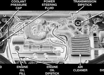
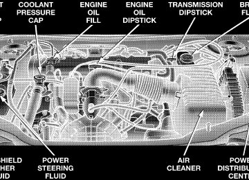
m 2.4L Engine . . . . . . . . . . . . . . . . . . . . . . . . . . 189
m 2.7L Engine . . . . . . . . . . . . . . . . . . . . . . . . . . 190
m Onboard Diagnostic System — OBD II . . . . . . 191
m Emissions Inspection And MaintenancePrograms . . . . . . . . . . . . . . . . . . . . . . . . . . . . 192
m Replacement Parts . . . . . . . . . . . . . . . . . . . . . 193
m Dealer Service . . . . . . . . . . . . . . . . . . . . . . . . 193
m Maintenance Procedures . . . . . . . . . . . . . . . . . 194
N Engine Oil . . . . . . . . . . . . . . . . . . . . . . . . . . 194
N Crankcase Emission Control System . . . . . . . . 200
N Maintenance-Free Battery . . . . . . . . . . . . . . . . 200
N Air Conditioner . . . . . . . . . . . . . . . . . . . . . . 201N Power Steering Fluid Check . . . . . . . . . . . . . . 202
N Suspension Ball Joints . . . . . . . . . . . . . . . . . . 203
N Body Mechanism Lubrication . . . . . . . . . . . . . 203
N Windshield Wiper Blades . . . . . . . . . . . . . . . . 205
N Windshield Washers . . . . . . . . . . . . . . . . . . . 205
N Exhaust System . . . . . . . . . . . . . . . . . . . . . . 206
N Cooling System . . . . . . . . . . . . . . . . . . . . . . . 207
N Hoses And Vacuum/Vapor Harnesses . . . . . . . 211
N Brakes . . . . . . . . . . . . . . . . . . . . . . . . . . . . . 211
N Fuel System Hoses . . . . . . . . . . . . . . . . . . . . 213
N Automatic Transmission . . . . . . . . . . . . . . . . 213188 MAINTAINING YOUR VEHICLE
N Appearance Care And Protection From
Corrosion . . . . . . . . . . . . . . . . . . . . . . . . . . . 216
m Convertible Top Care . . . . . . . . . . . . . . . . . . . 221
N Washing . . . . . . . . . . . . . . . . . . . . . . . . . . . . 221
N General Cleaning . . . . . . . . . . . . . . . . . . . . . 221
N Cloth Top Additional Cleaning Procedure . . . . 222
N Cloth Top Protection . . . . . . . . . . . . . . . . . . . 222
N Weather Strip Care . . . . . . . . . . . . . . . . . . . . 222
m Fuses . . . . . . . . . . . . . . . . . . . . . . . . . . . . . . . 223N Underhood Fuses
(Power Distribution Center) . . . . . . . . . . . . . . 223
N Interior Fuses . . . . . . . . . . . . . . . . . . . . . . . . 223
m Replacement Light Bulbs . . . . . . . . . . . . . . . . 225
m Bulb Replacement . . . . . . . . . . . . . . . . . . . . . . 226N Headlight Bulb Replacement N Park, Turn Signal, Sidemarker Bulb
. . . . . . . . . . . . . 226
Replacement . . . . . . . . . . . . . . . . . . . . . . . . . 228
N Fog Light Bulb Replacement . . . . . . . . . . . . . 229
N Center Stoplight Bulb Replacement . . . . . . . . . 230
N Rear Light Bulb Replacement . . . . . . . . . . . . . 230
N License Plate Bulb Replacement . . . . . . . . . . . 231
N Headlight Aiming . . . . . . . . . . . . . . . . . . . . . 232
m Fluids And Capacities . . . . . . . . . . . . . . . . . . . 232
m Recommended Fluids, Lubricants AndGenuine Parts . . . . . . . . . . . . . . . . . . . . . . . . . 233
N Engine . . . . . . . . . . . . . . . . . . . . . . . . . . . . . 233
N Chassis . . . . . . . . . . . . . . . . . . . . . . . . . . . . 2332.4L ENGINE
MAINTAINING YOUR VEHICLE 189
190 MAINTAINING YOUR VEHICLE
2.7L ENGINE
ONBOARD DIAGNOSTIC SYSTEM — OBD II Your vehicle is equipped with a sophisticated onboard diagnostic system called OBD II. This system monitors the performance of the emissions, engine, and automatic transmission control systems. When these systems are operating properly, your vehicle will provide excellent performance and fuel economy, as well as engine emis- sions well within current government regulations. If any of these systems require service, the OBD II system will turn on the “Malfunction Indicator Light.” It will also store diagnostic codes and other information to assist your service technician in making repairs. Al- though your vehicle will usually be drivable and not need towing, see your dealer for service as soon as possible.
MAINTAINING YOUR VEHICLE 191
CAUTION!
† Prolonged driving with the “Malfunction Indica- tor Light” on could cause further damage to the emission control system. It could also affect fuel economy and driveability. The vehicle must be serviced before any emissions tests can be per- formed. † If the “Malfunction Indicator Light” is flashing while the engine is running, severe catalytic con- verter damage and power loss will soon occur. Immediate service is required.
192 MAINTAINING YOUR VEHICLE
EMISSIONS INSPECTION AND MAINTENANCE PROGRAMS In some localities, it may be a legal requirement to pass an inspection of your vehicle’s emissions control system. Failure to pass could prevent vehicle registration.
For states which have an I/M (Inspection and Maintenance) requirement, this check verifies the following: the MIL (Malfunction Indicator Lamp) is functioning and is not on when the engine is running, and that the OBD (On Board Diagnostic) system is ready for testing. Normally, the OBD system will be ready. The OBD system may not be ready if your vehicle was recently serviced, if you recently had a dead battery, or a battery replacement. If the OBD system should be determined not ready for the I/M test, your vehicle may fail the test. Your vehicle has a simple ignition key actuated test which you can use prior to going to the test station. To check if your vehicle’s OBD system is ready, you must do the following: 1. Insert your ignition key into the ignition switch.
2. Turn the ignition to the ON position, but do not crank or start the engine. 3. If you crank or start the engine, you will have to start this test over. 4. As soon as you turn your key to the ON position, you will see your MIL symbol come on as part of a normal bulb check. 5. Approximately 15 seconds later, one of two things will happen:
a. The MIL will flash for about 10 seconds and then return to being fully illuminated until you turn off the ignition key or start the engine. This means that your vehicle’s OBD system is not ready and you should not proceed to the I/M station. b. The MIL will not flash at all and will remain fully illuminated until you turn off the ignition key or start the engine. This means that your vehicle’s OBD system is ready and you can proceed to the I/M station.
If your OBD system is not ready, you should see your authorized dealer or repair facility. If your vehicle was recently serviced or had a battery failure or replacement, you may need to do nothing more than drive your vehicle as you normally would in order for your OBD system to update. A recheck with the above test routine may then indicate that the system is now ready. Regardless of whether your vehicle’s OBD system is ready or not ready, if the MIL symbol is illuminated during normal vehicle operation, you should have your vehicle serviced before going to the I/M station. The I/M station can fail your vehicle because the MIL symbol is on with the engine running.
MAINTAINING YOUR VEHICLE 193
REPLACEMENT PARTS Use of genuine Mopar parts for normal/scheduled main- tenance and repairs is highly recommended to insure the designed performance. Damage or failures caused by the use of non-Mopar parts for maintenance and repairs will not be covered by the manufacturer’s warranty.
DEALER SERVICE Your dealer has the qualified service personnel, special tools and equipment to perform all service operations in an expert manner. Service manuals are available which include detailed service information for your vehicle. Refer to these manuals before attempting any procedure yourself. NOTE: systems can result against you.
Intentional tampering with emissions control in civil penalties being assessed
194 MAINTAINING YOUR VEHICLE
WARNING!
Engine Oil
You can be badly injured working on or around a motor vehicle. Do only that service work for which you have the knowledge and the proper equipment. If you have any doubt about your ability to perform a service job, take your vehicle to a competent mechanic.
MAINTENANCE PROCEDURES
The pages that follow contain the required maintenance services determined by the engineers who designed your vehicle. Besides the maintenance items for which there are fixed maintenance intervals, there are other items that should operate satisfactorily without periodic maintenance. However, if a malfunction of these items does occur, it could adversely affect the engine or vehicle performance. These items should be inspected if a malfunction is observed or suspected.
Checking Oil Level To assure proper lubrication of your vehicle’s engine, the engine oil must be maintained, at the correct level. Check the oil level at regular intervals, such as every fuel stop. The best time to check the oil level is about 5 minutes after a fully warmed engine is shut off or before starting the engine after it has sat overnight. Checking the oil while the vehicle is on level ground will improve the accuracy of the oil level readings. Maintain the oil level between the MIN and MAX markings on the dipstick. Adding one quart of oil when the reading is at the MIN mark will result in a MAX reading on these engines.
MAINTAINING YOUR VEHICLE 195
† Stop and Go driving † Extensive engine idling. † Driving in dusty conditions † Short trips of less than 10 miles (16.2 km) † More than 50% of your driving is at sustained high † Trailer towing † Taxi, Police or delivery service (commercial service)