- Download PDF Manual
-
holder mounted on the underside of the cover. The bottom of the console bins also have built in holders for compact discs or cassette tapes.
134 UNDERSTANDING THE FEATURES OF YOUR VEHICLE
Rear Cargo Storage Bin The storage bin is located in the floor of the rear cargo area. To open lift up on the handle.
Retractable Cargo Area Cover — If Equipped To cover the cargo area: 1. Fold down the third row seatbacks. 2. Unfold the cargo cover extensions and lock into place. 3. Insert the pins on the ends of the cover into the slots located on the trim panel behind the second row seat- backs. 4. Grasp the center portion of the cover flap. Pull it over the cargo area. 5. Insert the pins on the ends of the cover flap into the slots on the rear trim panel. 6. The liftgate may be opened or closed with the cargo cover in place.
WARNING!
In an accident a cargo cover loose in the vehicle could cause injury. It could fly around in a sudden stop and strike someone in the vehicle. Do not store the cargo cover on the cargo floor or in the passenger compartment. Remove the cover from the vehicle when taken from its mounting. Do not store in the vehicle.
Stowed Position 1. Fold down the third row seatbacks. 2. Fold the cargo cover extensions to their stowed posi- tion and lock into place.
UNDERSTANDING THE FEATURES OF YOUR VEHICLE 135
3. Insert the pins on the ends of the cover into the slots located on the trim panel behind the third row seatbacks. 4. Grasp the center portion of the cover flap. Pull it over the cargo area. 5. Insert the pins on the ends of the cover flap into the slots on the rear trim panel. 6. The liftgate may be opened or closed with the cargo cover in place. Cargo Tie-Down Hooks The tie-downs located on cargo area floor and on the rear trim panels should be used to safely secure loads when vehicle is moving.
136 UNDERSTANDING THE FEATURES OF YOUR VEHICLE
WARNING!
• Cargo tie-down hooks are not safe anchors for a child seat tether strap. In a sudden stop or colli- sion a hook could pull loose and allow the child seat to come loose. A child could be badly injured. Use only the anchors provided for child seat tethers. • The weight and position of cargo and passengers can change the vehicle center of gravity and vehicle handling. To avoid loss of control result- ing in personal injury, follow these guidelines for loading your vehicle:
• Always place cargo evenly on the cargo floor. Put heavier objects as low and as far forward as possible.
• Place as much cargo as possible in front of the rear axle. Too much weight or improperly placed weight over or behind the rear axle can cause the rear of the vehicle to sway. • Do not pile luggage or cargo higher than the top of the seatback. This could impair visibility or become a dangerous projectile in a sudden stop or collision.
WARNING!
To help protect against personal injury, passengers should not be seated in the rear cargo area. The rear cargo space is intended for load carrying purposes only, not for passengers, who should sit in seats and use seat belts.
ROOF LUGGAGE RACK — IF EQUIPPED The crossbars and siderails are designed to carry the weight on vehicles equipped with a luggage rack. The load must not exceed 150 lbs (68 kg), and should be uniformly distributed over the luggage rack crossbars.
Distribute cargo weight evenly on the roof rack crossbars. The roof rack does not increase the total load carrying capacity of the vehicle. Be sure the total load of cargo
UNDERSTANDING THE FEATURES OF YOUR VEHICLE 137
inside the vehicle plus that on the external rack does not exceed the maximum vehicle load capacity. To move the cross bars, press the upper edge of each cross bar button, then move the cross bar to the desired position. This is can be done with one person standing on each side of the vehicle, moving the cross bar at the same time. Once the cross bar is in place, press the lower edge of the cross bar button to lock it into position. Attempt to move the crossbar again to ensure that it has properly locked into position. NOTE: To reduce the amount of wind noise when the cross bars are not in use, move both cross bars next to each other towards the rear of the vehicle in the rear most position. The tie down holes on the cross bar ends should always be used to tie down the load. Check the straps frequently to be sure that the load remains securely attached.
138 UNDERSTANDING THE FEATURES OF YOUR VEHICLE
CAUTION!
• To avoid damage to the roof rack and vehicle, do not exceed the maximum roof rack load capacity of 150 lbs (68 kg). Always distribute heavy loads as evenly as possible and secure the load appro- priately. • Long loads which extend over the windshield, such as wood panels or surfboards, or loads with large frontal area should be secured to both the front and rear of the vehicle. • Travel at reduced speeds and turn corners care- fully when carrying large or heavy loads on the roof rack. Wind forces, due to natural causes or nearby truck traffic, can add sudden upward loads. This is especially true on large flat loads and may result in damage to the cargo or your vehicle.
WARNING!
Cargo must be securely tied before driving your ve- hicle. Improperly secured loads can fly off the vehicle, particularly at high speeds, resulting in personal in- jury or property damage. Follow the Roof Rack Cau- tions when carrying cargo on your roof rack.
LOAD LEVELING SYSTEM The automatic load leveling system will provide a level riding vehicle under most passenger and cargo loading conditions. A hydraulic pump contained within the shock absorbers raises the rear of the vehicle to the correct height. It takes approximately 1 mile (1.6 km) of driving for the leveling to complete depending on road surface conditions. If the leveled vehicle is not moved for approximately 15
hours, the leveling system will bleed itself down. The vehicle must be driven to reset the system.UNDERSTANDING YOUR INSTRUMENT PANEL
CONTENTS
䡵 Instruments And Controls . . . . . . . . . . . . . . . . . 142
䡵 Instrument Cluster . . . . . . . . . . . . . . . . . . . . . . 143
䡵 Instrument Cluster Descriptions . . . . . . . . . . . . 144
䡵 Electronic Vehicle Information Center (EVIC) . . . 151▫ Customer Programmable Features —
If Equipped . . . . . . . . . . . . . . . . . . . . . . . . . 154
▫ Compass Display — If Equipped . . . . . . . . . . 157
▫ Mini-Trip Functions — If Equipped . . . . . . . . 159
䡵 Setting The Analog Clock . . . . . . . . . . . . . . . . . 160䡵 Electronic Digital Clock . . . . . . . . . . . . . . . . . . 160
▫ Clock Setting Procedure . . . . . . . . . . . . . . . . . 160
䡵 Sales Code RAH—AM & FM Stereo Radio With CD Player And CD/DVD Changer Controls . . . . . . . 161
▫ Radio Operation . . . . . . . . . . . . . . . . . . . . . . 161
▫ CD Player Operation . . . . . . . . . . . . . . . . . . . 163
▫ CD/DVD Changer Operation . . . . . . . . . . . . . 165䡵 Sales Code RBP—AM & FM Stereo Radio With Cassette Tape Player, CD Player, And Optional CD/DVD Changer Controls . . . . . . . . . . . . . . . 165
140 UNDERSTANDING YOUR INSTRUMENT PANEL
▫ Radio Operation . . . . . . . . . . . . . . . . . . . . . . 166
▫ Tape Player Operation . . . . . . . . . . . . . . . . . . 170
▫ CD Player Operation . . . . . . . . . . . . . . . . . . . 172
▫ CD/DVD Changer Operation — If Equipped . 173
䡵 6 Disc CD/DVD Changer (Rdv) — If Equipped . 175
▫ Operating Instructions — CD/DVD Changer . . 175
▫ Eject (EJT) Button . . . . . . . . . . . . . . . . . . . . . 177
▫ Operating Instructions — Remote Control . . . . 178
▫ Operating Instructions — Video Screen . . . . . . 182
▫ Operating Instructions — Headphones . . . . . . 183
▫ Operating Instructions — MP3 Player, PortableWalkman . . . . . . . . . . . . . . . . . . . . . . . . . . . 185
▫ Operating Instructions — Video
Games/Camcorders
. . . . . . . . . . . . . . . . . . . 185
䡵 Satellite Radio — If Equipped . . . . . . . . . . . . . . 186
▫ System Activation . . . . . . . . . . . . . . . . . . . . . 186
▫ Electronic Serial Number/Sirius IdentificationNumber (ENS/SID) . . . . . . . . . . . . . . . . . . . . 186
▫ Selecting Satellite Mode In RBB, RAH And RBK
Radios . . . . . . . . . . . . . . . . . . . . . . . . . . . . . 187
▫ Selecting Satellite Mode In RBP, RBU, RAZ, And
RBQ Radios . . . . . . . . . . . . . . . . . . . . . . . . . 187
▫ Selecting a Channel . . . . . . . . . . . . . . . . . . . . 188
▫ Storing And Selecting Pre-Set Channels . . . . . . 188
▫ Using The PTY (Program Type) Button(If Equipped)
. . . . . . . . . . . . . . . . . . . . . . . . 188
▫ PTY Button ⬙Scan⬙ . . . . . . . . . . . . . . . . . . . . . 188
▫ PTY Button ⬙Seek⬙ . . . . . . . . . . . . . . . . . . . . . 189▫ Satellite Antenna . . . . . . . . . . . . . . . . . . . . . . 189
▫ Reception Quality . . . . . . . . . . . . . . . . . . . . . 189
䡵 Remote Sound System Controls . . . . . . . . . . . . . 190
▫ Radio Operation . . . . . . . . . . . . . . . . . . . . . . 190
▫ Tape Player . . . . . . . . . . . . . . . . . . . . . . . . . 190
▫ CD Player . . . . . . . . . . . . . . . . . . . . . . . . . . 191
䡵 Radio General Information . . . . . . . . . . . . . . . . 191
▫ Radio Broadcast Signals . . . . . . . . . . . . . . . . . 191
▫ Two Types Of Signals . . . . . . . . . . . . . . . . . . 191
▫ Electrical Disturbances . . . . . . . . . . . . . . . . . . 191UNDERSTANDING YOUR INSTRUMENT PANEL 141
▫ AM Reception . . . . . . . . . . . . . . . . . . . . . . . 192
▫ FM Reception . . . . . . . . . . . . . . . . . . . . . . . . 192
䡵 Cassette Tape And Player Maintenance . . . . . . . 192
䡵 CD/DVD Disc Maintenance . . . . . . . . . . . . . . . 193
䡵 Radio Operation And Cellular Phones . . . . . . . . 194
䡵 Navigation System — If Equipped . . . . . . . . . . . 194
䡵 Climate Controls . . . . . . . . . . . . . . . . . . . . . . . 195
▫ Dual-Zone Automatic Temperature Control . . . 195
▫ Electric Rear Window Defroster . . . . . . . . . . . 205142 UNDERSTANDING YOUR INSTRUMENT PANEL
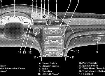
INSTRUMENTS AND CONTROLS
INSTRUMENT CLUSTER
UNDERSTANDING YOUR INSTRUMENT PANEL 143
144 UNDERSTANDING YOUR INSTRUMENT PANEL
INSTRUMENT CLUSTER DESCRIPTIONS
1. Voltage Light
This light monitors the electrical system voltage. The light should turn on momentarily as the engine is started. If the light stays on or turns on while driving, it indicates a problem with the charging system. Immediate service should be obtained. 2. Temperature Gauge The temperature gauge shows engine coolant tempera- ture. Any reading within the normal range indicates that the engine cooling system is operating satisfactorily. The gauge pointer will likely indicate a higher tempera- ture when driving in hot weather, up mountain grades, or when towing a trailer. It should not be allowed to exceed the upper limits of the normal operating range.
CAUTION!
Driving with a hot engine cooling system could damage your vehicle. If temperature gauge reads (H), pull over and stop the vehicle. Idle the vehicle with the air conditioner turned off until the pointer drops back into the normal range. If the pointer remains on the “H”, and you hear continuous chimes, turn the engine off immediately, and call for service.
WARNING!
A hot engine cooling system is dangerous. You or others could be badly burned by steam or boiling coolant. You may want to call a service center if your vehicle overheats. If you decide to look under the hood yourself, see Section 7 of this manual. Follow the warnings under the Cooling System Pressure Cap paragraph.
3. Fuel Gauge The pointer shows the level of fuel in the fuel tank when the ignition switch is in the ON position.
The Low Fuel Light will turn on when the fuel level reaches approximately 2 to 4 gallons (7 to 15 liters) this light will remain on until fuel is added.
UNDERSTANDING YOUR INSTRUMENT PANEL 145
4. Turn Signal Indicators
The arrow will flash with the exterior turn signal when the turn signal lever is operated.
If the vehicle electronics sense that the vehicle has traveled about one mile with the turn signals on, a chime will sound to alert you to turn the signals off. If either indicator flashes at a rapid rate, check for a defective outside light bulb. 5. Speedometer Indicates vehicle speed. 6. Anti-Lock Light
This light monitors the Anti-Lock Brake Sys- tem. The light will turn on when the ignition switch is turned to the ON position and may stay on for as long as four seconds.
If the ABS light remains on or turns on while driving, it indicates that the Anti-Lock portion of the brake system
146 UNDERSTANDING YOUR INSTRUMENT PANEL
is not functioning and that service is required. However, the conventional brake system will continue to operate normally if the BRAKE warning light is not on. If the ABS light is on, the brake system should be serviced as soon as possible to restore the benefits of Anti-Lock brakes. If the ABS light does not turn on when the Ignition switch is turned to the ON position, have the light inspected by an authorized dealer. 7. Brake System Warning Light
This light monitors various brake functions, including brake fluid level and parking brake application. If the brake light turns on, it may indicate that the parking brake is applied, there is a low brake fluid level or there is a problem with the anit-lock brake system. The dual brake system provides a reserve braking capac- ity in the event of a failure to a portion of the hydraulic system. Failure of either half of the dual brake system is
indicated by the Brake Warning Light which will turn on when the brake fluid level in the master cylinder has dropped below a specified level. The light will remain on until the cause is corrected. NOTE: The light may flash momentarily during sharp cornering maneuvers which change fluid level condi- tions. The vehicle should have service performed. If brake failure is indicated, immediate repair is neces- sary.
WARNING!
Driving a vehicle with the brake light on is danger- ous. Part of the brake system may have failed. It will take longer to stop the vehicle. You could have an accident. Have the vehicle checked immediately.
Vehicles equipped with Anti-Lock brakes (ABS), are also equipped with Electronic Brake Force Distribution (EBD). In the event of an EBD failure, the Brake Warning Light will turn on along with the ABS Light. Immediate repair to the ABS system is required. The operation of the Brake Warning Light can be checked by turning the ignition switch from the OFF position to the ON position. The light should illuminate for approxi- mately two seconds. The light should then turn off unless the parking brake is applied or a brake fault is detected. If the light does not illuminate, have the light inspected by an authorized dealer. The light also will turn on when the parking brake is applied with the ignition switch in the ON position. NOTE: This light shows only that the parking brake is applied. It does not show the degree of brake application.
UNDERSTANDING YOUR INSTRUMENT PANEL 147
8. Traction Control Indicator — If Equipped
This display indicator illuminates momentarily as a bulb check when the ignition switch is first turned ON.
the system OFF.
The traction control Indicator will turn on if: • The traction control system is in use. • The Traction Control switch has been used to turn • There is a Traction Control System malfunction. • The system has been deactivated to prevent damage to the brake system due to overheated brake tem- peratures.
NOTE: Extended heavy use of Traction Control may cause the system to deactivate and turn on the Traction Control Light. This is to prevent overheating of the brake system and is a normal condition. The system will remain
148 UNDERSTANDING YOUR INSTRUMENT PANEL
disabled for about 4 minutes until the brakes have cooled. The system will automatically reactivate and turn off the Traction Control Light. 9. Tachometer The red segments indicate the maximum permissible engine revolutions-per-minute (r.p.m. x 1000) for each gear range. Before reaching the red area, ease up on the accelerator. 10. Trip Odometer Button Press this button to change the display from odometer to either of the two trip odometer settings. The word TRIP and either “A” or “B” will appear when in the trip odometer mode. Push in and hold the button for two seconds to reset the trip odometer to 0 miles or kilome- ters. The odometer must be in trip mode to reset. 11. Transmission Range Indicator This display indicator shows the automatic transmission gear selection.
12. AutoStick Light This display indicator illuminates when the gearshift lever is moved to the AutoStick position. 13. Odometer/Trip Odometer The odometer shows the total distance the vehicle has been driven. U.S. federal regulations require that upon transfer of vehicle ownership, the seller certify to the purchaser the correct mileage that the vehicle has been driven. There- fore, if the odometer reading is changed during repair or replacement, be sure to keep a record of the reading before and after the service so that the correct mileage can be determined. The two trip odometers show individual trip mileage. To switch from odometer to trip odometers, press and
release the Trip Odometer button. To reset a trip odom- eter, display the desired trip odometer to be reset then push and hold the button until the display resets (ap- proximately 2 seconds). 14. Cruise Indicator This display indicator shows that the Speed Control System is ON. 15. Malfunction Indicator Light
This light is part of an onboard diagnostic system called OBD that monitors engine and automatic transmission control systems. The light will illu- minate when the key is in the ON position before engine start. If the bulb does not come on when turning the key from OFF to ON, have the condition checked promptly. Certain conditions such as a loose or missing gas cap, poor fuel quality, etc. may illuminate the light after engine start. The vehicle should be serviced if the light
UNDERSTANDING YOUR INSTRUMENT PANEL 149
stays on through several of your typical driving cycles. In most situations the vehicle will drive normally and will not require towing. The Malfunction Indicator Light flashes to alert you to serious conditions that could lead to immediate loss of power or severe catalytic converter damage. The vehicle should be serviced as soon as possible if this occurs. 16. High Beam Light
This light shows that the headlights are on high beam. Pull the Multi-Function lever towards the steering wheel to switch the headlights from high or low beam. 17. Navigation Screen — If Equipped The navigation system provides maps, turn identifica- tion, selection menus and instructions for selecting a variety of destinations and routes. Refer to your “Navi- gation User’s Manual” for detailed operating instruc- tions.
150 UNDERSTANDING YOUR INSTRUMENT PANEL
18. Front Fog Light Indicator — If Equipped
This light shows the front fog lights are ON.
19. Oil Pressure Warning Light
This light shows low engine oil pressure. The light should turn on momentarily when the engine is started. If the light turns on while driving, stop the vehicle and shut off the engine as soon as possible. A continuous chime will sound when this light turns on. Do not operate the vehicle until the cause is corrected. This light does not show how much oil is in the engine. The engine oil level must be checked under the hood. 20. Seat Belt Reminder Light
When the ignition switch is first turned ON, this light will turn on for 5 to 8 seconds as a bulb check. During the bulb check, if the driver’s seat belt is unbuckled, a chime will sound. After the bulb check or when driving, if the driver seat belt remains unbuckled,
the Seat Belt Warning Light will flash or remain on continuously. Refer to ⬙Enhanced Driver Seat Belt Re- minder System (BeltAlert™)⬙ in the Occupant Restraints section for more information. 21. Tire Pressure Monitor Warning Light — If Equipped
This light will turn on when there is a Low tire pressure condition. The light will also turn on if a problem exist with any tire sensor. The light will remain on until the tire pressure is prop-
erly set or the problem with the sensor is corrected. This light will turn on momentarily as a bulb check when the engine is started. When the tire pressure monitoring system warning light is lit, one or more of your tires is significantly underin- flated. You should stop and check your tires as soon as possible, and inflate them to the proper pressure as indicated on the tire and loading information placard.
Driving on a significantly underinflated tire causes the tire to overheat and can lead to tire failure. Underinfla- tion also reduces fuel efficiency and tire tread life, and may affect the vehicle’s handling and stopping ability. Each tire, including the spare, should be checked monthly when cold and set to the recommended inflation pressure as specified in the tire and loading information placard and owner’s manual. 22. Airbag Light
This light turns on and remains on for 6 to 8
seconds as a bulb check when the ignition switch is first turned ON. If the light is not on during starting, stays on, or turns on while driving, have the system inspected by an authorized dealer as soon as possible.UNDERSTANDING YOUR INSTRUMENT PANEL 151
23. Electronic Vehicle Information Center Display When the appropriate conditions exist, this display shows the Electronic Vehicle Information Center (EVIC) messages. 24. Engine Temperature Warning Light
This light warns of an overheated engine condi- tion. If this light is accompanied by a continuous chime, the engine temperature is critically hot, and the vehicle should be turned off immediately. The vehicle should be serviced as soon as possible.
ELECTRONIC VEHICLE INFORMATION CENTER (EVIC) The Electronic Vehicle Information Center (EVIC) con- sists of the following: • Vehicle information warning message displays • Tire Pressure Monitor System — If Equipped • Customer programmable features
152 UNDERSTANDING YOUR INSTRUMENT PANEL
• Compass display — If Equipped • Mini-Trip functions — If Equipped Pressing the MENU button will change the displayed programming features. Pressing the STEP button will display the available choices. Pressing the MENU button a second time accepts a selected choice. When the appropriate conditions exist, the Electronic Vehicle Information Center (EVIC) displays the following messages. • LEFT/RIGHT TURN SIGNAL ON (with a continuous • INVALID KEY & FOB (with a single chime) • SERVICE IMMOBILIZER (with a single chime) • KEY FOB BATTERY LOW (with a single chime) • KEY & FOB PROGRAMMED (with a single chime)
warning chime)
chime)
PARK (with a single chime)
• PROGRAM KEY & FOB • MEMORY #1/#2 POSITION SET (with a single chime) • MEMORY #1/#2 POS SELECTED • MEMORY SYSTEM DISABLED VEHICLE NOT IN • SET INHIBITED DUE TO MOTION (with a single • FOB LINKED (with a single chime) • FOB UNLINKED (with a single chime) • PARK BRAKE ENGAGED (with a single chime) • LOW BRAKE FLUID (with a single chime) • LOW FUEL (with a single chime) • MENU IN PARK ONLY • LIST # ALERT MESSAGES
chime)
• UNLOCK TO OPEN LIFTGATE (with a single chime) • PUT IN PARK FOR LIFTGATE (with a single chime) • TOO COLD FOR PWR LIFTGATE (with a single • TOO HOT FOR PWR LIFTGATE (with a single chime) • PERFORM SERVICE (with a single chime) • LEFT/RIGHT FRONT DOOR AJAR (one or more, • LEFT/RIGHT REAR DOOR AJAR (one or more, with a single chime if speed is above 1 mph) • DOOR(S) AJAR (with a single chime) • DOOR(S) AND GATE AJAR (with a single chime) • LIFT GATE AJAR (with a single chime if speed is
with a single chime if speed is above 1 mph)
above 1 mph)
UNDERSTANDING YOUR INSTRUMENT PANEL 153
chime)
• WASHER FLUID LOW (with a single chime) • PEDAL ADJUST DISABLED CRUISE ENGAGED • PEDAL ADJUST DISABLED VEHICLE IN REVERSE • CHANNEL 1, 2, OR 3 TRANSMIT (with a single • CHANNEL 1, 2, OR 3 TRAINING (with a single • CHANNEL 1, 2, OR 3 TRAINED (with a single chime) • CLEARING CHANNELS • CHANNELS CLEARED • CHANNELS DEFAULTED • DID NOT TRAIN • 1,2,3 OR 4 TIRE(S) LOW PRESSURE (Refer to “Starting
chime)
And Operating, Tire Section”)
154 UNDERSTANDING YOUR INSTRUMENT PANEL
And Operating, Tire Section”)
ing And Operating, Tire Section”)
• 1,2,3 OR 4 TIRE(S) HIGH PRESSURE (Refer to “Start- • SERVICE TIRE SYSTEM SOON (Refer to “Starting • TIRE PRESSURE UNAVAILABLE (Refer to “Starting • TCS SUSPENDED (Traction Control System, with a • TCS ACTIVE (Traction Control System, with a • SERVICE TCS SYSTEM (Traction Control System, with
And Operating, Tire Section”)
graphic and single chime)
graphic)
a graphic and single chime)
Customer Programmable Features — If Equipped Press the MENU button until one of the following display choices appears: Language? When in this display you may select one of three lan- guages for all display nomenclature, including the trip computer functions and navigation system. Press the STEP button while in this display selects English, Francais, or Espanol. As you continue the displayed information will be shown in the selected language. Display U.S. or Metric? Pressing the US/M button will change the EVIC, odom- eter, navigation system and A/C Control units from US to Metric. Use factory Settings? When in this display you may select to use the factory settings and no programmable features will be offered.
Auto Door Locks? When this feature is selected, all doors and the liftgate lock automatically when the speed of the vehicle reaches 15 mph (25 km/h). Pressing the STEP button when in this display will select “Yes” or “No.” Auto Unlock On Exit? When this feature is selected all the vehicle’s doors will unlock when the driver’s door is opened if the vehicle is stopped and the transmission is in P (Park) or N (Neu- tral) position. Pressing the STEP button when in this display will select “Yes” or “No.” Remote Unlock Driver’s Door 1st? When this feature is selected only the driver’s door will unlock on the first press of the remote keyless entry unlock button and require a second press to unlock the remaining locked doors and liftgate. When REMOTE UNLOCK ALL DOORS is selected all of the doors and the liftgate will unlock at the first press of the remote
UNDERSTANDING YOUR INSTRUMENT PANEL 155
keyless entry unlock button. Pressing the STEP button when in this display will select DRIVER’S DOOR 1ST or ALL DOORS. Remote Linked To Memory? (Available with Memory Seat Only) When this feature is selected the memory seat, mirror, and radio settings will return to the memory set position when the remote keyless entry “Unlock” button is pressed. If this feature is not selected then the memory seat, mirror, and radio settings can only return to the memory set position using the door mounted switch. Pressing the STEP button when in this display will select “Yes” or “No.” Sound Horn On Lock? When this feature is selected a short horn sound will occur when the remote keyless entry “Lock” button is pressed. This feature may be selected with or without the
156 UNDERSTANDING YOUR INSTRUMENT PANEL
flash lights on lock/unlock feature. Pressing the STEP button when in this display will select “Yes” or “No.” Flash Lights On Lock/Unlock? When this feature is selected, the front and rear turn signals will flash when the doors are locked or unlocked using the remote keyless entry transmitter. This feature may be selected with or without the sound horn on lock feature selected. Pressing the STEP button when in this display will select “Yes” or “No.” Headlamp Delay When this feature is selected the driver can choose, when exiting the vehicle, to have the headlamps remain on for 30, 60, or 90 seconds, or not remain on. Pressing the STEP button when in this display will select 30, 60, 90, or OFF. Headlamp On With Wipers? (Available with Auto Headlights Only) When this feature is selected and the headlight switch has at least once been moved to the AUTO position, the
headlights will turn on in approximately 10 seconds when the wipers are turned on. The headlights will also turn off when the wipers are turned off if they were turned on in this way. Pressing the STEP button when in this display will select “Yes” or “No.” NOTE: Turning the headlights on during the daytime causes the instrument panel lights to dim. To increase the brightness, refer to “Lights” in this section. Service Interval When this feature is selected a service interval between 2,000 miles (3 200 km) and 6, 000 miles (10 000 km) in 500
mile (800 km) increments may be selected. Pressing the STEP button when in this display will select distances between 2,000 miles (3 200 km) and 6, 000 miles (10 000
km) in 500 mile (800 km) increments.Reset Service Distance (Displays Only if Service Interval was Changed) When this feature is selected the current accumulated service distance can be reset to the newly selected service interval. Pressing the STEP button when in this display will select “Yes” or “No.” Power Accessory Delay? When this feature is selected, the power window switches, radio, hands–free system, DVD video system, power sunroof, and power outlets will remain active for up to 45 seconds after the ignition switch has been turned off. Opening a vehicle door or liftgate will cancel this feature. Easy Exit Seat? (Available with Memory Seat Only) When this feature is selected, the driver’s seat moves rearward 5 cm (2 inches) or to the farthest rearward position if this distance is less than 5 cm (2 inches) when the key is removed from the ignition switch so that the
UNDERSTANDING YOUR INSTRUMENT PANEL 157
driver can more easily exit the vehicle. The seat will return to the memorized seat location (if REMOTE LINK TO MEMORY is set to YES) when the remote keyless entry transmitter is used to unlock the door. Pressing the STEP button when in this display will select “Yes” or “No.” Retrain Tire Sensors (Available with Tire Pressure Monitor System Only) The Tire Pressure Monitor system must be retrained following a tire rotation or wheel rim mounted sensor replacement. See your authorized dealer for service. Compass Display — If Equipped This display provides one of eight compass readings to indicate the direction the vehicle is facing.
158 UNDERSTANDING YOUR INSTRUMENT PANEL
Automatic Compass Calibration This compass is self calibrating which eliminates the need to manually set the compass. When the vehicle is new, the compass may appear erratic and the EVIC will display “COMPASS CALIBRATING” until the compass is calibrated. The compass will calibrate automatically after approximately 40 seconds if no buttons are pressed and the vehicle is in Park. You may also calibrate the compass by completing one 360° turn in an area free from large metal or metallic objects, the “COMPASS CALI- BRATING” EVIC message will turn off and the compass will function normally. Manual Compass Calibration If the compass appears erratic and the “COMPASS CALI- BRATING” message does not appear in the EVIC display, you must put the compass into the Calibration Mode manually.
To put into a Calibration Mode: Turn on the ignition switch and set the display to Compass. Press the RESET button for at least 10 seconds until the “COMPASS CALIBRATING” message appears. Release the RESET button and complete one 360° turn in an area free from large metal objects. The “COMPASS CALIBRATING” message will turn off and the compass will function normally. Compass Variance Compass Variance is the difference between magnetic North and Geographic North. In some areas of the country, the difference between magnetic and geographic North is great enough to cause the compass to give false readings. If this occurs, the compass variance must be set. NOTE: Magnetic materials should be kept away from the overhead console.
UNDERSTANDING YOUR INSTRUMENT PANEL 159
To set the variance: Turn the ignition switch ON and set the display to Compass. Press the RESET button for approximately 5 seconds but no more than 10 seconds. The “COMPASS VARIANCE” message and the last vari- ance zone number will be displayed. Press the STEP button to select the proper variance zone as shown in the map. Press the RESET button to set the new variance zone and resume normal operation. Mini-Trip Functions — If Equipped This displays information on the following: • Average Fuel Economy (ECO AVG) Shows the average fuel economy since the last reset. The minimum average fuel economy that will be displayed on reset is 0.3 mpg. • Distance To Empty (DTE) Shows the estimated distance that can be travelled with the fuel remaining in the tank. This estimated distance is determined using the MPG for the last few minutes.
160 UNDERSTANDING YOUR INSTRUMENT PANEL
• Off Mode Shows a blank display. • Step Button Push this button to cycle through all functions. To Reset The Display Pressing and releasing the Reset button once will clear the resettable function currently being displayed. The resettable function is average fuel economy. Reset will only occur if the resettable function is currently being displayed.
the Mini-trip
SETTING THE ANALOG CLOCK To set the analog clock at the top center of the instrument panel, press and hold the button until the setting is correct.
ELECTRONIC DIGITAL CLOCK
The clock and radio each use the display panel built into the radio. A digital readout shows the time in hours and minutes whenever the ignition switch is in the ON or ACC position and the time button is pressed. When the ignition switch is in the OFF position, or when the radio frequency is being displayed, time keeping is accurately maintained. Clock Setting Procedure
1. Turn the ignition switch to the ON or ACC position and press the time button. Using the tip of a ballpoint pen or similar object, press either the hour (H) or minute (M) buttons on the radio. 2. Press the H button to set hours or the M button to set minutes. The time setting will increase each time you press a button.
SALES CODE RAH—AM & FM STEREO RADIO WITH CD PLAYER AND CD/DVD CHANGER CONTROLS
UNDERSTANDING YOUR INSTRUMENT PANEL 161
Radio Operation
Power/Volume Control Press the ON/VOL control to turn the radio on. Turn the volume control clockwise to increase the volume. NOTE: Power to operate the radio is supplied through the ignition switch. It must be in the ON or ACC position to operate the radio. Mode Press the MODE button to select between, AM, FM, CD, CD/DVD changer or the Satellite Radio (if equipped). When the Satellite Radio (if equipped) is selected “SA” will appear in your radio display. A disc may remain in the radio while in the Satellite or radio mode. Seek Press and release the SEEK button to search for the next station in either the AM, FM or Satellite mode. Press the
162 UNDERSTANDING YOUR INSTRUMENT PANEL
top of the button to seek up and the bottom to seek down. The radio will remain tuned to the new station until you make another selection. Holding the button in will by- pass stations without stopping until you release it. Tuning Press the TUNE control up or down to increase or decrease the frequency. If you press and hold the button, the radio will continue to tune until you release the button. The frequency will be displayed and continu- ously updated while the button is pressed. Balance The Balance control adjusts the left-to-right speaker bal- ance. Press the AUDIO button, select BALANCE, then turn the volume knob to adjust the balance. Fade The Fade control provides for balance between the front and rear speakers. Press the AUDIO button, select FADE, then turn the volume knob to adjust the fade balance.
Tone Control The Bass and/or Treble controls sound for the desired tone. Press the AUDIO button, select Bass or TREBLE, then turn the volume knob to increase or decrease amplification of the band. To Set The Radio Push-Button Memory When you are receiving a station that you wish to commit to push-button memory, press the SET button. SET 1 will show in the display window. Select the push-button you wish to lock onto this station and press and release that button. If a station is not selected within 5 seconds after pressing the SET button, the station will continue to play but will not be locked into push-button memory. You may add a second station to each push-button by repeating the above procedure with this exception: Press the SET button twice and SET 2 will show in the display window. Each button can be set for SET 1 and SET 2 in
both AM and FM. This allows a total of 10 AM and 10 FM stations to be locked into memory. You can recall the stations stored in SET 2 memory by pressing the push- button twice. To Change From Clock To Radio Mode Press the TIME button to change the display between radio frequency and time. General Information This radio complies with Part 15 of FCC rules and with RSS-210 of Industry Canada. Operation is subject to the following conditions: 1. This device may not cause harmful interference, 2. This device must accept any interference received, including interference that may cause undesired opera- tion.
UNDERSTANDING YOUR INSTRUMENT PANEL 163
NOTE: Changes or modifications not expressively ap- proved by the party responsible for compliance could void the user’s authority to operate the equipment. CD Player Operation
NOTE: The ignition switch must be in the ON or ACC position and the volume control ON before the CD player will operate. Inserting The Compact Disc
CAUTION!
This CD player will accept only 4–3/4 inch (12cm) discs only. The use of other sized discs may damage the CD player mechanism.
You may either insert or eject a disc with the radio OFF.
164 UNDERSTANDING YOUR INSTRUMENT PANEL
If you insert a disc with the ignition ON and the radio OFF, the display will show the time of day. If you insert a disc with the ignition OFF, the display will show the time of day for about 5 seconds, then go out. If the power is ON, the unit will switch from radio to CD mode and begin to play when you insert the disc. The display will show the track number and index time in minutes and seconds. Play will begin at the start of track 1. Seek Press the top of the SEEK button for the next selection on the CD. Press the bottom of the button to return to the beginning of the current selection, or return to the beginning of the previous selection if the CD is within the first 10 seconds of the current selection.
EJT — Eject Press the EJT button and the disc will unload and move to the entrance for easy removal. The unit will switch to the radio mode. If you do not remove the disc within 15 seconds, it will be reloaded. The radio mode will continue to appear. The disc can be ejected with the radio OFF. FF/TUNE/RW Press FF (Fast Forward) and the CD player will begin to fast forward until FF is released. The RW ( Reverse) button works in a similar manner. RND — Random Play Press the RND button while the CD is playing to activate Random Play. This feature plays the selections on the compact disc in random order to provide an interesting change of pace.
UNDERSTANDING YOUR INSTRUMENT PANEL 165
SALES CODE RBP—AM & FM STEREO RADIO WITH CASSETTE TAPE PLAYER, CD PLAYER, AND OPTIONAL CD/DVD CHANGER CONTROLS
Press the SEEK button to move to the next randomly selected track. Press TUNE FF to fast forward through the tracks. Press the FF button a second time to stop the fast forward feature. If TUNE RW is pressed, the current track will reverse to the beginning of the track and begin playing. Press the RND button a second time to stop Random Play. CD/DVD Changer Operation Press the MODE button to select between the CD player and the optional remote CD/DVD changer. Time Press the TIME button to change the display from elapsed CD or DVD playing time to time of day.
166 UNDERSTANDING YOUR INSTRUMENT PANEL
Radio Operation
Power/Volume Control Press the ON/VOL control to turn the radio on. Turn the volume control to the right to increase the volume. NOTE: Power to operate the radio is supplied through the ignition switch. It must be in the ON or ACC position to operate the radio. PTY (Program Type) Button Pressing this button once will turn on the PTY mode for 5 seconds. If no action is taken during the 5 second time out the PTY icon will turn off. Pressing the PTY button within 5 seconds will allow the program format type to be selected. Many radio stations do not currently broad- cast PTY information. Toggle the PTY button to select the following format types:
Program Type
Radio Display
Adult Hits Classical Classic Rock College Country Information Jazz Foreign Language News Nostalgia Oldies Personality Public Rhythm and Blues Religious Music Religious Talk
Adlt Hit Classicl Cls Rock College Country Inform Jazz Language News Nostalga Oldies Persnlty Public R & B Rel Musc Rel Talk
Program Type
Radio Display
Rock Soft Soft Rck Soft R&B Sports Talk Top 40
WeatherRock Soft Soft Rock Soft Rhythm and Blues Sports Talk Top 40
Weather By pressing the SEEK button when the PTY icon is displayed, the radio will be tuned to the next frequency station with the same selected PTY name. The PTY function only operates when in the FM and Satellite (if equipped) modes. The radio display will flash “SEEK” and the selected PTY program type when searching for the next PTY station. IfUNDERSTANDING YOUR INSTRUMENT PANEL 167
no station is found with the selected PTY program type, the radio will return to the last preset station. If a preset button is activated while in the PTY (Program Type) mode, the PTY mode will be exited and the radio will tune to the preset station. Pressing PTY, then SCAN will scan the FM Band and stop at all RDS stations that broadcast the station type. Each RDS station will be played for a 5 second scan once around the FM Band and stop at the last station. The PTY icon will then turn off. Seek Press and release the SEEK button to search for the next station in either the AM or FM mode. Press the top of the button to seek up and the bottom to seek down. The radio will remain tuned to the new station until you make another selection. Holding the button in will by- pass stations without stopping until you release it.
168 UNDERSTANDING YOUR INSTRUMENT PANEL
Scan Press and release the SCAN button to search for the next station in either the AM or FM mode. The radio will pause for 5 seconds at each listenable station before continuing to the next. To stop the search, press the SCAN button a second time. Tune Press the TUNE control up or down to increase or decrease the frequency. If you press and hold the button, the radio will continue to tune until you release the button. The frequency will be displayed and continu- ously updated while the button is pressed. Balance — BAL The Balance control adjusts the left-to-right speaker bal- ance. Press the BAL button in and it will pop out. Adjust the balance and push the button back in.
Fade The Fade control provides for balance between the front and rear speakers. Press the FADE button in and it will pop out. Adjust the balance and push the button back in. Tone Control The tone controls affect the BASS and TREBLE frequency bands. Each is controlled by a slider control with a detent at the mid position. Moving a control up or down increases or decreases amplification of the band. The mid position provides a balanced output. AM/FM Selection Press the AM/FM button to toggle between AM and FM mode. The operating mode will be displayed next to the station frequency. The display will show “ST” when a stereo station is received (FM only). To Set The Radio Push-Button Memory When you are receiving a station that you wish to commit to push-button memory, press the SET button.
SET 1 will now show in the display window. Select the “1–5” button you wish to lock onto this station and press and release that button. If a button is not selected within 5 seconds after pressing the SET button, the station will continue to play but will not be locked into push-button memory. You may add a second station to each push-button by repeating the above procedure with this exception: Press the SET button twice and SET 2 will show in the display window. Each button can be set for SET 1 and SET 2 in both AM and FM. This allows a total of 10 AM and 10 FM stations to be locked into push-button memory. The stations stored in SET 2 memory can be selected by pressing the push-button twice. Time Press the TIME button to change the display between radio frequency and time.
UNDERSTANDING YOUR INSTRUMENT PANEL 169
To set the clock, use a ballpoint pen or similar object to press the hour (H) or minute (M) buttons on the radio, The time setting will increase each time you press the button. Press any other button to exit from the clock setting mode. General Information This radio complies with Part 15 of FCC rules and with RSS-210 of Industry Canada. Operation is subject to the following conditions: 1. This device may not cause harmful interference, 2. This device must accept any interference received, including interference that may cause undesired opera- tion. NOTE: Changes or modifications not expressively ap- proved by the party responsible for compliance could void the user’s authority to operate the equipment.
170 UNDERSTANDING YOUR INSTRUMENT PANEL
Tape Player Operation Insert the cassette with the exposed tape side toward the right and the mechanical action of the player will gently pull the cassette into the play position. NOTE: When subjected to extremely cold temperatures, the tape mechanism may require a few minutes to warm up for proper operation. Sometimes poor playback may be experienced due to a defective cassette tape. Clean and demagnetize the tape heads at least twice a year. Tape Side — ⵜ⌬/PTY Pressing the ⵜ⌬ button during tape mode will cause the other side of the tape to be played. The display will confirm the selected tape play direction. The time is always displayed. Tape Press the TAPE button to select the Tape mode.
Seek Press the SEEK button up for the next selection on the tape and down to return to the beginning of the current selection. Press the SEEK button up or down to move the track number to skip forward or backward 1 to 7 selections. Press the SEEK button once to move 1 selection, twice to move 2 selections, etc. the display will show the total number of times the SEEK button was pushed. The SEEK function will be cancelled by pressing either the FF/RW or AM/FM button. Fast Forward — FF Press the FF button up momentarily to advance the tape in the direction that it is playing. The tape will advance until the button is pressed again or the end of the tape is reached. At the end of the tape, the tape will play in the opposite direction.
Rewind — RW Press the RW button down momentarily to reverse the tape direction. The tape will rewind until the button is pressed again or until the beginning of the tape is reached. At the beginning of the tape, the tape will play in the opposite direction. EJT Tape Press the EJT TAPE button and the cassette will disen- gage and eject from the radio. Metal Tape Selection (70µs) If a standard 70 µ (metal) tape is inserted into the player, the player will automatically select the correct equaliza- tion. Pinch Roller Release If ignition power or the radio ON/OFF switch are turned off, the pinch roller will automatically retract to protect
UNDERSTANDING YOUR INSTRUMENT PANEL 171
the tape from any damage. When power is restored to the tape player, the pinch roller will automatically reengage and the tape will resume play. Dolby Noise Reduction
The Dolby Noise Reduction System* is on when- ever the tape player is on, but may be switched
on/off. To turn the Dolby Noise Reduction System on/off: Press the Dolby NR button (button 2) after you insert the tape. The NR light in the display will go off when the Dolby System is off. * ”Dolby” noise reduction manufactured under license from Dolby Laboratories Licensing Corporation. Dolby and the double-D symbol are trademarks of Dolby Labo- ratories Licensing Corporation.
172 UNDERSTANDING YOUR INSTRUMENT PANEL
CD Player Operation
NOTE: The ignition switch must be in the ON or ACC position and the volume control ON before the CD player will operate. Inserting The Compact Disc You may either insert or eject a disc with the radio OFF. If you insert a disc with the ignition ON and the radio off, the display will show CD and the time of day will be displayed. If the power is on, the unit will switch from radio to CD mode and begin to play when you insert the disc. The display will show the track number and index time in minutes and seconds. Play will begin at the start of track 1. Seek Press the top of the SEEK button for the next selection on the CD. Press the bottom of the button to return to the
beginning of the current selection, or return to the beginning of the previous selection if the CD is within the first second of the current selection. Scan Press the SCAN button to play 10 seconds of each selection. Press the SCAN button a second time to cancel this feature. EJT CD Press the EJT CD button and the disc will unload and move to the entrance for easy removal. The unit will switch to the radio mode. If you do not remove the disc within 15 seconds, it will be reloaded. The unit will continue in radio mode. The disc can be ejected with the radio and ignition off.
FF/TUNE/RW Press FF (Fast Forward) and the CD player will begin to fast forward until FF is released. The RW (Reverse) button works in a similar manner. Random Play — RND/Program Button 4
Press the RND (button 4) button while the CD is playing to activate Random Play. This feature plays the selections on the compact disc in random order to provide an interesting change of pace. Press the top of the SEEK button to move to the next randomly selected track. Press the RND (button 4) button a second time to stop Random Play. MODE Press the MODE button to select between the CD player, remote CD/DVD changer (if equipped), or satellite radio (if equipped).UNDERSTANDING YOUR INSTRUMENT PANEL 173
To select Satellite Radio (if equipped), press the MODE button until the word SIRIUS™ appears. The following will be displayed in this order: After three seconds, the current channel name and number will be displayed for five seconds. The current program type and channel number will then be displayed for five seconds. The current channel name and number will then be displayed until an action occurs. A CD or tape may remain in the player while in the Satellite Radio mode. Time Press the TIME button to change the display from elapsed CD playing time to time of day. CD/DVD Changer Operation — If Equipped
MODE Press the MODE button to select between the CD player, and the CD/DVD changer (if equipped).
174 UNDERSTANDING YOUR INSTRUMENT PANEL
Disc Up/Program Button 1
Press the DISC (button 1) button to play the next avail- able disc. Random Play — RND/Program Button 4
Press the RND (button 4) button while the CD is playing to activate Random Play. This feature plays the selections on the currently playing compact disc in random order to provide an interesting change of pace. Press the top of the SEEK button to move to the next randomly selected track. Press the RND (button 4) button a second time to stop Random Play. FF/RW — TUNE Press and hold the FF button for fast forward. Press and hold the RW button for fast reverse. The audio output can be heard when fast forward and fast reverse are acti- vated.Disc Down/Program Button 5
Press the DISC (button 5) button to play the previous disc. Seek Press the top of the SEEK button for the next selection on the CD. Press the bottom of the button to return to the beginning of the current selection, or return to the beginning of the previous selection if the CD is within the first second of the current selection. Time Press the TIME button to switch between time of day and CD track time. Scan Press the SCAN button to play 10 seconds of each track. Press the SCAN button a second time to cancel the feature.6 DISC CD/DVD CHANGER (RDV) — IF EQUIPPED The Rear Seat Audio/Video System allows passengers to listen to a CD or DVD from the 6 disc CD/DVD changer through wireless headphones, while the front seat pas- sengers listen to either AM/FM, Cassette or CDs from the radio speakers. A remote control is provided for func- tions such as changing tracks or DVD functions, as well as selecting discs loaded in the 6 disc CD/DVD changer while listening to the Rear Audio/Video System. The Rear Seat Audio/Video System may be available in a base and premium version. The premium version in- cludes a six disc changer, remote control and two sets of wireless headphones. The base version includes a single disc changer and remote control. The CD/DVD Changer will play CD-R, CD-RW, CD- Audio and DVD Video disc formats. NOTE: The ignition switch must be in the ON or ACC position before the CD/DVD changer will operate.
UNDERSTANDING YOUR INSTRUMENT PANEL 175
Operating Instructions — CD/DVD Changer
Loading The CD/DVD Changer
The premium version has a multi-disc changer, and will accept up to six discs. The base version is a single-disc changer, and will only accept one disc.
176 UNDERSTANDING YOUR INSTRUMENT PANEL
To insert disc(s) into the changer, follow the instructions shown: 1. On vehicles equipped with the premium version, select and press any numbered button without an illumi- nated light above it. 2. Gently insert the disc with the label facing up while the light below the loading slot is illuminated. On vehicles equipped with the premium version the light above the chosen button will also be flashing, indicating which numbered position the disc will be loaded into. The disc will automatically be pulled into the CD/DVD changer. 3. Upon insertion, the disc will begin to play, and the light below the loading slot will turn off. On vehicles equipped with the premium version the light above the chosen button will remain illuminated.
4. Repeat the process for loading any additional CD/ DVDs into the premium version multi-disc changer. The CD/DVD changer will stop while additional CD/DVDs are loaded. If the radio volume control is ON, the unit will switch from radio to CD/DVD mode. If the DVD supports the autoplay feature, play will begin automatically in ap- proximately 10 seconds, after the DVD disc menu is displayed. If the DVD does not play automatically, press the ENTER button on the remote control or on the side of the video screen to select play from the menu options. The radio display will show the chapter number and index time in hours and minutes of the DVD, or the track number, minutes and second of the CD. NOTE: • You may eject a disc with the radio OFF.
• If you insert a disc with the ignition ON and the radio OFF, the DVD will automatically be pulled into the DVD changer and the display will show the time of day. • It is recommended to label home made burned discs with a permanent marker instead of adhesive labels. These types of labels may become loose and cause the disc to be stuck in the DVD player. This may cause permanent damage to the DVD mechanism.
UNDERSTANDING YOUR INSTRUMENT PANEL 177
EJECT (EJT) Button If there is a disc in the changer, press the EJT button and the disc will eject. If you do not remove the disc within 10
seconds, it will be reloaded and the display will show PAUSE. The radio mode will continue to operate. To eject additional discs from the premium version multi-disc changer, first select the numbered button where the disc is located and then press the EJT button. The disc can be ejected with the radio OFF.178 UNDERSTANDING YOUR INSTRUMENT PANEL
Operating Instructions — Remote Control
NOTE: Aim the remote control at the DVD changer located on the center of the instrument panel and press the desired button. Direct sunlight or objects blocking the line of sight may affect the function of the remote control.
1. Headphone Transmitter 2. Menu Up/Next Track/Chapter 3. Menu Left/Fast Rewind 4. Return 5. Setup 6. Pause/Play 7. Mute 8. Display 9. Mode 10. Program Down - Previous Disc 11. Program Up - Next Disc 12. Slow 13. Stop 14. Menu 15. Menu Down/Previous Track/Chapter 16. Menu Right/Fast Forward 17. Enter 18. Light
UNDERSTANDING YOUR INSTRUMENT PANEL 179
Headphone Transmitter Button (1) After a disc is inserted into the DVD changer, both the headphone transmitter button (1) on the remote control and the power button on the headphones must be turned ON before sound can be heard from the headphones. On some radios the headphone symbol will flash for ap- proximately 5 seconds in the radio display, indicating the headphones are in use. ARROW Buttons (2, 3, 15, 16) These buttons only function in DVD video mode. Use the arrow buttons to toggle through the DVD disc menu screen options. RTN Button (4) This button only functions in DVD video mode. Press this button to return to the previous menu when in the DVD disc menu mode.
180 UNDERSTANDING YOUR INSTRUMENT PANEL
SETUP Button (5) This button only functions in DVD video mode. Press the button after pressing the STOP button to access the DVD changer set up menu. Use the right and left arrows to move between tabs for language, rating, mark, audio and aspect. Use the up and down arrows to move between options within each tab. To change an item highlighted in blue, press ENTER. This should cause the highlight to turn yellow. Again, using the up and down arrows will cause the arrow to move up or down. Once the arrow is on the desired selection, press ENTER. When finished, press setup or play to return to playing the DVD or Menu to return to the DVD disc menu. PAUSE/PLAY Button (6) This button only functions in DVD video mode. Press this button once to pause the video, press a second time to play the video.
MUTE Button (7) No function. DISP Button (8) This button only functions in DVD video mode. When a DVD video is playing, press this button to display the play menu options. MODE Button (9) No Function PROG UP/DOWN Buttons (10, 11) PROG UP selects the next disc loaded in the changer. PROG DOWN selects the previous disc loaded in the changer. SLOW Button (12) This button only functions in DVD video mode. Press this button to advance the video. If the DVD is paused, pressing this button will advance the video frame by frame.
STOP Button (13) This button only functions in DVD video mode. Press this button to stop the DVD. MENU Button (14) This button only functions in DVD video mode. Press this button to select the DVD disc menu. NEXT/PREV Buttons (2, 15) Press the up arrow or the NEXT button for the next chapter or track on the disc. Press the down arrow or PREV button to return to the beginning of the current chapter or track. Press the down arrow or PREV button twice within two seconds to return to the previous chapter or track. Each press of the NEXT/PREV button up or down will toggle through the chapters or tracks.
UNDERSTANDING YOUR INSTRUMENT PANEL 181
FF/RW Buttons (3, 16) Press and hold FF (Fast Forward) once and the CD/DVD changer will begin to fast forward until the FF button is released. The RW (Reverse) button works in a similar manner. ENTER Button (17) This button only functions in DVD video mode. Use the ENTER button to enter selections from the menu screens. Use the arrow buttons to toggle through the menu screen options. Light Button (18) Pressing this button illuminates the buttons on the re- mote control. Remote Control Battery Service • To replace the batteries for the remote control slide the
cover rearward.
The replacement batteries for the remote control are two AAA batteries.
182 UNDERSTANDING YOUR INSTRUMENT PANEL
Operating Instructions — Video Screen Push up on the release button to lower the video screen.
1. Screen Width Button
Changes the width of the screen picture.
2. Enter Button
This button will enter the selection from the on-screen menu.
3. Brightness Button
Changes the brightness of the screen picture.
Operating Instructions — Headphones
UNDERSTANDING YOUR INSTRUMENT PANEL 183
1. Power Button 2. Volume Control 3. Power Indicator
184 UNDERSTANDING YOUR INSTRUMENT PANEL
Power Button Pressing the power button will turn the headphones ON/OFF. An indicator light will illuminate on the head- phone earpiece to indicate the headphones are ON. NOTE: • The headphones will turn off automatically in ap- proximately 3 minutes if they lose the signal form the system or when the radio or rear audio/video system is turned off.
Volume Control Rotate the volume control to adjust the volume to the desired listening level. Headphone Battery Service • Press the button at the bottom of each headphone
earpiece and lift the cover upward.
• Replace the battery in each earpiece and reinstall the
cover. The headphones require two AAA batteries.
General Information This device complies with part 15 of the FCC rules and RSS 210 of Industry Canada. Operation is subject to the following two conditions: (1) This device may not cause harmful interference and (2) This device must accept any interference received, including interference that may cause undesired operation. If you do not hear sound coming from the headphones, check for the following conditions: 1. Rear Seat Audio/Video System and headphones are on. Press the headphone transmitter button (1) on the remote control and the power button on the headphones. An indicator light will illuminate on the headphone earpiece to indicate the headphones are ON. 2. Weak batteries in the headphones. 3. Direct sunlight or objects blocking the line of sight between the headphone transmitter on the video screen and the headphones.
UNDERSTANDING YOUR INSTRUMENT PANEL 185
Operating Instructions — MP3 Player, Portable Walkman An MP3 player can be connected to the audio system. Connect the cables to the RCA jacks located on the front of the CD/DVD changer. NOTE: Follow the manufactures instructions for the correct colors when connecting the RCA cables. Operating Instructions — Video Games/Camcorders A video game unit or camcorder can be connected to the rear audio/video system. Connect the cables to the RCA jacks located on the front of the CD/DVD changer. NOTE: To operate a video game unit a DC to AC adapter may be required, plug the adapter into any power outlet. Follow the manufactures instructions for the correct colors when connecting the RCA cables.
186 UNDERSTANDING YOUR INSTRUMENT PANEL
NOTE: MP3 player’s, video game systems, camcorders connected to the RCA jacks and CD’s or DVD’s inserted into the CD/DVD changer can be heard through the headphones.
SATELLITE RADIO — IF EQUIPPED Satellite radio uses direct satellite to receiver broadcast- ing technology to provide clear digital sound, coast to coast. The subscription service provider is Sirius™ Satel- lite Radio. This service offers up to 100 channels of music, sports, news, entertainment, and programming for chil- dren, directly from its satellites and broadcasting studios. System Activation To activate your Sirius Satellite Radio service, call the toll-free number 888-539-7474, or visit the Sirius web site at www.sirius.com. Please have the following informa- tion available when activating your system: 1. The Electronic Serial Number/Sirius Identification Number (ESN/SID).
2. Credit card information. 3. Your Vehicle Identification Number. Electronic Serial Number/Sirius Identification Number (ENS/SID) The Electronic Serial Number/Sirius Identification Num- ber is needed to activate your Sirius Satellite Radio system. To access the ESN/SID, refer to the following steps: ESN/SID Access With RBB, RAH and RBK Radios With the ignition switch in the ACCESSORY position and the radio OFF, press the Tape Eject or CD Eject (depend- ing on the radio type) and Time buttons simultaneously for 3 seconds. The first four digits of the twelve-digit ESN/SID number will be displayed. Press the SEEK UP button to display the next four digits. Continue to press the SEEK UP button until all twelve ESN/SID digits have been displayed. The SEEK DOWN will page down until the first four digits are displayed. The radio will exit the
ESN/SID mode when any other button is pushed, the ignition is turned OFF, or 5 minutes has passed since any button was pushed. ESN/SID Access With RBP, RBU, RAZ, and RBQ Radios With the ignition switch in the ACCESSORY position and the radio OFF, press the CD Eject and TIME buttons simultaneously for 3 seconds. All twelve ESN/SID num- bers will be displayed. The radio will exit the ESN/SID mode when any other button is pushed, the ignition is turned OFF, or 5 minutes has passed since any button was pushed. Selecting Satellite Mode in RBB, RAH and RBK Radios Press the MODE button repeatedly until ⬙S A⬙ appears in the display. A CD or tape may remain in the radio while in the Satellite radio mode.
UNDERSTANDING YOUR INSTRUMENT PANEL 187
Selecting Satellite Mode in RBP, RBU, RAZ, and RBQ Radios Press the MODE button repeatedly until the word ⬙SIRIUS⬙ appears in the display. These radios will also display the following: • After 3 seconds, the current channel name and channel • The current program type and channel number will • The current channel number will then be displayed
number will be displayed for 5 seconds.
then be displayed for 5 seconds.
until an action occurs.
A CD or tape may remain in the radio while in the Satellite radio mode.
188 UNDERSTANDING YOUR INSTRUMENT PANEL
Selecting a Channel Press and release the SEEK or TUNE buttons to search for the next channel. Press the top of the button to search up and the bottom of the button to search down. Holding the TUNE button causes the radio to bypass channels until the button is released. Press and release the SCAN button (if equipped) to automatically change channels every 7 seconds. The radio will pause on each channel for 7 seconds before moving on to the next channel. The word ⬙SCAN⬙ will appear in the display between each channel change. Press the SCAN button a second time to stop the search. NOTE: Channels that may contain objectionable content can be blocked. Contact Sirius Customer Care at 888-539- 7474 to discuss options for channel blocking or unblock- ing. Please have your ESN/SID information available.
Storing and Selecting Pre-Set Channels In addition to the 10 AM and 10 FM pre-set stations, you may also commit 10 satellite stations to push button memory. These satellite channel pre-set stations will not erase any AM or FM pre-set memory stations. Follow the memory pre-set procedures that apply to your radio. Using the PTY (Program Type) Button (if equipped) Follow the PTY button instructions that apply to your radio. PTY Button ⴖSCANⴖ When the desired program type is obtained, press the ⬙SCAN⬙ button within five seconds. The radio will play 7
seconds of the selected channel before moving to the next channel of the selected program type. Press the ⬙SCAN⬙ button a second time to stop the search.NOTE: Pressing the ⬙SEEK⬙ or ⬙SCAN⬙ button while performing a music type scan will change the channel by one and stop the search. Pressing a pre-set memory button during a music type scan, will call up the memory channel and stop the search. PTY Button ⴖSEEKⴖ When the desired program is obtained, press the ⬙SEEK⬙ button within five seconds. The channel will change to the next channel that matches the program type selected. Satellite Antenna To ensure optimum reception, do not place items on the roof around the rooftop antenna location. Metal objects placed within the line of sight of the antenna will cause decreased performance. Larger luggage items should be placed as far forward as possible. Do not place items directly on or above the antenna.
UNDERSTANDING YOUR INSTRUMENT PANEL 189
structure or under a physical obstacle.
Reception Quality Satellite reception may be interrupted due to one of the following reasons. • The vehicle is parked in an underground parking • Dense tree coverage may interrupt reception in the • Driving under wide bridges or along tall buildings can • Placing objects over or too close to the antenna can
cause intermittent reception.
form of short audio mutes.
cause signal blockage.
190 UNDERSTANDING YOUR INSTRUMENT PANEL
REMOTE SOUND SYSTEM CONTROLS The remote sound system controls are located on the rear surface of the steering wheel at the 3 and 9 o’clock positions. The right hand rocker switch has a push button in the center and controls the volume and mode of the sound system. Pressing the top of the rocker switch will increase the volume and pressing the bottom of the rocker switch will decrease the volume. Pressing the center button changes the operation of the radio from AM to FM to Tape or CD mode depending on which radio is in the vehicle. The left hand rocker switch has a push button in the center. The function of the left hand switch is different depending on which mode you are in. The following describes the left hand rocker switch operation in each mode:
Radio Operation Pressing the top of the switch will SEEK up for the next listenable station and pressing the bottom of the switch will SEEK down for the next listenable station. The button located in the center of the left hand switch will tune to the next pre-set station that you have programmed in the radio pre-set push-button. Tape Player Pressing the top of the switch once will go to the next selection on the cassette. Pressing the bottom of the switch once will go to the beginning of the current selection or to the beginning of the previous selection if it is within the first 5 seconds of the current selection. If you press the switch up or down twice it plays the second selection, three times, it will play the third, etc. The button in the center of the left hand switch has no function in this mode.
CD Player Pressing the top of the switch once will go to the next track on the CD. Pressing the bottom of the switch once will go to the beginning of the current track or to the beginning of the previous track if it is within one second after the current track begins to play. If you press the switch up or down twice it plays the second track, three times, it will play the third, etc. The button in the center of the left hand switch has no function in this mode.
RADIO GENERAL INFORMATION
Radio Broadcast Signals Your new radio will provide excellent reception under most operating conditions. Like any system, however, car radios have performance limitations, due to mobile op- eration and natural phenomena, which might lead you to believe your sound system is malfunctioning. To help
UNDERSTANDING YOUR INSTRUMENT PANEL 191
you understand and save you concern about these “ap- parent” malfunctions, you must understand a point or two about the transmission and reception of radio sig- nals. Two Types of Signals There are two basic types of radio signals... AM or Amplitude Modulation, in which the transmitted sound causes the amplitude, or height, of the radio waves to vary... and FM or Frequency Modulation, in which the frequency of the wave is varied to carry the sound. Electrical Disturbances Radio waves may pick up electrical disturbances during transmission. They mainly affect the wave amplitude, and thus remain a part of the AM reception. They interfere very little with the frequency variations that carry the FM signal.
192 UNDERSTANDING YOUR INSTRUMENT PANEL
AM Reception AM sound is based on wave amplitude, so AM reception can be disrupted by such things as lightning, power lines and neon signs. FM Reception Because FM transmission is based on frequency varia- tions, interference that consists of amplitude variations can be filtered out, leaving the reception relatively clear, which is the major feature of FM radio. NOTE: On vehicles so equipped the radio, steering wheel radio controls and 6 disc CD/DVD changer if equipped, will remain active for up to 45 seconds after the ignition switch has been turned off. Opening a vehicle front door will cancel this feature.
CASSETTE TAPE AND PLAYER MAINTENANCE To keep the cassette tapes and player in good condition, take the following precautions: 1. Do not use cassette tapes longer than C-90; otherwise, sound quality and tape durability will be greatly dimin- ished. 2. Keep the cassette tape in its case to protect from slackness and dust when it is not in use. 3. Keep the cassette tape away from direct sunlight, heat and magnetic fields such as the radio speakers. 4. Before inserting a tape, make sure that the label is adhering flatly to the cassette. 5. A loose tape should be corrected before use. To rewind a loose tape, insert the eraser end of a pencil into the tape drive gear and twist the pencil in the required directions.
Maintain your cassette tape player. The head and capstan shaft in the cassette player can pick up dirt or tape deposits each time a cassette is played. The result of deposits on the capstan shaft may cause the tape to wrap around and become lodged in the tape transport. The other adverse condition is low or “muddy” sound from one or both channels, as if the treble tone control were turned all the way down. To prevent this, you should periodically clean the head with a commercially available WET cleaning cassette. As preventive maintenance, clean the head about every 30 hours of use. If you wait until the head becomes very dirty (noticeably poor sound), it may not be possible to remove all deposits with a simple WET cleaning cassette.
UNDERSTANDING YOUR INSTRUMENT PANEL 193
CD/DVD DISC MAINTENANCE To keep the CD/DVD discs in good condition, take the following precautions: 1. Handle the disc by its edge; avoid touching the surface. 2. If the disc is stained, clean the surface with a soft cloth, wiping from center to edge. 3. Do not apply paper, paper CD labels, or tape to the disc; avoid scratching the disc. 4. Do not use solvents such as benzine, thinner, cleaners, or antistatic sprays. 5. Store the disc in its case after playing. 6. Do not expose the disc to direct sunlight. 7. Do not store the disc where temperatures may become too high.
The navigation DVD unit is located in the underfloor storage compartment in the rear cargo area. A single disc containing map information for the entire United States and parts of Canada is stored in the DVD unit. Updated DVD’s are available from your authorized dealer.
194 UNDERSTANDING YOUR INSTRUMENT PANEL
RADIO OPERATION AND CELLULAR PHONES Under certain conditions, the cellular phone being On in your vehicle can cause erratic or noisy performance from your radio. This condition may be lessened or eliminated by relocating the cellular phone antenna. This condition is not harmful to the radio. If your radio performance does not satisfactorily “clear” by the repositioning of the antenna, it is recommended that the radio volume be turned down or off during cellular phone operation.
NAVIGATION SYSTEM — IF EQUIPPED The navigation system provides maps, turn identifica- tion, selection menus and instructions for selecting a variety of destinations and routes. The buttons to operate the system are located on the instrument panel next to the analog clock. Refer to your Navigation User’s Manual for detailed operating instructions.
To replace the navigation map DVD lift the storage bin cover and liner in the rear cargo area, press the eject button and the disc will eject. Gently insert the new disc into the DVD unit with the label facing up. The disc will automatically be pulled into the DVD unit.
CLIMATE CONTROLS The Air Conditioning and Heating System is designed to make you comfortable in all types of weather. Dual-Zone Automatic Temperature Control The Dual Zone Automatic Temperature Control (ATC) System automatically maintains the interior comfort level desired by the driver and front seat passenger. This is accomplished by using two infrared sensors located in the center of the instrument panel. The two infrared sensors independently measure the surface temperature of the driver and front seat passenger. Based on the sensor input, the system automatically adjusts the air
UNDERSTANDING YOUR INSTRUMENT PANEL 195
temperature, the airflow volume, the airflow distribu- tion, and amount of inside air recirculation to maintain front seat occupant comfort, even under changing out- side weather conditions.
To operate the system, press either the ⬙AUTO HI⬙ or ⬙AUTO LO⬙ buttons. The system now automatically
196 UNDERSTANDING YOUR INSTRUMENT PANEL
regulates the heating and air conditioning system includ- ing blower speed, outlet air temperature, and airflow distribution through the various outlets within the in- strument panel. Using the ⬙TEMP⬙ buttons, adjust the temperature you would like the system to maintain. When the system is set to your comfort level, it is not necessary to change the settings. You will experience the greatest efficiency by allowing the system to function automatically. The system will operate fully automati- cally in either ⬙AUTO HI⬙ or ⬙AUTO LO⬙. The ⬙AUTO LO⬙ setting will limit the maximum fan speed and should be used when more quiet operation is desired. Use the ⬙AUTO HI⬙ setting when the quickest cool-down or warm-up performance is desired. NOTE: • It is not necessary to move the temperature settings for cold or hot vehicles. The system automatically adjusts the temperature, mode and fan speed to provide comfort as quickly as possible.
• The temperature can be displayed in U.S. or Metric by selecting the US/M customer programmable feature. Refer to the “Electronic Vehicle Information Center- Customer Programmable Features” in Section 3 of this manual.
To provide you with maximum comfort in the automatic mode, during cold start-ups the blower fan will remain off and “DELAY” will appear in the display until the engine warms up. An estimate of the time remaining until the “DELAY” is complete will appear periodically in the display. However, the fan will engage immediately if the defrost mode is selected or by pushing the blower switch and manually adjusting the fan speed. This feature may be disabled using the following proce- dure: • Press and hold the Heated Rear Window and Auto LO
buttons for 5 seconds.
• The “DELAY” symbol will flash to indicate that the
feature as been disabled.
This feature may be enabled using the following proce- dure: • Press and hold the Heated Rear Window and Auto HI • The “DELAY” symbol will flash to indicate that the
buttons for 5 seconds.
feature as been enabled.
Power Button This button turns the entire system ON/OFF. When the system is turned on it will return to the previous settings. Dual/Single Zone Operation When ⬙DUAL⬙ is displayed in the ATC control unit, the driver and passenger air outlet temperatures can be individually adjusted from the two independent ⬙TEMP⬙ buttons. When a front seat passenger is not present, pressing the ⬙DUAL⬙ button will disable the passenger’s
UNDERSTANDING YOUR INSTRUMENT PANEL 197
infrared sensor and control the entire system based only on the driver’s temperature setting. The outside tempera- ture will replace the passenger’s temperature setting in the display. Pressing the ⬙DUAL⬙ button a second time or adjusting the passenger’s ⬙TEMP⬙ button will reactivate the passenger’s infrared sensor and return the system to dual independent temperature operation. Manual Operation This system offers a full complement of manual override features. The indicator light in both the ⬙AUTO HI⬙ or ⬙AUTO LO⬙ buttons will turn off when the system is being used in the manual mode. The fan speed, airflow distribution, and outside air/recirculated air can be manually adjusted. NOTE: Each of these features can be operate indepen- dently from each other. If any one feature is controlled manually, the remaining features will continue to operate automatically.
198 UNDERSTANDING YOUR INSTRUMENT PANEL
The front blower control can be set to any fixed blower speed by pressing the rocker switch up or down. This allows the front occupants to control the volume of air circulated in the vehicle and cancel the auto mode. The fan will now operate at a fixed speed until additional speeds are selected or until either the ⬙AUTO HI⬙ or ⬙AUTO LO⬙ buttons are pressed. The system will continue to automatically adjust air temperature and airflow distribution. The operator can also select the direction of the air by pressing the mode control rocker switch located to the left of the A/C button and selecting one of the following positions. Panel Mode
Air comes from the outlets in the instrument panel. Each of these outlets can be individually adjusted to direct the flow of air. Moving the knob up, down, left, or right will direct the air accordingly. The thumbwheel next to each outlet can be rotated to reduce or shut off the air flow from these outlets.
Bi-Level Mode
Floor Mode
UNDERSTANDING YOUR INSTRUMENT PANEL 199
Air comes from both the instrument panel outlets and floor outlets. A slight amount of air is also directed through the defrost and side window demister outlets. In many temperature positions, the bi-level NOTE: mode is designed to provide cooler air out of the panel outlets and warmer air from the floor outlets.
Air comes from the floor outlets. A slight amount of air is directed through the defrost and side window demister outlets.
200 UNDERSTANDING YOUR INSTRUMENT PANEL
Mix Mode
Defrost Mode
Air comes from the floor, defrost and side window demist outlets. This mode is not used when operating in either ⬙AUTO HI⬙ or ⬙AUTO LO⬙. This mode should be used when airflow to the floor and windshield is desired.
Air comes from the windshield and side window demist outlets. Use this setting when necessary to defrost your windshield and side windows. If a fog or mist on the windshield or side glass starts to impair visibility, press the front blower button and increase the fan speed to maximum.
NOTE: While operating in ⬙AUTO HI⬙ or ⬙AUTO LO⬙, the system will not automatically sense the presence fog, mist, or ice on the windshield. The defrost button must be pressed to clear the windshield and side glass.
Depress the “A/C” button to turn on and off the air conditioning during manual operation only. Cool dehumidified air comes through the outlets selected by the Mode Control. To turn off the air condi- tioning, press the A/C button a second time. The A/C symbol in the display will turn off. If a fog or mist appears on the windshield or NOTE: side glass, press the “A/C” button to engage the com- pressor or press the defrost button. If a fog or mist on the windshield or side glass starts to impair visibility, press the front blower button and increase the fan speed to maximum.
UNDERSTANDING YOUR INSTRUMENT PANEL 201
Recirculation Control
When the outside air contains smoke, odors, high humidity, or if rapid cooling is desired you may wish to recirculate interior air by pressing the recirculation button. The recircu- lation mode should only be used temporarily. The recir- culate symbol will illuminate in the display when this button is selected. Push the button a second time to allow outside air into the vehicle. In cold weather, use of the recirculation mode NOTE: may lead to excessive window fogging. The recirculation mode is not allowed in the Mix and Defrost modes to improve window clearing operation. Recirculation will be disabled automatically if these modes are selected. A/C Recirculation Programming The recirculation control is programmed to cancel the recirculation mode when the ignition key is turned OFF and will reset to the outside air mode when the ignition
202 UNDERSTANDING YOUR INSTRUMENT PANEL
key is turned “ON”. The frequent use of outside air will help keep odors from building up within the air conditioner-heater housing. It is recommended that the recirculation mode be used as little as possible, especially in humid climates. For hot and dry climates, or people who are allergic to pollen and find frequent use of the recirculation mode necessary, the recirculation mode can be programmed to not automatically reset to the outside mode by using the following procedures: • Turn the ignition switch to the OFF position. • Press and hold the recirculation button. • While holding the recirculation button, turn the igni- • Continue holding the recirculation button for 4 sec-
tion switch to the “RUN” position.
onds, then release.
The recirculation control is now programmed so that the recirculation mode will not reset to the outside air mode when the engine is restarted. The recirculation program- ming can be changed back by repeating this procedure. Rear Fan Operation To operate the rear fan, press the ⬙REAR⬙ button. The first time this button is pressed the ⬙REAR AUTO⬙ display will illuminate indicating that the rear fan speed is automatically controlled. To manually control the rear fan speed, press the ⬙REAR⬙ button again and only ⬙REAR⬙ will illuminate in the display. This allows the rear seat occupants to control the rear fan speed using the switch located in the center console between the second row seats. By pressing the ⬙REAR⬙ button a third time, the rear fan will shut off.
When the ATC display reads ⬙REAR AUTO⬙ or when the rear fan is off, the switch located in the center console between the second row seats is not functional. When the ATC display reads ⬙REAR⬙, only the rear seat occupants can control the rear fan speed from the rear switch. When in the “REAR” mode, the rear occupants can set the rear switch to any fan speed including ⬙OFF⬙, or ⬙AUTO⬙. While in the ⬙AUTO⬙ position, the rear fan speed will be automatically controlled. Summer Operation The engine cooling system in air conditioned vehicles must be protected with a high-quality antifreeze coolant to provide proper corrosion protection and to protect against engine overheating. A 50% solution of ethylene glycol antifreeze coolant in water is recommended. Refer to section 7, Maintenance Procedures, of this manual for proper coolant selection.
UNDERSTANDING YOUR INSTRUMENT PANEL 203
Winter Operation To insure the best possible heater and defroster perfor- mance, make sure the engine cooling system is function- ing properly and the proper amount, type, and concen- tration of coolant is used. Refer to section 7, Maintenance Procedures, of this manual for proper coolant selection. Use of the air Recirculation mode during winter months is not recommended because it may cause window fogging. Vacation Storage Anytime you store your vehicle, or keep it out of service (i.e. vacation) for two weeks or more, run the air condi- tioning system at idle for about five minutes in the fresh air and high blower setting. This will insure adequate system lubrication to minimize the possibility of com- pressor damage when the system is started again.
204 UNDERSTANDING YOUR INSTRUMENT PANEL
Window Fogging Vehicle windows tend to fog on the inside in mild rainy or humid weather. To clear the windows, use the A/C button to reduce the humidity inside the vehicle. Fogging on the inside of the windshield can be quickly removed by pressing the defrost button and increasing the blower speed. Do not use the Recirculation mode without the A/C button for long periods as fogging may occur. Outside Air Intake Before driving, always make sure the air intake located directly in front of the windshield is free of obstructions such as leaves, ice, or snow, which could reduce airflow and/or plug the water drain tube inside the plenum.
A/C Air Filter The climate control system filters out dust, pollen and some odors from the air. Strong odors can not be totally filtered out. Refer to section 7 “Air Conditioning” for filter replacement instructions. Outside Temperature Display The outside temperature can be shown in the ATC display by pressing the ⬙OUTSIDE TEMP⬙ button. After pressing this button, the front seat passenger’s tempera- ture setting display will be replaced with the current outside temperature. Press the ⬙OUTSIDE TEMP⬙ button again or press the passenger’s ⬙TEMP⬙ button to return the display to the passenger’s temperature setting.
Electric Rear Window Defroster
Press this button to turn on the rear window defroster and the heated side mirrors. A light in the button will illuminate to indicate the rear window defroster is ON. The defroster automatically turns off after about 10 minutes of operation.
UNDERSTANDING YOUR INSTRUMENT PANEL 205
CAUTION!
To avoid damaging the electrical conductors of the rear window defroster, do not use scrapers, sharp instruments, or abrasive window cleaners on the interior surface of the window. Labels can be peeled off after soaking with warm water.
STARTING AND OPERATING
CONTENTS
䡵 Starting Procedures . . . . . . . . . . . . . . . . . . . . . 210
▫ Normal Starting . . . . . . . . . . . . . . . . . . . . . . 210
䡵 Engine Block Heater — If Equipped . . . . . . . . . 212
䡵 Automatic Transmission . . . . . . . . . . . . . . . . . . 213
▫ Brake/Transmission Interlock System . . . . . . . 213
▫ Automatic Transmission Ignition InterlockSystem . . . . . . . . . . . . . . . . . . . . . . . . . . . . . 214
▫ Four Speed Automatic Transmission . . . . . . . . 214
䡵 AutoStick . . . . . . . . . . . . . . . . . . . . . . . . . . . . 216▫ AutoStick Operation . . . . . . . . . . . . . . . . . . . 216
▫ AutoStick General Information . . . . . . . . . . . . 216
䡵 All Wheel Drive — If Equipped . . . . . . . . . . . . 217
䡵 Parking Brake . . . . . . . . . . . . . . . . . . . . . . . . . 218
䡵 Brake System . . . . . . . . . . . . . . . . . . . . . . . . . . 219
▫ Anti-Lock Brake System . . . . . . . . . . . . . . . . 220
䡵 Power Steering . . . . . . . . . . . . . . . . . . . . . . . . 222
䡵 Traction Control — If Equipped . . . . . . . . . . . . 223
䡵 Tire Safety Information . . . . . . . . . . . . . . . . . . . 224208 STARTING AND OPERATING