- Download PDF Manual
-
• Bi-Level
Air flows through the outlets located in the instrument panel and through the outlets lo- cated on the floor. Air flows through the registers in the back of the center console to the rear seat passengers. These registers can be closed to block airflow. • Panel
Air flows through the outlets located in the instrument panel. Air flows through the regis- ters in the back of the center console to the rear seat passengers. These registers can be closed to block airflow.
• Air Conditioning Control
Press this button to turn on the air condition- ing during manual operation only. When the air conditioning is turned on, cool dehumidi- fied air will flow through the outlets selected with the Mode control dial. Press this button a second time to turn off the air conditioning. An LED in the button illuminates when manual compressor opera- tion is selected.
188 UNDERSTANDING YOUR INSTRUMENT PANEL
NOTE: To control the air conditioning manually, the mode selector must be moved out of the AUTO position. • Recirculation Control
This button can be used to block out smoke, odors, dust, high humidity, or if rapid cooling is desired. The recirculation mode should only be used temporarily. An LED in the button illuminates when the recirculation mode is active. You may use this feature separately. NOTE: Extended use of recirculation may cause the windows to fog. If the interior of the windows begins to fog, press the Recirculation button to return to outside air. Some temp/humidity conditions will cause captured interior air to condense on windows and hamper visibil- ity. For this reason, the system will not allow Recircula- tion to be selected while in defrost or defrost/floor mode. Attempting to use the recirculation while in these modes will cause the LED in the control button to blink and then turn off.
Operating Tips
NOTE: Refer to the chart at the end of this section for suggested control settings for various weather condi- tions. Summer Operation The engine cooling system in air-conditioned vehicles must be protected with a high-quality antifreeze coolant to provide proper corrosion protection and to protect against engine overheating. A 50% solution of ethylene glycol antifreeze coolant in water is recommended. Refer to “Maintenance Procedures” in Section 7 of this manual for proper coolant selection. Winter Operation Use of the air Recirculation mode during winter months is not recommended because it may cause window fogging. Vacation Storage Anytime you store your vehicle, or keep it out of service (i.e. vacation) for two weeks or more, run the air condi- tioning system at idle for about five minutes in the fresh air and high blower setting. This will insure adequate
system lubrication to minimize the possibility of com- pressor damage when the system is started again. Window Fogging Interior fogging on the windshield can be quickly re- moved by turning the mode selector to Defrost. The Defrost/Floor mode can be used to maintain a clear windshield and provide sufficient heating. If side win- dow fogging becomes a problem increase blower speed. Vehicle windows tend to fog on the inside in mild but rainy or humid weather. NOTE: Recirculate without A/C should not be used for long periods as fogging may occur.
UNDERSTANDING YOUR INSTRUMENT PANEL 189
Outside Air Intake Make sure the air intake, located directly in front of the windshield, is free of obstructions such as leaves. Leaves collected in the air intake may reduce airflow, and if they enter the plenum, they could plug the water drains. In winter months, make sure the air intake is clear of ice, slush, and snow. A/C Air Filter — If Equipped The climate control system filters outside air containing dust, pollen and some odors. Strong odors cannot be totally filtered out. Refer to “Maintenance Procedures” in Section 7 of this manual for filter replacement instruc- tions.
190 UNDERSTANDING YOUR INSTRUMENT PANEL
Control Setting Suggestions for Various Weather Conditions
REAR WINDOW FEATURES
Electric Rear Window Defroster
The electric Rear Window Defroster Control is located on the climate control. Press this button to turn on the rear window defroster and the heated side mirrors (if equipped). An LED in the button will illumi- nate when the rear window defroster is ON. The de- froster automatically turns off after approximately 10
minutes of operation for the first push of the button, and will turn off after approximately 5 minutes for the second push of the button.UNDERSTANDING YOUR INSTRUMENT PANEL 191
CAUTION!
To avoid damaging the electrical conductors of the rear window defroster, do not use scrapers, sharp instruments, or abrasive window cleaners on the interior surface of the window. Labels can be peeled off after soaking with warm water.
STARTING AND OPERATING
CONTENTS
䡵 Starting Procedures
. . . . . . . . . . . . . . . . . . . . 196
▫ Automatic Transmission . . . . . . . . . . . . . . . . 197
▫ Normal Starting . . . . . . . . . . . . . . . . . . . . . . 197
▫ Extremely Cold Weather(Below ⫺20°F Or ⫺29°C) . . . . . . . . . . . . . . . . 197
▫ If Engine Fails To Start . . . . . . . . . . . . . . . . . 197
▫ After Starting . . . . . . . . . . . . . . . . . . . . . . . . 198
䡵 Engine Block Heater — If Equipped . . . . . . . . 199
䡵 Automatic Transmission . . . . . . . . . . . . . . . . . 199▫ Automatic Transmission —
General Information . . . . . . . . . . . . . . . . . . . 200
▫ Brake/Transmission Shift Interlock System . . . 202▫ 5 Speed Automatic Transmission . . . . . . . . . . 203
䡵 AutoStick威 . . . . . . . . . . . . . . . . . . . . . . . . . . . 207
▫ AutoStick威 Operation . . . . . . . . . . . . . . . . . . 207
▫ AutoStick威 General Information . . . . . . . . . . . 208
䡵 Driving On Slippery Surfaces . . . . . . . . . . . . . 209
▫ Acceleration . . . . . . . . . . . . . . . . . . . . . . . . . 209
▫ Traction . . . . . . . . . . . . . . . . . . . . . . . . . . . . 209
䡵 Parking Brake . . . . . . . . . . . . . . . . . . . . . . . . . 210
䡵 Brake System . . . . . . . . . . . . . . . . . . . . . . . . . 211
▫ Anti-Lock Brake System . . . . . . . . . . . . . . . . 211
䡵 Power Steering . . . . . . . . . . . . . . . . . . . . . . . . 213194 STARTING AND OPERATING
䡵 Electronic Brake Control System . . . . . . . . . . . 214
▫ ABS (Anti-Lock Brake System) . . . . . . . . . . . . 214
▫ TCS (Traction Control System) . . . . . . . . . . . . 215
▫ BAS (Brake Assist System) . . . . . . . . . . . . . . . 215
▫ ESP (Electronic Stability Program) . . . . . . . . . 216
▫ Synchronizing ESP . . . . . . . . . . . . . . . . . . . . 219
▫ ESP/BAS Malfunction Indicator Light AndESP/TCS Indicator Light . . . . . . . . . . . . . . . . 219
䡵 Tire Safety Information . . . . . . . . . . . . . . . . . . 220
▫ Tire Markings . . . . . . . . . . . . . . . . . . . . . . . . 220
▫ Tire Identification Number (TIN) . . . . . . . . . . 224
▫ Tire Loading And Tire Pressure . . . . . . . . . . . 225
䡵 Tires — General Information . . . . . . . . . . . . . . 229
▫ Tire Pressure . . . . . . . . . . . . . . . . . . . . . . . . . 229
▫ Tire Inflation Pressures . . . . . . . . . . . . . . . . . 230
▫ Radial-Ply Tires . . . . . . . . . . . . . . . . . . . . . . 232▫ Tire Spinning . . . . . . . . . . . . . . . . . . . . . . . . 232
▫ Tread Wear Indicators . . . . . . . . . . . . . . . . . . 233
▫ Life Of Tire . . . . . . . . . . . . . . . . . . . . . . . . . 233
▫ Replacement Tires . . . . . . . . . . . . . . . . . . . . . 234
▫ Alignment And Balance . . . . . . . . . . . . . . . . . 235
䡵 Tire Chains . . . . . . . . . . . . . . . . . . . . . . . . . . . 235
䡵 Snow Tires . . . . . . . . . . . . . . . . . . . . . . . . . . . 236
䡵 Tire Rotation Recommendations . . . . . . . . . . . 237
▫ Tire Rotation — Standard Tires . . . . . . . . . . . . 238
▫ Tire Rotation — All Season Tires . . . . . . . . . . 238䡵 Tire Pressure Monitor System (TPMS) — If
Equipped . . . . . . . . . . . . . . . . . . . . . . . . . . . . 239
▫ Base System — If Equipped . . . . . . . . . . . . . . 241
▫ Premium System — If Equipped . . . . . . . . . . 242
▫ General Information . . . . . . . . . . . . . . . . . . . 245
䡵 Fuel Requirements . . . . . . . . . . . . . . . . . . . . . 246▫ 6.1L Engine . . . . . . . . . . . . . . . . . . . . . . . . . 246
▫ Reformulated Gasoline . . . . . . . . . . . . . . . . . 246
▫ Gasoline/Oxygenate Blends . . . . . . . . . . . . . . 247
▫ MMT In Gasoline . . . . . . . . . . . . . . . . . . . . . 247
▫ Materials Added To Fuel . . . . . . . . . . . . . . . . 247
▫ Fuel System Cautions . . . . . . . . . . . . . . . . . . 248
▫ Carbon Monoxide Warnings . . . . . . . . . . . . . . 248
䡵 Adding Fuel . . . . . . . . . . . . . . . . . . . . . . . . . . 249
▫ Fuel Filler Cap (Gas Cap) . . . . . . . . . . . . . . . 249
▫ Loose Fuel Filler Cap Message . . . . . . . . . . . . 251
䡵 Vehicle Loading . . . . . . . . . . . . . . . . . . . . . . . 252STARTING AND OPERATING 195
▫ Vehicle Certification Label . . . . . . . . . . . . . . . 252
▫ Gross Vehicle Weight Rating (GVWR) . . . . . . . 252
▫ Gross Axle Weight Rating (GAWR) . . . . . . . . . 252
▫ Overloading . . . . . . . . . . . . . . . . . . . . . . . . . 253
▫ Loading . . . . . . . . . . . . . . . . . . . . . . . . . . . . 253
䡵 Trailer Towing . . . . . . . . . . . . . . . . . . . . . . . . 254
䡵 Recreational Towing(Behind Motorhome, Etc.) . . . . . . . . . . . . . . . . 254
▫ Towing This Vehicle Behind Another Vehicle (Flat Towing With All Four Wheels On The Ground) . . . . . . . . . . . . . . . . . . . . . . . . . . . . 254
䡵 Ground Clearance . . . . . . . . . . . . . . . . . . . . . 254196 STARTING AND OPERATING
STARTING PROCEDURES Before starting your vehicle, adjust your seat, adjust the inside and outside mirrors, fasten your seat belt, and if present, instruct all other occupants to buckle their seat belts.
WARNING!
• Never leave children alone in a vehicle. Leaving children in a vehicle unattended is dangerous for a number of reasons. A child or others could be seriously or fatally injured. Don’t leave the keys in the ignition. A child could operate power windows, other controls, or move the vehicle. • Do not leave animals or children inside parked vehicles in hot weather; interior heat build up may cause serious injury or death. • Be sure to turn off the engine if you want to rest or sleep in your car. Accidents can be caused by inadvertently moving the gear selection lever or by pressing the accelerator pedal. This may cause excessive heat in the exhaust system, resulting in overheating and vehicle fire, which may cause serious or fatal injuries.
STARTING AND OPERATING 197
If Engine Fails To Start If the engine fails to start after you have followed the “NORMAL STARTING” procedure, it may be flooded. Push the accelerator pedal all the way to the floor and hold it there while cranking the engine. This should clear any excess fuel in case the engine is flooded.
CAUTION!
To prevent damage to the starter, do not crank the engine for more than 15 seconds at a time. Wait 10 to 15 seconds before trying again.
Automatic Transmission The gear selector must be in the NEUTRAL or PARK position before you can start the engine. Apply the brakes before shifting into any driving gear. Normal Starting Normal Starting of either a cold or a warm engine is obtained without pumping or depressing the accelerator pedal. Turn the key to the “START” position and release when the engine starts. If the engine has not started within 3 seconds, slightly depress the accelerator pedal while continuing to crank. If the engine fails to start within 15 seconds, turn the key to the “LOCK” position, wait 10 to 15 seconds, then repeat the normal starting procedure. Extremely Cold Weather (below ⫺20°F or ⫺29°C) To insure reliable starting at these temperatures, use of an externally powered electric engine block heater (available from your dealer) is recommended.
198 STARTING AND OPERATING
WARNING!
• Never pour fuel or other flammable liquid into the throttle body air inlet opening in an attempt to start the vehicle. This could result in flash fire causing serious personal injury. • Do not attempt to push or tow your vehicle to get it started. Vehicles equipped with an automatic transmission cannot be started this way. Un- burned fuel could enter the catalytic converter and once the engine has started, ignite and damage the converter and vehicle. If the vehicle has a dis- charged battery, booster cables may be used to obtain a start from a booster battery or the battery in another vehicle. This type of start can be dangerous if done improperly. See section 6 of this manual for the proper jump-starting proce- dures and follow them carefully.
If the engine is flooded, it may start to run, but not have enough power to continue running when the key is released. If this occurs, continue cranking up to 15
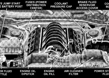
seconds with the accelerator pedal pushed all the way to the floor. Release the accelerator pedal and the key once the engine is running smoothly. Do not overspeed the engine. If the engine shows no sign of starting after two 15- second periods of cranking with the accelerator pedal held to the floor, the “NORMAL STARTING” procedure should be repeated. After Starting The idle speed is controlled automatically and it will decrease as the engine warms up.ENGINE BLOCK HEATER — IF EQUIPPED The engine block heater warms engine coolant and permits quicker starts in cold weather. Connect the cord to a standard 110-115 volt AC electrical outlet with a grounded, three-wire extension cord. The engine block heater cord is routed under the hood on the driver side of the vehicle. It has a removable cap that is located on the driver side of the Integrated Power Module.
WARNING!
Remember to disconnect the cord before driving. Damage to the 110-115 volt electrical cord could cause electrocution.
STARTING AND OPERATING 199
AUTOMATIC TRANSMISSION
CAUTION!
a complete stop.
Damage to the transmission may occur if the follow- ing precautions are not observed: • Shift into PARK only after the vehicle has come to • Shift into or out of REVERSE only after the vehicle has come to a complete stop and the engine is at idle speed. • Do not shift from REVERSE, PARK, or NEUTRAL into any forward gear when the engine is above idle speed. • Before shifting into any gear, make sure your foot
is firmly on the brake pedal.
200 STARTING AND OPERATING
WARNING!
It is dangerous to shift the selector lever out of “P” or “N” if the engine speed is higher than idle speed. If your foot is not firmly on the brake pedal, the vehicle could accelerate quickly forward or in re- verse. You could lose control of the vehicle and hit someone or something. Only shift into gear when the engine is idling normally and when your right foot is firmly on the brake pedal.
Automatic Transmission — General Information The automatic transmission selects individual gears au- tomatically, dependent upon: • Altitude • Vehicle Loading • Driving Style • Selector lever position • Accelerator position • Vehicle speed
The gear shifting process is continuously adapted, de- pendent on the driving style, the driving situation and the road characteristics. NOTE: • After selecting any driving position, wait a moment to allow the gear to engage fully before accelerating, especially when the engine is cold. • If there is a need to restart the engine, be sure to cycle the key to the LOCK position before restarting. Trans- mission engagement may be delayed up to 10 seconds after restart if the key is not cycled to the LOCK position first. • The electronically controlled transmission provides a precise shift schedule. The transmission electronics are self-calibrating. Therefore, the first few shifts on a new vehicle may be somewhat abrupt or soft until after the break-in period. This is a normal condition, and pre- cision shifts will develop within a few shift cycles.
The selector lever is automatically locked while in the P (Park) position. To move the selector lever out of the P (Park) position, the brake pedal must be firmly depressed before the shift lock will release. Shift the selector lever to the desired position only when the engine is idling normally and the brake pedal is applied. Do not release the brake until ready to drive. The vehicle may otherwise accelerate quickly when the selec- tor lever is in D (Drive) or R (Reverse) position.
STARTING AND OPERATING 201
WARNING!
Unintended movement of a vehicle could injure those in and near the vehicle. As with all vehicles, you should never exit a vehicle while the engine is running. Before exiting a vehicle, you should always shift the vehicle into P (Park), remove the key from the ignition, and apply the parking brake. Once the key is removed from the ignition, the transmission selector lever is locked in the P (Park) position, securing the vehicle against unwanted movement. Furthermore, you should never leave children unat- tended inside a vehicle.
Over Temperature Mode The transmission electronics constantly monitor the transmission oil temperature. If the transmission exceeds normal operating temperature, the transmission will change the way it shifts to help control the condition. This may result in a slightly different feeling or response during normal operation in D (Drive) position. After the transmission cools down, it will return to normal opera- tion.
202 STARTING AND OPERATING
Brake/Transmission Shift Interlock System This vehicle is equipped with a brake transmission shift interlock system (BTSI) that holds the selector lever in the P (Park) position when the ignition switch is in the LOCK position. To move the gear selector lever out of the P (Park) position, the ignition switch must be turned to the ON position, and the brake pedal must be depressed.
For electrical system malfunctions, there is an override for the interlock system. In order to override this system the key must be in the ignition with the switch in the ACC or ON positions. Remove the rubber storage tray from the bin located to the right of the shifter lever. The override can be activated by pressing the pink-colored tab, which can be accessed through a hole inside the bin. While the override is pressed, the shifter can be moved out of the park position without pressing the brake. After operation, return the rubber storage tray to its original position.
Brake Interlock Override
5 Speed Automatic Transmission Shifting from D (Drive) to P (Park) or R (Reverse) (or from P or R to D) should be done only after the accelerator pedal is released and the vehicle is stopped. Be sure to keep your foot on the brake when moving the selector lever between these gears.
Gear Ranges
Selector Lever
P (Park) P (Park) supplements the parking brake by locking the transmission. The engine can be started in this range.
STARTING AND OPERATING 203
Never use P (Park) while the vehicle is in motion. Apply the parking brake when leaving the vehicle in this range. When parking on a flat surface, place the gear selector in the P (Park) position first, and then apply the parking brake. When parking on a hill, it is important to set the parking brake before placing the gear selector in P (Park), other- wise the load on the transmission locking mechanism may make it difficult to move the selector out of park. As an added precaution, turn the front wheels toward the curb on a downhill grade and away from the curb on an uphill grade.
WARNING!
Never use Park position on an automatic transmis- sion as a substitute for the parking brake. Always apply parking brake fully when parked to guard against vehicle movement and possible injury or damage.
204 STARTING AND OPERATING
The following indicators should be used to ensure that you have engaged the selector lever into the P (Park) position: • When shifting into P (Park) move the lever all the way • Look at the shift indicator display on the instrument
forward until it stops, and is fully seated.
panel to ensure it is in the P (Park) position.
CAUTION!
Damage to the shifter could result if the selector lever is moved out of P (Park) before the ignition is turned from the LOCK to ON position.
R (Reverse) Shift into R (Reverse) gear only when the vehicle is completely stopped. N (Neutral) No power is transmitted from the engine to the drive axle. When the brakes are released, the vehicle can be moved freely (pushed or towed). Do not engage N
(Neutral) position while driving except to coast when the vehicle is in danger of skidding (e.g., on icy roads). The engine may be started in this range. Use this range for starting your vehicle if it is moving or being towed.
CAUTION!
Coasting the vehicle, or driving for any other reason with selector lever in NEUTRAL can result in trans- mission damage.
WARNING!
Do not coast in N (Neutral) and never turn off the ignition to coast down a hill. These are unsafe practices that limit your response to changing traffic or road conditions. You might lose control of the vehicle and have an accident.
STARTING AND OPERATING 205
Press and hold the selector lever in the “D-” direction and the transmission will shift from the current gear directly to the next lowest gear for best acceleration. NOTE: To avoid overrevving the engine when the selector lever is moved in “D -” direction, the transmis- sion will not shift to a lower gear if the engine’s revolu- tions per minute (RPM) limit would be exceeded. Briefly, press the selector lever in the “D +” direction and the transmission will shift from the current gear to the next higher gear. Press and hold the selector lever in the “D +” direction and the transmission will shift from the current gear directly to gear “D.”
D (Drive) This range should be used for most city and highway driving. It provides the smoothest upshifts and down- shifts and best fuel economy. The transmission automatically upshifts through fifth gear. The D (Drive) position provides optimum driving characteristics under all normal operating conditions. When frequent transmission shifting occurs when using the Overdrive range, such as when operating the vehicle under heavy loading conditions (in hilly terrain, travel- ing into strong head winds, or while towing heavy trailers, use the AutoStick威 mode and select the “3” range. AutoStick威 Gear selection The AutoStick威 feature can be selected by pressing the selector lever to the right or the left with the lever in the D (Drive) position. The gear currently selected is indi- cated in the instrument cluster display. Briefly, press the selector lever in the “D -” direction and the transmission will shift from the current gear to the next lower gear.
206 STARTING AND OPERATING
WARNING!
On slippery road surfaces, never downshift in order to obtain braking action. This could result in drive wheel slip and reduced vehicle control. Your vehi- cle’s ABS will not prevent this type of loss of control. You could lose control of your vehicle and have an accident.
Delayed Shifts in Cold Temperatures During cold temperature operation, you may notice delayed upshifts depending on engine and transmission temperature as well as vehicle speed. This feature im- proves warm up time of the engine and transmission to achieve maximum efficiency. Temporary Transmission Limp Home Mode The transmission is monitored for abnormal conditions. If a condition is detected that could result in transmission damage, the transmission will engage Limp Home Mode. If vehicle acceleration worsens, or the transmission no longer shifts, the transmission is most likely operating in the Limp Home Mode. In this mode, the transmission
will remain in the current gear until the vehicle is brought to a stop. After the vehicle has stopped, P (Park), R (Reverse), and N (Neutral) will continue to operate. Second gear will operate in the D (Drive) shifter position. The Malfunction Indicator Light may be illuminated. A reset feature is available to allow the vehicle to be driven to a dealer for service. To reset the transmission, use the following procedure: 1. Stop the vehicle. 2. Move the selector lever to the P (Park) position. 3. Turn off the engine. 4. Wait approximately 10 seconds. 5. Restart the engine. 6. Move the selector lever to the desired range. If the problem is no longer detected, the transmission will return to normal operation.
NOTE: Even if the transmission can be reset, we recommend that you visit a dealer at your earliest possible convenience. Your dealer has diagnostic equip- ment to determine if the problem could recur. Have the transmission checked at your authorized dealer as soon as possible. If the problem has been momentary, the transmission can be reset to regain all forward gears. Permanent Transmission Limp Home Mode Permanent Limp Home Mode will be activated if the transmission enters temporary Limp Home Mode three times. Follow the reset procedure described under “Tem- porary Transmission Limp Home Mode” in this section. In Permanent Limp Home Mode, P (Park), R (Reverse), and N (Neutral) will continue to operate. Second gear will operate in the D (Drive) shifter position. The mal- function indicator light may illuminate.
STARTING AND OPERATING 207
AUTOSTICK姞 Autostick威 is a driver-interactive transmission that offers manual gear shifting to provide you with more control of the vehicle. Autostick威 allows you to maximize engine braking, eliminate undesirable upshifts and downshifts, and improve overall vehicle performance. This system can also provide you with more control during passing, city driving, cold slippery conditions, mountain driving, trailer towing, and many other situations. Autostick姞 Operation By placing the selector lever in the D (Drive) position, it can be moved from side to side. This allows the driver to select a higher or lower range of gears. Moving the selector lever to the Left (-) triggers a downshift and to the Right (+) an upshift. The gear position will display in the instrument cluster on the transmission range indica- tor. NOTE: • In Autostick威 mode, the transmission will only shift up and down when the driver manually moves the selector lever Right (D+) or Left (D-).
208 STARTING AND OPERATING
• An UPSHIFT message will appear in the Electronic Vehicle Information Center (EVIC) portion of the in- strument cluster when using Autostick威. This message appears in order to alert the driver to upshift to the next gear. The UPSHIFT message will display while operating the vehicle at higher engine revolutions-per- minute (RPM).
You can shift in or out of the Autostick威 mode at any time without taking your foot off the accelerator pedal. When you wish to engage Autostick威, simply move the selector lever to the Right (D+) or Left (D-) while in the D (Drive) position. The transmission will remain in the current gear until an upshift or downshift is chosen. When you wish to disengage Autostick威, hold the selector lever to the right for at least one second. The transmission will now operate automatically, shifting between the five available gears.
gear when coming to a stop.
Autostick姞 General Information • You can start out in first or second gear. The system will ignore attempts to upshift at too low of a vehicle speed. • The transmission will automatically downshift to first • Starting out in second gear is helpful in snowy or icy • Avoid using speed control when Autostick威 is en- • The transmission will not automatically shift up when maximum engine speed is reached while Autostick威 is engaged. • Transmission shifting will be more noticeable when
conditions.
gaged.
Autostick威 is engaged.
DRIVING ON SLIPPERY SURFACES
Acceleration Rapid acceleration on snow covered, wet, or other slip- pery surfaces may cause the rear wheels to pull errati- cally to the right or left. This phenomenon occurs when there is a difference in the surface traction under the rear (driving) wheels.
WARNING!
Rapid acceleration on slippery surfaces is danger- ous. Unequal traction can cause sudden pulling of the rear wheels. You could lose control of the vehicle and possibly have an accident. Accelerate slowly and carefully whenever there is likely to be poor traction (ice, snow, wet mud, loose sand, etc.).
STARTING AND OPERATING 209
Traction When driving on wet or slushy roads, it is possible for a wedge of water to build up between the tire and road surface. This is known as hydroplaning and may cause partial or complete loss of vehicle control and stopping ability. To reduce this possibility, the following precau- tions should be observed: 1. Slow down during rainstorms or when the roads are slushy. 2. Slow down if road has standing water or puddles. 3. Replace tires when tread wear indicators first become visible. 4. Keep tires properly inflated. 5. Maintain sufficient distance between your vehicle and the vehicle in front to avoid a collision in a sudden stop.
210 STARTING AND OPERATING
PARKING BRAKE The parking brake should always be applied when the driver is not in the vehicle.
WARNING!
Never use Park position on an automatic transmis- sion as a substitute for the parking brake. Always apply parking brake fully when parked to guard against vehicle movement and possible injury or damage.
When parking on a flat surface, place the gear selector in the P (Park) position first, and then apply the parking brake. When parking on a hill, it is important to apply the parking brake before placing the gear selector in P (Park), otherwise the load on the transmission locking mecha- nism may make it difficult to move the selector out of park. As an added precaution, turn the front wheels toward the curb on a downhill grade and away from the curb on an uphill grade.
The foot operated parking brake is positioned below the lower left corner of the instrument panel. To apply the parking brake, push the parking brake pedal down and then remove your foot from the pedal. To release the parking brake, push down on the parking brake pedal and then release.
Parking Brake
The brake light in the instrument cluster will turn on when the parking brake is applied and the ignition switch is on.
NOTE: This light only shows that the parking brake is applied. It does not show the degree of brake application.
WARNING!
• Never leave children alone in a vehicle. Leaving children in a vehicle unattended is dangerous for a number of reasons. A child or others could be seriously or fatally injured. Don’t leave the keys in the ignition. A child could operate power windows, other controls, or move the vehicle. • Be sure the parking brake is fully disengaged before driving: failure to do so can lead to brake failure, and an accident.
STARTING AND OPERATING 211
BRAKE SYSTEM
Your vehicle is equipped with dual hydraulic brake systems. If either of the two hydraulic systems loses normal capability, the remaining system will still function. There will be some loss of overall braking effectiveness. This may be evident by increased pedal travel during application, greater pedal force required to slow or stop, and potential activation of the Brake Warning Light. In the event power assist is lost for any reason (for example, repeated brake applications with the engine off) the brakes will still function. The effort required to brake the vehicle will be much greater than that required with the power system operating. Anti-Lock Brake System The Anti-Lock Brake System provides increased vehicle stability and brake performance under most braking con- ditions. The system automatically “pumps” the brakes during severe braking conditions to prevent wheel lock-up. The electronic brake force distribution (EBD) prevents the rear wheels from over-braking and provides greater control of available braking forces applied to the rear axle.
212 STARTING AND OPERATING
When the vehicle is driven over 7 mph (11 km/h), you may also hear a slight clicking sound as well as some related motor noises. These noises are the system per- forming its self check cycle to ensure that the ABS system is working properly. This self check occurs each time the vehicle is started and accelerated past 7 mph (11 km/h). ABS is activated during braking under certain road or stopping conditions. ABS-inducing conditions can in- clude ice, snow, gravel, bumps, railroad tracks, loose debris, or panic stops. You also may experience the following when the brake system goes into Anti-lock: • The ABS motor running (it may continue to run for a • the clicking sound of solenoid valves, • brake pedal pulsations, • and a slight drop or fall away of the brake pedal at the
short time after the stop),
end of the stop.
These are all normal characteristics of ABS.
WARNING!
• The Anti-Lock Brake System contains sophisticated
electronic equipment that may be susceptible to inter- ference caused by improperly installed or high output radio transmitting equipment. This interference can cause possible loss of anti-lock braking capability. In- stallation of such equipment should be performed by qualified professionals.
• Pumping of the Anti-Lock Brakes will diminish their
effectiveness and may lead to an accident. Pumping makes the stopping distance longer. Just press firmly on your brake pedal when you need to slow down or stop.
• Anti-lock system (ABS) cannot prevent the natural laws
of physics from acting on the vehicle, nor can it increase braking or steering efficiency beyond that afforded by the condition of the vehicle brakes and tires or the traction afforded.
• The ABS cannot prevent accidents, including those
resulting from excessive speed in turns, following an- other vehicle too closely, or hydroplaning. Only a safe, attentive, and skillful driver can prevent accidents.
• The capabilities of an ABS equipped vehicle must never
be exploited in a reckless or dangerous manner, which could jeopardize the user’s safety or the safety of others.
All vehicle wheels and tires must be the same size and type and tires must be properly inflated to produce accurate signals for the computer. Anti-Lock Brake Light
The ABS light monitors the Anti-Lock Brake Sys- tem. The light will come on when the ignition switch is turned to the ON position and may stay on for as long as four seconds. If the ABS light remains on or comes on while driving, it indicates that the Anti-Lock portion of the brake system is not functioning and that service is required. However, the conventional brake system will continue to operate normally if the BRAKE warning light is not on. If the ABS light is on, the brake system should be serviced as soon as possible to restore the benefits of Anti-Lock brakes. If the ABS light does not come on when the Ignition switch is turned to the ON position, have the bulb repaired as soon as possible. If both the Brake Warning Light and the ABS Light remain on, the Anti-Lock brakes (ABS) and Electronic
STARTING AND OPERATING 213
Brake Force Distribution (EBD) systems are not function- ing. Immediate repair to the ABS system is required.
POWER STEERING The standard power steering system will give you good vehicle response and increased ease of maneuverability in tight spaces. The system will provide mechanical steering capability if power assist is lost. If for some reason the power assist is interrupted, it will still be possible to steer your vehicle. Under these condi- tions, you will observe a substantial increase in steering effort, especially at very low vehicle speeds and during parking maneuvers. Increased noise levels at the end of the steering NOTE: wheel travel are considered normal and do not indicate that there is a problem with the power steering system. Upon initial start-up in cold weather, the power steering pump may make noise for a short amount of time. This is due to the cold, thick fluid in the steering system. This noise should be considered normal, and does not in any way damage the steering system.
214 STARTING AND OPERATING
WARNING!
Continued operation with reduced power steering assist could pose a safety risk to yourself and others. Service should be obtained as soon as possible.
CAUTION!
Prolonged operation of the steering system at the end of the steering wheel travel will increase the steering fluid temperature and it should be avoided when possible. Damage to the power steering pump may occur.
ELECTRONIC BRAKE CONTROL SYSTEM Your vehicle is equipped with an advanced electronic brake control system commonly referred to as ESP. This system includes the ABS (Anti-Lock Brake System), the TCS (Traction Control System), the BAS (Brake Assist System), and the ESP (Electronic Stability Program). These systems work together to enhance both vehicle stability and control in various driving conditions. ABS (Anti-Lock Brake System) This system aids the driver in maintaining vehicle control under adverse braking conditions by controlling hydrau- lic brake pressure. This prevents wheel lock-up to help avoid skidding on slippery surfaces during braking. For more information about ABS, refer to “Anti-Lock Brake System” in Section 5 of this manual.
WARNING!
The ABS (Anti-Lock Brake System) cannot prevent the natural laws of physics from acting on the vehicle, nor can it increase the traction afforded by prevailing road conditions. The ABS cannot prevent accidents, including those resulting from excessive speed in turns, driving on very slippery surfaces, or hydroplaning. Only a safe, attentive, and skillful driver can prevent accidents. The capabilities of an ABS-equipped vehicle must never be exploited in a reckless or dangerous manner, which could jeopar- dize the user’s safety or the safety of others.
TCS (Traction Control System) This system monitors the amount of wheel spin of each driven wheel. If wheel spin is detected, brake pressure is applied to the slipping wheel(s) and engine power is reduced to provide enhanced acceleration and stability.
STARTING AND OPERATING 215
BAS (Brake Assist System) This system complements the Anti-Lock Brake System (ABS) by optimizing the vehicle braking capability dur- ing emergency braking maneuvers. This system detects an emergency braking situation by sensing the rate and amount of brake application and then applies optimum pressure to the brakes. This can help reduce braking distances. Applying the brakes very quickly results in the best BAS assistance. To receive the benefits of this system, you must apply continuous brake pedal pressure during the stopping sequence. Do not reduce brake pedal pressure unless braking is no longer desired. Once the brake pedal is released, the BAS is deactivated.
216 STARTING AND OPERATING
WARNING!
The BAS (Brake Assist System) cannot prevent the natural laws of physics from acting on the vehicle, nor can it increase the traction afforded by prevail- ing road conditions. The BAS cannot prevent acci- dents, including those resulting from excessive speed in turns, driving on very slippery surfaces, or hydroplaning. Only a safe, attentive, and skillful driver can prevent accidents. The capabilities of a BAS-equipped vehicle must never be exploited in a reckless or dangerous manner, which could jeopar- dize the user’s safety or the safety of others.
ESP (Electronic Stability Program) This system enhances directional control and stability of the vehicle under various driving conditions. The ESP corrects for oversteering and understeering the vehicle by applying the brake of the appropriate wheel. Engine power may also be reduced to assist in counteracting the condition of oversteer or understeer and help the vehicle maintain the desired path.
The ESP uses sensors in the vehicle to determine the path that the driver intends to steer the vehicle and compares it to the actual path of the vehicle. When the actual path does not match the intended path, the ESP applies the brake of the appropriate wheel to assist in counteracting the condition of oversteer or understeer. • Oversteer - when the vehicle is turning more than • Understeer - when the vehicle is turning less than
appropriate for the steering wheel position.
appropriate for the steering wheel position.
The ⬙ESP/TCS Indicator Light,⬙ located in the instrument cluster, starts to flash as soon as the tires lose traction and the ESP system becomes active. The ⬙ESP/TCS Indicator Light⬙ also flashes when TCS is active. If the ⬙ESP/TCS Indicator Light⬙ begins to flash during acceleration, ease up on the accelerator and apply as little throttle as possible. Be sure to adapt your speed and driving to the prevailing road conditions.
WARNING!
The ESP (Electronic Stability Program) cannot pre- vent the natural laws of physics from acting on the vehicle, nor can it increase the traction afforded by prevailing road conditions. The ESP cannot prevent accidents, including those resulting from excessive speed in turns, driving on very slippery surfaces, or hydroplaning. Only a safe, attentive, and skillful driver can prevent accidents. The capabilities of an ESP-equipped vehicle must never be exploited in a reckless or dangerous manner, which could jeopar- dize the user’s safety or the safety of others.
The ESP system has 3 available operating modes: ESP On This is the normal operating mode for the ESP. When- ever the vehicle is started, the ESP system will be in this mode. This mode should be used for most all driving situations. The ESP should only be turned off for specific reasons as noted in the following para- graphs.
STARTING AND OPERATING 217
Partial Off The “Partial Off” mode is intended for times when a more spirited driving experience is desired. It is also intended for driving in deep snow, sand, or gravel. This mode disables the TCS portion of the ESP and raises the threshold for ESP activation, which allows for more wheel spin than what ESP normally allows. The “ESP OFF” button is located in the switch panel above the radio. To enter the “Partial Off” mode, momentarily depress the “ESP OFF” button and the ⬙ESP/TCS Indicator Light⬙ will illuminate. To turn the ESP on again, momen- tarily depress the ⬙ESP OFF⬙ button and the ⬙ESP/TCS Indicator Light⬙ will turn off. NOTE: To improve the vehicle’s traction when driving with snow chains, or when starting-off in deep snow, sand, or gravel, it may be desirable to switch to the “Partial Off” mode by momentarily depressing the “ESP OFF” button. Once the situation requiring “Partial Off” mode is overcome, turn the ESP on again by momentarily depressing the “ESP OFF” button. This may be done while the vehicle is in motion.
218 STARTING AND OPERATING
Full Off This mode is intended for off-highway or off-road use only and should not be used on any public roadways. In this mode, all TCS and ESP stability features are turned off. To enter the “Full Off” mode, depress and hold the “ESP OFF” button for 5 seconds while the vehicle is stopped with the engine running. After 5
seconds, a chime will sound, the ⬙ESP/TCS Indicator Light⬙ will illuminate, and the ⬙ESP OFF⬙ message will display in the vehicle odometer. Press and release the trip odometer button located on the instrument cluster to clear this message. The “ESP OFF” message may appear in the Electronic Vehicle Information Center (EVIC). Refer to “Electronic Vehicle Information Cen- ter (EVIC)” in Section 4 of this manual. To turn ESP on again, momentarily depress the ⬙ESP OFF Button.⬙ NOTE: The ⬙ESP OFF,⬙ or “ESP System Deactivated” message will display and the audible chime will sound when the gear selector is moved into the PARK position from any position other than PARK and then moved out of the PARK position. This will occur when the message was previously cleared.WARNING!
In the ESP Full Off mode, the engine torque reduc- tion and stability features are cancelled. Therefore, the enhanced vehicle stability offered by ESP is unavailable.
NOTE: When the ESP is switched off a feature of the system remains active. This feature controls wheel spin across an axle quite similarly to a limited slip differential. If one wheel on an axle is spinning faster than the other, the system will apply the brake of the spinning wheel and allow more engine torque to be applied to the wheel that is not spinning. To improve the vehicle’s traction when driving with tire chains, or when starting-off in deep snow, sand, or gravel, it may be desirable to switch to the “Partial Off” mode by momentarily depressing the “ESP OFF” button.
WARNING!
With the ESP switched off, the enhanced vehicle stability offered by ESP is unavailable. In an emer- gency evasive maneuver, the ESP system will not engage to assist in maintaining stability. The “Full Off” ESP mode is intended for off-highway or off- road only.
Synchronizing ESP
The malfunction indicator light for the ESP is combined with BAS indicator. If the power supply is interrupted (battery disconnected or discharged), the ESP/BAS malfunction indica- tor light may illuminate with the engine running. If this should occur, turn the steering wheel completely to the left and then to the right. The ESP/BAS malfunction indicator light should go out. However, if the light remains on, have the ESP and BAS checked at your authorized dealer as soon as possible.
STARTING AND OPERATING 219
ESP/BAS Malfunction Indicator Light and ESP/TCS Indicator Light
The malfunction indicator light for the ESP is combined with the BAS indicator. The yellow “ESP/BAS Malfunction Indicator Light” and the yellow “ESP/TCS Indicator Light” in the instrument cluster both come on when the ignition switch is turned to the “ON” position. They should go out with the engine running. The system will turn the “ESP/BAS Malfunction Indica- tor Light” on continuously while the engine running if it detects a malfunction in either the ESP or the BAS or both. If the light remains on after several ignition cycles, and you have driven the vehicle several miles at speeds greater than 30 mph (48 km/h), and the ESP is synchro- nized (refer to Synchronizing ESP), see your authorized dealer as soon as possible to have the problem diagnosed and corrected.
220 STARTING AND OPERATING
NOTE: • ⬙The ⬙ESP/TCS Indicator Light⬙ and the ⬙ESP/BAS Malfunction Indicator Light⬙ will turn on momentarily each time the ignition switch is turned ON. • Each time the ignition is turned ON, the ESP System • The ESP Control System will make buzzing or clicking sounds when it is active. This is normal; the sounds will stop when ESP becomes inactive following the maneuver that caused the ESP activation.
will be ON even if it was turned off previously.
TIRE SAFETY INFORMATION
Tire Markings
STARTING AND OPERATING 221
• Temporary Spare tires are high-pressure compact spares designed for temporary emergency use only. Tires designed to this standard have the letter “T” molded into the sidewall preceding the size designa- tion. Example: T145/80D18 103M. • High Flotation tire sizing is based on U.S. design standards and it begins with the tire diameter molded into the sidewall. Example: 31x10.5 R15 LT.
NOTE: • P (Passenger)-Metric tire sizing is based on U.S. design standards. P-Metric tires have the letter “P” molded into the sidewall preceding the size designation. Ex- ample: P215/65R15 95H. • European Metric tire sizing is based on European design standards. Tires designed to this standard have the tire size molded into the sidewall beginning with the section width. The letter ⬙P⬙ is absent from this tire size designation. Example: 215/65R15 96H • LT (Light Truck)-Metric tire sizing is based on U.S. design standards. The size designation for LT-Metric tires is the same as for P-Metric tires except for the letters “LT” that are molded into the sidewall preced- ing the size designation. Example: LT235/85R16.
222 STARTING AND OPERATING
Tire Sizing Chart
Size Designation:
EXAMPLE:
P = Passenger car tire size based on U.S. design standards ⴖ....blank....ⴖ = Passenger car tire based on European design standards LT = Light Truck tire based on U.S. design standards T = Temporary Spare tire 31 = Overall Diameter in Inches (in) 215 = Section Width in Millimeters (mm) 65 = Aspect Ratio in Percent (%)
—Ratio of section height to section width of tire.
10.5 = Section Width in Inches (in) R = Construction Code
—⬙R⬙ means Radial Construction. —⬙D⬙ means Diagonal or Bias Construction.
15 = Rim Diameter in Inches (in)
STARTING AND OPERATING 223
Service Description:
95 = Load Index
EXAMPLE:
—A numerical code associated with the maximum load a tire can carry.
H = Speed Symbol
—A symbol indicating the range of speeds at which a tire can carry a load corresponding to its load index under certain operating conditions. —The maximum speed corresponding to the Speed Symbol should only be achieved un- der specified operating conditions. (i.e. tire pressure, vehicle loading, road conditions, and posted speed limits).
Load Identification:
ⴖ....blank....ⴖ = Absence of any text on sidewall of the tire indicates a Standard Load (SL) Tire Extra Load (XL) = Extra Load (or Reinforced) Tire Light Load = Light Load Tire C,D,E = Load range associated with the maximum load a tire can carry at a specified pressure
Maximum Load — Maximum Load indicates the maximum load this tire is designed to carry. Maximum Pressure — Maximum Pressure indicates the maximum permissible cold tire inflation pressure for this tire.
224 STARTING AND OPERATING
Tire Identification Number (TIN) The TIN may be found on one or both sides of the tire; however, the date code may only be on one side. Tires with white sidewalls will have the full TIN including date code located on the white sidewall side of the tire.
Look for the TIN on the outboard side of black sidewall tires as mounted on the vehicle. If the TIN is not found on the outboard side then you will find it on the inboard side of the tire.
EXAMPLE:
DOT MA L9 ABCD 0301
DOT = Department of Transportation
—This symbol certifies that the tire is in compliance with the U.S. Department of Transportation tire safety standards, and is approved for highway use.
MA = Code representing the tire manufacturing location. (2 digits) L9 = Code representing the tire size. (2 digits) ABCD = Code used by tire manufacturer. (1 to 4 digits) 03 = Number representing the week in which the tire was manufactured. (2 digits)
—03 means the 3rd week.
01 = Number representing the year in which the tire was manufactured. (2 digits)
—01 means the year 2001. —Prior to July 2000, tire manufacturers were only required to have 1 number to represent the year in which the tire was manufactured. Example: 031 could represent the 3rd week of 1981 or 1991.
Tire Loading and Tire Pressure
Tire and Loading Information Placard
STARTING AND OPERATING 225
Tire Placard Location NOTE: The proper cold tire inflation pressure is listed on either the face of the driver’s door or the driver’s side “B” pillar.
Tire and Loading Information
This placard tells you important information about the: 1) number of people that can be carried in the vehicle 2) the total weight your vehicle can carry 3) the tire size designed for your vehicle 4) the cold tire inflation pressures for the front, rear and spare tires.
Tire Placard Location
226 STARTING AND OPERATING
Loading The vehicle maximum load on the tire must not exceed the load carrying capacity of the tire on your vehicle. You will not exceed the tire’s load carrying capacity if you adhere to the loading conditions, tire size, and cold tire inflation pressures specified on the “Tire and Loading Information” placard and in the “Vehicle Loading” sec- tion of this manual. NOTE: Under a maximum loaded vehicle condition, gross axle weight ratings (GAWR’s) for the front and rear axles must not be exceeded. For further information on GAWR’s, vehicle loading, and trailer towing, refer to the “Vehicle Loading” section of this manual. To determine the maximum loading conditions of your vehicle, locate the statement “The combined weight of occupants and cargo should never exceed XXX kg or XXX lbs.” on the Tire and Loading Information placard. The combined weight of occupants, cargo/luggage and trailer tongue weight (if applicable) should never exceed the weight referenced here.
Steps for Determining Correct Load Limit 1. Locate the statement “The combined weight of occu- pants and cargo should never exceed XXX pounds” on your vehicle’s placard. 2. Determine the combined weight of the driver and passengers that will be riding in your vehicle. 3. Subtract the combined weight of the driver and pas- sengers from XXX kilograms or XXX pounds. 4. The resulting figure equals the available amount of cargo and luggage load capacity. For example, if “XXX” amount equals 1400 lbs. and there will be five 150 lb. passengers in your vehicle, the amount of available cargo and luggage load capacity is 650 lbs. (since 5 x 150 = 750, and 1400 – 750 = 650 lbs.) 5. Determine the combined weight of luggage and cargo being loaded on the vehicle. That weight may not safely exceed the available cargo and luggage load capacity calculated in Step 4. 6. If your vehicle will be towing a trailer, load from your trailer will be transferred to your vehicle. Consult this
manual to determine how this reduces the available cargo and luggage load capacity of your vehicle. NOTE: The following table shows examples on how to calculate total load, cargo/luggage, and towing capaci- ties of your vehicle with varying seating configurations and number and size of occupants. This table is for
STARTING AND OPERATING 227
illustration purposes only and may not be accurate for the seating and load carry capacity of your vehicle. the combined NOTE: weight of occupants and cargo should never exceed 865
lbs. (392 Kg).For the following example,
228 STARTING AND OPERATING
WARNING!
1. Safety—
STARTING AND OPERATING 229
Overloading of your tires is dangerous. Overloading can cause tire failure, affect vehicle handling, and increase your stopping distance. Use tires of the recommended load capacity for your vehicle. Never overload them.
TIRES — GENERAL INFORMATION
Tire Pressure Proper tire inflation pressure is essential to the safe and satisfactory operation of your vehicle. Three primary areas are affected by improper tire pressure:
WARNING!
• Improperly inflated tires are dangerous and can cause accidents. • Under inflation increases tire flexing and can result in tire failure. • Over inflation reduces a tire’s ability to cushion shock. Objects on the road and chuckholes can cause damage that result in tire failure. • Unequal tire pressures can cause steering prob- lems. You could lose control of your vehicle. • Over inflated or under inflated tires can affect vehicle handling and can fail suddenly, resulting in loss of vehicle control. • Unequal tire pressures from one side of the vehicle to the other can cause the vehicle to drift to the right or left. • Always drive with each tire inflated to the recom- mended cold tire inflation pressure.
230 STARTING AND OPERATING
2. Economy— Improper inflation pressures can cause uneven wear patterns to develop across the tire tread. These abnormal wear patterns will reduce tread life resulting in a need for earlier tire replacement. Under inflation, also increases tire rolling resistance and results in higher fuel consump- tion. 3. Ride Comfort and Vehicle Stability— Proper tire inflation contributes to a comfortable ride. Over inflation produces a jarring and uncomfortable ride. Tire Inflation Pressures The proper cold tire inflation pressure is listed either on the face of the driver’s door or on the driver’s side “B” pillar. Some vehicles may have Supplemental Tire Pressure Information for vehicle loads that are less than the maximum loaded vehicle condition. These pressure con- ditions will be found in the “Supplemental Tire Pressure Information” section of this manual.
Tire Placard Location
The pressure should be checked and adjusted as well as inspecting for signs of tire wear or visible damage at least once a month. Use a good quality pocket-type gauge to check tire pressure. Do not make a visual judgement when determining proper inflation. Radial tires may look properly inflated even when they are under inflated.
CAUTION!
After inspecting or adjusting the tire pressure, al- ways reinstall the valve stem cap (if equipped). This will prevent moisture and dirt from entering the valve stem, which could damage the valve stem.
Inflation pressures specified on the placard are always “cold tire inflation pressure.” Cold tire inflation pressure is defined as the tire pressure after the vehicle has not been driven for at least 3 hours, or driven less than 1 mile (1 km) after a 3 hour period. The cold tire inflation pressure must not exceed the maximum inflation pres- sure molded into the tire sidewall. Check tire pressures more often if subject to a wide range of outdoor temperatures, as tire pressures vary with temperature changes. Tire pressures change by approximately 1 psi (7 kPa) per 12° F (7° C) of air temperature change. Keep this in mind when checking tire pressure inside a garage, especially in the winter.
STARTING AND OPERATING 231
Example: If garage temperature = 68° F (20° C) and the outside temperature = 32° F (0° C) then the cold tire inflation pressure should be increased by 3 psi (21 kPa), which equals 1 psi (7 kPa) for every 12° F (7° C) for this outside temperature condition. Tire pressure may increase from 2 to 6 psi (13 to 40 kPa) during operation. DO NOT reduce this normal pressure build up or your tire pressure will be too low. Tire Pressures for High Speed Operation The manufacturer advocates driving at safe speeds within posted speed limits. Where speed limits or condi- tions are such that the vehicle can be driven at high speeds, maintaining correct tire inflation pressure is very important. Increased tire pressure and reduced vehicle loading may be required for high-speed vehicle opera- tion. Refer to original equipment or an authorized tire dealer for recommended safe operating speeds, loading and cold tire inflation pressures.
232 STARTING AND OPERATING
WARNING!
High speed driving with your vehicle under maxi- mum load is dangerous. The added strain on your tires could cause them to fail. You could have a serious accident. Don’t drive a vehicle loaded to the maximum capacity at continuous speeds above 75
mph (120 km/h).Radial-Ply Tires
WARNING!
Combining radial ply tires with other types of tires on your vehicle will cause your vehicle to handle poorly. The instability could cause an accident. Al- ways use radial ply tires in sets of four (or 6, in case of trucks with dual rear wheels). Never combine them with other types of tires.
Cuts and punctures in radial tires are repairable only in the tread area because of sidewall flexing. Consult your authorized tire dealer for radial tire repairs. Tire Spinning When stuck in mud, sand, snow, or ice conditions, do not spin your vehicle’s wheels above 35 mph (55 km/h). Refer to the paragraph on “Freeing A Stuck Vehicle” in Section 6 of this manual.
WARNING!
Fast spinning tires can be dangerous. Forces gener- ated by excessive wheel speeds may cause tire dam- age or failure. A tire could explode and injure someone. Do not spin your vehicle’s wheels faster than 30 mph (48 km/h) for more than 30 seconds continuously when you are stuck, and don’t let anyone near a spinning wheel, no matter what the speed.
Tread Wear Indicators Tread wear indicators are in the original equipment tires to help you in determining when your tires should be replaced.
These indicators are molded into the bottom of the tread grooves. They will appear as bands when the tread depth becomes 1/16 inch (2 mm). When the tread is worn to the tread wear indicators, the tire should be replaced. Many states have laws requiring tire replacement at this point.
STARTING AND OPERATING 233
Life of Tire The service life of a tire is dependent upon varying factors including but not limited to: • Driving style • Tire pressure • Distance driven
WARNING!
Tires and spare tire should be replaced after six years, regardless of the remaining tread. Failure to follow this warning can result in sudden tire failure. You could lose control and have an accident result- ing in serious injury or death.
Keep dismounted tires in a cool, dry place with as little exposure to light as possible. Protect tires from contact with oil, grease, and gasoline.
234 STARTING AND OPERATING
Replacement Tires The tires on your new vehicle provide a balance of many characteristics. They should be inspected regularly for wear and correct cold tire inflation pressure. The manu- facturer strongly recommends that you use tires equiva- lent to the originals in size, quality and performance when replacement is needed (refer to the paragraph on “Tread Wear Indicators”). Refer to the “Tire and Loading Information” placard for the size designation of your tire. The service description and load identification will be found on the original equipment tire. Failure to use equivalent replacement tires may adversely affect the safety, handling, and ride of your vehicle. We recommend that you contact your original equipment or an autho- rized tire dealer with any questions you may have on tire specifications or capability.
WARNING!
• Do not use a tire, wheel size or rating other than that specified for your vehicle. Some combina- tions of unapproved tires and wheels may change suspension dimensions and performance charac- teristics, resulting in changes to steering, han- dling, and braking of your vehicle. This can cause unpredictable handling and stress to steering and suspension components. You could lose control and have an accident resulting in serious injury or death. Use only the tire and wheel sizes with load ratings approved for your vehicle. • Never use a tire with a smaller load index or capacity, other than what was originally equipped on your vehicle. Using a tire with a smaller load index could result in tire overloading and failure. You could lose control and have an accident. • Failure to equip your vehicle with tires having adequate speed capability can result in sudden tire failure and loss of vehicle control.
CAUTION!
Replacing original tires with tires of a different size may result in false speedometer and odometer read- ings.
Alignment And Balance Poor suspension alignment may result in: • Fast tire wear. • Uneven tire wear, such as feathering and one-sided • Vehicle pull to right or left.
wear.
STARTING AND OPERATING 235
Tires may also cause the vehicle to pull to the left or right. Alignment will not correct this condition. See your dealer for proper diagnosis. Improper alignment will not cause vehicle vibration. Vibration may be a result of tire and wheel out-of- balance. Proper balancing will reduce vibration and avoid tire cupping and spotty wear.
TIRE CHAINS If driving conditions require tire chains for your vehicle, use only chains that meet SAE type “Class S” specifica- tions. In addition, only install tire chains on 245/45ZR20
size tires. Contact you local dealership or tire dealer for these size tires.236 STARTING AND OPERATING
CAUTION!
To avoid damage to your vehicle or tires, observe the following precautions: • Because of restricted chain clearance between tires and other suspension components, it is important that only chains in good condition are used. Broken chains can cause serious damage. Stop the vehicle immediately if noise occurs that could indicate chain breakage. Remove the damaged parts of the chain before further use. • Install chains on the rear wheels as tightly as pos- sible and then retighten after driving about 1⁄2 mile (0.8 km).
• Do not exceed 30 mph (48 km/h). • Drive cautiously and avoid severe turns and large • Use on Rear Wheels only. • Do not drive for prolonged period on dry pavement. • Observe the tire chain manufacturer’s instructions on the method of installation, operating speed, and conditions for use. Always use the lower suggested operating speed of the chain manufacturer if differ- ent from the speed recommended by the manufac- ture.
bumps, especially with a loaded vehicle.
In order to avoid damage to tires, chains, and NOTE: your vehicle do not drive for a prolonged period of time on dry pavement. Observe the tire chain manufacturer’s instructions on method of installation, operating speed, and conditions for usage. Always use the lower suggested operating speed if both the chain manufacturer and vehicle manufacture suggest a maximum speed. This notice applies to all chain traction devices, including link and cable (radial) chains.
SNOW TIRES Some areas of the country require the use of snow tires during winter. Standard tires are of the all season type and satisfy this requirement as indicated by the M+S designation on the tire sidewall. If you need snow tires, select tires equivalent in size and type to the original equipment tires. Use snow tires only in sets of 4, failure to do so may adversely affect the safety and handling of your vehicle.
Snow tires generally have lower speed ratings than what was originally equipped with your vehicle and should not be operated at sustained speeds over 75 mph (120
km/h).TIRE ROTATION RECOMMENDATIONS Tires on the front and rear axles of vehicles operate at different loads and perform different steering, driving, and braking functions. For these reasons, they wear at unequal rates, and tend to develop irregular wear pat- terns.
STARTING AND OPERATING 237
These effects can be reduced by timely rotation of tires. The benefits of rotation are especially worthwhile with aggressive tread designs such as those on all season type tires. Rotation will increase tread life, help to maintain mud, snow, and wet traction levels, and contribute to a smooth, quiet ride. Follow the “Maintenance Schedules” in Section 8 of this manual for the recommended tire rotation frequency for your type of driving. Remember, more frequent rotation is permissible if desired. Also, correct for anything caus- ing rapid or unusual wear prior to performing the tire rotation.
238 STARTING AND OPERATING
Tire Rotation — Standard Tires The suggested rotation method is the “side-to-side” as shown in the following diagram.
Tire Rotation — All Season Tires The suggested rotation method for vehicles equipped with all season tires is the “forward-cross” as shown in the following diagram.
TIRE PRESSURE MONITOR SYSTEM (TPMS) — IF EQUIPPED • The Tire Pressure Monitor System (TPMS) will warn the driver of a low tire pressure based on the vehicle recommended cold placard pressure. • The tire pressure will vary with temperature by about 1 psi (6.9 kPa) for every 12°F (6.5°C). This means that when the outside temperature decreases, the tire pres- sure will decrease. Tire pressure should always be set based on cold inflation tire pressure. This is defined as the tire pressure after the vehicle has not been driven for at least 3 hours, or driven less than 1 mile (1 km) after a 3 hour period. The cold tire inflation pressure must not exceed the maximum inflation pressure molded into the tire sidewall. Refer to the “Tires – General Information” in this section for information on how to properly inflate the vehicle’s tires. The tire pressure will also increase as the vehicle is driven - this is normal and there should be no adjustment for this increased pressure.
STARTING AND OPERATING 239
• The TPM System will warn the driver of a low tire pressure if the tire pressure falls below the low- pressure warning limit for any reason, including low temperature effects. • The TPM System will continue to warn the driver of low tire pressure as long as the condition exists, and will not turn off until the tire pressure is at or above the recommended cold placard pressure. Once the low tire pressure warning (Tire Pressure Monitoring Tell- tale Light) illuminates, you must increase the tire pressure to the recommended cold placard pressure in order for the Tire Pressure Monitoring Telltale Light to turn off. The system will automatically update and the Tire Pressure Monitoring Telltale Light will turn off once the system receives the updated tire pressures. The vehicle may need to be driven for up to 10 minutes above 15 mph (25 km/h) in order for the TPMS to receive this information.
240 STARTING AND OPERATING
− For example, your vehicle may have a recom- mended cold (parked for more than 3 hours) placard pressure of 30 psi (207 kPa). If the ambient tempera- ture is 68°F (20°C) and the measured tire pressure is 27 psi (186 kPa), a temperature drop to 20°F (-7°C) will decrease the tire pressure to approximately 23
psi (157 kPa). This tire pressure is sufficiently low enough to turn ON the Tire Pressure Monitoring Telltale light. Driving the vehicle may cause the tire pressure to rise to approximately 27 psi (186 kPa), but the Tire Pressure Monitoring Telltale Light will still be ON. In this situation, the Tire Pressure Monitoring Telltale Light will turn OFF only after the tires are inflated to the vehicle’s recommended cold placard pressure value.NOTE: Seasonal temperature changes will affect tire pressure, and the TPMS will monitor the actual tire pressure in the tire.
CAUTION!
• The TPMS has been optimized for the original equipment tires and wheels. TPMS pressures and warning have been established for the tire size equipped on your vehicle. Undesirable system operation or sensor damage may result when using replacement equipment that is not of the same size, type, and/or style. After-market wheels can cause sensor damage. Do not use tire sealant from a can, or balance beads if your vehicle is equipped with a TPMS, as damage to the sensors may result. • After inspecting or adjusting the tire pressure, always reinstall the valve stem cap. This will prevent moisture and dirt from entering the valve stem, which could damage the Tire Pressure Monitoring Sensor.
while adjusting your tire pressure.
NOTE: • The TPMS is not intended to replace normal tire care and maintenance, or to provide warning of a tire failure or condition. • The TPMS should not be used as a tire pressure gauge • Driving on a significantly under-inflated tire causes the tire to overheat and can lead to tire failure. Under-inflation also reduces fuel efficiency and tire tread life, and may affect the vehicle’s handling and stopping ability. • The TPMS is not a substitute for proper tire mainte- nance, and it is the driver’s responsibility to maintain correct tire pressure, even if under-inflation has not reached the level to trigger illumination of the Tire Pressure Monitoring Telltale light.
Base System — If Equipped The Tire Pressure Monitor System (TPMS) uses wireless technology with wheel rim mounted electronic sensors to
STARTING AND OPERATING 241
monitor tire pressure levels. Sensors, mounted to each wheel as part of the valve stem, transmit tire pressure readings to the Receiver Module. It is particularly important for you to check the NOTE: tire pressure in all of the tires on your vehicle regularly and to maintain the proper pressure. The TPMS consists of the following components: • Receiver Module • 4 Tire Pressure Monitoring Sensors • Tire Pressure Monitoring Telltale Light Tire Pressure Monitoring Low Pressure Warnings
The Tire Pressure Monitoring Telltale Light will illuminate in the instrument cluster and an audible chime will sound when tire pressure is low in one or more of the four active road tires. The audible chime will sound once every ignition cycle for each condition that it detects. Should this occur, you should stop as soon as possible, check the inflation pressure of each tire on your vehicle, and inflate each tire to the vehicle’s recom- mended cold placard pressure value. Once the system
242 STARTING AND OPERATING
receives the updated tire pressures, the system will automatically update and the Tire Pressure Monitoring Telltale Light will turn off. The vehicle may need to be driven for up to 10 minutes above 15 mph (25 km/h) in order for the TPMS to receive this information. Low pressure in the spare tire will not cause the Tire Pressure Monitoring Telltale Light to illuminate or the chime to sound. NOTE: The compact spare tire (if so equipped) does not have a tire pressure monitoring sensor. Therefore, the TPMS will not monitor the pressure in the compact spare tire. However, if you install the compact spare tire in place of a road tire that has a pressure below the low-pressure warning limit, the Tire Pressure Monitoring Telltale Light will remain ON and a chime will still sound each ignition key cycle. Once you repair or replace the original road tire, and reinstall it on the vehicle in place of the compact spare, the TPMS will update automatically and the Tire Pressure Monitoring Telltale Light will turn OFF, as long no tire pressure is below the low-pressure warning limit in any of the four active road tires. The
vehicle may need to be driven for up to 10 minutes above 15 mph (25 km/h) in order for the TPMS to receive this information. Check TPMS Warning The Tire Pressure Monitoring Telltale Light will flash on and off for 60 seconds and an audible chime will sound when a system fault is detected. The flash cycle will repeat every ten minutes, without an audible chime, until the fault condition no longer exists. If the ignition key is cycled, this sequence will repeat, providing the system fault still exists. Premium System — If Equipped The Tire Pressure Monitor System (TPMS) uses wireless technology with wheel rim mounted electronic sensors to monitor tire pressure levels. Sensors, mounted to each wheel as part of the valve stem, transmit tire pressure readings to the Receiver Module. It is particularly important for you to check the NOTE: tire pressure in all of the tires on your vehicle regularly and to maintain the proper pressure.
STARTING AND OPERATING 243
values flashing. Should this occur, you should stop as soon as possible, and inflate the tires with low pressure (those flashing in the EVIC graphic) to the vehicle’s recommended cold placard pressure value. Once the system receives the updated tire pressures, the system will automatically update, the graphic display in the EVIC will stop flashing, and the Tire Pressure Monitoring Telltale Light will turn off. The vehicle may need to be driven for up to 10 minutes above 15 mph (25 km/h) in order for the TPMS to receive this information. Low pressure in the spare tire will not cause the Tire Pressure Monitoring Telltale Light to illuminate or the chime to sound.
The TPMS consists of the following components: • Receiver Module • 4 Tire Pressure Monitoring Sensors • 3 Trigger Modules (mounted in three of the four • Various Tire Pressure Monitoring System Messages, which display in the Electronic Vehicle Information Center (EVIC)
wheel-wells)
• Tire Pressure Monitoring Telltale Light Tire Pressure Monitoring Low Pressure Warnings
The Tire Pressure Monitoring Telltale Light will illuminate in the instrument cluster and an audible chime will sound when tire pressure is low in one or more of the four active road tires. The audible chime will sound once every ignition cycle for each condition that it detects. In addition, the Electronic Vehicle Infor- mation Center (EVIC) will display one or more Low Pressure messages (Left Front, Left Rear, Right Front, Right Rear) for 3 seconds and a graphic showing the pressure values of each tire with the low tire pressure
244 STARTING AND OPERATING
NOTE: • You can change the pressure units to display in PSI, kPA, or BAR. Refer to “Language,” under “Personal Settings (Customer Programmable Features),” under “Electronic Vehicle Information Center (EVIC)” in Section 4 of this manual for details. • The compact spare tire (if so equipped) does not have a tire pressure monitoring sensor. Therefore, the TPMS will not monitor the pressure in the compact spare tire. However, if you install the compact spare tire in place
of a road tire that has a pressure below the low- pressure warning limit, the Tire Pressure Monitoring Telltale Light will remain ON and a chime will still sound each ignition key cycle. In addition, the EVIC will still display a low-pressure message and a flash- ing pressure value in the graphic display. Once you repair or replace the original road tire, and reinstall it on the vehicle in place of the compact spare, the TPMS will update automatically. In addition, the Tire Pres- sure Monitoring Telltale Light will turn OFF, and the graphic in the EVIC will stop flashing and display a new pressure value, as long no tire pressure is below the low-pressure warning limit in any of the four active road tires. The vehicle may need to be driven for up to 10 minutes above 15 mph (25 km/h) in order for the TPMS to receive this information.
Check TPMS Warning The Tire Pressure Monitoring Telltale Light will flash on and off for 60 seconds and an audible chime will sound when a system fault is detected. The flash cycle will repeat every ten minutes, without an audible chime, until the fault condition no longer exists. In addition to the telltale and chime, the Electronic Vehicle Information
Center (EVIC) will display a ⬙CHECK TPM SYSTEM⬙ message for 3 seconds when a system fault is detected. In the event that a fault occurs because the system did not receive a pressure value from one or more Tire Pressure Monitoring Sensors, the EVIC will display the ⬙CHECK TPM SYSTEM⬙ message and then display dashes (- -) in place of the pressure value to indicate which sensor is not being received.
STARTING AND OPERATING 245
NOTE: You can change the pressure units to display in PSI, kPA, or BAR. Refer to “Language,” under “Personal Settings (Customer Programmable Features),” under “Electronic Vehicle Information Center (EVIC)” in Sec- tion 4 of this manual for details. If the ignition key is cycled, this sequence will repeat, providing the system fault still exists. If the system fault no longer exists, the Tire Pressure Monitoring Telltale Light will no longer flash, and the ⬙CHECK TPM SYS- TEM⬙ message will no longer display, and a pressure value will display in place of the dashes. General Information This device complies with part 15 of the FCC rules and RSS 210 of Industry Canada. Operation is subject to the following conditions: • This device may not cause harmful interference. • This device must accept any interference received, including interference that may cause undesired op- eration.
246 STARTING AND OPERATING
The tire pressure sensors are covered under one of the following licenses:
United States . . . . . . . . . . . . . . . . . . . . . KR5S120123
Canada . . . . . . . . . . . . . . . . . . . . . . . . 2671-S120123FUEL REQUIREMENTS
6.1L Engine
The 6.1L engine is designed to meet all emissions regulations and provide excel- lent fuel economy and performance when using high-quality premium unleaded gasoline with an octane rating of 91 or higher.
Light spark knock at low engine speeds is not harmful to your engine. However, continued heavy spark knock at high speeds can cause damage and immediate service is required. Poor quality gasoline can cause problems such as hard starting, stalling, and hesitations. If you experience these symptoms, try another brand of “premium” gasoline before considering service for the vehicle.
Over 40 automobile manufacturers around the world have issued and endorsed consistent gasoline specifica- tions (the World Wide Fuel Charter, WWFC) which define fuel properties necessary to deliver enhanced emissions, engine performance, and durability for your vehicle. The manufacturer recommends the use of gaso- lines that meet the WWFC specifications if they are available. Reformulated Gasoline Many areas of the country require the use of cleaner burning gasoline referred to as “Reformulated Gasoline”. Reformulated gasolines contain oxygenates, and are spe- cifically blended to reduce vehicle emissions and im- prove air quality. The manufacturer supports the use of reformulated gaso- lines. Properly blended reformulated gasolines will pro- vide excellent performance and durability of engine and fuel system components.
Gasoline/Oxygenate Blends Some fuel suppliers blend unleaded gasoline with oxy- genates such as 10% ethanol, MTBE, and ETBE. Oxygen- ates are required in some areas of the country during the winter months to reduce carbon monoxide emissions. Fuels blended with these oxygenates may be used in your vehicle.
CAUTION!
DO NOT use gasolines containing Methanol or E85
Ethanol. Use of these blends may result in starting and driveability problems and may damage critical fuel system components.Problems that result from using methanol/gasoline or E85 Ethanol blends are not the responsibility of the manufacturer. While MTBE is an oxygenate made from Methanol, it does not have the negative effects of Metha- nol.
STARTING AND OPERATING 247
MMT In Gasoline MMT is a manganese containing metallic additive that is blended into some gasoline to increase the octane num- ber. Gasolines blended with MMT offer no performance advantage beyond gasolines of the same octane number without MMT. Gasolines blended with MMT have shown to reduce spark plug life and reduce emission system performance in some vehicles. The manufacturer recom- mends using gasolines without MMT. Since the MMT content of gasoline may not be indicated on the pump, you should ask your gasoline retailer if his/her gasoline contains MMT. It is even more important to look for gasolines without MMT in Canada, because MMT can be used at levels higher than allowed in the United States. MMT is pro- hibited in Federal and California reformulated gasolines. Materials Added to Fuel All gasoline sold in the United States is required to contain effective detergent additives. Use of additional detergents or other additives are not needed under
248 STARTING AND OPERATING
normal conditions and they would result in additional cost. Therefore, you should not have to add anything to the fuel. Fuel System Cautions
CAUTION!
Follow these guidelines to maintain your vehicle’s performance: • The use of leaded gas is prohibited by Federal law. Using leaded gasoline can impair engine performance, or damage the emission control system. • An out-of-tune engine, or certain fuel or ignition malfunctions, can cause the catalytic converter to overheat. If you notice a pungent burning odor or some light smoke, your engine may be out-of-tune or malfunctioning and may require immediate service. Contact your dealer for service assistance. • The use of fuel additives, which are now being sold as octane enhancers, are not recommended. Most of these
products contain high concentrations of methanol. Fuel system damage or vehicle performance problems resulting from the use of such fuels or additives are not the responsibility of the manufacturer.
Intentional tampering with emissions control in civil penalties being assessed
NOTE: systems can result against you. Carbon Monoxide Warnings
WARNING!
Carbon monoxide (CO) in exhaust gases is deadly. Follow the precautions below to prevent carbon monoxide poisoning: • Do not inhale exhaust gases. They contain carbon monoxide, a colorless and odorless gas, which can kill. Never run the engine in a closed area, such as a garage, and never sit in a parked vehicle with the engine running for an extended period. If the vehicle is stopped in an open area with the engine running for
more than a short period, adjust the ventilation system to force fresh, outside air into the vehicle. • Guard against carbon monoxide with proper mainte- nance. Have the exhaust system inspected every time the vehicle is raised. Have any abnormal conditions repaired promptly. Until repaired, drive with all side windows fully open. • Keep the trunk closed when driving your vehicle to prevent carbon monoxide and other poisonous ex- haust gases from entering the vehicle.
STARTING AND OPERATING 249
ADDING FUEL
Fuel Filler Cap (Gas Cap) The gas cap is located behind the fuel filler door on the left side of the vehicle. Push in on the left side (near the edge) of the fuel filler door to access the fuel filler cap. If the gas cap is lost or damaged, be sure the replacement cap is for use with this vehicle.
Fuel Filler Door
250 STARTING AND OPERATING
NOTE: When removing the fuel filler cap, lay the cap tether in the hook, located on the fuel filler cap door reinforcement.
Gas Cap Tether Hook
CAUTION!
the fuel system.
• Damage to the fuel system or emission control system could result from using an improper fuel tank filler tube cap (gas cap). • A poorly fitting gas cap could let impurities into • A poorly fitting gas cap may cause the Malfunc- • To avoid fuel spillage and overfilling, do not “top off” the fuel tank after filling. When the fuel nozzle “clicks” or shuts off, the fuel tank is full.
tion Indicator Light to turn on.
STARTING AND OPERATING 251
Loose Fuel Filler Cap Message If the vehicle diagnostic system determines that the fuel filler cap is loose, improperly installed, or damaged, a “Check Gascap” message will display in the Electronic Vehicle Information Center (EVIC). If this occurs, tighten the fuel filler cap properly and press the odometer reset button to turn off the message. If the problem continues, the message will appear the next time the vehicle is started. A loose, improperly installed, or damaged fuel filler cap may also turn on the Malfunction Indicator Light (MIL). Refer to “Onboard Diagnostic System” in Section 7 of this manual for more information.
WARNING!
• Never have any smoking materials lit in or near the vehicle when the gas cap is removed or the tank filled. • Never add fuel to the vehicle when the engine is • A fire may result if gasoline is pumped into a portable container that is inside of a vehicle. You could be burned. Always place gas containers on the ground while filling.
running.
NOTE: • Tighten the gas cap until you hear a “clicking” sound. This is an indication that the gas cap is tightened properly. The Malfunction Indicator Light in the in- strument cluster may turn on if the gas cap is not secured properly. Make sure that the gas cap is tight- ened each time the vehicle is refueled. • When the fuel nozzle “clicks” or shuts off, the fuel
tank is full.
252 STARTING AND OPERATING
VEHICLE LOADING The load carrying capacity of your vehicle is shown on the “Vehicle Certification Label.” This information should be used for passenger and luggage loading as indicated. If the seatbacks are folded for carrying cargo, do not exceed the specified GVWR and GAWR. Vehicle Certification Label Your vehicle has a certification label attached to the rear of the driver’s door. The label contains the following information: • Name of manufacturer • Month and year of manufacture • Gross Vehicle Weight Rating (GVWR) • Gross Axle Weight Rating (GAWR) front • Gross Axle Weight Rating (GAWR) rear • Vehicle Identification Number (VIN) • Type of Vehicle
• Month Day and Hour of Manufacture (MDH) The bar code allows a computer scanner to read the Vehicle Identification Number (VIN). Gross Vehicle Weight Rating (GVWR) The GVWR is the total allowable weight of your vehicle. This includes driver, passengers, and cargo. The total load must be limited so that you do not exceed the GVWR. Gross Axle Weight Rating (GAWR) The GAWR is the maximum capacity of the front and rear axles. Distribute the load over the front and rear axles evenly. Make sure that you do not exceed either front or rear GAWR.
WARNING!
Because the front wheels steer the vehicle, it is important that you do not exceed the maximum front or rear GAWR. A dangerous driving condition can result if either rating is exceeded. You could lose control of the vehicle and have an accident.
STARTING AND OPERATING 253
driving. If weighing the loaded vehicle shows that you have exceeded either GAWR, but the total load is within the specified GVWR, you must redistribute the weight. Improper weight distribution can have an adverse effect on the way your vehicle steers and handles and the way the brakes operate. A loaded vehicle is shown in the illustration. Note that neither the GVWR nor the GAWR capacities have been exceeded.
Overloading The load carrying components (axle, springs, tires, wheels, etc.) of your vehicle will provide satisfactory service as long as you do not exceed the GVWR and front and rear GAWR. The best way to figure out the total weight of your vehicle is to weigh it when it is fully loaded and ready for operation. Weigh it on a commercial scale to insure that it is not over the GVWR. Figure out the weight on the front and rear of the vehicle separately. It is important that you distribute the load evenly over the front and rear axles. Overloading can cause potential safety hazards and shorten useful service life. Heavier axles or suspension components do not necessarily increase the vehicle’s GVWR. Loading To load your vehicle properly, first figure out its empty weight, axle by axle and side by side. Store heavier items down low and be sure you distribute their weight as evenly as possible. Stow all loose items securely before
254 STARTING AND OPERATING
EXAMPLE ONLY
Empty Weight
Load (Including driver, pas- sengers, and cargo) Total
GAWR
Front Axle 2054 lbs (932 kg) 271 lbs (123 kg) 2325 lbs (1055 kg) 2546 lbs (1155 kg)
Rear Axle
1805 lbs (819 kg ) 579 lbs (263 kg) 2384 lbs (1081 kg) 2708 lbs (1228 kg)
NOTE: Refer to the “Vehicle Certification Label” at- tached to the rear of the driver’s door for your vehicle’s GVWR and GAWRs. This table is only an example.
TRAILER TOWING Trailer towing with this vehicle is not recommended. RECREATIONAL TOWING (BEHIND MOTORHOME, ETC.) TOWING THIS VEHICLE BEHIND ANOTHER VEHICLE (Flat towing with all four wheels on the ground) Recreational towing for this vehicle is not recommended. If the vehicle requires towing, make sure all NOTE: four wheels are off the ground. GROUND CLEARANCE
CAUTION!
Damage to the front and rear fascias can occur if you disregard the low ground clearance in the front and rear of this vehicle. Pay close attention when parking to avoid running into parking curbs. Exercise caution when entering or exiting steep driveways or when pulling off the road onto soft shoulders.
WHAT TO DO IN EMERGENCIES
CONTENTS
䡵 Hazard Warning Flasher . . . . . . . . . . . . . . . . . 256
䡵 If Your Engine Overheats . . . . . . . . . . . . . . . . 256
䡵 TIREFIT Tire Repair . . . . . . . . . . . . . . . . . . . . 257
䡵 Jump-Starting Procedures . . . . . . . . . . . . . . . . 262