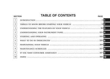
- Download PDF Manual
-
Console Features The center console contains a large storage bin. The storage bin contains a four-slot coin holder (designed to hold various size coins) and a rubber mat at the bottom of the bin for noise control. The bin is large enough to hold a portable AC/DC converter to power laptops, games, or other electrical equipment. Two slots at the top right side of the bin provide clearance for power cords to pass conveniently out of the bin with the lid closed. This feature is ideal for games, laptops, cell phones, or other electrical equipment. The console’s front-opening lid allows for easy access to the storage bin for the both the driver and the front passenger. The inside portion of the arm rest lid contains a penholder, a tissue holder, and a tire gauge holder.
UNDERSTANDING THE FEATURES OF YOUR VEHICLE 127
In addition to the internal storage, the console contains two shift bezel cubby bins with rubber mats for holding small items. For vehicles not equipped with navigation radio, the console also contains an extra storage bin located below the climate control, which holds up to four CD jewel cases. Cargo Area The 60/40 split-folding rear seat provides cargo-carrying versatility. The seatbacks fold down easily by pulling nylon tabs between the seatbacks and the bolsters. When the seats are folded down, they provide a continuous, nearly flat extension of the load floor. When the seatback is folded to the upright position, make sure it is latched by strongly pulling on the top of the seatback above the seat strap.
128 UNDERSTANDING THE FEATURES OF YOUR VEHICLE
WARNING!
• Be certain that the seatback is securely locked into position. If the seatback in not securely locked into position, the seat will not provide the proper stability for child seats and/or passengers. An improperly latched seat could cause serious in- jury. • The cargo area in the rear of the vehicle (with the rear seatbacks in the locked-up or folded down position) should not be used as a play area by children when the vehicle is in motion. They could be seriously injured in an accident. Chil- dren should be seated and using the proper re- straint system. • To help protect against personal injury, passen- gers should not be seated in the rear cargo area. The rear cargo space is intended for load carrying purposes only, not for passengers, who should sit in seats and use seat belts.
WARNING!
• The weight and position of cargo and passengers can change the vehicle center of gravity and vehicle handling. To avoid loss of control result- ing in personal injury, follow these guidelines for loading your vehicle:
• Always place cargo evenly on the cargo floor. Put heavier objects as low and as far forward as possible. • Place as much cargo as possible in front of the rear axle. Too much weight or improperly placed weight over or behind the rear axle can cause the rear of the vehicle to sway. • Do not pile luggage or cargo higher than the top of the seatback. This could impair visibility or become a dangerous projectile in a sudden stop or collision.
LOAD LEVELING SYSTEM The automatic load leveling system will provide a level- riding vehicle under most passenger and cargo loading conditions. A hydraulic pump contained within the shock absorbers raises the rear of the vehicle to the correct height. It takes approximately 1 mile (1.6 km) of driving for the leveling to complete depending on road surface conditions.
UNDERSTANDING THE FEATURES OF YOUR VEHICLE 129
If the leveled vehicle is not moved for approximately 15
hours, the leveling system will bleed itself down. The vehicle must be driven to reset the system.UNDERSTANDING YOUR INSTRUMENT PANEL
CONTENTS
䡵 Instrument Panel And Controls . . . . . . . . . . . . 134
䡵 Premium Instrument Cluster . . . . . . . . . . . . . . 135
䡵 Instrument Cluster Descriptions . . . . . . . . . . . 136
䡵 Electronic Vehicle Information Center(EVIC) . . . . . . . . . . . . . . . . . . . . . . . . . . . . . . 144
▫ Electronic Vehicle Information Center (EVIC)Displays . . . . . . . . . . . . . . . . . . . . . . . . . . . . 145
▫ Trip Functions . . . . . . . . . . . . . . . . . . . . . . . 147
▫ Compass Display . . . . . . . . . . . . . . . . . . . . . 149
▫ Telephone — If Equipped . . . . . . . . . . . . . . . 150
▫ Navigation — If Equipped . . . . . . . . . . . . . . . 152▫ System Warnings
(Customer Information Features)
. . . . . . . . . . 153
▫ Personal Settings
(Customer Programmable Features)
. . . . . . . . 153
䡵 Setting The Analog Clock . . . . . . . . . . . . . . . . 157
䡵 Radio General Information . . . . . . . . . . . . . . . 158
▫ Radio Broadcast Signals . . . . . . . . . . . . . . . . . 158
▫ Two Types Of Signals . . . . . . . . . . . . . . . . . . 158
▫ Electrical Disturbances . . . . . . . . . . . . . . . . . . 158
▫ AM Reception . . . . . . . . . . . . . . . . . . . . . . . 158
▫ FM Reception . . . . . . . . . . . . . . . . . . . . . . . . 158132 UNDERSTANDING YOUR INSTRUMENT PANEL
䡵 Sales Code RAK – AM/FM/Cassette/CD (6-Disc) Radio With Optional Satellite Radio, Hands Free Phone, Video, MP3, And WMA Capabilities . . 159
▫ Operating Instructions - Radio Mode . . . . . . . 159
▫ Operating Instructions — Tape Player . . . . . . . 162
▫ Seek Button . . . . . . . . . . . . . . . . . . . . . . . . . 163
▫ Fast Forward (FF) . . . . . . . . . . . . . . . . . . . . . 163
▫ Rewind (RW) . . . . . . . . . . . . . . . . . . . . . . . . 163
▫ Tape Eject . . . . . . . . . . . . . . . . . . . . . . . . . . . 163
▫ Scan Button . . . . . . . . . . . . . . . . . . . . . . . . . 163
▫ Changing Tape Direction . . . . . . . . . . . . . . . . 163
▫ Metal Tape Selection . . . . . . . . . . . . . . . . . . . 163
▫ Pinch Roller Release . . . . . . . . . . . . . . . . . . . 163
▫ Noise Reduction . . . . . . . . . . . . . . . . . . . . . . 164
▫ Operation Instructions - (CD Mode For CDAudio Play)
. . . . . . . . . . . . . . . . . . . . . . . . . 164
▫ Load/Eject Button (CD Mode For CD
Audio Play)
. . . . . . . . . . . . . . . . . . . . . . . . . 165
. . . . . . . . . . . . . 166▫ Notes On Playing MP3 Files ▫ Operation Instructions - (CD Mode For MP3
And WMA Audio Play) . . . . . . . . . . . . . . . . . 168
▫ Load/Eject Button (CD Mode For MP3 And
WMA Play)
. . . . . . . . . . . . . . . . . . . . . . . . . 168
䡵 Sales Code REC — AM/FM/CD (6–Disc)
Radio With Navigation System . . . . . . . . . . . . 170
▫ Operating Instructions — Satellite Radio (IfEquipped)
. . . . . . . . . . . . . . . . . . . . . . . . . . 171
▫ REC Setting The Clock . . . . . . . . . . . . . . . . . 171
▫ Audio Clock Display . . . . . . . . . . . . . . . . . . . 173
䡵 Video Entertainment System (Sales Code XRV) — If Equipped . . . . . . . . . . . . . . . . . . . . . . . . . . 174
▫ Kicker Mobile Surround (Kms1) . . . . . . . . . . . 175
䡵 Satellite Radio — If Equipped . . . . . . . . . . . . . 176
▫ System Activation . . . . . . . . . . . . . . . . . . . . . 176▫ Electronic Serial Number/Sirius Identification
Number (ESN/SID) . . . . . . . . . . . . . . . . . . . . 176
▫ Selecting Satellite Mode In REF, RAQ, And
RAK Radios . . . . . . . . . . . . . . . . . . . . . . . . . 177
▫ Selecting a Channel . . . . . . . . . . . . . . . . . . . . 177
▫ Storing And Selecting Pre-Set Channels . . . . . . 178
▫ Using The PTY (Program Type) Button (IfEquipped)
. . . . . . . . . . . . . . . . . . . . . . . . . . 178
▫ PTY Button ⬙Scan⬙ . . . . . . . . . . . . . . . . . . . . . 178
▫ PTY Button ⬙Seek⬙ . . . . . . . . . . . . . . . . . . . . . 178
▫ Satellite Antenna . . . . . . . . . . . . . . . . . . . . . . 179
▫ Reception Quality . . . . . . . . . . . . . . . . . . . . . 179
. . . . . . . . . . . 179䡵 Remote Sound System Controls
UNDERSTANDING YOUR INSTRUMENT PANEL 133
▫ Radio Operation . . . . . . . . . . . . . . . . . . . . . . 180
▫ Tape Player Operation . . . . . . . . . . . . . . . . . . 181
▫ CD Player Operation . . . . . . . . . . . . . . . . . . . 181
▫ Satellite Radio Operation . . . . . . . . . . . . . . . . 181
䡵 Cassette Tape And Player Maintenance . . . . . . 181
䡵 CD/DVD Disc Maintenance . . . . . . . . . . . . . . 182
䡵 Radio Operation And Cellular Phones . . . . . . . 183
䡵 Climate Controls . . . . . . . . . . . . . . . . . . . . . . 183
▫ Automatic Temperature Control . . . . . . . . . . . 183
▫ Operating Tips . . . . . . . . . . . . . . . . . . . . . . . 188
䡵 Rear Window Features . . . . . . . . . . . . . . . . . . 191
▫ Electric Rear Window Defroster . . . . . . . . . . . 191134 UNDERSTANDING YOUR INSTRUMENT PANEL
INSTRUMENT PANEL AND CONTROLS
1 — Air Outlet 2 — Instrument Cluster 3 — Hazard Switch 4 — Analog Clock 5 — Electronic Stability Program Off Button* /
Traction Control System Off Button*
6 — Glove Box
7 — Radio 8 — Climate Control 9 — Heated Seat Switch* 10 — Power Outlet 11 — Ash Tray*
12 — Storage Compartment*
13 — Ignition Switch 14 — Hood Release 15 — Trunk Release Switch 16 — Headlight Switch * If Equipped
PREMIUM INSTRUMENT CLUSTER
UNDERSTANDING YOUR INSTRUMENT PANEL 135
136 UNDERSTANDING YOUR INSTRUMENT PANEL
INSTRUMENT CLUSTER DESCRIPTIONS
1. Electronic Speed Control Indicator Light — If Equipped
This light will turn on when the electronic speed control is ON. (See page 109 for more information.)
2. Low Fuel Indicator Light
This light will turn on and a single chime will sound when the fuel level drops to 1/8 tank. (See page 249 for more information.)
3. Front Fog Light Indicator
This light will turn on when the front fog lights are ON. (See page 98 for more information.)
4. Turn Signal Indicators
The arrow will flash with the exterior turn signal when the turn signal lever is operated.
NOTE: A continuous chime will sound if the vehicle is driven more than 1 mile (1.6 km) with either turn signal on.
NOTE: Check for a defective outside light bulb if either indicator flashes at a rapid rate. (See page 98 for more information.) 5. Speedometer Indicates vehicle speed. 6. Electronic Vehicle Information Center Display This display shows the Electronic Vehicle Information Center (EVIC) messages when the appropriate conditions exist. (See page 144 for more information.) Loose Fuel Filler Cap If the vehicle diagnostic system determines that the fuel filler cap is loose, improperly installed, or damaged, a “Check Gascap” message will display in the Electronic Vehicle Information Center (EVIC). Tighten the fuel filler cap properly and press the odometer reset button to turn off the message. If the problem continues, the message will appear the next time the vehicle is started. A loose, improperly installed, or damaged fuel filler cap may also turn on the Malfunction Indicator Light (MIL). (See page 272 for more information.)
7. Tachometer The red segments indicate the maximum permissible engine revolutions-per-minute (r.p.m. x 1000) for each gear range. Ease up on the accelerator before reaching the red area. 8. Engine Temperature Warning Light
This light will turn on and a single chime will sound to warn of an overheated engine condi- tion. When this light turns on, the engine tem- perature is critically hot. The vehicle should be turned off immediately and serviced as soon as possible. (See page 256 for more information.) 9. Anti-Lock Brake Light
This light monitors the Anti-Lock Brake System. The light will turn on when the ignition switch is turned to the ON position and may stay on for as long as four seconds. If the ABS light remains on or turns on while driving, then the Anti-Lock portion of the brake system is not functioning and service is required. However, the con- ventional brake system will continue to operate normally if the BRAKE warning light is not on.
UNDERSTANDING YOUR INSTRUMENT PANEL 137
If the ABS light is on, the brake system should be serviced as soon as possible to restore the benefits of Anti-Lock brakes. If the ABS light does not turn on when the Ignition switch is turned to the ON position, have the light inspected by an authorized dealer. (See page 211 for more information.) 10. Electronic Stability Program (ESP) / Brake Assist System (BAS) Malfunction Indicator Light
The yellow ESP/BAS malfunction indicator light will turn on when the key in the ignition switch is turned to the “ON” posi- tion. The light should go out with the engine running. If the light remains on after several ignition cycles, and the vehicle has been driven several miles at speeds greater than 30 mph (48 km/h), see your authorized dealer as soon as possible to have the problem diagnosed and corrected. (See page 214 for more information.) 11. Airbag Warning Light
This light will turn on for 6 to 8 seconds as a bulb check when the ignition switch is first turned ON. If the light is either not on
138 UNDERSTANDING YOUR INSTRUMENT PANEL
during starting, or stays on, or turns on while driving, then have the system inspected at your authorized dealer as soon as possible. (See page 46 for more information.) 12. Brake System Warning Light
This light monitors various brake functions, including brake fluid level and parking brake application. If the brake light turns on, it may indicate that the parking brake is applied, that the brake fluid level is low, or that there is a problem with the anti-lock brake system. The dual brake system provides a reserve braking capac- ity to a portion of the hydraulic system in the event of a failure. Failure of either half of the dual brake system is indicated by the Brake Warning Light, which will turn on when the brake fluid level in the master cylinder drops below a specified level. The light will remain on until the cause is corrected.
NOTE: The light may flash momentarily during sharp cornering maneuvers due to a change in fluid level. If so, the vehicle should have service performed and the brake fluid level checked. Immediate repair is necessary if brake failure is indicated.
WARNING!
Driving a vehicle with the brake light on is danger- ous. Part of the brake system may have failed. It will take longer to stop the vehicle. You could have an accident. Have the vehicle checked immediately.
Vehicles equipped with Anti-Lock brakes (ABS) are also equipped with Electronic Brake Force Distribution (EBD). Both the Brake Warning Light and the ABS Light will turn on in the event of an EBD failure. Immediate repair of the ABS system is required in the event of an EBD failure.
The operation of the Brake Warning Light can be checked by turning the ignition switch from the OFF position to the ON position. The light should turn on for approxi- mately two seconds and then turn off. The light will remain on if the parking brake is applied or if a brake fault is detected. If the parking brake is not applied and the light remains on, or if the light does not turn on, have the light inspected by an authorized dealer. NOTE: The light will turn on when the ignition switch in the ON position and the parking brake is applied. This light shows only that the parking brake is applied. It does not show the degree of brake application. (See page 211
for more information.) 13. Electronic Stability Program (ESP)/Traction Control System (TCS) Indicator LightIf this indicator light flashes during accelera- tion, ease up on the accelerator and apply as little throttle as possible. Adapt your speed and driving to the prevailing road condi- tions, and do not switch off the ESP. (See page 214 for more information.)
UNDERSTANDING YOUR INSTRUMENT PANEL 139
14. Temperature Gauge The temperature gauge shows engine coolant tempera- ture. Any reading within the normal range indicates that the engine cooling system is operating satisfactorily. The gauge pointer will likely indicate a higher tempera- ture when driving in hot weather, up mountain grades, or when towing a trailer. It should not be allowed to exceed the upper limits of the normal operating range.
CAUTION!
Driving with a hot cooling system could damage your vehicle. If temperature gauge reads 240°F (116°C) or greater, pull over and stop the vehicle. Idle the vehicle with the air conditioner turned off until the pointer drops back into the normal range 200– 230°F (93–110°C). If the pointer remains at 240°F (116°C) or greater and you hear a chime, turn the engine off immediately, and call for service.
140 UNDERSTANDING YOUR INSTRUMENT PANEL
WARNING!
A hot engine cooling system is dangerous. You or others could be badly burned by steam or boiling coolant. You may want to call a service center if your vehicle overheats. If you decide to look under the hood yourself, see Section 7 of this manual. Follow the warnings under the Cooling System Pressure Cap paragraph.
15. Trip Odometer Button Press this button to change the display from odometer to either of two trip odometer settings. The letter “A” or “B” will appear when in the trip odometer mode. Push in and hold the button for two seconds to reset the trip odometer to 0 miles (kilometers). The odometer must be in trip mode to reset it. 16. High Beam Light
This light will turn on when the high beam headlights are ON. Push the Multi-Function
lever away from the steering wheel to switch the headlights to high beam. (See page 98 for more information.) 17. Transmission Range Indicator This display indicator shows the automatic transmission gear selection. 18. Seat Belt Reminder Light
This light will turn on for 5 to 8 seconds as a bulb check when the ignition switch is first turned ON. A chime will sound if the driver’s seat belt is unbuckled during the bulb check. The Seat Belt Warning Light will flash or remain on continu- ously if the driver’s seat belt remains unbuckled after the bulb check or when driving. (See page 35 for more information.) 19. Vehicle Security Alarm (VSA) Indicator Light — If Equipped The VSA indicator Light flashes rapidly when the VSA is arming, and slowly when the VSA is armed. (See page 15
for more information.)20. Fuel Gauge The pointer shows the level of fuel in the fuel tank when the ignition switch is in the ON position. 21. Electronic Throttle Control (ETC) Light
This light will turn on briefly as a bulb check when the ignition switch is turned ON. This light will also turn on while the engine is running if there is a problem with the Elec-
tronic Throttle Control system. If the light comes on while the engine is running, safely bring the vehicle to a complete stop as soon as possible, place the gear selector in park, and cycle the ignition key. The light should turn off. If the light remains lit with the engine running, your vehicle will usually be drivable. However, see your dealer for service as soon as possible. If the light is flashing when the engine is running, immediate service is required. In this case, you may experience reduced performance, an elevated/rough idle or engine stall, and your vehicle may require towing. Also, have the system checked by an authorized dealer if the light does not come on during starting.
UNDERSTANDING YOUR INSTRUMENT PANEL 141
22. Tire Pressure Monitoring Telltale Light — If Equipped
Each tire, including the spare (if provided), should be checked monthly when cold and inflated to the inflation pressure recom- mended by the vehicle manufacturer on the vehicle placard or tire inflation pressure label. (If your vehicle has tires of a different size than the size indicated on the vehicle placard or tire inflation pres- sure label, you should determine the proper tire inflation pressure for those tires.) As an added safety feature, your vehicle has been equipped with a tire pressure monitoring system (TPMS) that illuminates a low tire pressure telltale when one or more of your tires are significantly under-inflated. Ac- cordingly, when the low tire pressure telltale illuminates, you should stop and check your tires as soon as possible, and inflate them to the proper pressure. Driving on a significantly under-inflated tire causes the tire to over- heat and can lead to tire failure. Under-inflation also reduces fuel efficiency and tire tread life, and may affect the vehicle’s handling and stopping ability.
142 UNDERSTANDING YOUR INSTRUMENT PANEL
Please note that the TPMS is not a substitute for proper tire maintenance, and it is the driver’s responsibility to maintain correct tire pressure, even if under-inflation has not reached the level to trigger illumination of the TPMS low tire pressure telltale. The Tire Pressure Monitoring Telltale Light will illumi- nate in the instrument cluster, and an audible chime will be activated when one or more tire pressures is low. The Tire Pressure Monitoring Telltale Light will flash on and off for 60 seconds when a system fault is detected. The flash cycle will repeat every ten minutes or until the fault condition is removed and reset. (See page 239 for more information.)
CAUTION!
The TPMS has been optimized for the original equipment tires and wheels. TPMS pressures and warning have been established for the tire size equipped on your vehicle. Undesirable system op- eration or sensor damage may result when using replacement equipment that is not of the same size, type, and/or style. After-market wheels can cause sensor damage. Do not use tire sealant from a can, or balance beads if your vehicle is equipped with a TPMS, as damage to the sensors may result.
23. Voltage Light
This light monitors the electrical system volt- age. The light should turn on momentarily as the engine is started. If the light stays on or turns on while driving, it indicates a problem with the charging system. Immediate service should be obtained.
24. Malfunction Indicator Light
This light is part of an onboard diagnostic system called OBD. The OBD system monitors engine and automatic transmission control sys- tems. The light will turn on when the key is in the ON position before engine start. If the light does not come on when turning the key from OFF to ON, have the condition checked promptly. Certain conditions such as a loose or missing gas cap, poor fuel quality, etc. may illuminate the light after engine start. The vehicle should be serviced if the light stays on through several of your typical driving cycles. In most situations, the vehicle will drive normally and will not require towing.
UNDERSTANDING YOUR INSTRUMENT PANEL 143
The Malfunction Indicator Light flashes to alert you to serious conditions that could lead to immediate loss of power or severe catalytic converter damage. The vehicle should be serviced as soon as possible if this occurs. (See page 272 for more information.) 25. Oil Pressure Warning Light
This light shows low engine oil pressure. The light should turn on momentarily when the engine is started. If the light turns on while driving, stop the vehicle, and shut off the engine as soon as possible. A single chime will sound when this light turns on. Do not operate the vehicle until the cause is corrected. This light does not show how much oil is in the engine. The engine oil level must be checked using the procedure shown in section 7. (See page 275 for more information.)
144 UNDERSTANDING YOUR INSTRUMENT PANEL
ELECTRONIC VEHICLE INFORMATION CENTER (EVIC)
Electronic Vehicle Information Center
The Electronic Vehicle Information Center (EVIC) fea- tures a driver-interactive display. It is located in the upper part of the cluster between the speedometer and tachometer. Vehicles equipped with steering wheel mounted buttons (described in this section) are also equipped with the EVIC. The EVIC consists of the following: • System Status
• Vehicle information warning message displays • Tire Pressure Monitor System (if equipped) • Personal Settings (customer programmable features) • Compass display • Outside temperature display • Trip computer functions • UConnect™ hands-free communication system dis- • Navigation system screens (if equipped) • Audio mode display The system allows the driver to select information by pressing the following buttons mounted on the steering wheel:
plays (if equipped)
Press and release the MENU button and the mode displayed will change between Trip Functions, Navigation (if equipped), System Status, Personal Settings, and Telephone (if equipped).
MENU Button
FUNC- TION SELECT Button
Press the FUNCTION SELECT button to accept a selection. The FUNCTION SELECT button also advances the radio to the next preset station, changes the side of the tape being played (if so equipped), or changes the current CD track being played (if so equipped) when the EVIC is in the Compass/Temp/Audio screen. Press the SCROLL button to scroll through Trip Functions, Navigation (if equipped), System Status Messages, and Personal Settings (Cus- tomer Programmable Features). The SCROLL button also seeks up and down the radio stations, CD track numbers (if so equipped), or satellite radio channels (if so equipped) when the EVIC is in the Compass/Temp/Audio screen.
SCROLL Button
Press the AUDIO MODE button to select the Compass/Temp/Audio screen. This screen displays radio station frequencies, any one of twelve radio station preset frequencies, CD disc number, CD track number, tape, or any one of 200 Satellite radio channels depending on which radio is in the vehicle.
AUDIO MODE Button
UNDERSTANDING YOUR INSTRUMENT PANEL 145
If Compass/Temp/Audio is already displayed when the AUDIO MODE button is pressed, then the radio mode will change from AM to FM, to Tape, to CD, or to Satellite (SAT) accordingly. Electronic Vehicle Information Center (EVIC) Displays When the appropriate conditions exist, the Electronic Vehicle Information Center (EVIC) displays the following messages: • Turn Signal On (with a continuous warning chime if the vehicle is driven more than 1 mile [1.6 km] with either turn signal on) • Left Front Turn Signal Light Out (with a single chime) • Left Rear Turn Signal Light Out (with a single chime) • Right Front Turn Signal Light Out (with a single • Right Rear Turn Signal Light Out (with a single chime) • RKE Battery Low (with a single chime) • Memory #1/#2 Profile Set
chime)
146 UNDERSTANDING YOUR INSTRUMENT PANEL
single chime)
a single chime)
chime if speed is above 1 mph [1.6 km])
• Memory #1/#2 Profile Recall • Memory System Disabled – Vehicle Not In Park (with • Memory System Disabled – Seat Belt Buckled (with a • Personal Settings Not Available – Vehicle Not in Park • Left/Right Front Door Ajar (one or more, with a single • Left/Right Rear Door Ajar (one or more, with a single • Door(s) Ajar (with a single chime if vehicle is in • Trunk Ajar (with a single chime) • Low Washer Fluid (with a single chime) • Adjustable Pedals Disabled – Cruise Engaged (with a single chime) — only available on vehicles equipped with memory seats.
chime if speed is above 1 mph [1.6 km])
motion)
• Adjustable Pedals Disabled – Vehicle In Reverse (with a single chime) — only available on vehicles equipped with memory seats.
• Channel 1, 2, OR 3 Transmit • Channel 1, 2, OR 3 Training • Channel 1, 2, OR 3 Trained • Clearing Channels • Channels Cleared • Channels Defaulted • Did Not Train • Left Front Low Pressure (with a single chime). Refer to information on “Tire Pressure” and “Tire Pressure Monitor” in the “Starting And Operating” section of this manual. • Left Rear Low Pressure (with a single chime). Refer to information on “Tire Pressure” and “Tire Pressure Monitor” in the “Starting And Operating” section of this manual.
• Right Front Low Pressure (with a single chime). Refer to information on “Tire Pressure” and “Tire Pressure Monitor” in the “Starting And Operating” section of this manual. • Right Rear Low Pressure (with a single chime). Refer to information on “Tire Pressure” and “Tire Pressure Monitor” in the “Starting And Operating” section of this manual. • Check TPM System (with a single chime). Refer to information on “Tire Pressure Monitor” in the “Start- ing And Operating” section of this manual. • Check Gascap (refer to “Adding Fuel” in Section 5 of • Service Park Assist System (with a single chime) • Upshift Trip Functions Press and release the MENU button until one of the following Trip Functions displays in the EVIC: • Average Fuel Economy
this manual for more details)
UNDERSTANDING YOUR INSTRUMENT PANEL 147
• Distance To Empty • Trip A • Trip B • Elapsed Time • Display Units of Measure in Press the SCROLL button to cycle through all the Trip Computer functions. The Trip Functions mode displays the following informa- tion: • Average Fuel Economy Shows the average fuel economy since the last reset. When the fuel economy is reset, the display will read “RESET” or show dashes for two seconds. Then, the history information will be erased, and the averaging will continue from the last fuel average reading before the reset.
148 UNDERSTANDING YOUR INSTRUMENT PANEL
• Distance To Empty (DTE) Shows the estimated distance that can be traveled with the fuel remaining in the tank. This estimated distance is determined by a weighted average of the instantaneous and average fuel economy, according to the current fuel tank level. DTE cannot be reset through the FUNCTION SELECT button. NOTE: Significant changes in driving style or vehicle loading will greatly affect the actual drivable distance of the vehicle, regardless of the DTE displayed value. • When the DTE value is less than 30 miles (48 km) estimated driving distance, the DTE display will change to a text display of ⬙LOW FUEL.⬙ This display will continue until the vehicle runs out of fuel. Adding a significant amount of fuel to the vehicle will turn off the ⬙LOW FUEL⬙ text and a new DTE value will display. • Trip A Shows the total distance traveled for trip A since the last reset.
• Trip B Shows the total distance traveled for trip B since the last reset. • Elapsed Time Shows the total elapsed time of travel since the last reset when the ignition switch is in the ACC position. Elapsed time will increment when the ignition switch is in the ON or START position. • Display Units of Measure in: To make your selection, press and release the FUNC- TION SELECT button until “US” or “METRIC” appears. To Reset The Display Reset will only occur while a resettable function is being displayed. Press and release the FUNCTION SELECT button once to clear the resettable function being dis- played. To reset all resettable functions, press and release the FUNCTION SELECT button a second time within 3
seconds of resetting the currently displayed function (>Reset ALL will display during this 3 second window).Compass Display
The compass readings indicate the direction the vehicle is facing. Press and release the compass button to display one of eight com- pass readings and the outside temperature.
COM- PASS Button
Automatic Compass Calibration This compass is self-calibrating, which eliminates the need to set the compass manually. When the vehicle is new, the compass may appear erratic and the EVIC will display “CAL” until the compass is calibrated. You may also calibrate the compass by completing one or more 360° turns (in an area free from large metal or metallic objects) until the “CAL” message displayed in the EVIC turns off. The compass will now function normally. Manual Compass Calibration If the compass appears erratic and the “CAL” message does not appear in the EVIC display, you must put the compass into the Calibration Mode manually as follows: 1. Turn on the ignition switch.
UNDERSTANDING YOUR INSTRUMENT PANEL 149
2. Press and hold the compass button for approximately 2 seconds. 3. Press the SCROLL button until “Calibrate Compass” displays in the EVIC. 4. Press and release the FUNCTION SELECT button to start the calibration. The message “CAL” will display in the EVIC. 5. Complete one or more 360° turns (in an area free from large metal or metallic objects) until the “CAL” message turns off. The compass will now function normally. Compass Variance Compass Variance is the difference between magnetic North and Geographic North. In some areas of the country, the difference between magnetic and geographic North is great enough to cause the compass to give false readings. If this occurs, the compass variance must be set using the following procedure: NOTE: Magnetic materials should be kept away from the overhead console. This is where the compass sensor is located.
150 UNDERSTANDING YOUR INSTRUMENT PANEL
1. Turn the ignition switch ON. 2. Press and hold the compass button for approximately 2 seconds. 3. Press the SCROLL button until “Compass Variance” message and the last variance zone number displays in the EVIC. 4. Press and release FUNCTION SELECT button until the proper variance zone is selected according to the map. 5. Press and release the compass button to exit. Telephone — If Equipped Press and release the MENU button until “Telephone” displays in the EVIC. When the appropriate conditions exist, the EVIC pro- vides the following telephone information: • Phone status:
roaming, battery strength, and signal strength in increments of 20
percent.idle, voice mail,
• Call status: Incoming call, connecting, connected, air time in minutes and seconds, call ended, call failed, roaming, and no phone connection.
• UConnect Active. • Caller ID phone number display. When the appropriate conditions exist, and if supported by the cell phone, the EVIC will display the following telephone symbols:
The EVIC displays this symbol to indicate the signal strength of the UConnect™ phone. The number of horizontal bars increases as the strength of the UConnect™ phone signal in- creases. The EVIC displays this symbol to indicate an incoming call.
Signal Strength
Incom- ing Call
UNDERSTANDING YOUR INSTRUMENT PANEL 151
The EVIC displays this symbol to indicate that the UConnect™ phone is currently in analog mode.
The EVIC displays this symbol to indicate that the UConnect™ phone is currently roaming.
The EVIC displays this symbol to indicate that you have voice mail.
The EVIC displays this symbol to indicate a text message.
Analog
Roam-
ing
Voice Mail
Text
Message
152 UNDERSTANDING YOUR INSTRUMENT PANEL
The EVIC displays this symbol to indicate the battery strength of the UConnect™ phone.
The EVIC displays this symbol to indicate that a phone connection has been made.
The EVIC displays this symbol to indicate that the UConnect™ phone is currently not avail- able.
Battery Strength
Call in Progress
Phone Not Avail- able
Navigation — If Equipped
Navigation Display Control Press and release the MENU button until Navigation displays in the EVIC. When the Navigation System is On, the steering wheel buttons can be used to select the Map or Menu display on the Navigation Unit. When the Menu display is active, the SCROLL button can be used to scroll through the list, the FUNCTION SELECT button can be used to select an item, and the AUDIO MODE button can be used to return to the previous menu. When the Map display is active, pressing the FUNCTION SELECT but- ton will change the Navigation Unit Display to the Menu. Turn By Turn Directions The EVIC displays turn-by-turn directions to a pro- grammed destination when Turn by Turn Navigation is enabled through Personal Settings. When enabled, the EVIC displays the name of the approaching road at the top of the screen, followed by an arrow to indicate the direction to turn the vehicle, and a count down to indicate the distance to the turn. NOTE: Refer to your “Navigation User’s Manual” for detailed operating instructions.
System Warnings (Customer Information Features) Press and release the MENU button until “SYSTEM WARNINGS” displays in the EVIC. Then, press the SCROLL button to display anyone of the following choices: • Oil Temperature Shows the actual oil temperature. • Oil Pressure Shows the actual oil pressure. • Tire Pressure Shows the actual tire pressure for each tire (EXCLUDING THE SPARE TIRE). Personal Settings (Customer Programmable Features) Personal Settings allows the driver to set and recall features when the transmission is in PARK. Press and release the MENU button until Personal Set- tings displays in the EVIC.
UNDERSTANDING YOUR INSTRUMENT PANEL 153
Use the SCROLL button to display one of the following choices: “Language” When in this display you may select one of five lan- guages for all display nomenclature, including the trip functions and the navigation system (if equipped). Press the FUNCTION SELECT button while in this display to select English, Espanol, Deutsch, Italiano, or Francais. Then, as you continue, the information will display in the selected language. NOTE: The EVIC will not change the UConnect™ language selection. Please refer to “Language Selection” in the HANDS–FREE COMMUNICATION (UConnect™) section of this manual for details. “Lock Doors Automatically at 15 mph (24 Km/h)” When ON is selected, all doors will lock automatically when the vehicle reaches a speed of 15 mph (24 km/h). To make your selection, press and release the FUNC- TION SELECT button until “ON” or “OFF” appears.
154 UNDERSTANDING YOUR INSTRUMENT PANEL
“Unlock Doors Automatically on Exit” When ON is selected, all doors will unlock when the vehicle is stopped and the transmission is in the P (Park) or N (Neutral) position and the driver’s door is opened. To make your selection, press and release the FUNC- TION SELECT button until “ON” or “OFF” appears. “Remote Key Unlock” When Driver Door 1st Press is selected, only the driver’s door will unlock on the first press of the remote keyless entry unlock button. When Driver Door 1st Press is selected, you must press of the remote keyless entry unlock button twice to unlock the passenger’s doors. When All Doors 1st Press is selected, all of the doors will unlock on the first press of the remote keyless entry unlock button. To make your selection, press and release the FUNCTION SELECT button until “Driver Door 1st Press” or “All Doors 1st Press” appears. “Recall Memory with Remote Key Unlock” — If Equipped When ON is selected, you can use your Remote Keyless Entry Transmitter to recall one of two pre-programmed memory profiles. Each memory profile contains desired
position settings for the driver seat, side mirror, adjust- able pedals (if equipped), and power tilt and telescopic steering column (if equipped), and a set of desired radio station presets. When OFF is selected, only the memory switch on the driver’s door panel will recall memory profiles. To make your selection, press and release the FUNCTION SELECT button until “ON” or “OFF” ap- pears. Refer to “Driver Memory Seat” in Section 3 of this manual for more information. “Sound Horn with Remote Key Lock” When ON is selected, a short horn sound will occur when the remote keyless entry “Lock” button is pressed. This feature may be selected with or without the flash lights on lock/unlock feature. To make your selection, press and release the FUNCTION SELECT button until “ON” or “OFF” appears. “Rain Sensing Intermittent Wipers” When ON is selected, the system will automatically activate the windshield wipers if it senses moisture on the windshield. To make your selection, press and release
the FUNCTION SELECT button until “ON” or “OFF” appears. When OFF is selected, the system reverts to the standard intermittent wiper operation. “Automatically Move Seat Back on Exit” — If Equipped This feature provides automatic driver seat positioning to enhance driver mobility when entering and exiting the vehicle. To make your selection, press and release the FUNCTION SELECT button until “ON” or “OFF” ap- pears. NOTE: The seat will return to the memorized seat location (if Recall Memory with Remote Key Unlock is set to ON) when the remote keyless entry transmitter is used to unlock the door. Refer to “Easy Entry/Exit Seat” under “Driver Memory Seat” in Section 3 of this manual for more information. “Flash Lights with Remote Key Lock” When ON is selected, the front and rear turn signals will flash when the doors are locked or unlocked with the remote keyless entry transmitter. This feature may be selected with or without the sound horn on lock feature
UNDERSTANDING YOUR INSTRUMENT PANEL 155
selected. To make your selection, press and release the FUNCTION SELECT button until “ON” or “OFF” ap- pears. “Headlights On with Wipers” When ON is selected, and the headlight switch is in the AUTO position, the headlights will turn on approxi- mately 10 seconds after the wipers are turned on. The headlights will also turn off when the wipers are turned off if they were turned on by this feature. To make your selection, press and release the FUNCTION SELECT button until “ON” or “OFF” appears. NOTE: Turning the headlights on during the daytime causes the instrument panel lights to dim. To increase the brightness, refer to “Lights” in Section 3 of this manual. “Delay Turning Headlights Off” When this feature is selected, the driver can choose to have the headlights remain on for 0, 30, 60, or 90 seconds when exiting the vehicle. To make your selection, press and release the FUNCTION SELECT button until “0,” “30,” “60,” or “90” appears.
156 UNDERSTANDING YOUR INSTRUMENT PANEL
“Tilt Mirrors Down in Reverse” When ON is selected, the outside rearview mirrors will tilt downward when the ignition switch is in the ON position and the transmission is in the R (Reverse) position. The mirrors will move back to their previous position when the transmission is shifted out of R (Re- verse). To make your selection, press and release the FUNCTION SELECT button until “ON” or “OFF” ap- pears. “Turn Headlights On with Remote Key Unlock” When this feature is selected, the headlights will activate and remain on for up to 90 seconds when the doors are unlocked with the remote keyless entry transmitter. To make your selection, press and release the FUNCTION SELECT button until “OFF,” “30 sec.,” “60 sec.,” or “90
sec.” appears. “Delay Power Off to Accessories Until Exit” When this feature is selected, the power window switches, radio, hands–free system (if equipped), DVD video system (if equipped), power sunroof (if equipped), and power outlets will remain active for up to 60 minutes after the ignition switch is turned off. Opening a vehicledoor will cancel this feature. To make your selection, press and release the FUNCTION SELECT button until “Off,” “45 sec.,” “5 min.,” “10 min.,” “30 min.,” or “60
min.” appears. “Confirmation of Voice Commands” — If Equipped When ON is selected, all voice commands from the UConnect™ system are confirmed. To make your selec- tion, press and release the FUNCTION SELECT button until “ON” or “OFF” appears. “Park Assist System” When ON is selected, the system will scan for objects behind the vehicle when the transmission is in the R (Reverse) or N (Neutral) position. To make your selec- tion, press and release the FUNCTION SELECT button until “ON” or “OFF” appears. “Turn by Turn Navigation” — If Equipped When ON is selected, the Turn-by-Turn directions will appear in the display as the vehicle approaches a desig- nated turn within a programmed route. To make your selection, press and release the FUNCTION SELECT button until “ON” or “OFF” appears.UNDERSTANDING YOUR INSTRUMENT PANEL 157
SETTING THE ANALOG CLOCK To set the analog clock at the top center of the instrument panel, press and hold the button until the setting is correct.
“Display Units of Measure in” The EVIC, odometer, and navigation system (if equipped) can be changed between English and Metric units of measure. To make your selection, press and release the FUNCTION SELECT button until “US” or “METRIC” appears. “Automatic High Beams” — If Equipped When this feature is selected, the high beam headlights will deactivate automatically under certain conditions. To make your selection, press and release the FUNCTION SELECT button until “ON” or “OFF” appears. Refer to “SmartBeams” in section 3 of this manual for more information.
Analog Clock
158 UNDERSTANDING YOUR INSTRUMENT PANEL
RADIO GENERAL INFORMATION
Radio Broadcast Signals Your new radio will provide excellent reception under most operating conditions. Like any system, however, car radios have performance limitations, due to mobile op- eration and natural phenomena, which might lead you to believe your sound system is malfunctioning. To help you understand and save you concern about these “ap- parent” malfunctions, you must understand a point or two about the transmission and reception of radio sig- nals. Two Types of Signals There are two basic types of radio signals... AM or Amplitude Modulation, in which the transmitted sound causes the amplitude, or height, of the radio waves to vary... and FM or Frequency Modulation, in which the frequency of the wave is varied to carry the sound. Electrical Disturbances Radio waves may pick up electrical disturbances during transmission. They mainly affect the wave amplitude,
and thus remain a part of the AM reception. They interfere very little with the frequency variations that carry the FM signal. AM Reception AM sound is based on wave amplitude, so AM reception can be disrupted by such things as lightning, power lines and neon signs. FM Reception Because FM transmission is based on frequency varia- tions, interference that consists of amplitude variations can be filtered out, leaving the reception relatively clear, which is the major feature of FM radio. NOTE: The radio, steering wheel radio controls, and 6
disc CD/DVD changer (if equipped) will remain active for up to 60 minutes after the ignition switch is turned off. Opening either front door will cancel this feature. The time is programmable. For details, refer to “Delay Power Off to Accessories Until Exit,” under “Personal Settings (Customer Programmable Features),” under “Electronic Vehicle Information Center (EVIC)” in Section 4 of this manual.SALES CODE RAK – AM/FM/CASSETTE/CD (6-DISC) RADIO WITH OPTIONAL SATELLITE RADIO, HANDS FREE PHONE, VIDEO, MP3, and WMA CAPABILITIES
NOTE: The radio sales code is located on the lower right side of your radio faceplate.
RAK Radio
UNDERSTANDING YOUR INSTRUMENT PANEL 159
Operating Instructions - Radio Mode
NOTE: The ignition switch must be in the ON or ACC position to operate the radio. Power Switch/Volume Control (Rotary) Press the ON/VOL control to turn the radio ON. Press the ON/VOL a second time to turn OFF the radio. Electronic Volume Control The electronic volume control turns continuously (360
degrees) in either direction without stopping. Turning the volume control to the right increases the volume and to the left decreases it. When the audio system is turned on, the sound will be set at the same volume level as last played. Mode Button (Radio Mode) Press the mode button repeatedly to select between the CD player, Cassette, Satellite, or Vehicle Entertainment System (VES) (if equipped). SEEK Button (Radio Mode) Press and release the SEEK button to search for the next station in either AM/FM or Satellite (if equipped) mode.160 UNDERSTANDING YOUR INSTRUMENT PANEL
Press the right side of the button to seek up and the left side to seek down. The radio will remained tuned to the new station until you make another selection. Holding the button and will bypass stations without stopping until you release it. SCAN Button (Radio Mode) Pressing the SCAN button causes the tuner to search for the next station, in either AM, FM or Satellite (if equipped) frequencies, pausing for 5 seconds (satellite scan 8 seconds) at each listenable station before continu- ing to the next. To stop the search, press SCAN a second time. Time Button Press the time button and the time of day will display for 5 seconds. Clock Setting Procedure 1. Press and hold the time button until the hours blink. 2. Adjust the hours by turning the right side Tune/ Audio control.
3. After the hours are adjusted, press the right side Tune/Audio control to set the minutes. The minutes will begin to blink. 4. Adjust the minutes using the right side Tune/Audio control. 5. To exit, press any button/knob or wait 5 seconds. INFO Button (Radio Mode) Press the INFO button for an RBDS station (one with call letters displayed). The radio will return a Radio Text message broadcast (if available) from an FM station (FM mode only). RW/FF (Radio Mode) Pressing the rewind/fast forward button causes the tuner to search for the next frequency in the direction of the arrows. This feature operates in either AM, FM or Satel- lite (if equipped) frequencies. TUNE Control (Radio Mode) Turn the right side rotary control to increase or decrease the frequency.
AM/FM Button (Radio Mode) Press the button to select AM or FM Modes. Setting the Tone, Balance, and Fade Press the rotary TUNE control and BASS will display. Turn the TUNE control to the right or left to increase or decrease the Bass tones. Press the rotary TUNE control a second time and MID will display. Turn the TUNE control to the right or left to increase or decrease the Mid Range tones. Press the rotary TUNE control a third time and TREBLE will display. Turn the TUNE control to the right or left to increase or decrease the Treble tones. Press the rotary TUNE control a fourth time and BAL will display. Turn the TUNE control to the right or left to adjust the sound level from the right or left side speakers. Press the rotary TUNE control a fifth time and FADE will display. Turn the TUNE control to the right or left to adjust the sound level between the front and rear speak- ers.
UNDERSTANDING YOUR INSTRUMENT PANEL 161
Press the rotary TUNE control again to exit setting tone, balance, and fade. RND/PTY Button (Radio Mode) Pressing this button once will turn on the PTY mode for 5 seconds. If no action is taken during the 5-second time out, the PTY icon will turn off. Turning the tune knob within 5 seconds will allow the program format type to be selected. Many radio stations do not currently broad- cast PTY information. Turn the tune knob to select the following format types:
Program Type
16 Digit-Character Dis-
play
No program type or un-
defined News
None
News
Information
Information
Sports Talk Rock
Classic Rock Adult Hits
Sports Talk Rock
Classic_Rock Adult_Hits
162 UNDERSTANDING YOUR INSTRUMENT PANEL
Soft Rock
Top 40
Country Oldies SoftNostalgia
Jazz
Classical
Soft_Rock
Top_40
Country Oldies SoftNostalgia
Jazz
Classical
Rhythm and Blues
Soft Rhythm and Blues
Foreign Language Religious Music Religious Talk
Personality
Public College
Unassigned
Weather
Rhythm_and_Blues
Soft_R_&_B
Foreign_Language Religious_Music Religious_Talk
Personality
Public College
Weather
By pressing the SEEK button when the PTY icon is displayed, the radio will be tuned to the next frequency
station with the same selected PTY name. The PTY function only operates when in the FM mode. If a preset button is activated while in the PTY (Program Type) mode, the PTY mode will be exited and the radio will tune to the preset station. If you have selected a PTY with the tune knob, NOTE: simply pressing the tune button in will go directly to a “PTY seek”. Buttons 1 - 6 (Radio Mode) These buttons tune the Radio to the stations that you commit to push-button memory {12 AM, 12 FM, and 12
Satellite (if equipped) stations}. Operating Instructions — Tape Player Insert the cassette with the exposed tape side toward the left and the mechanical action of the player will gently pull the cassette into the play position. NOTE: When subjected to extremely cold temperatures, the tape mechanism may require a few minutes to warm up for proper operation. Sometimes poor playback may be experienced due to a defective cassette tape. Clean and demagnetize the tape heads at least twice a year.Seek Button Press the SEEK button up for the next selection on the tape and down to return to the beginning of the current selection. Press the SEEK button up or down to move the track number to skip forward or backward 1 to 6 selections. Press the SEEK button once to move 1 selection, twice to move 2 selections, etc. Fast Forward (FF) Press the FF button up momentarily to advance the tape in the direction that it is playing. The tape will advance until the button is pressed again or the end of the tape is reached. At the end of the tape, the tape will play in the opposite direction. Rewind (RW) Press the RW button momentarily to reverse the tape direction. The tape will reverse until the button is pressed again or until the end of the tape is reached. At the end of the tape, the tape will play in the opposite direction.
UNDERSTANDING YOUR INSTRUMENT PANEL 163
Tape Eject
Press this button and the cassette will disen- gage and eject from the radio.
Scan Button Press this button to play 10 seconds of each selection. Press the scan button a second time to cancel the feature. Changing Tape Direction If you wish to change the direction of tape travel (side being played), press Preset 6. The lighted arrow in the display window will show the new direction. Metal Tape Selection If a standard metal tape is inserted into the player, the player will automatically select the correct equalization. Pinch Roller Release If ignition power or the radio ON/OFF switch is turned off, the pinch roller will automatically retract to protect the tape from any damage. When power is restored to the tape player, the pinch roller will automatically reengage and the tape will resume play.
164 UNDERSTANDING YOUR INSTRUMENT PANEL
Noise Reduction The Dolby Noise Reduction System* is on whenever the tape player is on, but may be switched off. To turn off the Dolby Noise reduction System: Press Preset 1 after you insert the tape. The NR light in the display will go off when the Dolby System is off. * ”Dolby” noise reduction is manufactured under license from Dolby Laboratories Licensing Corporation. Dolby and the double-D symbol are trademarks of Dolby Labo- ratories Licensing Corporation. Operation Instructions - (CD MODE for CD Audio Play)
NOTE: The ignition switch must be in the ON or ACC position to operate the radio. NOTE: Note: This Radio is capable of playing compact discs (CD), recordable compact discs (CD-R), rewritable compact discs (CD-RW) compact discs with MP3 tracks and multisession compact discs with CD and MP3 tracks and WMA.
Inserting Compact Disc(s)
CAUTION!
This CD player will accept 4 3/4 inch (12 cm) discs only. The use of other sized discs may damage the CD player mechanism.
You may eject a disc with the radio OFF. If you insert a disc with the ignition ON and the radio ON, the unit will switch from radio to CD mode and begin to play when you insert the disc. The display will show the disc number, the track number, and index time in minutes and seconds. Play will begin at the start of track 1. SEEK Button (CD MODE for CD Audio Play) Press the right side of the SEEK button for the next selection on the CD. Press the left side of the button to return to the beginning of the current selection, or return to the beginning of the previous selection if the CD is within the first 5 seconds of the current selection.
SCAN Button (CD MODE for CD Audio Play) Press the Scan button to scan through each track on the CD currently playing. LOAD/EJECT Button (CD Mode for CD Audio Play)
LOAD/EJECT - Load
Press the LOAD/EJT button and the push- button with the corresponding number where the CD is being loaded. The radio will display PLEASE WAIT and prompt when to INSERT DISC. After the radio displays ⬙INSERT DISC,⬙ insert the CD into the player. Radio display will show ⬙LOADING DISC⬙ when the disc is loading and “READING DISC” when the radio is reading the disc. LOAD/EJT - Eject
Press the LOAD/EJT button and the push- button with the corresponding number where the CD was loaded and the disc will unload and move to the entrance for easy removal.
UNDERSTANDING YOUR INSTRUMENT PANEL 165
Radio display will show ⬙EJECTING DISC⬙ when the disc is being ejected and prompt the user to remove the disc. Press and hold the LOAD/EJT button for 5 seconds and all CDs will be ejected from the radio. If you have ejected a disc and have not removed it within 15 seconds, it will be reloaded. If the CD is not removed, the radio will continue to play the non-removed CD. If the CD is removed and there are other CD’s in the radio, the radio will play the next CD after a 2-minute timeout. If the CD is removed and there are no other CD’s in the radio, the radio will remain in CD mode and display ⬙INSERT DISC” for 2 minutes. After 2 minutes, the radio will go to the previous tuner mode. The disc can be ejected with the radio and ignition OFF. TIME Button (CD MODE for CD Audio Play) Press this button to change the display from a large CD playing time display to a small CD playing time display.
166 UNDERSTANDING YOUR INSTRUMENT PANEL
RW/FF (CD MODE for CD Audio Play) Press and hold FF (Fast Forward) and the CD player will begin to fast forward until FF is released or RW or another CD button is pressed. The RW (Reverse) button works in a similar manner. TUNE Control (CD MODE for CD Audio Play) Pressing the TUNE control allows the setting of the Tone, Fade, and Balance. See Radio Mode. AM/FM Button (CD MODE for CD Audio Play) Switches the Radio to the Radio mode. RND/PTY Button (Random Play Button) (CD MODE for CD Audio Play) Press this button while the CD is playing to activate Random Play. This feature plays the selections on the compact disc in random order to provide an interesting change of pace. NOTE: MP3 and WMA Random Play are for file folders only. Press the SEEK button to move to the next randomly selected track.
Press and hold the FF button to fast forward through the tracks. Release the FF button to stop the fast forward feature. If the RW button is pressed, the current track will reverse to the beginning of the track and begin playing. Press the RND button a second time to stop Random Play. Buttons 1 - 6 (CD MODE for CD Audio Play) Selects disc positions 1 - 6 for Play/Load/Eject. Notes On Playing MP3 Files The radio can play MP3 files; however, acceptable MP3
file recording media and formats are limited. When writing MP3 files, pay attention to the following restric- tions. Supported Media (Disc Types) The MP3 file recording media supported by the radio are CD-ROM, CD-R, and CD-RW. Supported Medium Formats (File Systems) The medium formats supported by the radio are ISO 9660
Level 1 and Level 2 and includes the Joliet extension. When reading discs recorded using formats other than ISO 9660 Level 1 and Level 2, the radio may fail to readfiles properly and may be unable to play the file nor- mally. UDF and Apple HFS formats are not supported. The radio uses the following limits for file systems: • Maximum number of directory levels: 15
• Maximum number of files: 255
• Maximum number of folders: 100
• Maximum number of characters in file/folder names: • Level 1: 12 (including a separator ⬙.⬙ and a • Level 2: 31 (including a separator3-character extension)
⬙.⬙ and a
3-character extension)
Multisession disc formats are supported by the radio. Multisession discs may contain combinations of normal CD audio tracks and computer files (including MP3 files). Discs created with an option such as ⬙keep disc open after writing⬙ are most likely multisession discs. The use of multisession for CD audio or MP3 playback may result in longer disc loading times.
UNDERSTANDING YOUR INSTRUMENT PANEL 167
Supported MP3 File Formats The radio will recognize only files with the *.mp3 exten- sion as MP3 files. Non-MP3 files named with the *.mp3
extension may cause playback problems. The radio is designed to recognize the file as an invalid MP3 and will not play the file. When using the MP3 encoder to compress audio data to an MP3 file, the bit rate and sampling frequencies in the following table are supported. In addition, variable bit rates (VBR) are also supported. The majority of MP3 files use a 44.1 kHz sampling rate and a 192, 160, 128, 96 or VBR bit rates.MPEG Specifi-
cation
Sampling Fre- quency (kHz)
MPEG-1 Audio
Layer 3
48, 44.1, 32
MPEG-2 Audio
Layer 3
24, 22.05, 16
Bit rate (kbps)
320, 256, 224, 192, 160, 128, 112, 96, 80, 64, 56, 48, 40, 32
160, 128, 144, 112, 96, 80, 64, 56, 48, 40, 32, 24,16, 8
168 UNDERSTANDING YOUR INSTRUMENT PANEL
ID3 Tag information for artist, song title, and album title are supported for version 1 ID3 tags. ID3 version 2 is not supported by the radios. Playlist files are not supported. MP3 Pro files are not supported. Playback of MP3 and WMA Files When a medium containing MP3 data is loaded, the radio checks all files on the medium. If the medium contains a lot of folders or files, the radio will take more time to start playing the MP3 files. Loading times for playback of MP3 and WMA files may be affected by the following: • Media - CD-RW media may take longer to load than • Medium formats - Multisession discs may take longer • Number of files and folders - Loading times will
to load than non-multisession discs
CD-R media
increase with more files and folders
To increase the speed of disc loading, it is recommended to use CD-R media and single-session discs. To create a single-session disc, enable the Disc at Once option before writing to the disc. Operation Instructions - (CD Mode for MP3 and WMA Audio Play)
SEEK Button (CD Mode for MP3 and WMA Play) Pressing the right side of the SEEK button plays the next file. Pressing the left side of the SEEK button plays the beginning of the file. Pressing the button within the first ten seconds plays the previous file. LOAD/EJECT Button (CD Mode for MP3 and WMA Play)
LOAD/EJT - Load
Press the LOAD/EJT button and the push- button with the corresponding number where the CD is being loaded. The radio will display PLEASE WAIT and prompt when to INSERT DISC. After the radio displays ⬙INSERT DISC,⬙ insert the CD into the player.
The radio display will show ⬙LOADING DISC⬙ when the disc is loading. LOAD/EJT - Eject
Press the LOAD/EJT button and the push- button with the corresponding number where the CD was loaded and the disc will unload and move to the entrance for easy removal. Radio display will show ⬙EJECTING DISC⬙ when the disc is being ejected and prompt the user to remove the disc. If you have ejected a disc and have not removed it within 15 seconds, it will be reloaded. If the CD is not removed, the radio will continue to play the non-removed CD. If the CD is removed and there are other CD’s in the radio, the radio will play the next CD after a 2-minute timeout. If the CD is removed and there are no other CD’s in the radio, the radio will remain in CD mode and display ⬙INSERT DISC” for 2 minutes. After 2 minutes, the radio will go to the previous tuner mode.
UNDERSTANDING YOUR INSTRUMENT PANEL 169
INFO Button (CD Mode for MP3 Play) Press and INFO button while playing MP3 or WMA disc. The radio scrolls through the following TAG information: Song Title, Artist, File Name, and Folder Name (if avail- able). Press the INFO button once more to return to ⬙elapsed time⬙ priority mode. Press and hold the INFO button while in the message display priority mode or elapsed time display priority mode will display the song title for each file. RW/FF (CD Mode for MP3 and WMA Play) Press the FF side of the button to move forward through the file or MP3 and WMA selection. TUNE Control (CD Mode for MP3 Play) Pressing the TUNE Control allows the adjustment of Tone, Balance, and Fade. AM/FM Button (CD Mode for MP3 Play) Switches back to Radio mode.
170 UNDERSTANDING YOUR INSTRUMENT PANEL
RND/PTY Button (CD Mode for MP3 Play) Pressing this button plays files randomly. SET/DIR Button (CD Mode for MP3 Play) Press the SET/DIR Button to display folders, when playing an MP3 discs that have a file/folder structure. Turn the TUNE control to display available folders or move through available folders. Press the TUNE control to select a folder. Buttons 1 - 6 (CD Mode for MP3 Play) Selects disc positions 1 - 6 for Play/Load/Eject. Operating Instructions - Hands Free Phone (If Equipped) Refer to “Hands-Free Phone” in Section 3 of the Owner’s Manual. Operating Instructions - Satellite Radio Mode (If Equipped) Refer to the “Satellite Radio” section of the Owner’s Manual.
Operating Instructions - Video Entertainment System (VES) (If Equipped) Refer to separate “Video Entertainment System (VES) Guide.”
SALES CODE REC — AM/FM/CD (6–DISC) RADIO WITH NAVIGATION SYSTEM
REC Radio
Satellite Navigation Radio with CD Player with MP3
Capability (REC) combines a Global-Positioning System-based navigation system with an integrated colorscreen to provide maps, turn identification, selection menus and instructions for selecting a variety of destina- tions and routes, AM/FM stereo radio and six-disc CD changer with MP3 capability. Mapping information for navigation is supplied on a DVD that is loaded into the unit. One map DVD covers all of North America. Refer to your “Navigation User’s Manual” for detailed operating instructions. Operating Instructions — Satellite Radio (If Equipped) Refer to your “Navigation User’s Manual” for detailed operating instructions. REC Setting the Clock
GPS Clock The GPS receiver used in this system is synchronized to the time data being transmitted by the GPS satellites. The satellites’ clock is Greenwich Mean Time (GMT). This is the worldwide standard for time. This makes the sys- tem’s clock very accurate once the appropriate time zone and daylight savings information is set.
UNDERSTANDING YOUR INSTRUMENT PANEL 171
1. At the Main Menu screen, highlight “Clock Setup” and press ENTER OR press and hold for 3 seconds the TIME button on the unit’s faceplate. The Clock Setup screen appears.
2. To show the GPS clock, select “Displayed Clock: GPS Clock” and press ENTER. 3. To adjust the time zone, Select “Time Zone” and press ENTER. Select the appropriate time zone and press ENTER.
172 UNDERSTANDING YOUR INSTRUMENT PANEL
4. To turn daylight savings on or off, select “Daylight Savings” and press ENTER. Select “On” or “Off” and press ENTER. 5. Select DONE to exit from the clock setting mode. Press ENTER to save your changes. If you press CANCEL or NAV then your changes will not be saved. User Defined Clock If you wish to set the clock to a time different than the system clock, you can manually adjust the time by choosing the “User Defined Clock” option. 1. At Clock: User Defined Clock”.
the Clock Setup screen highlight “Displayed
2. To increase the clock by hours, make sure “HR +” is highlighted and press ENTER. Press ENTER again to increase the clock by another hour. You will see on the “User Defined Time” display the number of hours you have increased the clock by. 3. To decrease the clock by one hour, use the Select Encoder to highlight the “-” sign. Press ENTER. Press ENTER again to decrease the clock by another hour.
4. To increase the clock by minutes, make sure “MIN +” is highlighted and press ENTER. Press ENTER again to increase the clock by another minute. 5. To decrease the clock by minutes, use the Select Encoder to highlight the “-“ sign. Press ENTER. Press ENTER again to decrease the clock by another minute. 6. Select “DONE” to exit from the clock setting mode. Press ENTER to save your changes. If you press CAN- CEL or NAV then your changes will not be saved.
UNDERSTANDING YOUR INSTRUMENT PANEL 173
Audio Clock Display
Select this option to change the size of the clock on the audio screens. 1. When you are at an audio screen, quickly press the TIME button on the navigation faceplate. 2. In this example the large clock appears on the screen.
174 UNDERSTANDING YOUR INSTRUMENT PANEL
3. To switch the clock to the small clock, quickly press TIME again.
VIDEO ENTERTAINMENT SYSTEM (SALES CODE XRV) — IF EQUIPPED The optional VES™ (Video Entertainment System) con- sists of a DVD player and LCD (liquid crystal display) screen, a battery-powered remote control, and two head- sets. The system is located in the center console storage bin under the armrest lid. Refer to your VES™ User’s Manual for detailed operating instructions.
4. To toggle back to the large clock, simply press TIME.
Accessing The VES
UNDERSTANDING YOUR INSTRUMENT PANEL 175
Raising The DVD Screen
Remote Control Location
Kicker Mobile Surround (KMS1) The VES for this vehicle comes equipped with Kicker Mobile Surround (KMS1). This feature offers the ultimate movie experience by providing surround sound uniquely equalized for the interior space of your vehicle. The KMS1 activates whenever a DVD is in the VES player, and the radio mode is set to VES, and the video screen is powered up. The system will go back to stereo sound automatically if the VES is powered down, or the
176 UNDERSTANDING YOUR INSTRUMENT PANEL
video screen is stowed away, or the radio is set to a mode other than VES, or if you are using the Aux jacks on the VES. Your vehicle is equipped with a state of the art digital audio amplifier that decodes stereo sound inputs into 5.1
formatted surround sound. When in surround sound mode, the KMS1 automatically sets balance and fade to provide the optimal surround experience.SATELLITE RADIO — IF EQUIPPED Satellite radio uses direct satellite to receiver broadcast- ing technology to provide clear digital sound, coast to coast. The subscription service provider is Sirius™ Satel- lite Radio. This service offers over 100 channels of music, sports, news, entertainment, and programming for chil- dren, directly from its satellites and broadcasting studios. System Activation
NOTE: Your vehicle’s radio must be on and in satellite mode when the activation process takes place. To activate your Sirius Satellite Radio service, call the toll-free number 888-539-7474, or visit the Sirius web site
at www.sirius.com. Please have the following informa- tion available when activating your system: 1. The Electronic Serial Number/Sirius Identification Number (ESN/SID). 2. Credit card information. 3. Your Vehicle Identification Number. Electronic Serial Number/Sirius Identification Number (ESN/SID) The Electronic Serial Number/Sirius Identification Num- ber is needed to activate your Sirius Satellite Radio system. To access the ESN/SID, refer to the following steps: ESN/SID Access With REF Radios With the ignition switch in the ACCESSORY position and the radio OFF, press the CD Eject and Time buttons simultaneously for 3 seconds. The first four digits of the twelve-digit ESN/SID number will display. Press the SEEK UP button to display the next four digits. Continue to press the SEEK UP button until all twelve ESN/SID digits display. The SEEK DOWN will page down until the first four digits display. The radio will exit the
ESN/SID mode when any other button is pushed, the ignition is turned OFF, or 5 minutes has passed since any button was pushed. ESN/SID Access With RAQ and RAK Radios With the ignition switch in the ACCESSORY position and the radio OFF, press the CD Eject and TIME buttons simultaneously for 3 seconds. All twelve ESN/SID num- bers will display. The radio will exit the ESN/SID mode when any other button is pushed, the ignition is turned OFF, or 5 minutes has passed since any button was pushed. ESN/SID Access With REC Navigation Radios Please refer to your Navigation User’s Manual. With the ignition in the ACCESSORY position and the radio off, press the CD Eject and Set buttons simulta- neously until the 12 digits of the ESN/SID appear on the screen.
UNDERSTANDING YOUR INSTRUMENT PANEL 177
Selecting Satellite Mode in REF, RAQ, and RAK Radios
Selecting Satellite Mode — REF Radio Press the MODE button repeatedly until the word ⬙SAT⬙ appears in the display. A CD may remain in the radio while in the Satellite radio mode. Selecting Satellite Mode — RAQ and RAK Radio Press the MODE button repeatedly until the word ⬙SAT⬙ appears in the display. These radios will also display the current station name and program type. For more information, such as song title and artist press the MSG or INFO button. A CD or tape may remain in the radio while in the Satellite radio mode. Selecting a Channel Press and release the SEEK or TUNE knob to search for the next channel. Press the top of the button to search up
178 UNDERSTANDING YOUR INSTRUMENT PANEL
and the bottom of the button to search down. Holding the TUNE button causes the radio to bypass channels until the button is released. Press and release the SCAN button (if equipped) to automatically change channels every 7 seconds. The radio will pause on each channel for 7 seconds before moving on to the next channel. The word ⬙SCAN⬙ will appear in the display between each channel change. Press the SCAN button a second time to stop the search. NOTE: Channels that may contain objectionable con- tent can be blocked. Contact Sirius Customer Care at 888-539-7474 to discuss options for channel blocking or unblocking. Please have your ESN/SID information available. Storing and Selecting Pre-Set Channels In addition to the 12 AM and 12 FM pre-set stations, you may also commit 12 satellite stations to push button memory. These satellite channel pre-set stations will not erase any AM or FM pre-set memory stations. Follow the memory pre-set procedures that apply to your radio.
Using the PTY (Program Type) Button (if equipped) Follow the PTY button instructions that apply to your radio. PTY Button ⴖSCANⴖ When the desired program type is obtained, press the ⬙SCAN⬙ button within five seconds. The radio will play 7
seconds of the selected channel before moving to the next channel of the selected program type. Press the ⬙SCAN⬙ button a second time to stop the search. NOTE: Pressing the ⬙SEEK⬙ or ⬙SCAN⬙ button, while performing a music type scan, will change the channel by one and stop the search. Pressing a pre-set memory button during a music type scan, will call up the memory channel and stop the search. PTY Button ⴖSEEKⴖ When the desired program is obtained, press the ⬙SEEK⬙ button within five seconds. The channel will change to the next channel that matches the program type selected.Satellite Antenna To ensure optimum reception, do not place items on the roof around the rooftop antenna location. Metal objects placed within the line of sight of the antenna will cause decreased performance. Larger luggage items should be placed as far forward as possible. Do not place items directly on or above the antenna. Reception Quality Satellite reception may be interrupted due to one of the following reasons. • The vehicle is parked in an underground parking • Dense tree coverage may interrupt reception in the • Driving under wide bridges or along tall buildings can • Placing objects over or too close to the antenna can
structure or under a physical obstacle.
cause intermittent reception.
form of short audio mutes.
cause signal blockage.
UNDERSTANDING YOUR INSTRUMENT PANEL 179
REMOTE SOUND SYSTEM CONTROLS The remote sound system controls are located on the surface of the steering wheel at the 3 and 9 o’clock positions.
Electronic Vehicle Information Center
Vehicles equipped with steering wheel mounted buttons are also equipped with the Electronic Vehicle Information Center (EVIC). The EVIC features a driver-interactive display. This is located in the upper part of the instru- ment cluster between the speedometer and tachometer.
180 UNDERSTANDING YOUR INSTRUMENT PANEL
The VOLUME button controls the sound level of the sound system. Press the top of the VOLUME button to increase the sound level. Press the bottom of the VOLUME button to decrease the sound level.
Press the AUDIO MODE button to select the Compass/Temp/Audio screen. This screen displays radio station frequencies, any one of twelve radio station preset frequencies, CD disc number, CD track number, tape, or any one of 200 Satellite radio channels depending on which radio is in the vehicle.
VOL- UME Button
AUDIO MODE Button
If Compass/Temp/Audio is already displayed when the AUDIO MODE button is pressed, then the radio mode will change from AM to FM, to Tape, to CD, or to Satellite (SAT) accordingly.
When the EVIC is in the Compass/Temp/ Audio screen, press the FUNCTION SELECT button to advance the radio to the next preset station, to change the side of the tape being played (if so equipped), or to change the cur- rent CD track being played (if so equipped).
when the EVIC is in the Compass/Temp/ Audio screen, press the SCROLL button to seek up and down the radio stations, CD track numbers (if so equipped), or satellite radio channels (if so equipped).
FUNC- TION SELECT Button
SCROLL Button
The following describes the operation of the SCROLL button in each mode: Radio Operation Press the top of the SCROLL button once to SEEK the next listenable station up from the current setting. Press the bottom of the SCROLL button once to SEEK the next listenable station down from the current setting.
Tape Player Operation Press the top of the SCROLL button once to listen to the next track on the cassette. Press the bottom of the SCROLL button once either to listen to the beginning of the current track or to listen to the beginning of the previous track if it is within 5 seconds after the current track begins to play. Press either the top or bottom of the SCROLL button twice to listen to the second track on the tape, three times to listen to the third track, and so forth. Press the FUNCTION SELECT button to change the side of the tape being played. CD Player Operation Press the top of the SCROLL button once to listen to the next track on the CD. Press the bottom of the SCROLL button once either to listen to the beginning of the current track or to listen to the beginning of the previous track if it is within one second after the current track begins to play.
UNDERSTANDING YOUR INSTRUMENT PANEL 181
Press either the top or bottom of the SCROLL button twice to listen to the second track on the CD, three times to listen to the third track, and so forth. Satellite Radio Operation Press the top of the SCROLL button once to SEEK the next listenable station up from the current setting. Press the bottom of the SCROLL button once to SEEK the next listenable station down from the current setting.
CASSETTE TAPE AND PLAYER MAINTENANCE To keep the cassette tapes and player in good condition, take the following precautions: 1. Do not use cassette tapes longer than C-90; otherwise, sound quality and tape durability will be greatly dimin- ished. 2. Keep the cassette tape in its case to protect from slackness and dust when it is not in use. 3. Keep the cassette tape away from direct sunlight, heat, and magnetic fields such as the radio speakers. 4. Before inserting a tape, make sure that the label is adhering flatly to the cassette.
182 UNDERSTANDING YOUR INSTRUMENT PANEL
5. A loose tape should be corrected before use. To rewind a loose tape, insert the eraser end of a pencil into the tape drive gear and twist the pencil in the required directions. Maintain your cassette tape player. The head and capstan shaft in the cassette player can pick up dirt or tape deposits each time a cassette is played. The result of deposits on the capstan shaft may cause the tape to wrap around and become lodged in the tape transport. The other adverse condition is low or “muddy” sound from one or both channels, as if the treble tone control were turned all the way down. To prevent this, you should periodically clean the head with a commercially available WET cleaning cassette. As preventive maintenance, clean the head about every 30 hours of use. If you wait until the head becomes very dirty (noticeably poor sound), it may not be possible to remove all deposits with a simple WET cleaning cassette.
CD/DVD DISC MAINTENANCE To keep the CD/DVD discs in good condition, take the following precautions: 1. Handle the disc by its edge; avoid touching the surface. 2. If the disc is stained, clean the surface with a soft cloth, wiping from center to edge. 3. Do not apply paper, paper CD labels, or tape to the disc; avoid scratching the disc. 4. Do not use solvents such as benzine, thinner, cleaners, or antistatic sprays. 5. Store the disc in its case after playing. 6. Do not expose the disc to direct sunlight. 7. Do not store the disc where temperatures may become too high.
RADIO OPERATION AND CELLULAR PHONES Under certain conditions, the cellular phone being On in your vehicle can cause erratic or noisy performance from your radio. This condition may be lessened or eliminated by relocating the cellular phone antenna. This condition is not harmful to the radio. If your radio performance does not satisfactorily “clear” by the repositioning of the antenna, it is recommended that the radio volume be turned down or off during cellular phone operation.
CLIMATE CONTROLS The Air Conditioning and Heating System is designed to make you comfortable in all types of weather.
UNDERSTANDING YOUR INSTRUMENT PANEL 183
Automatic Temperature Control
Automatic Temperature Controls
Automatic Operation The Infrared Dual-Zone Climate Control System auto- matically maintains the climate in the cabin of the vehicle at the comfort levels desired by the driver and passenger. To accomplish this, the system gathers information from the controls on the climate control, from a dual sun- sensor located in the top of the instrument panel, from an infrared sensor located in the face of the climate control, and from various sensors located throughout the vehicle.
184 UNDERSTANDING YOUR INSTRUMENT PANEL
The controls on the climate control provide the system with operator input. The dual sun-sensor monitors sun load coming through the windshield. The infrared sensor independently measures the surface temperature of the driver and passenger. Other sensors take account of vehicle-speed, A/C pressure, outside temperature, and engine cooling temperature. Using all of these inputs, the system automatically adjusts airflow temperature, air- flow distribution, airflow volume, and the amount of outside air recirculation. This maintains a comfortable temperature even under changing conditions. Operation of the system is quite simple. Begin by turning the Mode Control knob (on the right) to AUTO, and place the Blower Control knob (on the left) to either LO AUTO or HI AUTO. The LO AUTO position should be used for front seat occupants only. The HI AUTO position should be used when more airflow is desired, or when rear seat occupants are present. Then, dial in the temperature you would like the system to maintain by rotating the driver or passenger Temperature Control knob. Once the com- fort level is selected, the system will maintain that level
automatically using the heating system. Should the de- sired comfort level require air conditioning, the system will automatically make the adjustment. You will experience the greatest efficiency by simply allowing the system to function automatically. Selecting the OFF position on the fan control stops the system completely and closes the outside air intake. 72°F (22°C) is the recommended setting for maximum comfort for the average person; however, this may vary. NOTE: The temperature setting can be adjusted at any time without affecting automatic operation.
Air conditioning in this system is automatic. Pressing the Air Conditioning Control button while in AUTO mode will cause the LED in the control button to flash three times and then turn off. This indicates that the system is in AUTO mode and requesting the air conditioning is not necessary.
The system will automatically control recir- culation. However, pressing the Recircula- tion Control button will temporarily put the system in recirculation mode (ten minutes). This can be used when outside conditions such as smoke, odors, dust, or high humidity are present. Activating recirculation will cause the LED in the control button to illuminate. After ten minutes, the system will return to normal AUTO mode function and the LED will turn off. NOTE: • The surface of the climate control panel and the top center of the instrument panel should be kept free of debris due to the location of the climate control sensors. Mud on the windshield may also cause poor operation of this system. • Extended use of recirculation may cause the windows to fog. If the interior of the windows begins to fog, press the Recirculation button to return to outside air.
UNDERSTANDING YOUR INSTRUMENT PANEL 185
Some temp/humidity conditions will cause captured interior air to condense on windows and hamper visibility. For this reason, the system will not allow Recirculation to be selected while in defrost or defrost/floor mode. Attempting to use the recircula- tion while in these modes will cause the LED in the control button to blink and then turn off.
Manual Operation This system offers a full complement of manual override features, which consist of Blower Preferred Automatic, Mode Preferred Automatic, or Blower and Mode Pre- ferred Automatic. This means the operator can override the blower, the mode, or both. There is a manual blower range for times when the AUTO setting is not desired. The blower can be set to any fixed blower speed by rotating the Blower Control knob (on the left). NOTE: Please read the Automatic Temperature Control Operation Chart that follows for details.
186 UNDERSTANDING YOUR INSTRUMENT PANEL
The operator can override the AUTO mode setting to change airflow distribution by rotating the Mode Control knob (on the right) to one of the following positions. • Defrost
Air is directed to the windshield through the outlets at the base of the windshield. Air is also directed to the front door windows through the side window demister grilles.
• Defrost/Floor
Air flows through the front and rear floor outlets and the outlets at the base of the windshield. Air is also directed to the front door windows through the side window demister grilles. • Floor
Air flows through the floor outlets located under the instrument panel and into the rear
seating area through vents under the front seats.
UNDERSTANDING YOUR INSTRUMENT PANEL 187