- Download PDF Manual
-
Dome Light Position Rotate the dimmer control completely upward to the second detent to turn on the interior lights. The interior lights will remain on when the dimmer control is in this position.
lights and,
if
Overhead Console
Interior Lights The interior lights come on when a door is opened. To protect the battery, the interior lights will turn off automatically 10 minutes after the ignition is placed in the OFF position. This will occur if the interior lights were switched on manually or are on because a door is
148 UNDERSTANDING THE FEATURES OF YOUR VEHICLE Interior Light Defeat (OFF) Rotate the dimmer control to the extreme bottom off position. The interior lights will remain off when the doors are open. Parade Mode (Daytime Brightness Feature) Rotate the dimmer control upward to the first detent. This feature brightens all text displays such as the odometer, EVIC, and radio when the parking lights or headlights are on.
WINDSHIELD WIPERS AND WASHERS
The multifunction lever operates the windshield wipers and washer when the ignition is placed in the RUN position. The multifunction lever is
located on the left side of the steering column.
Windshield Wiper/Washer Control
Rotate the end of the multifunction lever to the first detent past the intermittent settings for low-speed wiper operation, or to the second detent past the intermittent settings for high-speed wiper operation.
CAUTION!
Turn the windshield wipers off when driving through an automatic car wash. Damage to the wind- shield wipers may result if the wiper switch is left in any position other than off.
Intermittent Wiper System Use the intermittent wiper when weather conditions make a single wiping cycle with a variable pause be- tween cycles desirable. Rotate the end of the multifunc- tion lever to select the desired delay interval. There are six delay settings, which allow you to regulate the wipe interval from a minimum of one cycle every second to a maximum of approximately 23 seconds between cycles. Windshield Washers To use the washer, push the multifunction lever inward (toward the steering column) to the second detent and hold it for as long as washer spray is desired.
UNDERSTANDING THE FEATURES OF YOUR VEHICLE 149
If you activate the washer while the windshield wiper control is in the delay range, the wipers will operate for two wipe cycles after releasing the multifunction lever and then resume the intermittent interval previously selected. If you activate the washer while the windshield wiper is turned off, the wipers will operate for three wipe cycles and then turn off.WARNING!
Sudden loss of visibility through the windshield could lead to an accident. You might not see other vehicles or other obstacles. To avoid sudden icing of the windshield during freezing weather, warm the windshield with the defroster before and during windshield washer use.
150 UNDERSTANDING THE FEATURES OF YOUR VEHICLE Mist Feature Push the multifunction lever inward (toward the steering column) to the first detent to activate a single wipe cycle to clear off road mist or spray from a passing vehicle. The wipers will continue to operate until you release the multifunction lever. Headlights On with Wipers When this feature is active, the headlights will turn on approximately 10 seconds after the wipers are turned on if the headlight switch is placed in the AUTO position. In addition, the headlights will turn off when the wipers are turned off if they were turned on by this feature. The Headlights On with Wipers feature can be enabled or disabled. Refer to “Electronic Vehicle Information Center (EVIC)/Personal Settings (Customer-Programmable Fea- tures)” in “Understanding Your Instrument Panel” for further information.
Rain Sensing Wipers This feature senses moisture on the windshield and automatically activates the wipers for the driver. This feature is especially useful for road splash or over spray from the windshield washers of the vehicle ahead. Rotate the end of the multifunction lever to one of the six intermittent wiper settings to activate this feature. The sensitivity of the system is adjustable from the multifunction lever. Wiper delay position 1 is the least sensitive and wiper delay position 6 is the most sensitive. Choose setting 3 or 4 for normal rain conditions. Choose setting 2 or 1 if you desire less wiper sensitivity. Choose setting 5 or 6 if you desire more sensitivity. The rain sense wipers will automatically change between an intermit- tent wipe, slow wipe and a fast wipe depending on the amount of moisture that is sensed on the windshield. Place the multifunction lever in the off position when not using the system.
wiper speed is in the low or high position.
NOTE: • The Rain Sensing feature will not operate when the • The Rain Sensing feature may not function properly when ice or dried salt water is present on the wind- shield. • Use of Rain-X威 or products containing wax or silicone • The Rain Sensing feature can be enabled or disabled. Refer to “Electronic Vehicle Information Center (EVIC)/Personal Settings (Customer-Programmable Features)” in “Understanding Your Instrument Panel” for further information.
may reduce rain sensor performance.
The Rain Sensing system has protective features for the wiper blades and arms. It will not operate under the following conditions:
UNDERSTANDING THE FEATURES OF YOUR VEHICLE 151
• Low Temperature Wipe Inhibit — The Rain Sensing feature will not operate when the ignition is placed in the RUN position, the vehicle is stationary and the outside temperature is below 32°F (0°C), unless the wiper control on the multifunction lever is moved, the vehicle speed becomes greater than 0 mph (0 km/h) or the outside temperature rises above freezing. • Neutral Wipe Inhibit — The Rain Sensing feature will not operate when the ignition is placed in the RUN position, the transmission shift lever is in the NEU- TRAL position and the vehicle speed is less than 5 mph (8 km/h), unless the wiper control on the multifunction lever is moved or the shift lever is moved out of the NEUTRAL position.
152 UNDERSTANDING THE FEATURES OF YOUR VEHICLE POWER TILT/TELESCOPING STEERING COLUMN — IF EQUIPPED This feature allows you to tilt the steering column upward or downward. It also allows you to lengthen or shorten the steering column. The power tilt/telescoping steering column lever is located below the multifunction lever on the steering column.
To tilt the steering column, move the lever up or down as desired. To lengthen or shorten the steering column, pull the lever toward you or push the lever away from you as desired. NOTE: For vehicles equipped with Driver Memory Seat, you can use your Remote Keyless Entry (RKE) transmitter or the memory switch on the driver’s door trim panel to return the tilt/telescopic steering column to pre-programmed positions. Refer to “Driver Memory Seat” in this section.
Power Tilt/Telescoping Steering
WARNING!
Do not adjust the steering column while driving. Adjusting the steering column while driving or driv- ing with the steering column unlocked, could cause the driver to lose control of the vehicle. Be sure the steering column is locked before driving your ve- hicle. Failure to follow this warning may result in serious injury or death.
ADJUSTABLE PEDALS The adjustable pedals system is designed to allow a greater range of driver comfort for steering wheel tilt and seat position. This feature allows both the brake and accelerator pedal to move toward or away from the driver to provide improved position with the steering wheel. The switch is located on the front side of the driver’s seat cushion side shield.
UNDERSTANDING THE FEATURES OF YOUR VEHICLE 153
Adjustable Pedals Switch
Press the switch forward to move the pedals forward (toward the front of the vehicle). Press the switch rearward to move the pedals rearward (toward the driver). • The pedals can be adjusted with the ignition OFF.
154 UNDERSTANDING THE FEATURES OF YOUR VEHICLE
• The pedals can be adjusted while driving. • The pedals cannot be adjusted when the vehicle is in REVERSE or when the Electronic Speed Control is on. One of the following messages will display in the Electronic Vehicle Information Center (EVIC) if a pedal adjustment is attempted when the system is locked out: “Adjustable Pedal Disabled — Cruise Control Engaged” or “Adjustable Pedal Disabled — Vehicle In Reverse.”
NOTE: For vehicles equipped with Driver Memory Seat, you can use your Remote Keyless Entry (RKE) transmitter or the memory switch on the driver’s door trim panel to return the adjustable pedals to pre- programmed positions. Refer to “Driver Memory Seat” in “Understanding the Features of Your Vehicle” for further information.
WARNING!
Do not adjust the pedals while the vehicle is moving. You could lose control and have an accident. Always adjust the pedals while the vehicle is parked.
CAUTION!
Do not place any article under the adjustable pedals or impede its ability to move as it may cause damage to the pedal controls. Pedal travel may become lim- ited if movement is stopped by an obstruction in the adjustable pedal’s path.
ELECTRONIC SPEED CONTROL When engaged, Electronic Speed Control takes over the accelerator operation at speeds greater than 25 mph (40 km/h). The Electronic Speed Control lever, located on the right- side of the steering wheel, operates the system.
UNDERSTANDING THE FEATURES OF YOUR VEHICLE 155
In order to ensure proper operation, the Elec- NOTE: tronic Speed Control System has been designed to shut down if multiple Speed Control functions are operated simultaneously. If this occurs, the Electronic Speed Con- trol System can be reactivated by pushing the Electronic Speed Control ON/OFF button and resetting the desired vehicle set speed. To Activate Push and release the ON/OFF button, located on the end of the Electronic Speed Control lever. The indicator light in the instrument cluster will illuminate and the cluster will display a “Cruise ON” message to show that the speed control system is on. To turn the system off, push and release the ON/OFF button again. The system, indicator light and message will turn off.Electronic Speed Control Lever
156 UNDERSTANDING THE FEATURES OF YOUR VEHICLE
WARNING!
Leaving the Electronic Speed Control system on when not in use is dangerous. You could accidentally set the system or cause it to go faster than you want. You could lose control and have an accident. Always leave the Electronic Speed Control system off when you are not using it.
To Set At A Desired Speed When the vehicle reaches the speed desired, push the lever downward to SET DECEL and release, the cluster will display the “Cruise Set” message. Remove your foot from the accelerator pedal and the vehicle will operate at the selected speed. NOTE: • Electronic Speed Control will only function in 3rd, 4th, or 5th gear when in the Autostick威 mode (if equipped).
• The Electronic Speed Control may not engage if a different size tire is installed on one wheel, such as the compact spare tire.
To Deactivate The system will disable Electronic Speed Control without erasing the memory if you: • Softly tap the brake pedal. • Press the brake pedal. • Pull the Electronic Speed Control lever toward you
(CANCEL).
Pushing and releasing the ON/OFF button or turning the ignition OFF erases the set speed from memory.
To Resume Speed If you deactivated the Electronic Speed Control without erasing the set speed from memory and your vehicle speed is above 20 mph (32 km/h) you can resume the previous set speed. To do so, push the lever upward to RESUME ACCEL and release. Then remove your foot from the accelerator pedal. To Vary the Speed Setting When the Electronic Speed Control is set, you can in- crease speed by pushing up and holding the RESUME ACCEL lever. If the lever is continually held in the RESUME ACCEL position, the set speed will continue to increase until the lever is released, then the new set speed will be established. Tapping the Electronic Speed Control lever to RESUME ACCEL once will result in a 1 mph (1.6 km/h) speed increase. Each time the lever is tapped speed increases, so tapping the lever three times will increase speed by 3 mph (4.8 km/h), etc.
UNDERSTANDING THE FEATURES OF YOUR VEHICLE 157
To decrease speed while Electronic Speed Control is set, push down and hold the lever in SET DECEL. If the lever is continually held in the SET DECEL position, the set speed will continue to until the lever is released. Release the lever when the desired speed is reached, and a new set speed will be established. Tapping the Electronic Speed Control lever to SET DE- CEL once will result in a 1 mph (1.6 km/h) speed decrease. Each time the lever is tapped, speed decreases. To Accelerate For Passing Press the accelerator as you would normally. When the pedal is released, the vehicle will return to the set speed. Using Electronic Speed Control on Hills NOTE: The Electronic Speed Control system maintains speed up and down hills. A slight speed change on moderate hills is normal.158 UNDERSTANDING THE FEATURES OF YOUR VEHICLE The automatic transmission will downshift while climb- ing uphill or descending downhill. This downshift is necessary to maintain vehicle set speed. On steep hills, a greater speed loss or gain may occur, so it may be preferable to drive without Electronic Speed Control.
WARNING!
Electronic Speed Control can be dangerous where the system cannot maintain a constant speed. Your ve- hicle could go too fast for the conditions and you could lose control. An accident could be the result. Do not use Electronic Speed Control in heavy traffic or on roads that are winding, icy, snow-covered or slippery.
PARKSENSE姞 REAR PARK ASSIST The ParkSense威 Rear Park Assist system is a driver aid that senses for obstacles behind the vehicle. Refer to ParkSense威 System Usage Precautions for limitations of this system and recommendations. ParkSense威 is active when the driver shifts the transmis- sion into the REVERSE position, and the parking brake is not applied, and the vehicle speed is less than 10 mph (16 km/h). ParkSense威 can be turned on or off through the Electronic Vehicle Information Center (EVIC) when the vehicle is in PARK. Refer to “Electronic Vehicle Information Center (EVIC)/Personal Settings (Customer-Programmable Fea- tures)” in “Understanding Your Instrument Panel” for further information.
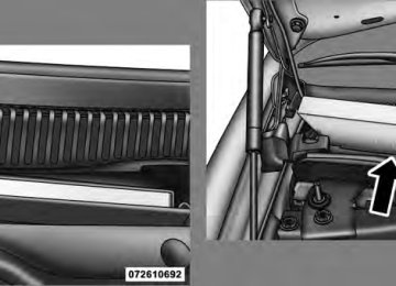
ParkSense威 uses four sensors located in the rear bumper to scan for obstacles up to 79 in (200 cm) away from the rear bumper fascia. The ParkSense威 Warning Display located above the rear window provides both visible and audible warnings to indicate the range of the object.
UNDERSTANDING THE FEATURES OF YOUR VEHICLE 159
The Warning Display contains two sets of yellow and red indicators, one set to warn of obstacles behind the left rear of the vehicle and the other set to warn of obstacles behind the right rear of the vehicle. The driver can view the indicators either through the rearview mirror or by looking at the display above the rear window. ParkSense威 dimly illuminates the two inner most yellow indicators when it is ON and detecting no obstacles. The following chart shows the warning display operation when the system is detecting an obstacle:ParkSense威 LED Display
OBSTACLE DISTANCE FROM:
INDICATOR
160 UNDERSTANDING THE FEATURES OF YOUR VEHICLE WARNING DISPLAY DISTANCES
DISPLAY INDICA-
TOR
Inner LED 1st LED 2nd LED 3rd LED 4th LED 5th LED 6th LED 7th LED
REAR CORNERS
31.5 in (80 cm) 25.5 in (65 cm) 20 in (50 cm) 16 in (40 cm) 6 in (15 cm)
REAR CENTER 79 in (200 cm) 51.2 in (130 cm) 45.3 in (115 cm) 39.3 in (100 cm) 33.5 in (85 cm) 27.6 in (70 cm) 19.7 in (50 cm) 11.8 in (30 cm)
ParkSense姞 System Usage Precautions NOTE: • Ensure that the rear bumper is free of snow, ice, mud, dirt and debris to keep the ParkSense威 Rear Park Assist system operating properly.
COLOR Yellow Yellow Yellow Yellow Yellow Yellow Red Red
AUDIBLE SIGNAL
Yes, Half Second
No No No No No
Yes, Intermittent Yes, Continuous
• Jackhammers, large trucks, and other vibrations could affect the performance of the ParkSense威 Rear Park Assist system.
• When you turn ParkSense威 off, the instrument cluster will display “PARK ASSIST DISABLED.” Further- more, once you turn ParkSense威 off, it remains off until you turn it on again, even if you cycle the ignition key. • When you move the shift lever to the REVERSE position and ParkSense威 is turned off, the instrument cluster will display “PARK ASSIST DISABLED” mes- sage for as long as the vehicle is in REVERSE. • ParkSense威, when on, will MUTE the radio when it is • If a ParkSense威 system malfunction occurs, a single chime will sound once per ignition cycle. In addition, the Electronic Vehicle Information Center (EVIC) will display “SERVICE PARK ASSIST SYSTEM” and the LED in the ParkSense威 switch will illuminate. If this occurs after making sure the rear fascia/bumper is
sounding a tone.
UNDERSTANDING THE FEATURES OF YOUR VEHICLE 161
clean and clear of snow, ice, mud, dirt, or other obstruction, see your authorized dealer for service. • Clean the ParkSense威 sensors regularly, taking care not to scratch or damage them. The sensors must not be covered with ice, snow, slush, mud, dirt, or debris. Failure to do so can result in ParkSense威 not working properly. The ParkSense威 system might not detect an obstacle behind the fascia/bumper, or it could provide a false indication that an obstacle is behind the fascia/ bumper. • Objects must not be within 12 in (30 cm) from the rear fascia/bumper while driving the vehicle. Failure to do so can result in the system misinterpreting a close object as a sensor problem, causing the “SERVICE PARK ASSIST SYSTEM” message to be displayed in the instrument cluster.162 UNDERSTANDING THE FEATURES OF YOUR VEHICLE
CAUTION!
• The ParkSense威 Rear Park Assist system is only a parking aid and it is unable to recognize every obstacle, including small obstacles. Parking curbs might be temporarily detected or not detected at all. Obstacles located above or below the sensors will not be detected when they are in close prox- imity. • The vehicle must be driven slowly when using the ParkSense威 Rear Park Assist system to be able to stop in time when the obstacle is detected. It is recommended that the driver looks over his/her shoulder when using ParkSense威.
WARNING!
• Drivers must be careful when backing up even when using the ParkSense威 Rear Park Assist sys- tem. Always check carefully behind your vehicle, look behind you, and be sure to check for pedes- trians, animals, other vehicles, obstructions, and blind spots before backing up. You are responsible for safety and must continue to pay attention to your surroundings. Failure to do so can result in serious injury or death.
(Continued)
UNDERSTANDING THE FEATURES OF YOUR VEHICLE 163
OVERHEAD CONSOLE The overhead console contains courtesy/reading lights and storage for sunglasses. Universal Garage Door Opener (HomeLink威) buttons and power sunroof switch may also be included, if equipped.
WARNING! (Continued)
• Before using the ParkSense威 Rear Park Assist system, it is strongly recommended that the ball mount and hitch ball assembly is disconnected from the vehicle when the vehicle is not used for towing. Failure to do so can result in injury or damage to vehicles or obstacles because the hitch ball will be much closer to the obstacle than the rear fascia when the warning display turns on the single flashing arc and sounds the continuous tone. Also, the ParkSense威 sensors could detect the ball mount and hitch ball assembly, depending on its size and shape, giving a false indication that an obstacle is behind the vehicle.
Overhead Console
164 UNDERSTANDING THE FEATURES OF YOUR VEHICLE Courtesy/Reading Lights
At the forward end of the console are two courtesy/ reading lights. Press the lens to turn on the light. Press it a second time to turn off the light. These lights also turn on when a door is opened, when the UNLOCK button on the Remote Keyless Entry (RKE) transmitter is pressed, when the Passive Entry door handle is used (refer to “Passive Entry” in “Things to Know Before Starting Your Vehicle” for further informa- tion) or when the dimmer control is turned fully upward, past the second detent. Sunglasses Storage At the rear of the overhead console, a compartment is provided for the storage of a pair of sunglasses.
The storage compartment access is a ⬙push/push⬙ design. Push on the raised bar on the compartment door to open. Push on the raised bar to close.
GARAGE DOOR OPENER — IF EQUIPPED HomeLink威 replaces up to three remote controls (hand- held transmitters) that operate devices such as garage door openers, motorized gates, lighting or home security systems. The HomeLink威 unit operates off your vehicle’s battery. The HomeLink威 buttons are located in the overhead console, and contain one, two or three dots/lines desig- nating the different HomeLink威 channels.
UNDERSTANDING THE FEATURES OF YOUR VEHICLE 165
WARNING!
• Your motorized door or gate will open and close while you are training the Universal Transceiver. Do not train the transceiver if people, pets, or other objects are in the path of the door or gate. Only use this transceiver with a garage door opener that has a “stop and reverse” feature as required by federal safety standards. This includes most garage door opener models manufactured after 1982. Do not use a garage door opener with- out these safety features. Call toll-free 1–800–355– 3515 or, on the Internet at www.HomeLink.com for safety information or assistance. • Vehicle exhaust contains carbon monoxide, a dan- gerous gas. Do not run your vehicle in the garage while training the transceiver. Exhaust gas can cause serious injury or death.
HomeLink威 Buttons
NOTE: HomeLink威 is disabled when the Vehicle Secu- rity Alarm is active.
166 UNDERSTANDING THE FEATURES OF YOUR VEHICLE Programming HomeLink姞
Before You Begin If you have not trained any of the HomeLink威 buttons, erase all channels before you begin training. To do this, press and hold the two outside buttons for up to 20 seconds. The EVIC will display “CLEARING CHANNELS.” Release the buttons when the EVIC mes- sage states “CHANNELS CLEARED.” It is recommended that a new battery be placed in the handheld transmitter of the device that is being copied to HomeLink威 for more efficient training and accurate transmission of the radio-frequency signal. Your vehicle should be parked outside of the garage while training. 1. Place the ignition in the RUN position.
2. Place the handheld transmitter 1 to 3 in (3 to 8 cm) from the HomeLink威 buttons while keeping the EVIC display in view. For optimal training, point the battery end of the hand- held transmitter away from the HomeLink威. 3. Simultaneously, press and hold both the chosen HomeLink威 button and the handheld transmitter button until the EVIC display changes from “CHANNEL # TRAINING” to “CHANNEL # TRAINED.” Then release both the HomeLink威 and handheld trans- mitter buttons. If the EVIC display states “DID NOT TRAIN” repeat Step 3. If the signal is too weak, replace the battery in the handheld transmitter. It may take up to 30 seconds or longer in rare cases. The garage door may open and close while you train.
NOTE: Some gate operators and garage door openers may require you to replace Step 3 with procedures noted in the “Gate Operator/Canadian Programming” section. 4. Press and hold the just-trained HomeLink威 button. If the channel has been trained, the EVIC display will now state “CHANNEL # TRANSMIT.” If the EVIC display still states “CHANNEL # TRAIN- ING” repeat Step 3. NOTE: After training a HomeLink威 channel, if the garage door does not operate with HomeLink威 and the garage door opener was manufactured after 1995, the garage door opener may have rolling code. If so, proceed to the heading “Programming A Rolling Code System.” 5. PROGRAMMING A ROLLING CODE SYSTEM At the garage door opener motor (in the garage), locate the “Learn” or “Training” button.
UNDERSTANDING THE FEATURES OF YOUR VEHICLE 167
This can usually be found where the hanging antenna wire is attached to the garage door opener motor (it is NOT the button normally used to open and close the door).1 — Garage Door Opener 2 — Training Button
168 UNDERSTANDING THE FEATURES OF YOUR VEHICLE 6. Firmly press and release the LEARN or TRAINING button. The name and color of the button may vary by manufacturer. NOTE: You have 30 seconds in which to initiate the next step after the LEARN button has been pressed. 7. Return to the vehicle and press the programmed HomeLink威 button twice (holding the button for two seconds each time). If the device is plugged in and activates, programming is complete. If the device does not activate, press the button a third time (for two seconds) to complete the training. If you have any problems, or require assistance, please call toll-free 1–800–355–3515 or, on the Internet at www.HomeLink.com for information or assistance. To program the remaining two HomeLink威 buttons, repeat each step for each remaining button. DO NOT erase the channels.
Gate Operator/Canadian Programming Canadian radio-frequency laws require transmitter sig- nals to “time-out” (or quit) after several seconds of transmission – which may not be long enough for HomeLink威 to pick up the signal during programming. Similar to this Canadian law, some U.S. gate operators are designed to “time-out” in the same manner. It may be helpful to unplug the device during the cycling process to prevent possible overheating of the garage door or gate motor. If you are having difficulties programming a garage door opener or a gate operator, replace “Programming HomeLink” Step 3 with the following: 3. Continue to press and hold the HomeLink威 button, while you press and release (“cycle”), your handheld transmitter every two seconds until HomeLink威 has
successfully accepted the frequency signal. The EVIC display will change from “CHANNEL # TRAINING” to “CHANNEL # TRAINED.” If you unplugged the device for training, plug it back in at this time. Then proceed with Step 4 under “Programming HomeLink威” earlier in this section. Using HomeLink姞 To operate, press the programmed HomeLink威 button. Activation will now occur for the trained device (i.e., garage door opener, gate operator, security system, entry door lock, home/office lighting, etc.,). The handheld transmitter of the device may also be used at any time. Reprogramming A Single HomeLink姞 Button To reprogram a channel that has been previously trained, follow these steps:
and release
UNDERSTANDING THE FEATURES OF YOUR VEHICLE 169
1. Place the ignition in the RUN position. 2. Press and hold the desired HomeLink威 button for 20 seconds until the EVIC display states “CHANNEL # TRAINING.” Do not release the button. 3. Without releasing the button, proceed with Program- ming HomeLink威 Step 2 and follow all remaining steps. Security It is advised to erase all channels before you sell or turn in your vehicle. To do this, press and hold the two outside buttons for 20 seconds until the EVIC message states “CHANNELS CLEARED.” Note that all channels will be erased. Indi- vidual channels cannot be erased. The HomeLink威 Universal Transceiver is disabled when the Vehicle Security Alarm is active.
170 UNDERSTANDING THE FEATURES OF YOUR VEHICLE Troubleshooting Tips If you are having trouble programming HomeLink威, here are some of the most common solutions: • Replace the battery in the original transmitter. • Press the LEARN button on the garage door opener to • Did you unplug the device for training, and remember
complete the training for rolling code.
to plug it back in?
If you are having any problems or require assistance, please call toll-free 1–800–355–3515 or, on the Internet at www.HomeLink.com for information or assistance. General Information This device complies with FCC rules Part 15 and Industry Canada RSS-210. Operation is subject to the following two conditions:
1. This device may not cause harmful interference 2. This device must accept any interference that may be received including interference that may cause undesired operation NOTE: The transmitter has been tested and it complies with FCC and IC rules. Changes or modifications not expressly approved by the party responsible for compli- ance could void the user’s authority to operate the device. The term “IC:” before the certification/registration num- ber only signifies that Industry Canada technical specifi- cations were met.
POWER SUNROOF — IF EQUIPPED The power sunroof switch is located between the sun visors on the overhead console.
Power Sunroof Controls
UNDERSTANDING THE FEATURES OF YOUR VEHICLE 171
WARNING!
• Never leave children in a vehicle with the key in the ignition switch (or the ignition in the ACC or RUN position, when using Keyless Go™). Occu- pants, particularly unattended children, can be- come entrapped by the power sunroof while oper- ating the power sunroof switch. Such entrapment may result in serious injury or death. • In an accident, there is a greater risk of being thrown from a vehicle with an open sunroof. You could also be seriously injured or killed. Always fasten your seat belt properly and make sure all passengers are also properly secured. • Do not allow small children to operate the sun- roof. Never allow your fingers, other body parts, or any object, to project through the sunroof opening. Injury may result.
172 UNDERSTANDING THE FEATURES OF YOUR VEHICLE Opening Sunroof — Express Press the power sunroof switch rearward and release, and the sunroof will open automatically from any posi- tion. The sunroof will open fully and then stop automati- cally. This is called “Express Open”. During Express Open operation, any movement of the power sunroof switch will stop the sunroof. Closing Sunroof — Express Press the power sunroof switch forward and release, and the sunroof will close automatically from any position. The sunroof will close fully and stop automatically. This is called “Express Close”. During Express Close opera- tion, any movement of the power sunroof switch will stop the sunroof. Pinch Protect Feature This feature will detect an obstruction in the opening of the sunroof during Express Close operation. If an ob- struction in the path of the sunroof is detected, the
sunroof will automatically retract. Remove the obstruc- tion if this occurs. Next, press the power sunroof switch forward and release to Express Close. Pinch Protect Override If a known obstruction (ice, debris, etc.) prevents closing, press the power sunroof switch forward and hold for two seconds after the reversal occurs. This allows the sunroof to move towards the closed position. NOTE: Pinch protection is disabled while the power sunroof switch is pressed. Venting Sunroof — Express Press and release the ⬙Vent⬙ button in the center of the power sunroof switch, and the sunroof will open to the vent position. This is called “Express Vent”, which oper- ates regardless of sunroof position. During Express Vent operation, any movement of the power sunroof switch will stop the sunroof.
Sunshade Operation The sunshade can be opened manually. However, the sunshade will open automatically as the sunroof opens. NOTE: The sunshade cannot be closed if the sunroof is open. Wind Buffeting Wind buffeting can be described as the perception of pressure on the ears or a helicopter-type sound in the ears. Your vehicle may exhibit wind buffeting with the windows down, or the sunroof (if equipped) in certain open or partially open positions. This is a normal occur- rence and can be minimized. If the buffeting occurs with the rear windows open, then open the front and rear windows together to minimize the buffeting. If the buffeting occurs with the sunroof open, then adjust the sunroof opening to minimize the buffeting or open any window.
UNDERSTANDING THE FEATURES OF YOUR VEHICLE 173
Sunroof Maintenance Use only a nonabrasive cleaner and a soft cloth to clean the glass panel. Ignition Off Operation The power sunroof switch will remain active for up to 60 minutes after the ignition is placed in the OFF posi- tion. Opening either front door will cancel this feature. The time for this feature is programmable. Refer to “Electronic Vehicle Information Center (EVIC)/Personal Settings (Customer-Programmable Features)” in “Under- standing Your Instrument Panel” for further information. Sunroof Fully Closed Press the power sunroof switch forward and release to ensure that the sunroof is fully closed.
174 UNDERSTANDING THE FEATURES OF YOUR VEHICLE ELECTRICAL POWER OUTLETS There are two 12 Volt (13 Amp) electrical power outlets on this vehicle. Both of the power outlets are protected by a fuse. Insert cigar lighter or accessory plug into the power outlets for use to ensure proper operation. NOTE: • To ensure proper operation a MOPAR威 knob and • Do not exceed the maximum power of 160 Watts (13
Amps) at 12 Volts. If the 160 Watt (13 Amp) power rating is exceeded the fuse protecting the system will need to be replaced.element must be used.
The 12 Volt power outlet next to the ash receiver tray has power available only when the ignition is placed in the ACC or RUN position.
Front Power Outlet
WARNING!
Do not place ashes inside the cubby bin located on the center console on vehicle’s not equipped with the ash receiver tray. A fire leading to bodily injury could result.
The center console outlet is powered directly from the battery (power available at all times). Items plugged into this outlet may discharge the battery and/or prevent the engine from starting.
UNDERSTANDING THE FEATURES OF YOUR VEHICLE 175
Center Console Power Outlet
WARNING!
To avoid serious injury or death: • Only devices designed for use in this type of outlet should be inserted into any 12 Volt outlet.
(Continued)
176 UNDERSTANDING THE FEATURES OF YOUR VEHICLE
WARNING! (Continued)
• Do not touch with wet hands. • Close the lid when not in use and while driving • If this outlet is mishandled, it may cause an
the vehicle.
electric shock and failure.
CAUTION!
• Many accessories that can be plugged in draw power from the vehicle’s battery even when not in use (i.e., cellular phones, etc.). Eventually, if plugged in long enough, the vehicle’s battery will discharge sufficiently to degrade battery life and/or prevent the engine from starting.
(Continued)
CAUTION! (Continued)
• Accessories that draw higher power (i.e., coolers, vacuum cleaners, lights, etc.) will degrade the battery even more quickly. Only use these inter- mittently and with greater caution. • After the use of high power draw accessories or long periods of the vehicle not being started (with accessories still plugged in), the vehicle must be driven a sufficient length of time to allow the alternator to recharge the vehicle’s battery. • Power outlets are designed for accessory plugs only. Do not hang any type of accessory or acces- sory bracket from the plug. Improper use of the power outlet can cause damage.
CUPHOLDERS
Front Seat Cupholders The cupholders are located in the forward edge of the center console.
UNDERSTANDING THE FEATURES OF YOUR VEHICLE 177
Rear Seat Cupholders The rear seat cupholders are located in the center armrest between the rear seats. The cupholders are positioned forward in the armrest and side-by-side to provide convenient access to beverage cans or bottles while maintaining a resting place for the rear occupants elbows.
Front Seat Cupholders
Rear Seat Cupholders
178 UNDERSTANDING THE FEATURES OF YOUR VEHICLE STORAGE
Console Features The center console contains two shift bezel cubby bins with rubber mats for holding small items. For vehicles not equipped with navigation radio, the console also contains an extra storage bin located below the climate control, which holds up to four CD jewel cases. Two separate storage compartments are also located underneath the armrest.
1 — Release button for bottom compartment 2 — Release button for top compartment 3 — Top Compartment 4 — Bottom Compartment. (You can access this compartment directly, without first exposing the upper compartment, by oper- ating the Release Button for the bottom compartment with the armrest down.)
The top compartment holds small items, such as a pen and note pad, while the larger bottom compartment will hold CDs and alike. The bottom compartment also con- tains a 12 Volt power outlet and a molded-in coin holder (designed to hold various size coins). A slot in the left and right side of the top compartment provides clearance for power cords to pass conveniently out of the bin with the lid closed. This feature is ideal for games, laptop’s, cellular phones or other electrical equipment. The con- sole’s front opening lid allows for easy access to these compartments. Cargo Area The 60/40 split-folding rear seat provides cargo-carrying versatility. The seatbacks fold down easily by pulling nylon tabs between the seatbacks and the bolsters. When the seats are folded down, they provide a continuous, nearly-flat extension of the load floor.
UNDERSTANDING THE FEATURES OF YOUR VEHICLE 179
WARNING!
The weight and position of cargo and passengers can change the vehicle center of gravity and vehicle handling. To avoid loss of control resulting in per- sonal injury, follow these guidelines for loading your vehicle: • Always place cargo evenly on the cargo floor. Put heavier objects as low and as far forward as possible. • Place as much cargo as possible in front of the rear axle. Too much weight or improperly placed weight over or behind the rear axle can cause the rear of the vehicle to sway. • Do not pile luggage or cargo higher than the top of the seatback. This could impair visibility or be- come a dangerous projectile in a sudden stop or collision.
180 UNDERSTANDING THE FEATURES OF YOUR VEHICLE When the seatback is folded to the upright position, make sure it is latched by strongly pulling on the top of the seatback above the seat strap.
WARNING!
• Be certain that the seatback is securely locked into position. If the seatback in not securely locked into position, the seat will not provide the proper stability for child seats and/or passengers. An improperly latched seat could cause serious injury. • The cargo area in the rear of the vehicle (with the rear seatbacks in the locked-up or folded down position) should not be used as a play area by children when the vehicle is in motion. They could be seriously injured in an accident. Children should be seated and using the proper restraint system.
(Continued)
WARNING! (Continued)
• To help protect against personal injury, passengers should not be seated in the rear cargo area. The rear cargo space is intended for load carrying purposes only, not for passengers, who should sit in seats and use seat belts.
CARGO AREA FEATURES
Trunk Mat — If Equipped A reversible trunk mat covers the bottom of the cargo area. The rubber side of the mat is used to protect the interior of the trunk from mud, snow, and debris. It provides a nonskid surface to keep cargo from sliding.
REAR WINDOW FEATURES
Rear Window Defroster
The rear window defroster button is located on the climate control. Press this button to turn on the rear window defroster and the heated outside mirrors (if equipped). An indicator in the button will illuminate when the rear window defroster is on. The rear window defroster automatically turns off after approximately 10 minutes. For an additional five minutes of operation, press the button a second time.
CAUTION!
Failure to follow these cautions can cause damage to the heating elements:
(Continued)
UNDERSTANDING THE FEATURES OF YOUR VEHICLE 181
CAUTION! (Continued)
• Use care when washing the inside of the rear window. Do not use abrasive window cleaners on the interior surface of the window. Use a soft cloth and a mild washing solution, wiping parallel to the heating elements. Labels can be peeled off after soaking with warm water. • Do not use scrapers, sharp instruments, or abra- sive window cleaners on the interior surface of the window. • Keep all objects a safe distance from the window.
UNDERSTANDING YOUR INSTRUMENT PANEL
CONTENTS
䡵 Instrument Panel Features 䡵 Instrument Cluster 䡵 Instrument Cluster Descriptions 䡵 Electronic Vehicle Information Center (EVIC)
. . . . . . . . . . . . . . . 187
. . . . . . . . . . . . . . . . . . . . 188
. . . . . . . . . . . 189
. . 199▫ Electronic Vehicle Information Center (EVIC)
Displays . . . . . . . . . . . . . . . . . . . . . . . . . . . 202
▫ Engine Oil Change Indicator System . . . . . . . 206
▫ Trip Functions . . . . . . . . . . . . . . . . . . . . . . 206
▫ Performance Pages — If Equipped . . . . . . . . 208▫ Keyless Go Display — If Equipped . . . . . . . . 212
▫ Driver-Selectable Surround Sound (DSS)– If Equipped . . . . . . . . . . . . . . . . . . . . . . . 212
▫ Compass Display . . . . . . . . . . . . . . . . . . . . 213
▫ Uconnect™ GPS — If Equipped . . . . . . . . . . 215
▫ System Warnings (Customer InformationFeatures)
. . . . . . . . . . . . . . . . . . . . . . . . . . 216
▫ Personal Settings (Customer-Programmable
Features)
. . . . . . . . . . . . . . . . . . . . . . . . . . 216
䡵 Setting The Analog Clock . . . . . . . . . . . . . . . . 221184 UNDERSTANDING YOUR INSTRUMENT PANEL 䡵 Media Center 730N/430 (RER/REN/RBZ) — AM/FM Stereo Radio And CD/DVD/HDD/ NAV — If Equipped . . . . . . . . . . . . . . . . . . . . 222
▫ Operating Instructions — Voice CommandSystem — If Equipped . . . . . . . . . . . . . . . . . 222
▫ Operating Instructions —
Uconnect™ phone — If Equipped . . . . . . . . 222
▫ Clock Setting Procedure — RBZ Radio . . . . . 222
▫ Clock Setting Procedure —RER/REN Radio . . . . . . . . . . . . . . . . . . . . . 224
䡵 Media Center 130 (RES) — AM/FM Stereo
Radio With CD Player (MP3 AUX Jack). . . . . . . 226
▫ Operating Instructions — Radio Mode . . . . . 226
▫ Operation Instructions — CD Mode For CDAnd MP3 Audio Play . . . . . . . . . . . . . . . . . 229
▫ Notes On Playing MP3 Files . . . . . . . . . . . . 232
▫ Operation Instructions - Auxiliary Mode . . . . 234䡵 Media Center 130 (RES/RSC) — AM/FM
Stereo Radio With CD Player (MP3 AUX Jack) And Sirius Radio . . . . . . . . . . . . . . . . . . . . . . 235
▫ Operating Instructions — Radio Mode . . . . . 235
▫ Operation Instructions — CD Mode For CDAnd MP3 Audio Play . . . . . . . . . . . . . . . . . 241
▫ Notes On Playing MP3 Files . . . . . . . . . . . . 243
▫ List Button (CD Mode For MP3 Play) . . . . . . 246
▫ Info Button (CD Mode For MP3 Play) . . . . . . 246䡵 Universal Consumer Interface (UCI) 0.5
— If Equipped . . . . . . . . . . . . . . . . . . . . . . . . 247
▫ Connecting The iPod威 . . . . . . . . . . . . . . . . . 248▫ Using This Feature . . . . . . . . . . . . . . . . . . . 248
▫ Controlling The iPod威 Using RadioButtons . . . . . . . . . . . . . . . . . . . . . . . . . . . 248
▫ Play Mode . . . . . . . . . . . . . . . . . . . . . . . . . 249
▫ List Or Browse Mode . . . . . . . . . . . . . . . . . 250䡵 Uconnect™ Multimedia (Satellite Radio)
— If Equipped (REN/RER/RES Radios Only) . . 252
▫ System Activation . . . . . . . . . . . . . . . . . . . . 252
▫ Electronic Serial Number/SiriusIdentification Number (ESN/SID) . . . . . . . . . 253
UNDERSTANDING YOUR INSTRUMENT PANEL 185
▫ Operating Instructions - Uconnect™
Multimedia (Satellite) Mode . . . . . . . . . . . . . 254
▫ Operating Instructions - Uconnect™ Phone
(If Equipped)
. . . . . . . . . . . . . . . . . . . . . . . 256
䡵 Kicker威 High Performance Sound System With
Driver-Selectable Surround (DSS) – If Equipped . . . . . . . . . . . . . . . . . . . . . . . . . 257
䡵 Video Entertainment System (VES)™
— If Equipped . . . . . . . . . . . . . . . . . . . . . . . . 258
▫ Kicker威 Mobile Surround (KMS1)威– If Equipped . . . . . . . . . . . . . . . . . . . . . . . 260
▫ Selecting Uconnect™ Multimedia (Satellite)
Mode . . . . . . . . . . . . . . . . . . . . . . . . . . . . . 253
▫ Satellite Antenna . . . . . . . . . . . . . . . . . . . . . 253
▫ Reception Quality . . . . . . . . . . . . . . . . . . . . 254䡵 Remote Sound System Controls
— If Equipped . . . . . . . . . . . . . . . . . . . . . . . . 260
䡵 CD/DVD Disc Maintenance . . . . . . . . . . . . . . 262
䡵 Radio Operation And Cellular Phones . . . . . . . 263186 UNDERSTANDING YOUR INSTRUMENT PANEL 䡵 Climate Controls . . . . . . . . . . . . . . . . . . . . . . 263
. . . . . . . . . . 263▫ Automatic Temperature Control
▫ Operating Tips . . . . . . . . . . . . . . . . . . . . . . 268
INSTRUMENT PANEL FEATURES
UNDERSTANDING YOUR INSTRUMENT PANEL 187
1 — Air Outlet 2 — Instrument Cluster 3 — Hazard Switch 4 — Analog Clock 5 — Electronic Stability Program Off Button* 6 — Glove Compartment
7 — Radio 8 — Climate Control 9 — Heated Seat Switch* 10 — Power Outlet 11 — Ash Tray* 12 — Storage Compartment*
13 — Ignition Switch 14 — Hood Release 15 — Trunk Release Button 16 — Headlight Switch * If Equipped
188 UNDERSTANDING YOUR INSTRUMENT PANEL INSTRUMENT CLUSTER
INSTRUMENT CLUSTER DESCRIPTIONS
1. Electronic Speed Control / Adaptive Cruise Control (ACC) Indicator Light — If Equipped
This light will turn on when the electronic speed control or Adaptive Cruise Control (ACC) is ON.
2. Low Fuel Indicator Light
This light will turn on and a single chime will sound when the fuel level drops to approximately 1/8 tank.
3. Front Fog Light Indicator
This indicator will illuminate when the front fog lights are on.
4. Turn Signal Indicators
The arrow will flash with the exterior turn signal when the turn signal lever is operated.
UNDERSTANDING YOUR INSTRUMENT PANEL 189
NOTE: • A continuous chime will sound if the vehicle is driven more than 1 mile (1.6 km) with either turn signal on. • Check for an inoperative outside light bulb if either
indicator flashes at a rapid rate.
5. Speedometer Indicates vehicle speed. 6. Electronic Vehicle Information Center (EVIC) Display / Odometer The odometer shows the total distance the vehicle has been driven. U.S. Federal regulations require that upon transfer of vehicle ownership, the seller certify to the purchaser the correct mileage that the vehicle has been driven. If your odometer needs to be repaired or serviced, the repair technician should leave the odometer reading the same as it was before the repair or service. If s/he cannot do so, then the odometer must be set at zero, and a sticker must be placed in the door jamb stating what the
190 UNDERSTANDING YOUR INSTRUMENT PANEL mileage was before the repair or service. It is a good idea for you to make a record of the odometer reading before the repair/service, so that you can be sure that it is properly reset, or that the door jamb sticker is accurate if the odometer must be reset at zero. This display shows the Electronic Vehicle Information Center (EVIC) messages when the appropriate conditions exist. (Refer to “Electronic Vehicle Information Center (EVIC)” for further information). Loose Fuel Filler Cap Message If the vehicle diagnostic system determines that the fuel filler cap is loose, improperly installed, or damaged, a “Check Gascap” message will display in the odometer display area. Tighten the fuel filler cap properly and press the TRIP ODOMETER button to turn off the message. If the problem continues, the message will appear the next time the vehicle is started.
A loose, improperly installed, or damaged fuel filler cap may also turn on the Malfunction Indicator Light (MIL). 7. Tachometer The red segments indicate the maximum permissible engine revolutions per minute (RPM x 1000) for each gear range. Ease up on the accelerator before reaching the red area. 8. Engine Temperature Warning Light
This light will turn on and a single chime will sound to warn of an overheated engine condition. When this light turns on, the engine temperature is critically hot. The vehicle should be turned OFF immediately and serviced as soon as possible. 9. Anti-Lock Brake (ABS) Light
This light monitors the Anti-Lock Brake System (ABS). The light will turn on when the ignition switch is placed in the RUN position and may stay on for as long as four seconds.
If the ABS light remains on or turns on while driving, then the Anti-Lock portion of the brake system is not functioning and service is required. However, the con- ventional brake system will continue to operate normally if the BRAKE warning light is not on. If the ABS light is on, the brake system should be serviced as soon as possible to restore the benefits of Anti-Lock brakes. If the ABS light does not turn on when the ignition switch placed in the RUN position, have the light inspected by an authorized dealer. 10. Electronic Stability Program (ESP) / Brake Assist System (BAS) Malfunction Indicator Light
The yellow Electronic Stability Program (ESP) / Brake Assist System (BAS) Malfunction Indi- cator Light will turn on when the key in the ignition switch placed in the RUN position. The light should go out with the engine running. If the light remains on after several ignition cycles, and the
UNDERSTANDING YOUR INSTRUMENT PANEL 191
vehicle has been driven several miles (kilometers) at speeds greater than 30 mph (48 km/h), see an authorized dealer as soon as possible to have the problem diagnosed and corrected.WARNING!
If a warning light remains on the system may not be working and you will not have the benefit of ESP or BAS. Under certain driving conditions, where ESP or BAS would be beneficial, you - if you have not adjusted your driving speeds and stopping in or to account for the lack of the feature, may be in acci- dent.
11. Airbag Warning Light
This light will turn on for six to eight seconds as a bulb check when the ignition switch is first placed in the RUN position. If the light is either not on during starting, or stays on, or turns on
192 UNDERSTANDING YOUR INSTRUMENT PANEL while driving, then have the system inspected at an authorized dealer as soon as possible. Refer to “Occupant Restraints” in “Things To Know Before Starting Your Vehicle” for further information. 12. Brake Warning Light
This light monitors various brake functions, including brake fluid level and parking brake application. If the brake light turns on, it may indicate that the parking brake is applied, that the brake fluid level is low, or that there is a problem with the anti-lock brake system reservoir. If the light remains on when the parking brake has been disengaged, and the fluid level is at the full mark on the master cylinder reservoir, it indicates a possible brake hydraulic system malfunction. In this case, the light will remain on until the condition has been corrected. The dual brake system provides a reserve braking capac- ity in the event of a failure to a portion of the hydraulic
system. A leak in either half of the dual brake system is indicated by the Brake Warning Light which will turn on when the brake fluid level in the master cylinder has dropped below a specified level. The light will remain on until the cause is corrected. NOTE: The light may flash momentarily during sharp cornering maneuvers which change fluid level condi- tions. The vehicle should have service performed, and the brake fluid level checked. If brake failure is indicated, immediate repair is neces- sary.
WARNING!
Driving a vehicle with the brake light on is danger- ous. Part of the brake system may have failed. It will take longer to stop the vehicle. You could have an accident. Have the vehicle checked immediately.
Vehicles equipped with the Anti-Lock Brake System (ABS), are also equipped with Electronic Brake Force Distribution (EBD). In the event of an EBD failure, the Brake Warning Light will turn on along with the ABS Light. Immediate repair to the ABS system is required. Operation of the Brake Warning Light can be checked by turning the ignition switch from the OFF position to the RUN position. The light should illuminate for approxi- mately two seconds. The light should then turn off unless the parking brake is applied or a brake fault is detected. If the light does not illuminate, have the light inspected by an authorized dealer. The light also will turn on when the parking brake is applied with the ignition switch in the RUN position. NOTE: This light shows only that the parking brake is applied. It does not show the degree of brake application.
UNDERSTANDING YOUR INSTRUMENT PANEL 193
13. Electronic Stability Program (ESP) / Traction Control System (TCS) Indicator Light
If this indicator light flashes during accelera- tion, ease up on the accelerator and apply as little throttle as possible. Adapt your speed and driving to the prevailing road conditions, and do not switch off the Electronic Stability Program (ESP). 14. Temperature Gauge The temperature gauge shows engine coolant tempera- ture. Any reading within the normal range indicates that the engine cooling system is operating satisfactorily. The gauge pointer will likely indicate a higher tempera- ture when driving in hot weather, up mountain grades, or when towing a trailer. It should not be allowed to exceed the upper limits of the normal operating range.
194 UNDERSTANDING YOUR INSTRUMENT PANEL
CAUTION!
WARNING!
Driving with a hot cooling system could damage your vehicle. If the temperature gauge reads 240°F (116°C) or greater, pull over and stop the vehicle. Idle the vehicle with the air conditioner turned off until the pointer drops back into the normal range 200– 230°F (93–110°C). If the pointer remains at 240°F (116°C) or greater and you hear a chime, turn the engine OFF immediately, and call for service.
A hot engine cooling system is dangerous. You or others could be badly burned by steam or boiling coolant. You may want to call a service center if your vehicle overheats. If you decide to look under the hood yourself, refer to “Maintaining Your Vehicle” and follow the warnings under the Cooling System Pressure Cap paragraph.
15. Trip Odometer Button Press this button to change the display from odometer to either of two trip odometer settings. The letter “A” or “B” will appear when in the trip odometer mode. Push in and hold the button for two seconds to reset the trip odometer to 0 miles (km). The odometer must be in TRIP mode to reset it.
16. High Beam Light This light will turn on when the high beam headlights are ON. Push the multifunction lever away from the steering wheel to switch the headlights to high beam. 17. Shift Lever Indicator The Shift Lever Indicator is self-contained within the instrument cluster. It displays the gear position of the automatic transmission. 18. Seat Belt Reminder Light
This light will turn on for five to eight seconds as a bulb check when the ignition switch is first placed in the RUN position. A chime will sound if the driver’s seat belt is unbuckled during the bulb check. The Seat Belt Warning Light will flash, or remain on continuously, if the driver’s seat belt remains unbuckled after the bulb check or when driving. Refer to “Occupant Restraints” in “Things To Know Before Starting Your Vehicle” for further information.
UNDERSTANDING YOUR INSTRUMENT PANEL 195
19. Vehicle Security Light — If Equipped
This light will flash at a fast rate for approxi- mately 15 seconds, when the vehicle security alarm is arming, and then will flash slowly until the vehicle is disarmed.
20. Fuel Gauge The pointer shows the level of fuel in the fuel tank when the ignition switch is placed in the RUN position. 21. Electronic Throttle Control (ETC) Light
This light will turn on briefly as a bulb check when the ignition switch is placed in the RUN position. This light will also turn on while the engine is running if there is a problem with the
Electronic Throttle Control (ETC) system. If the light comes on while the engine is running, safely bring the vehicle to a complete stop as soon as possible, place the shift lever in PARK, and cycle the ignition through the ACC and RUN positions. The light should
196 UNDERSTANDING YOUR INSTRUMENT PANEL turn off. If the light remains lit with the engine running, your vehicle will usually be drivable. However, see an authorized dealer for service as soon as possible. If the light is flashing when the engine is running, immediate service is required. In this case, you may experience reduced performance, an elevated/rough idle or engine stall, and your vehicle may require towing. Also, have the system checked by an authorized dealer if the light does not come on during starting. 22. Tire Pressure Monitoring Telltale Light
Each tire, including the spare (if provided), should be checked monthly, when cold and inflated to the inflation pressure recommended by the vehicle manufacturer on the vehicle placard or tire inflation pressure label. (If your vehicle has tires of a different size than the size indicated on the vehicle placard or tire inflation pressure label, you should determine the proper tire inflation pressure for those tires.)
As an added safety feature, your vehicle has been equipped with a Tire Pressure Monitoring System (TPMS) that illuminates a low tire pressure telltale when one or more of your tires is significantly under-inflated. Accordingly, when the low tire pressure telltale illumi- nates, you should stop and check your tires as soon as possible, and inflate them to the proper pressure. Driving on a significantly under-inflated tire causes the tire to overheat and can lead to tire failure. Under-inflation also reduces fuel efficiency and tire tread life, and may affect the vehicle’s handling and stopping ability. Please note that the TPMS is not a substitute for proper tire maintenance, and it is the driver’s responsibility to maintain correct tire pressure, even if under-inflation has not reached the level to trigger illumination of the TPMS low tire pressure telltale.
Your vehicle has also been equipped with a TPMS malfunction indicator to indicate when the system is not operating properly. The TPMS malfunction indicator is combined with the low tire pressure telltale. When the system detects a malfunction, the telltale will flash for approximately one minute and then remain continuously illuminated. This sequence will continue upon subse- quent vehicle start-ups as long as the malfunction exists. When the malfunction indicator is illuminated, the sys- tem may not be able to detect or signal low tire pressure as intended. TPMS malfunctions may occur for a variety of reasons, including the installation of replacement or alternate tires or wheels on the vehicle that prevent the TPMS from functioning properly. Always check the TPMS malfunction telltale after replacing one or more tires or wheels on your vehicle, to ensure that the replacement or alternate tires and wheels allow the TPMS to continue to function properly.
UNDERSTANDING YOUR INSTRUMENT PANEL 197
CAUTION!
The TPMS has been optimized for the original equipment tires and wheels. TPMS pressures and warning have been established for the tire size equipped on your vehicle. Undesirable system opera- tion or sensor damage may result when using re- placement equipment that is not of the same size, type, and/or style. Aftermarket wheels can cause sensor damage. Do not use tire sealant from a can, or balance beads if your vehicle is equipped with a TPMS, as damage to the sensors may result.
23. Charging System Light
This light shows the status of the electrical charg- ing system. The light should come on when the ignition switch is first placed in the RUN position and remain on briefly as a bulb check. If the light stays on or comes on while driving, turn off some of the vehicle’s
198 UNDERSTANDING YOUR INSTRUMENT PANEL non-essential electrical devices or increase engine speed (if at idle). If the charging system light remains on, it means that the vehicle is experiencing a problem with the charging system. Obtain SERVICE IMMEDIATELY. See an authorized dealer. If jump starting is required, refer to “Jump Starting Procedures” in “What To Do In Emergencies”. 24. Malfunction Indicator Light (MIL)
The Malfunction Indicator Light (MIL) is part of an onboard diagnostic system called OBD. The OBD system monitors engine and automatic transmission control systems. The MIL will turn on when the ignition is in the RUN position before engine start. If the MIL does not come on when turning the key from OFF to RUN, have the condition checked promptly.
Certain conditions such as a loose or missing gas cap, poor fuel quality, etc., may illuminate the MIL after engine start. The vehicle should be serviced if the MIL stays on through several of your typical driving cycles. In most situations, the vehicle will drive normally and will not require towing.
CAUTION!
Prolonged driving with the MIL on could cause damage to the engine control system. It also could affect fuel economy and drivability. If the MIL is flashing, severe catalytic converter damage and power loss will soon occur. Immediate service is required.
UNDERSTANDING YOUR INSTRUMENT PANEL 199
Do not operate the vehicle until the cause is corrected. This light does not indicate how much oil is in the engine. The engine oil level must be checked using the procedure shown in “Maintaining Your Vehicle”.ELECTRONIC VEHICLE INFORMATION CENTER (EVIC) The Electronic Vehicle Information Center (EVIC) fea- tures a driver-interactive display that is located in the instrument cluster.
WARNING!
A malfunctioning catalytic converter, as referenced above, can reach higher temperatures than in normal operating conditions. This can cause a fire if you drive slowly or park over flammable substances such as dry plants or wood or cardboard, etc. This could result in death or serious injury to the driver, occu- pants or others.
25. Oil Pressure Warning Light
This light indicates low engine oil pressure. The light should turn on momentarily when the engine is started. If the light turns on while driving, stop the vehicle, and shut OFF the engine as soon as possible. A single chime will sound when this light turns on.
200 UNDERSTANDING YOUR INSTRUMENT PANEL
Electronic Vehicle Information Center (EVIC)
This system conveniently allows the driver to select a variety of useful information by pressing the switches mounted on the steering wheel. The EVIC consists of the following: • System status
• Vehicle information warning message displays • Tire Pressure Monitor System (if equipped) • Personal Settings (Customer-Programmable Features) • Compass display • Outside temperature display • Trip computer functions • Uconnect™ Phone displays (if equipped) • Uconnect™ gps screens (if equipped) • Audio mode display • Surround Sound modes (if equipped with Driver- • Performance Pages (if equipped)
Selectable Surround [DSS])
The system allows the driver to select information by pressing the following buttons mounted on the steering wheel.
Press and release the MENU button and the mode displayed will change between Trip Functions, Performance Pages (if equipped), Uconnect™ gps (if equipped), System Warn- ings, System Status, and Personal Settings.
Press the FUNCTION SELECT button to accept a selection. The FUNCTION SELECT button also functions as a remote sound system con- trol. Refer to “Remote Sound System Controls”.
MENU Button
FUNCTION
SELECT Button
UNDERSTANDING YOUR INSTRUMENT PANEL 201
Press the SCROLL button to scroll through Trip Functions, Performance Pages (if equipped), Uconnect™ gps (if equipped), System Status Messages, and Personal Settings (Customer- Programmable Features). The SCROLL button also functions as a remote sound system con-SCROLL Button
trol. Refer to “Remote Sound System Controls”.
Press the AUDIO MODE button to select the Compass/Temp/Audio screen. Along with compass reading and outside temperature, this screen will display radio and media mode information depending on which radio is in the vehicle. Refer to “Remote Sound System Controls”.
AUDIO MODE Button
202 UNDERSTANDING YOUR INSTRUMENT PANEL Electronic Vehicle Information Center (EVIC) Displays When the appropriate conditions exist, the EVIC displays the following messages: • Turn Signal On (with a continuous warning chime if the vehicle is driven more than 1 mile [1.6 km] with either turn signal on) • Left Front Turn Signal Light Out (with a single chime) • Left Rear Turn Signal Light Out (with a single chime) • Right Front Turn Signal Light Out (with a single • Right Rear Turn Signal Light Out (with a single chime) • RKE Battery Low (with a single chime) • Memory #1/#2 Profile Set • Memory #1/#2 Profile Recall
chime)
single chime)
a single chime)
chime if speed is above 1 mph [1.6 km/h])
• Memory System Disabled – Vehicle Not In PARK (with • Memory System Disabled – Seat Belt Buckled (with a • Personal Settings Not Available – Vehicle Not in PARK • Left/Right Front Door Ajar (one or more, with a single • Left/Right Rear Door Ajar (one or more, with a single • Door(s) Ajar (with a single chime if vehicle is in • Trunk Ajar (with a single chime) • Low Washer Fluid (with a single chime) • Oil Pressure • Oil Change Required (with single chime)
chime if speed is above 1 mph [1.6 km/h])
motion)
• ACC Off — When the Adaptive Cruise Control (ACC) system is turned off. Refer to “Adaptive Cruise Con- trol (ACC)” in “Understanding The Features Of Your Vehicle” (if equipped). • ACC Ready — When the Adaptive Cruise Control (ACC) system is activated. Refer to “Adaptive Cruise Control (ACC)” in “Understanding The Features Of Your Vehicle” (if equipped). • ACC Set — After setting the desired speed in the Adaptive Cruise Control (ACC) system. Refer to “Adaptive Cruise Control (ACC)” in “Understanding The Features Of Your Vehicle” (if equipped). • Driver Override — If you apply the accelerator after setting the desired speed in the Adaptive Cruise Control (ACC) system. Refer to “Adaptive Cruise Control (ACC)” in “Understanding The Features Of Your Vehicle” (if equipped).
UNDERSTANDING YOUR INSTRUMENT PANEL 203
• Distance Set — After changing the desired following distance in the Adaptive Cruise Control (ACC) system, this message will display momentarily. Refer to “Adaptive Cruise Control (ACC)” in “Understanding The Features Of Your Vehicle” (if equipped). • Attention — If the Adaptive Cruise Control (ACC) system predicts that its maximum braking level is not sufficient to maintain the set distance, this message will flash and a chime will sound while ACC continues to apply its maximum braking capacity. When this occurs, you should immediately apply the brakes as needed to maintain a safe distance from the vehicle ahead. Refer to “Adaptive Cruise Control (ACC)” in “Understanding The Features Of Your Vehicle” (if equipped).
204 UNDERSTANDING YOUR INSTRUMENT PANEL
• ACC Blinded — If the Adaptive Cruise Control (ACC) system deactivates due to performance limiting con- ditions. Refer to “Adaptive Cruise Control (ACC)” in “Understanding The Features Of Your Vehicle” (if equipped). • ACC Unavailable — If the Adaptive Cruise Control (ACC) system turns off due to a temporary malfunc- tion that limits functionality. Refer to “Adaptive Cruise Control (ACC)” in “Understanding The Fea- tures Of Your Vehicle” (if equipped). • Service ACC — If the Adaptive Cruise Control (ACC) system turns off due to an internal system fault that requires service from an authorized dealer. Refer to “Adaptive Cruise Control (ACC)” in “Understanding The Features Of Your Vehicle” (if equipped). • Adjustable Pedals Disabled – Cruise Engaged (with a single chime) — only available on vehicles equipped with memory seats.
• Adjustable Pedals Disabled – Vehicle In REVERSE (with a single chime) — only available on vehicles equipped with memory seats.
• Channel # Transmit • Channel # Training • Channel # Trained • Clearing Channels • Channels Cleared • Did Not Train • Left Front Low Pressure (with a single chime). Refer to information on “Tire Pressure” and “Tire Pressure Monitor” under “Starting And Operating.” • Left Rear Low Pressure (with a single chime). Refer to information on “Tire Pressure” and “Tire Pressure Monitor” under “Starting And Operating.”
• Right Front Low Pressure (with a single chime). Refer to information on “Tire Pressure” and “Tire Pressure Monitor” under “Starting And Operating.” • Right Rear Low Pressure (with a single chime). Refer to information on “Tire Pressure” and “Tire Pressure Monitor” under “Starting And Operating.” • Check TPM System (with a single chime). Refer to information on “Tire Pressure” and “Tire Pressure Monitor” under “Starting And Operating.” • Check Gascap (refer to “Adding Fuel” in “Starting • Service Park Assist System (with a single chime) • Turn To Run (refer to “Remote Starting System” in • Upshift
“Things To Know Before Starting Your Vehicle”)
And Operating”)
Pages)
Pages)
UNDERSTANDING YOUR INSTRUMENT PANEL 205
• 0-60 mph (0-100 km/h) (if equipped with Performance • Braking Distance (if equipped with Performance • 1/8 Mile (if equipped with Performance Pages) • 1/4 Mile (if equipped with Performance Pages) • Instantaneous G-Force (if equipped with Performance • Peak G-Force (if equipped with Performance Pages) • Digital Speedometer (if equipped with Performance
Pages)
Pages)
206 UNDERSTANDING YOUR INSTRUMENT PANEL Engine Oil Change Indicator System
Oil Change Required Your vehicle is equipped with an engine oil change indicator system. The “Oil Change Required” message will flash in the EVIC display for approximately 10 sec- onds after a single chime has sounded, to indicate the next scheduled oil change interval. The engine oil change indicator system is duty cycle based, which means the engine oil change interval may fluctuate, dependent upon your personal driving style. Unless reset, this message will continue to display each time you turn the ignition switch to the ON/RUN position. To turn off the message temporarily, press and release the MENU button. To reset the oil change indica- tor system (after performing the scheduled maintenance) refer to the following procedure. 1. Turn the ignition switch to the ON position (Do not start the engine).
2. Fully depress the accelerator pedal, slowly, three times within 10 seconds. 3. Turn the ignition switch to the OFF/LOCK position. If the indicator message illuminates when you NOTE: start the vehicle, the oil change indicator system did not reset. If necessary, repeat this procedure. Trip Functions Press and release the MENU button until one of the following Trip Functions displays in the EVIC: • Average Fuel Economy • Distance To Empty • Trip A • Trip B • Elapsed Time • Display Units of Measure in
Press the SCROLL button to cycle through all the Trip Computer functions. The Trip Functions mode displays the following informa- tion. • Average Fuel Economy Shows the average fuel economy since the last reset. When the fuel economy is reset, the display will read “RESET” or show dashes for two seconds. Then, the history information will be erased, and the averaging will continue from the last fuel average reading before the reset. • Distance To Empty (DTE) Shows the estimated distance that can be traveled with the fuel remaining in the tank. This estimated distance is determined by a weighted average of the instantaneous and average fuel economy, according to the current fuel tank level. DTE cannot be reset through the FUNCTION SELECT button.
UNDERSTANDING YOUR INSTRUMENT PANEL 207
NOTE: Significant changes in driving style or vehicle loading will greatly affect the actual drivable distance of the vehicle, regardless of the DTE displayed value. When the DTE value is less than 30 miles (48 km) estimated driving distance, the DTE display will change to a text display of ⬙LOW FUEL.⬙ This display will continue until the vehicle runs out of fuel. Adding a significant amount of fuel to the vehicle will turn off the ⬙LOW FUEL⬙ text and a new DTE value will display. • Trip A Shows the total distance traveled for Trip A since the last reset. • Trip B Shows the total distance traveled for Trip B since the last reset.208 UNDERSTANDING YOUR INSTRUMENT PANEL
• Elapsed Time Shows the total elapsed time of travel since the last reset when the ignition switch is in the ACC position. Elapsed time will increment when the ignition switch is in the ON or START position. • Display Units of Measure in To make your selection, press and release the FUNC- TION SELECT button until “ENGLISH” or “METRIC” appears. To Reset The Display Reset will only occur while a resettable function is being displayed. Press and release the FUNCTION SELECT button once to clear the resettable function being dis- played. To reset all resettable functions, press and release the FUNCTION SELECT button a second time within three seconds of resetting the currently-displayed func- tion (>Reset ALL will display during this three-second window).
Performance Pages — If Equipped
WARNING!
Measurement of vehicle statistics with the Perfor- mance Pages is intended for off-highway or off-road use only and should not be done on any public roadways. It is recommended that these features be used in a controlled environment and within the limits of the law. The capabilities of the vehicle as measured by the performance pages must never be exploited in a reckless or dangerous manner, which can jeopardize the user’s safety or the safety of others. Only a safe, attentive, and skillful driver can prevent accidents.
The Performance Pages include the following features: • 0-60 mph (0-100 km/h) • Braking Distance
• 1/8 Mile • 1/4 Mile • Instantaneous G-Force • Peak G-Force • Digital Speedometer To access, press and release the MENU button until Performance Pages displays in the EVIC. Press the SCROLL button to cycle through the features. Press the FUNCTION SELECT button to select a feature. The following describes each feature and its operation: 0-60 mph (0-100 km/h) When selected, this screen displays the time it takes for the vehicle to go from 0 to 60 mph (0 to 100 km/h) within 10 seconds.
UNDERSTANDING YOUR INSTRUMENT PANEL 209
(100 km/h) in less then 10 seconds.
• The feature will “ready” when the vehicle speed is at 0 mph (0 km/h). The word “READY” will flash when conditions are met for the event to begin. • Dashes will display if the vehicle fails to reach 60 mph • The time will continue to display until the FUNCTION • Pressing the FUNCTION SELECT button will clear the current run time and display the vehicle’s best 0-60 mph (0-100 km/h) time. • To clear the vehicle’s best 0-60 mph (0-100 km/h) time, press and hold the FUNCTION SELECT button for five seconds.
SELECT button is pressed.
Braking Distance When selected, this screen displays the vehicle’s braking distance and the speed at which the brake pedal was depressed.
210 UNDERSTANDING YOUR INSTRUMENT PANEL
the event is taking place.
met for the event to begin.
brakes at speeds above 30 mph (48 km/h).
• This feature will only function when applying the • Engaging the parking brake will disable this feature. • The word “READY” will flash when conditions are • The distance and speed measurements display while • The distance measurement will be aborted if the brake pedal is released before the vehicle comes to a com- plete stop. • The distance and speed measurements will continue to the FUNCTION SELECT button is • Pressing the FUNCTION SELECT button will clear the current run and prepare the cluster to record a new run.
display until pressed.
1/8 Mile, 1/4 Mile When selected, this screen displays the time it takes the vehicle to travel 1/8 mile (1/4 mile) within 30 seconds and the vehicle’s speed when it reaches 1/8 mile (1/ 4 mile). • The feature will “ready” when the vehicle is at 0 mph (0 km/h). The word “READY” will flash when condi- tions are met for the event to begin.
1/8 mile (1/4 mile) in less then 30 seconds.
• Dashes will display if the vehicle fails to reach • The time and speed will continue to display until the • Pressing the FUNCTION SELECT button will clear the current run and display the vehicle’s best 1/8 mile (1/4 mile) run.
FUNCTION SELECT button is pressed.
• To clear the vehicle’s best 1/8 mile (1/4 mile) run, press and hold the FUNCTION SELECT button for five seconds.
Instantaneous G-Force When selected, this screen displays the current G-Force (longitudinal and lateral) along with a friction circle that displays the directions of the forces. Peak G-Force When selected, this screen displays all four G-force values (two longitudinal and two lateral). • When a force greater than zero is measured, the display will update the value as it climbs. As the G-Force falls, the peak forces will continue to display.
UNDERSTANDING YOUR INSTRUMENT PANEL 211
• Pressing the FUNCTION SELECT button will clear the
peak force values.
Digital Speedometer When selected, this screen displays vehicle speed and records top speed. • Press and hold the FUNCTION SELECT button for three seconds to toggle between current speed and top speed. • To reset top speed, quickly press and release the FUNCTION SELECT button when top speed is displayed.
212 UNDERSTANDING YOUR INSTRUMENT PANEL Keyless Go Display — If Equipped When the ENGINE START/STOP button is pressed to change ignition switch positions, the Keyless Go icon momentarily appears in the EVIC display showing the new ignition switch position.
Keyless Go Display
The round symbol in the middle rotates to point at the new ignition switch position. If desired, the ignition switch position graphic can be set to be constantly visible by pressing the EVIC MENU button until the display appears. Refer to “Keyless Go” in “Starting And Operating” for more information. NOTE: Under certain conditions, the display may be superseded by another display of higher priority. But when the ignition switch position is changed, the display always re-appears. Driver-Selectable Surround Sound (DSS) – If Equipped Press and release the MENU button until “Surround Sound” displays in the EVIC. The EVIC provides infor- mation on the current surround mode. • Stereo
• Video Surround • Audio Surround While in the Surround Sound menu, press the FUNC- TION SELECT button to change surround modes. The Video Surround Mode will only be available for video media sources (DVDs, Video CDs, or other video media supported by the radio). Compass Display
The compass readings indicate the direction the vehicle is facing. Press and release the HOME button to display one of eight compass readings and the outside temperature.
HOME Button
NOTE: The system will display the last known outside temperature when starting the vehicle and may need to be driven several minutes before the updated tempera- ture is displayed. Engine temperature can also affect the
UNDERSTANDING YOUR INSTRUMENT PANEL 213
displayed temperature, therefore temperature readings are not updated when the vehicle is not moving. Automatic Compass Calibration This compass is self-calibrating, which eliminates the need to set the compass manually. When the vehicle is new, the compass may appear erratic and the EVIC will display “CAL” until the compass is calibrated. You may also calibrate the compass by completing one or more 360
degree turns (in an area free from large metal or metallic objects) until the “CAL” message displayed in the EVIC turns off. The compass will now function normally. Manual Compass Calibration If the compass appears erratic and the “CAL” message does not appear in the EVIC display, you must put the compass into the Calibration Mode manually as follows: 1. Turn the ignition switch ON. 2. Press and hold the HOME button for approximately two seconds.214 UNDERSTANDING YOUR INSTRUMENT PANEL 3. Press the SCROLL button until “Calibrate Compass” displays in the EVIC. 4. Press and release the FUNCTION SELECT button to start the calibration. The message “CAL” will display in the EVIC. 5. Complete one or more 360 degree turns (in an area free from large metal or metallic objects) until the “CAL” message turns off. The compass will now function normally. Compass Variance Compass Variance is the difference between Magnetic North and Geographic North. To compensate for the differences, the variance should be set for the zone where the vehicle is driven, per the zone map. Once properly set, the compass will automatically compensate for the differences and provide the most accurate compass head- ing.
NOTE: Keep magnetic materials away from the top of the instrument panel, such as iPod’s, Cell Phones, Lap- tops and Radar Detectors. This is where the compass module is located, and it can cause interference with the compass sensor, and it may give false readings.
Compass Variance Map
1. Turn the ignition switch ON.
2. Press and hold the HOME button for approximately two seconds. 3. Press the SCROLL button until “Compass Variance” message and the last variance zone number displays in the EVIC. 4. Press and release FUNCTION SELECT button until the proper variance zone is selected according to the map. 5. Press and release the HOME button to exit. Uconnect™ gps — If Equipped
Uconnect™ gps Display Control Press and release the MENU button until Navigation displays in the EVIC. When the Navigation System is On, the steering wheel buttons can be used to select the Map or Menu display on the Navigation Unit. When the Menu display is active, the SCROLL button can be used to scroll through the list, the FUNCTION SELECT button can be
UNDERSTANDING YOUR INSTRUMENT PANEL 215
used to select an item, and the AUDIO MODE button can be used to return to the previous menu. When the Map display is active, pressing the FUNCTION SELECT but- ton will change the Navigation Unit Display to the Menu. Turn-by-Turn Directions The EVIC displays turn-by-turn directions to a pro- grammed destination when Turn-by-Turn Navigation is enabled through Personal Settings. When enabled, the EVIC displays the name of the approaching road at the top of the screen, followed by an arrow to indicate the direction to turn the vehicle, and a count down to indicate the distance to the turn. NOTE: Refer to your “Navigation User’s Manual” for detailed operating instructions.216 UNDERSTANDING YOUR INSTRUMENT PANEL System Warnings (Customer Information Features) Press and release the MENU button until “SYSTEM WARNINGS” displays in the EVIC. Then, press the SCROLL button to display anyone of the following choices. • Oil Temperature Shows the actual oil temperature. • Oil Pressure Shows the actual oil pressure. • Tire Pressure Shows the actual tire pressure for each tire (EXCLUDING THE SPARE TIRE). Personal Settings (Customer-Programmable Features) Personal Settings allows the driver to set and recall features when the transmission is in PARK.
Press and release the MENU button until Personal Set- tings displays in the EVIC. Use the SCROLL button to display one of the following choices: “Language” When in this display, you may select one of five lan- guages for all display nomenclature, including the trip functions and the navigation system (if equipped). Press the FUNCTION SELECT button while in this display to select English, Espanol, Deutsch, Italiano, or Francais. Then, as you continue, the information will display in the selected language. NOTE: The EVIC will not change the Uconnect™ lan- guage selection. Refer to the Uconnect™ User Manual located on the DVD for further details.
“Lock Doors Automatically at 15 mph (24 km/h)” When ON is selected, all doors will lock automatically when the vehicle reaches a speed of 15 mph (24 km/h). To make your selection, press and release the FUNC- TION SELECT button until “ON” or “OFF” appears. “Unlock Doors Automatically on Exit” When ON is selected, all doors will unlock when the vehicle is stopped and the transmission is in the PARK or NEUTRAL position and the driver’s door is opened. To make your selection, press and release the FUNCTION SELECT button until “ON” or “OFF” appears. “Remote Key Unlock” When Driver Door 1st Press is selected, only the driver’s door will unlock on the first press of the Remote Keyless Entry (RKE) transmitter UNLOCK button. When Driver Door 1st Press is selected, you must press the RKE transmitter UNLOCK button twice to unlock the passen- ger’s doors. When All Doors 1st Press is selected, all of
UNDERSTANDING YOUR INSTRUMENT PANEL 217
the doors will unlock on the first press of the RKE transmitter UNLOCK button. To make your selection, press and release the FUNCTION SELECT button until “Driver Door 1st Press” or “All Doors 1st Press” appears. If the vehicle is equipped with Passive Entry NOTE: and the EVIC is programmed to Unlock All Doors 1st Press, all doors will unlock no matter which handle is grasped. If Driver Door 1st Press is programmed, only the driver’s door will unlock when the driver’s door is grasped. With Passive Entry, if Driver Door 1st Press is programmed touching the handle more than once will only result in the driver’s door opening. You have to touch a passenger handle to unlock all doors passively when Driver’s Door Only is programmed in the EVIC. “Recall Memory with Remote Key Unlock” — If Equipped When ON is selected, you can use your RKE transmitter to recall one of two pre-programmed memory profiles.218 UNDERSTANDING YOUR INSTRUMENT PANEL Each memory profile contains desired position settings for the driver seat, side mirror, adjustable pedals (if equipped), and power tilt and telescopic steering column (if equipped), and a set of desired radio station presets. When OFF is selected, only the memory switch on the driver’s door panel will recall memory profiles. To make your selection, press and release the FUNCTION SE- LECT button until “ON” or “OFF” appears. Refer to “Driver Memory Seat” in “Understanding The Features Of Your Vehicle”. “Sound Horn with Remote Key Lock” When ON is selected, a short horn sound will occur when the RKE transmitter LOCK button is pressed. This feature may be selected with or without the flash lights on lock/unlock feature. To make your selection, press and release the FUNCTION SELECT button until “ON” or “OFF” appears.
“Rain Sensing Intermittent Wipers” When ON is selected, the system will automatically activate the windshield wipers if it senses moisture on the windshield. To make your selection, press and release the FUNCTION SELECT button until “ON” or “OFF” appears. When OFF is selected, the system reverts to the