- 2004 Chevrolet Trailblazer Owners Manuals
- Chevrolet Trailblazer Owners Manuals
- 2009 Chevrolet Trailblazer Owners Manuals
- Chevrolet Trailblazer Owners Manuals
- 2003 Chevrolet Trailblazer Owners Manuals
- Chevrolet Trailblazer Owners Manuals
- 2002 Chevrolet Trailblazer Owners Manuals
- Chevrolet Trailblazer Owners Manuals
- 2006 Chevrolet Trailblazer Owners Manuals
- Chevrolet Trailblazer Owners Manuals
- 2007 Chevrolet Trailblazer Owners Manuals
- Chevrolet Trailblazer Owners Manuals
- 2005 Chevrolet Trailblazer Owners Manuals
- Chevrolet Trailblazer Owners Manuals
- 2008 Chevrolet Trailblazer Owners Manuals
- Chevrolet Trailblazer Owners Manuals
- Download PDF Manual
-
12-volt system with a negative ground, both vehicles can be damaged. Only use vehicles with 12-volt systems with negative grounds to jump start your vehicle. 2. Get the vehicles close enough so the jumper
cables can reach, but be sure the vehicles are not touching each other. If they are, it could cause a ground connection you do not want. You would not be able to start your vehicle, and the bad grounding could damage the electrical systems. To avoid the possibility of the vehicles rolling, set the parking brake firmly on both vehicles involved in the jump start procedure. Put an automatic transmission in PARK (P) or a manual transmission in NEUTRAL before setting the parking brake. If you have a four-wheel-drive vehicle, be sure the transfer case is not in NEUTRAL.
429
Notice: If you leave your radio or other accessories on during the jump starting procedure, they could be damaged. The repairs would not be covered by your warranty. Always turn off your radio and other accessories when jump starting your vehicle. 3. Turn off the ignition on both vehicles.
Unplug unnecessary accessories plugged into the cigarette lighter or the accessory power outlets, if equipped. Turn off the radio and all lamps that are not needed. This will avoid sparks and help to save both batteries. And it could save the radio!
4. Open both hoods and locate the batteries.
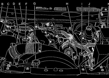
Find the positive (+) and negative (−) terminals on each battery. Your vehicle has a remote negative (−) jump starting terminal. You should always use this remote terminal instead of the terminal on the battery. The remote negative (−) terminal is located on the front engine lift bracket on vehicles with the 4.2L L6 engine or the engine accessory drive bracket for vehicles with the 5.3L or 6.0L V8 engines, and is marked GND (Ground). See Engine Compartment Overview on page 392 for more information on location.
430
{CAUTION:
Using a match near a battery can cause battery gas to explode. People have been hurt doing this, and some have been blinded. Use a flashlight if you need more light. Be sure the battery has enough water. You do not need to add water to the battery installed in your new vehicle. But if a battery has filler caps, be sure the right amount of fluid is there. If it is low, add water to take care of that first. If you do not, explosive gas could be present. Battery fluid contains acid that can burn you. Do not get it on you. If you accidentally get it in your eyes or on your skin, flush the place with water and get medical help immediately.
{CAUTION:
Fans or other moving engine parts can injure you badly. Keep your hands away from moving parts once the engine is running.
5. Check that the jumper cables do not have loose or missing insulation. If they do, you could get a shock. The vehicles could be damaged too. Before you connect the cables, here are some basic things you should know. Positive (+) will go to positive (+) or to a remote positive (+) terminal if the vehicle has one. Negative (−) will go to a heavy, unpainted metal engine part or to a remote negative (−) terminal if the vehicle has one. Do not connect positive (+) to negative (−) or you will get a short that would damage the battery and maybe other parts too. And do not connect the negative (−) cable to the negative (−) terminal on the dead battery because this can cause sparks.
6. Connect the red
positive (+) cable to the positive (+) terminal of the dead battery. Use a remote positive (+) terminal if the vehicle has one.
7. Do not let the other end touch metal. Connect
it to the positive (+) terminal of the good battery. Use a remote positive (+) terminal if the vehicle has one.
8. Now connect the black negative (−) cable to the negative (−) terminal of the good battery. Use a remote negative (−) terminal if the vehicle has one.
431
The remote negative (−) terminal is located on the front engine lift bracket for the 4.2L L6
engine, and on the accessory drive bracket for the 5.3L or 6.0L V8 engines.9. Connect the other end of the negative (−) cable to the remote negative (−) terminal on the vehicle with the dead battery.
10. Now start the vehicle with the good battery
and run the engine for a while.
11. Try to start the vehicle that had the dead
battery. If it will not start after a few tries, it probably needs service.
If the jumper cables are connected or
Notice: removed in the wrong order, electrical shorting may occur and damage the vehicle. The repairs would not be covered by your warranty. Always connect and remove the jumper cables in the correct order, making sure that the cables do not touch each other or other metal.
Do not let the other end touch anything until the next step. The other end of the negative (−) cable does not go to the dead battery. It goes to a heavy, unpainted metal engine part or to the remote negative (−) terminal on the vehicle with the dead battery. Your vehicle has a remote negative (−) terminal, marked GND, for this purpose.
5.3L V8 Engine shown,
6.0L V8 Engine
similar
4.2L L6 Engine
432
To disconnect the jumper cables from both vehicles, do the following: 1. Disconnect the black negative (−) cable from
the vehicle that had the dead battery.
2. Disconnect the black negative (−) cable from
the vehicle with the good battery.
3. Disconnect the red positive (+) cable from the
vehicle with the good battery.
4. Disconnect the red positive (+) cable from the
other vehicle.
Jumper Cable Removal
A. Heavy, Unpainted Metal Engine Part or
Remote Negative (−) Terminal
B. Good Battery or Remote Positive (+) and
Remote Negative (−) Terminals
C. Dead Battery or Remote Positive (+) Terminal
433
All-Wheel Drive When to Check Lubricant It is not necessary to regularly check fluid unless you suspect there is a leak or you hear an unusual noise. A fluid loss could indicate a problem. Have it inspected and repaired. How to Check Lubricant
To get an accurate reading, the vehicle should be on a level surface.
If the level is below the bottom of the filler plug hole, located on the transfer case, you’ll need to add some lubricant. Add enough lubricant to raise the level to the bottom of the filler plug hole. Use care not to overtighten the plug. What to Use To determine what kind of lubricant to use, see Recommended Fluids and Lubricants on page 527. Rear Axle When to Check Lubricant It is not necessary to regularly check rear axle fluid unless you suspect there is a leak or you hear an unusual noise. A fluid loss could indicate a problem. Have it inspected and repaired.
434
How to Check Lubricant
To get an accurate reading, the vehicle should be on a level surface. The proper level is from 0 to 3/8 inch (0 to 10 mm) below the bottom of the filler plug hole, located on the rear axle. For vehicles equipped with the SS package, the proper level is from 0.6 inch to 1.6 inches (15 mm to 40 mm) below the bottom of the filler plug hole, located on the rear axle. Add only enough fluid to reach the proper level.
What to Use To determine what kind of lubricant to use, see Recommended Fluids and Lubricants on page 527. For vehicles equipped with the SS package, to add lubricant when the level is low, use SAE 75W–90 Synthetic Axle Lubricant (GM Part No. U.S. 12378261, in Canada 10953455) meeting GM Specification 9986115. To completely refill after draining, add 4 ounces (118 ml) of Limited-Slip Axle Lubricant Additive (GM Part No. U.S. 1052358, in Canada 992694). Then fill to the bottom of the filler plug hole with the Synthetic Gear Lubricant. Four-Wheel Drive Transfer Case When to Check Lubricant It is not necessary to regularly check fluid unless you suspect there is a leak or you hear an unusual noise. A fluid loss could indicate a problem. Have it inspected and repaired.
435
How to Check Lubricant
To get an accurate reading, the vehicle should be on a level surface.
Front Axle When to Check Lubricant It is not necessary to regularly check front axle fluid unless you suspect there is a leak or you hear an unusual noise. A fluid loss could indicate a problem. Have it inspected and repaired. How to Check Lubricant
If the level is below the bottom of the filler plug hole, you’ll need to add some lubricant. Add enough lubricant to raise the level to the bottom of the filler plug hole. Use care not to overtighten the plug. What to Use To determine what kind of lubricant to use, see Recommended Fluids and Lubricants on page 527.
436
To get an accurate reading, the vehicle should be on a level surface.
If the level is below the bottom of the filler plug hole, located on the front axle, you may need to add some lubricant. When the differential is cold, add enough lubricant to raise the level to 1/2 inch (12 mm) below the filler plug hole. When the differential is at operating temperature (warm), add enough lubricant to raise the level to the bottom of the filler plug hole. What to Use To determine what kind of lubricant to use, see Recommended Fluids and Lubricants on page 527.
Bulb Replacement For the proper type of replacement bulbs, see Replacement Bulbs on page 439. For any bulb changing procedure not listed in this section, contact your dealer.
Halogen Bulbs
{CAUTION:
Halogen bulbs have pressurized gas inside and can burst if you drop or scratch the bulb. You or others could be injured. Be sure to read and follow the instructions on the bulb package.
437
Taillamps and Turn Signal Lamps 1. Open the liftgate. See Liftgate/Liftglass
on page 106 for more information.
2. Remove the two screws from the taillamp assembly.
3. Pull the taillamp assembly away from
the vehicle.
438
4. Unclip the wiring harness (A) and remove the three retaining screws (B) from the socket plate.
5. Remove the socket plate. 6. Holding the socket, pull the bulb to release
it from the socket.
7. Push the new bulb into the socket until it clicks. 8. Reinstall the socket and tighten the
three screws.
9. Reconnect the wiring harness. 10. Reinstall the taillamp assembly by lining up
the locator pins with the retainers in the vehicle’s body.
11. Reinstall the two screws and tighten. 12. Close the liftgate.
License Plate Lamp To replace one of these bulbs, do the following: 1. Remove the two screws holding the
license plate lamp lens.
4. Install the new bulb. 5. Replace the lamp assembly lens and tighten
the screws.
Replacement Bulbs
Exterior Lamp
Bulb Number
License Plate Lamp
Taillamps
W5W
3157
For replacement bulbs not listed here, contact your dealer.
2. Pull the lens away from the lamp assembly. 3. Pull the old bulb straight out from the
bulb socket.
439
Windshield Wiper Blade Replacement Windshield wiper blades should be inspected for wear or cracking. See Scheduled Maintenance on page 517. Allowing the wiper blade arm to touch the windshield when no wiper blade is installed could damage the windshield. Any damage that occurs would not be covered by your warranty. Do not allow the wiper blade arm to touch the windshield. 1. To remove the old wiper blades, lift the wiper
arm until it locks into a vertical position.
440
A. Blade Assembly B. Arm Assembly C. Locking Tab
D. Blade Pivot E. Hook Slot F. Arm Hook
2. Press down on the blade assembly pivot
locking tab. Pull down on the blade assembly to release it from the wiper arm hook.
3. Remove the insert from the blade assembly.
The insert has two notches at one end that are locked by the bottom claws of the blade assembly. At the notched end, pull the insert from the blade assembly.
5. Be sure that the notches are locked by the
bottom claws. Make sure that all other claws are properly locked on both sides of the insert slots.
4. To install the new wiper insert, slide the insert (D), notched end last, into the end with two blade claws (A). Slide the insert all the way through the blade claws at the opposite end (B). The plastic caps (C) will be forced off as the insert is fully inserted.
A. Claw in Notch B. Correct Installation C. Incorrect Installation
6. Put the blade assembly pivot in the wiper arm
hook. Pull up until the pivot locking tab locks in the hook slot.
7. Carefully lower the wiper arm and blade
assembly onto the windshield.
441
Backglass Wiper Blade Replacement
1. Lift the wiper blade assembly up and out of
the park rest position.
2. Pull the wiper blade assembly away from the backglass. The backglass wiper blade will not lock in a vertical position, so care should be used when pulling it away from the vehicle.
3. Rotate the wiper blade assembly, and pull it
off of the wiper arm. Hold the wiper arm in position and push the blade away from the wiper arm.
442
4. Replace the wiper blade. 5. Return the wiper blade assembly to the park
rest position.
Tires Your new vehicle comes with high-quality tires made by a leading tire manufacturer. If you ever have questions about your tire warranty and where to obtain service, see your GM Warranty booklet for details. For additional information refer to the tire manufacturer’s booklet included with your vehicle.
{CAUTION:
(cid:127) Poorly maintained and improperly
used tires are dangerous.
(cid:127) Overloading your tires can cause
overheating as a result of too much friction. You could have an air-out and a serious accident. See Loading Your Vehicle on page 350.
CAUTION:
(Continued)
CAUTION:
(Continued)
(cid:127) Underinflated tires pose the same
danger as overloaded tires. The resulting accident could cause serious injury. Check all tires frequently to maintain the recommended pressure. Tire pressure should be checked when your tires are cold. See Inflation - Tire Pressure on page 452.
(cid:127) Over inflated tires are more likely to
be cut, punctured, or broken by a sudden impact — such as when you hit a pothole. Keep tires at the recommended pressure.
(cid:127) Worn, old tires can cause accidents.
If your tread is badly worn, or if your tires have been damaged, replace them.
See High-Speed Operation on page 454
for inflation pressure adjustment for high speed driving.443
Low-Profile Performance Tire (Trailblazer SS) If your vehicle has P255/50R20 size tires, they are classified as low-profile performance tires. These tires are designed for very responsive driving on wet or dry pavement. You may also notice more road noise with low-profile performance tires and that they tend to wear faster. Notice: they are more susceptible to damage from road hazards or curb impact than standard profile tires. Tire and/or wheel assembly damage can occur when coming into contact with road hazards like, potholes, or sharp edged objects, or when sliding into a curb. Your GM warranty does not cover this type of damage. Keep tires set to the correct inflation pressure and, when possible avoid contact with curbs, potholes, and other road hazards.
If your vehicle has low-profile tires,
Winter Tires For cold weather driving conditions you may prefer to get tires designed for snow or ice, if your vehicle has P255/50R20 size tires. See your dealer for details regarding winter tire availability and proper tire selection. Also, see Buying New Tires on page 462. If you choose to use winter tires: (cid:127) Use tires of the same brand and tread type on
all four wheel positions.
(cid:127) Use only radial ply tires of the same size, load
range, and speed rating as your original equipment tires.
Winter tires with the same speed rating as your original equipment tires may not be available for H, V, W, Y and ZR speed rated tires. If you choose winter tires with a lower speed rating, never exceed the tire’s maximum speed capability.
444
Tire Sidewall Labeling Useful information about a tire is molded into the sidewall. The following illustrations are examples of a typical P-Metric and a LT-Metric tire sidewall.
Passenger (P-Metric) Tire
(A) Tire Size: The tire size code is a combination of letters and numbers used to define a particular tire’s width, height, aspect ratio, construction type, and service description. See the “Tire Size” illustration later in this section for more detail.
(B) TPC Spec (Tire Performance Criteria Specification): Original equipment tires designed to GM’s specific tire performance criteria have a TPC specification code molded onto the sidewall. GM’s TPC specifications meet or exceed all federal safety guidelines.
(C) DOT (Department of Transportation): The Department of Transportation (DOT) code indicates that the tire is in compliance with the U.S. Department of Transportation Motor Vehicle Safety Standards.
(D) Tire Identification Number (TIN): The letters and numbers following DOT code are the Tire Identification Number (TIN). The TIN shows the manufacturer and plant code, tire size, and date the tire was manufactured. The TIN is molded onto both sides of the tire, although only one side may have the date of manufacture.
445
(E) Tire Ply Material: The type of cord and number of plies in the sidewall and under the tread.
(F) Uniform Tire Quality Grading (UTQG): Tire manufacturers are required to grade tires based on three performance factors: treadwear, traction, and temperature resistance. For more information, see Uniform Tire Quality Grading on page 465.
(G) Maximum Cold Inflation Load Limit: Maximum load that can be carried and the maximum pressure needed to support that load. For information on recommended tire pressure see Inflation - Tire Pressure on page 452
and Loading Your Vehicle on page 350.446
Light Truck (LT-Metric) Tire
(A) Tire Size: The tire size code is a combination of letters and numbers used to define a particular tire’s width, height, aspect ratio, construction type, and service description. See the “Tire Size” illustration later in this section for more detail.
(B) TPC Spec (Tire Performance Criteria Specification): Original equipment tires designed to GM’s specific tire performance criteria have a TPC specification code molded onto the sidewall. GM’s TPC specifications meet or exceed all federal safety guidelines.
(C) Dual Tire Maximum Load: Maximum load that can be carried and the maximum pressure needed to support that load when used in a dual configuration. For information on recommended tire pressure see Inflation - Tire Pressure on page 452 and Loading Your Vehicle on page 350.
(D) DOT (Department of Transportation): The Department of Transportation (DOT) code indicates that the tire is in compliance with the U.S. Department of Transportation Motor Vehicle Safety Standards.
(E) Tire Identification Number (TIN): The letters and numbers following DOT code are the Tire Identification Number (TIN). The TIN shows the manufacturer and plant code, tire size, and date the tire was manufactured. The TIN is molded onto both sides of the tire, although only one side may have the date of manufacture.
(F) Tire Ply Material: The type of cord and number of plies in the sidewall and under the tread.
(G) Single Tire Maximum Load: Maximum load that can be carried and the maximum pressure needed to support that load when used as a single. For information on recommended tire pressure see Inflation - Tire Pressure on page 452 and Loading Your Vehicle on page 350.
447
Tire Size The following examples show the different parts of a tire size.
Passenger (P-Metric) Tire
Light Truck (LT-Metric) Tire
448
(A) Passenger (P-Metric) Tire: The United States version of a metric tire sizing system. The letter P as the first character in the tire size means a passenger vehicle tire engineered to standards set by the U.S. Tire and Rim Association.
(A) Light Truck (LT-Metric) Tire: The United States version of a metric tire sizing system. The letters LT as the first two characters in the tire size means a light truck tire engineered to standards set by the U.S. Tire and Rim Association. (B) Tire Width: The three-digit number indicates the tire section width in millimeters from sidewall to sidewall. (C) Aspect Ratio: A two-digit number that indicates the tire height-to-width measurements. For example, if the tire size aspect ratio is 75, as shown in item C of the light truck (LT-Metric) tire illustration, it would mean that the tire’s sidewall is 75 percent as high as it is wide. (D) Construction Code: A letter code is used to indicate the type of ply construction in the tire. The letter R means radial ply construction; the letter D means diagonal or bias ply construction; and the letter B means belted-bias ply construction.
(E) Rim Diameter: Diameter of the wheel in inches. (F) Service Description: The service description indicates the load range and speed rating of a tire. The load index can range from 1 to 279. Speed ratings range from A to Z.
Tire Terminology and Definitions
Air Pressure: The amount of air inside the tire pressing outward on each square inch of the tire. Air pressure is expressed in pounds per square inch (psi) or kilopascal (kPa).
Accessory Weight: This means the combined weight of optional accessories. Some examples of optional accessories are, automatic transmission/transaxle, power steering, power brakes, power windows, power seats, and air conditioning.
Aspect Ratio: The relationship of a tire’s height to its width.
Belt: A rubber coated layer of cords that is located between the plies and the tread. Cords may be made from steel or other reinforcing materials.
Bead: The tire bead contains steel wires wrapped by steel cords that hold the tire onto the rim.
Bias Ply Tire: A pneumatic tire in which the plies are laid at alternate angles less than 90 degrees to the centerline of the tread.
Cold Tire Pressure: The amount of air pressure in a tire, measured in pounds per square inch (psi) or kilopascals (kPa) before a tire has built up heat from driving. See Inflation - Tire Pressure on page 452.
Curb Weight: This means the weight of a motor vehicle with standard and optional equipment including the maximum capacity of fuel, oil, and coolant, but without passengers and cargo.
449
DOT Markings: A code molded into the sidewall of a tire signifying that the tire is in compliance with the U.S. Department of Transportation (DOT) motor vehicle safety standards. The DOT code includes the Tire Identification Number (TIN), an alphanumeric designator which can also identify the tire manufacturer, production plant, brand, and date of production.
GVWR: Gross Vehicle Weight Rating. See Loading Your Vehicle on page 350.
GAWR FRT: Gross Axle Weight Rating for the front axle. See Loading Your Vehicle on page 350.
GAWR RR: Gross Axle Weight Rating for the rear axle. See Loading Your Vehicle on page 350.
Intended Outboard Sidewall: The side of an asymmetrical tire, that must always face outward when mounted on a vehicle.
Kilopascal (kPa): The metric unit for air pressure.
Light Truck (LT-Metric) Tire: A tire used on light duty trucks and some multipurpose passenger vehicles.
Load Index: An assigned number ranging from 1 to 279 that corresponds to the load carrying capacity of a tire.
Maximum Inflation Pressure: The maximum air pressure to which a cold tire may be inflated. The maximum air pressure is molded onto the sidewall.
Maximum Load Rating: The load rating for a tire at the maximum permissible inflation pressure for that tire.
Maximum Loaded Vehicle Weight: The sum of curb weight, accessory weight, vehicle capacity weight, and production options weight.
Normal Occupant Weight: The number of occupants a vehicle is designed to seat multiplied by 150 lbs (68 kg). See Loading Your Vehicle on page 350.
450
Occupant Distribution: Designated seating positions.
Outward Facing Sidewall: The side of an asymmetrical tire that has a particular side that faces outward when mounted on a vehicle. The side of the tire that contains a whitewall, bears white lettering, or bears manufacturer, brand, and/or model name molding that is higher or deeper than the same moldings on the other sidewall of the tire.
Passenger (P-Metric) Tire: A tire used on passenger cars and some light duty trucks and multipurpose vehicles.
Recommended Inflation Pressure: Vehicle manufacturer’s recommended tire inflation pressure as shown on the tire placard. See Inflation - Tire Pressure on page 452 and Loading Your Vehicle on page 350.
Radial Ply Tire: A pneumatic tire in which the ply cords that extend to the beads are laid at 90 degrees to the centerline of the tread.
Rim: A metal support for a tire and upon which the tire beads are seated.
Sidewall: The portion of a tire between the tread and the bead.
Speed Rating: An alphanumeric code assigned to a tire indicating the maximum speed at which a tire can operate.
Traction: The friction between the tire and the road surface. The amount of grip provided.
Tread: The portion of a tire that comes into contact with the road.
Treadwear Indicators: Narrow bands, sometimes called wear bars, that show across the tread of a tire when only 1/16 inch (1.6 mm) of tread remains. See When It Is Time for New Tires on page 462.
451
UTQGS (Uniform Tire Quality Grading Standards): A tire information system that provides consumers with ratings for a tire’s traction, temperature, and treadwear. Ratings are determined by tire manufacturers using government testing procedures. The ratings are molded into the sidewall of the tire. See Uniform Tire Quality Grading on page 465.
Vehicle Capacity Weight: The number of designated seating positions multiplied by 150 lbs (68 kg) plus the rated cargo load. See Loading Your Vehicle on page 350.
Vehicle Maximum Load on the Tire: Load on an individual tire due to curb weight, accessory weight, occupant weight, and cargo weight.
Vehicle Placard: A label permanently attached to a vehicle showing the vehicle’s capacity weight and the original equipment tire size and recommended inflation pressure. See “Tire and Loading Information Label” under Loading Your Vehicle on page 350.
Inflation - Tire Pressure Tires need the correct amount of air pressure to operate effectively. Notice: Do not let anyone tell you that under-inflation or over-inflation is all right. It is not. If your tires do not have enough air (under-inflation), you can get the following: (cid:127) Too much flexing (cid:127) Too much heat (cid:127) Tire overloading (cid:127) Premature or irregular wear (cid:127) Poor handling (cid:127) Reduced fuel economy If your tires have too much air (over-inflation), you can get the following: (cid:127) Unusual wear (cid:127) Poor handling (cid:127) Rough ride (cid:127) Needless damage from road hazards
452
A Tire and Loading Information label is attached to the vehicle’s center pillar (B-pillar), below the driver’s door latch. This label shows your vehicle’s original equipment tires and the correct inflation pressures for your tires when they are cold. The recommended cold tire inflation pressure, shown on the label, is the minimum amount of air pressure needed to support your vehicle’s maximum load carrying capacity. For additional information regarding how much weight your vehicle can carry, and an example of the tire and loading information label, see Loading Your Vehicle on page 350. How you load your vehicle affects vehicle handling and ride comfort, never load your vehicle with more weight than it was designed to carry. When to Check Check your tires once a month or more. Also, check the tire pressure of the spare tire.
How to Check Use a good quality pocket-type gage to check tire pressure. You cannot tell if your tires are properly inflated simply by looking at them. Radial tires may look properly inflated even when they’re underinflated. Check the tire’s inflation pressure when the tires are cold. Cold means your vehicle has been sitting for at least three hours or driven no more than 1 mile (1.6 km). Remove the valve cap from the tire valve stem. Press the tire gage firmly onto the valve to get a pressure measurement. If the cold tire inflation pressure matches the recommended pressure on the tire and loading information label, no further adjustment is necessary. If the pressure is low, add air until you reach the recommended amount. If you overfill the tire, release air by pushing on the metal stem in the center of the tire valve. Recheck the tire pressure with the tire gage. Be sure to put the valve caps back on the valve stems. They help prevent leaks by keeping out dirt and moisture.
453
High-Speed Operation
{CAUTION:
Driving at high speeds, 100 mph (160 km/h) or higher, puts an additional strain on tires. Sustained high-speed driving causes excessive heat build up and can cause sudden tire failure. You could have a crash and you or others could be killed. Some high-speed rated tires require inflation pressure adjustment for high speed operation. When speed limits and road conditions are such that a vehicle can be driven at high speeds, make sure the tires are rated for high speed operation, in excellent condition, and set to the correct cold tire inflation pressure for the vehicle load.
If your vehicle has P255/50R20 104V size tires installed on the rear axle, they will require inflation pressure adjustment when driving your vehicle at speeds above 99 mph (160 km/h). Set the cold inflation pressure, for the rear tires only, to the maximum inflation pressure shown on the tire sidewall, or 38 psi (262 kPa), whichever is lower. See the example following. When you end this high-speed driving, return the tires to the cold tire inflation pressure shown on the Tire and Loading Information label. See Loading Your Vehicle on page 350. Example: You will find the maximum load and inflation pressure molded on the tire’s sidewall, in small letters, near the rim flange. It will read something like this: Maximum load 690 kg (1521 lbs) 300 kPa (44 psi) Max. Press.
454
For this example, you would set the inflation pressure for high-speed driving at 38 psi (262 kPa). The inflation pressure for the front tires should be set to the cold tire inflation pressure shown on the Tire and Loading Information label. Racing or other competitive driving may affect the warranty coverage of your vehicle. See your warranty booklet for more information.
Tire Pressure Monitor System The Tire Pressure Monitor System (TPMS) uses radio and sensor technology to check tire pressure levels. TPMS sensors are mounted on each tire and wheel assembly, except the spare tire. The TPMS sensors monitor the air pressure in your vehicle’s tires and transmit tire pressure readings to a receiver located in the vehicle.
The TPMS is designed to alert the driver if a low tire pressure condition exists. If your vehicle has the Driver Information Center (DIC) steering wheel control buttons, tire pressure levels may also be checked through the DIC. See “Tire Pressures” under DIC Operation and Displays on page 217. When a low tire pressure condition is detected, the TPMS will illuminate the low tire pressure warning symbol located on the instrument panel cluster, and at the same time a message will also appear on the DIC display. The low tire pressure warning symbol on the instrument panel cluster and the CHECK TIRE PRESSURE warning message on the DIC will appear at each ignition cycle until the tires are inflated to the correct inflation pressure.
455
For additional information and details about the DIC operation and displays see DIC Operation and Displays on page 217 and DIC Warnings and Messages on page 220. You may notice, during cooler weather conditions, that the tire pressure monitor light, located on the instrument panel cluster, and the CHECK TIRE PRESSURE message will appear when the vehicle is first started, and then turn off as you start to drive the vehicle. This could be an early indicator that the tire pressures are getting low and need to be inflated to the proper pressure. Each tire, including the spare (if provided), should be checked monthly when cold and inflated to the inflation pressure recommended by the vehicle manufacturer on the vehicle placard or tire inflation pressure label. (If your vehicle has tires of a different size than the size indicated on the vehicle placard or tire inflation pressure label, you should determine the proper tire inflation pressure for those tires.)
456
As an added safety feature, your vehicle has been equipped with a tire pressure monitoring system (TPMS) that illuminates a low tire pressure telltale when one or more of your tires is significantly under-inflated.
Accordingly, when the low tire pressure telltale illuminates, you should stop and check your tires as soon as possible, and inflate them to the proper pressure. Driving on a significantly under-inflated tire causes the tire to overheat and can lead to tire failure. Under-inflation also reduces fuel efficiency and tire tread life, and may affect the vehicle’s handling and stopping ability. Please note that the TPMS is not a substitute for proper tire maintenance, and it is the driver’s responsibility to maintain correct tire pressure, even if under-inflation has not reached the level to trigger illumination of the TPMS low tire pressure telltale.
Your vehicle has also been equipped with a TPMS malfunction indicator to indicate when the system is not operating properly. The TPMS malfunction indicator is combined with the low tire pressure telltale. When the system detects a malfunction, the telltale will flash for approximately one minute and then remain continuously illuminated. This sequence will continue upon subsequent vehicle start-ups as long as the malfunction exists. When the malfunction indicator is illuminated, the system may not be able to detect or signal low tire pressure as intended. TPMS malfunctions may occur for a variety of reasons, including the installation of replacement or alternate tires or wheels on the vehicle that prevent the TPMS from functioning properly. Always check the TPMS malfunction telltale after replacing one or more tires or wheels on your vehicle to ensure that the replacement or alternate tires and wheels allow the TPMS to continue to function properly.
The Tire and Loading Information label (tire information placard) shows the size of your vehicle’s original tires and the correct inflation pressure for your vehicle’s tires when they are cold. See Inflation - Tire Pressure on page 452. For the location of the tire and loading information label, see Loading Your Vehicle on page 350. Your vehicle’s TPMS can alert you about a low tire pressure condition but it does not replace normal tire maintenance. See Tire Inspection and Rotation on page 460 and Tires on page 443. Notice: Do not use a tire sealant if your vehicle has Tire Pressure Monitors. The liquid sealant can damage the tire pressure monitor sensors.
457
The TPMS sensor matching process is outlined below: 1. Set the parking brake. 2. Turn the ignition switch to RUN with the
engine off.
3. Turn the headlamp control from off to parking
lamps four times within three seconds. A double horn chirp will sound and the TPMS low tire warning light will begin to flash. The double horn chirp and flashing TPMS warning light indicate that the TPMS matching process has started. The TPMS warning light should continue flashing throughout the matching procedure.
4. Start with the driver’s side front tire.
TPMS Sensor Identification Codes Each TPMS sensor has a unique identification code. Any time you replace one or more of the TPMS sensors or rotate the vehicle’s tires, the identification codes will need to be matched to the new tire/wheel position. The sensors are matched to the tire/wheel positions in the following order: driver’s side front tire, passenger’s side front tire, passenger’s side rear tire, and driver’s side rear tire using a TPMS diagnostic tool. See your dealer for service. The TPMS sensors may also be matched to each tire/wheel position by increasing or decreasing the tire’s air pressure. When increasing the tire’s pressure, do not exceed the maximum inflation pressure indicated on the tire’s sidewall. You will have two minutes to match the first tire/wheel position, and five minutes overall to match all four tire/wheel positions. If it takes longer than two minutes, to match the first tire and wheel, or more than five minutes to match all four tire and wheel positions the matching process stops and you will need to start over.
458
5. Remove the valve cap from the valve cap
stem. Activate the TPMS sensor by increasing or decreasing the tire’s air pressure for 10 seconds, then stop and listen for a single horn chirp. The single horn chirp should sound within 15 seconds, confirming that the sensor identification code has been matched to this tire and wheel position. If you do not hear the confirming single horn chirp, you will need to start over with step number one. To let air-pressure out of a tire you can use the pointed end of the valve cap, a pencil-style air pressure gage, or a key. 6. Proceed to the passenger’s side front tire,
and repeat the procedure in Step 5.
7. Proceed to the passenger’s side rear tire,
and repeat the procedure in Step 5.
8. Proceed to the driver’s side rear tire, and
repeat the procedure in Step 5.
9. After hearing the confirming horn chirp for the driver’s side rear tire, check to see if the TPMS warning light is still flashing. If yes, turn the ignition switch to LOCK to exit the sensor matching process. If the TPMS warning light is not flashing, the five minute time limit has passed and you will need to start the process over beginning with Step 1.
10. Set all four tires to the recommended air
pressure level as indicated on the Tire and Loading Information label.
11. Put the valve caps back on the valve stems The spare tire does not have a TPMS sensor. If you replace one of the road tires with the spare, the SERVICE TIRE MONITOR message will be displayed on the DIC screen. This message should go off once you re-install the road tire containing the TPMS sensor.
459
Tire Inspection and Rotation Tires should be rotated every 5,000 to 8,000 miles (8 000 to 13 000 km). Any time you notice unusual wear, rotate your tires as soon as possible and check wheel alignment. Also check for damaged tires or wheels. See When It Is Time for New Tires on page 462
and Wheel Replacement on page 467 for more information. Make sure the spare tire is stored securely. Push, pull, and then try to rotate or turn the tire. If it moves, use the wheel wrench to tighten the cable. For information on storing or removing the spare tire, see Changing a Flat Tire on page 472. The purpose of regular rotation is to achieve more uniform wear for all tires on the vehicle. The first rotation is the most important. See Scheduled Maintenance on page 517.Federal Communications Commission (FCC) and Industry and Science Canada The Tire Pressure Monitor System (TPMS) operates on a radio frequency and complies with Part 15 of the FCC Rules. Operation is subject to the following two conditions: 1. This device may not cause harmful
interference.
2. This device must accept any interference received, including interference that may cause undesired operation.
The Tire Pressure Monitor System (TPMS) operates on a radio frequency and complies with RSS-210 of Industry and Science Canada. Operation is subject to the following two conditions: 1. This device may not cause interference. 2. This device must accept any interference received, including interference that may cause undesired operation of the device.
Changes or modifications to this system by other than an authorized service facility could void authorization to use this equipment.
460
When rotating your tires, always use the correct rotation pattern shown here. After the tires have been rotated, adjust the front and rear inflation pressures as shown on the Tire and Loading Information label. See Loading Your Vehicle on page 350, for an example of the label and its location on your vehicle. The Tire Pressure Monitor System (TPMS) sensors will need to be reset after a tire rotation. See “TPMS Sensor Identification Codes” under Tire Pressure Monitor System on page 455.
Make certain that all wheel nuts are properly tightened. See “Wheel Nut Torque” under Capacities and Specifications on page 510.
{CAUTION:
Rust or dirt on a wheel, or on the parts to which it is fastened, can make wheel nuts become loose after time. The wheel could come off and cause an accident. When you change a wheel, remove any rust or dirt from places where the wheel attaches to the vehicle. In an emergency, you can use a cloth or a paper towel to do this; but be sure to use a scraper or wire brush later, if needed, to get all the rust or dirt off. See Changing a Flat Tire on page 472.
461
When It Is Time for New Tires
One way to tell when it is time for new tires is to check the treadwear indicators, which will appear when your tires have only 1/16 inch (1.6 mm) or less of tread remaining. Some commercial truck tires may not have treadwear indicators.
You need a new tire if any of the following statements are true: (cid:127) You can see the indicators at three or more
places around the tire.
(cid:127) You can see cord or fabric showing through
the tire’s rubber.
(cid:127) The tread or sidewall is cracked, cut or
snagged deep enough to show cord or fabric.
(cid:127) The tire has a bump, bulge, or split. (cid:127) The tire has a puncture, cut, or other damage
that cannot be repaired well because of the size or location of the damage.
462
Buying New Tires GM has developed and matched specific tires for your vehicle. The original equipment tires installed on your vehicle, when it was new, were designed to meet General Motors Tire Performance Criteria Specification (TPC spec) system rating. If you need replacement tires, GM strongly recommends that you get tires with the same TPC Spec rating. This way, your vehicle will continue to have tires that are designed to give the same performance and vehicle safety, during normal use, as the original tires. GM’s exclusive TPC Spec system considers over a dozen critical specifications that impact the overall performance of your vehicle, including brake system performance, ride and handling, traction control, and tire pressure monitoring performance. GM’s TPC Spec number is molded onto the tire’s sidewall by the tire manufacturer. If the tires have an all-season tread design, the TPC spec number will be followed by a MS, for mud and snow. See Tire Sidewall Labeling on page 445 for additional information.
{CAUTION:
{CAUTION:
Mixing tires could cause you to lose control while driving. If you mix tires of different sizes, brands, or types (radial and bias-belted tires) the vehicle may not handle properly, and you could have a crash. Using tires of different sizes, brands, or types may also cause damage to your vehicle. Be sure to use the correct size, brand, and type of tires on your vehicle’s wheels.
If you use bias-ply tires on your vehicle, the wheel rim flanges could develop cracks after many miles of driving. A tire and/or wheel could fail suddenly, causing a crash. Use only radial-ply tires with the wheels on your vehicle.
If you must replace your vehicle’s tires with those that do not have a TPC Spec number, make sure they are the same size, load range, speed rating, and construction type (radial and bias-belted tires) as your vehicle’s original tires. Vehicles equipped with a tire pressure monitoring system may give an inaccurate low-pressure warning if non-TPC spec rated tires are installed on your vehicle. Non-TPC Spec rated tires may give a low-pressure warning that is higher or lower than the proper warning level you would get with TPC Spec rated tires. See Tire Pressure Monitor System on page 455.
463
Your vehicle’s original equipment tires are listed on the Tire and Loading Information Label. This label is attached to the vehicle’s center pillar (B-pillar). See Loading Your Vehicle on page 350, for more information about the Tire and Loading Information Label.
Different Size Tires and Wheels If you add wheels or tires that are a different size than your original equipment wheels and tires, this may affect the way your vehicle performs, including its braking, ride and handling characteristics, stability, and resistance to rollover. Additionally, if your vehicle has electronic systems such as, anti-lock brakes, traction control, and electronic stability control, the performance of these systems can be affected.
{CAUTION:
If you add different sized wheels, your vehicle may not provide an acceptable level of performance and safety if tires not recommended for those wheels are selected. You may increase the chance that you will crash and suffer serious injury. Only use GM specific wheel and tire systems developed for your vehicle, and have them properly installed by a GM certified technician.
See Buying New Tires on page 462 and Accessories and Modifications on page 382 for additional information.
464
Uniform Tire Quality Grading Quality grades can be found where applicable on the tire sidewall between tread shoulder and maximum section width. For example: Treadwear 200 Traction AA Temperature A The following information relates to the system developed by the United States National Highway Traffic Safety Administration (NHTSA), which grades tires by treadwear, traction, and temperature performance. This applies only to vehicles sold in the United States. The grades are molded on the sidewalls of most passenger car tires. The Uniform Tire Quality Grading (UTQG) system does not apply to deep tread, winter-type snow tires, space-saver, or temporary use spare tires, tires with nominal rim diameters of 10 to 12 inches (25 to 30 cm), or to some limited-production tires. While the tires available on General Motors passenger cars and light trucks may vary with respect to these grades, they must also conform to federal safety requirements and additional General Motors Tire Performance Criteria (TPC) standards.
Treadwear The treadwear grade is a comparative rating based on the wear rate of the tire when tested under controlled conditions on a specified government test course. For example, a tire graded 150 would wear one and a half (1.5) times as well on the government course as a tire graded 100. The relative performance of tires depends upon the actual conditions of their use, however, and may depart significantly from the norm due to variations in driving habits, service practices, and differences in road characteristics and climate. Traction – AA, A, B, C The traction grades, from highest to lowest, are AA, A, B, and C. Those grades represent the tire’s ability to stop on wet pavement as measured under controlled conditions on specified government test surfaces of asphalt and concrete. A tire marked C may have poor traction performance. Warning: The traction grade assigned to this tire is based on straight-ahead braking traction tests, and does not include acceleration, cornering, hydroplaning, or peak traction characteristics.
465
Wheel Alignment and Tire Balance The tires and wheels on your vehicle were aligned and balanced carefully at the factory to give you the longest tire life and best overall performance. Adjustments to wheel alignment and tire balancing will not be necessary on a regular basis. However, if you notice unusual tire wear or your vehicle pulling to one side or the other, the alignment may need to be checked. If you notice your vehicle vibrating when driving on a smooth road, your tires and wheels may need to be rebalanced. See your dealer for proper diagnosis.
Temperature – A, B, C The temperature grades are A (the highest), B, and C, representing the tire’s resistance to the generation of heat and its ability to dissipate heat when tested under controlled conditions on a specified indoor laboratory test wheel. Sustained high temperature can cause the material of the tire to degenerate and reduce tire life, and excessive temperature can lead to sudden tire failure. The grade C corresponds to a level of performance which all passenger car tires must meet under the Federal Motor Vehicle Safety Standard No. 109. Grades B and A represent higher levels of performance on the laboratory test wheel than the minimum required by law. Warning: The temperature grade for this tire is established for a tire that is properly inflated and not overloaded. Excessive speed, underinflation, or excessive loading, either separately or in combination, can cause heat buildup and possible tire failure.
466
Wheel Replacement Replace any wheel that is bent, cracked, or badly rusted or corroded. If wheel nuts keep coming loose, the wheel, wheel bolts, and wheel nuts should be replaced. If the wheel leaks air, replace it (except some aluminum wheels, which can sometimes be repaired). See your dealer if any of these conditions exist. Your dealer will know the kind of wheel you need. Each new wheel should have the same load-carrying capacity, diameter, width, offset and be mounted the same way as the one it replaces. If you need to replace any of your wheels, wheel bolts, or wheel nuts, replace them only with new GM original equipment parts. This way, you will be sure to have the right wheel, wheel bolts, and wheel nuts for your vehicle.
{CAUTION:
Using the wrong replacement wheels, wheel bolts, or wheel nuts on your vehicle can be dangerous. It could affect the braking and handling of your vehicle, make your tires lose air and make you lose control. You could have a collision in which you or others could be injured. Always use the correct wheel, wheel bolts, and wheel nuts for replacement.
Notice: The wrong wheel can also cause problems with bearing life, brake cooling, speedometer or odometer calibration, headlamp aim, bumper height, vehicle ground clearance, and tire or tire chain clearance to the body and chassis. See Changing a Flat Tire on page 472 for more information.
467
Used Replacement Wheels
Tire Chains
{CAUTION:
{CAUTION:
Putting a used wheel on your vehicle is dangerous. You cannot know how it has been used or how far it has been driven. It could fail suddenly and cause a crash. If you have to replace a wheel, use a new GM original equipment wheel.
468
Do not use tire chains. There is not enough clearance. Tire chains used on a vehicle without the proper amount of clearance can cause damage to the brakes, suspension, or other vehicle parts. The area damaged by the tire chains could cause you to lose control of your vehicle and you or others may be injured in a crash. Use another type of traction device only if its manufacturer recommends it for use on your vehicle and tire size combination and road conditions. Follow that manufacturer’s instructions. To help avoid damage to your vehicle, drive slowly, re-adjust or remove the device if it is contacting your vehicle, and do not spin your wheels. If you do find traction devices that will fit, install them on the rear tires.
Accessory Inflator Your vehicle may have an accessory inflator system. You can inflate things like basketballs and bicycle tires. You can also use it to bring your tire pressure up to the proper pressure. It is not designed to inflate large objects which will require more than five minutes to inflate, such as an air mattress.
The accessory inflator is located in the rear compartment on the driver’s side of the vehicle behind an access cover, near the liftgate opening.
To remove the cover, push in on the tab to access the inflator.
You may have an air inflator kit that is located in the glove compartment. It includes a 22 ft (6.7 m) hose with three nozzle adapters.
To use the accessory inflator, do the following: 1. Attach the appropriate nozzle adapter
to the end of the hose, if required.
{CAUTION:
Inflating something too much can make it explode, and you or others could be injured. Be sure to read the inflator instructions, and inflate any object only to its recommended pressure.
2. Attach that end of the hose to the object you
wish to inflate.
3. Attach the other end of the hose to the outlet.
469
4. Press and release the switch to turn the air inflator on. The indicator light will remain on when the inflator is running. The system has an internal clock to prevent the system from overheating. The system will allow about five minutes of running time, then the compressor will stop. The indicator light will then begin to flash. When the indicator is off, the inflator can be started again by pressing the switch. If the compressor is still hot, it may only run for a short time before shutting off again.
5. Press and release the switch to turn the
inflator off.
Place the inflator kit tools in the pouch and store it in its proper location. Remove the inflator hose from the outlet during loading and unloading. Load leveling will not function with the inflator hose attached to the inflator outlet. See Electronically Controlled Air Suspension System on page 361 for more information. To reinstall the cover, line up the tabs at the back of the cover, put it in place and latch the tabs. A continuous flashing indicator light may also indicate a malfunction in the air suspension system. See Electronically Controlled Air Suspension System on page 361 for more information.
470
If a Tire Goes Flat It is unusual for a tire to blowout while you are driving, especially if you maintain your vehicle’s tires properly. If air goes out of a tire, it is much more likely to leak out slowly. But if you should ever have a blowout, here are a few tips about what to expect and what to do: If a front tire fails, the flat tire will create a drag that pulls the vehicle toward that side. Take your foot off the accelerator pedal and grip the steering wheel firmly. Steer to maintain lane position, and then gently brake to a stop well out of the traffic lane. A rear blowout, particularly on a curve, acts much like a skid and may require the same correction you would use in a skid. In any rear blowout remove your foot from the accelerator pedal. Get the vehicle under control by steering the way you want the vehicle to go. It may be very bumpy and noisy, but you can still steer. Gently brake to a stop, well off the road if possible.
{CAUTION:
Lifting a vehicle and getting under it to do maintenance or repairs is dangerous without the appropriate safety equipment and training. The jack provided with your vehicle is designed only for changing a flat tire. If it is used for anything else, you or others could be badly injured or killed if the vehicle slips off the jack. Use the jack provided with your vehicle only for changing a flat tire.
If a tire goes flat, the next part shows how to use the jacking equipment to change a flat tire safely.
471
CAUTION:
(Continued)
3. If you have a four-wheel-drive vehicle,
be sure the transfer case is in a drive gear — not in NEUTRAL.
4. Turn off the engine and do not restart
while the vehicle is raised.
5. Do not allow passengers to remain in
the vehicle.
6. Put the wheel blocks at the front and rear of the tire farthest away from the one being changed. That would be the tire on the other side, at the opposite end of the vehicle.
Changing a Flat Tire If a tire goes flat, avoid further tire and wheel damage by driving slowly to a level place. Turn on your hazard warning flashers. See Hazard Warning Flashers on page 170 for more information.
{CAUTION:
Changing a tire can be dangerous. The vehicle can slip off the jack and roll over or fall on you or other people. You and they could be badly injured or even killed. Find a level place to change your tire. To help prevent the vehicle from moving: 1. Set the parking brake firmly. 2. Put the shift lever in PARK (P).
CAUTION:
(Continued)
472
When your vehicle has a flat tire, use the following example as a guide to assist you in the placement of wheel blocks.
Removing the Spare Tire and Tools
The following information will tell you how to use the jack and change a tire.
The jacking equipment needed to remove the spare tire is stored under the rear seat. To release the jack from its holder, turn the knob on the jack counterclockwise to lower the jack head. See Rear Seat Operation on page 18 for more information.
473
A. Wheel Wrench B. Hoist Shaft C. Extension D. Retainer E. Spare or Flat Tire
(Valve Stem Pointed Up)
1. Open the liftgate. See Liftgate/Liftglass on
page 106 for more information.
2. Attach the wheel wrench (A) to the
extension (C).
The tools you will be using include the wheel wrench (A), wheel blocks (B), extension(s) (socket end) (C), handle (jack end) (D), and jack (E). The following instructions explain how to remove the underbody-mounted spare underneath your vehicle. Notice: the storage position under the vehicle when it is supported by a jack, you could damage the tire and/or your vehicle. Always remove or restow a tire when the vehicle is on the ground.
If you remove or restow a tire from/to
474
3. Insert the socket
end of the extension (C) on a 45 degree angle downward into the hoist drive shaft hole.
It is exposed when the rear gate is open and is just above the rear bumper. Be sure the socket end of the extension (C) connects to the hoist shaft.
4. Turn the wheel wrench counterclockwise to lower the spare tire. Keep turning the wheel wrench until the spare tire can be pulled out from under the vehicle. If the spare tire does not lower to the ground, the secondary latch is engaged causing the tire not to lower. See Secondary Latch System on page 482 for more information.
475
If you drive away before the spare tire
6. Pull the tire out from under the vehicle. Notice: or secondary latch system cable has been reinstalled, you could damage your vehicle. Always reinstall this cable before driving your vehicle. 7. Put the spare tire near the flat tire.
5. Tilt the retainer at the end of the cable when
the tire has been completely lowered, and pull it through the wheel opening.
476
Removing the Flat Tire and Installing the Spare Tire
1. Using the wheel wrench, loosen all the wheel nuts. Do not remove them yet.
2. Turn the jack adjusting knob clockwise by
hand to raise the jack lift head.
3. Place the handle, extension and wheel
wrench onto the jack.
Front Position
Rear Position
A. Front Frame/Rear Axle B. Handle C. Extension D. Extension E. Wheel Wrench
4. Place the jack in the appropriate position
nearest the flat tire.
477
{CAUTION:
Getting under a vehicle when it is jacked up is dangerous. If the vehicle slips off the jack you could be badly injured or killed. Never get under a vehicle when it is supported only by a jack.
{CAUTION:
Raising your vehicle with the jack improperly positioned can damage the vehicle and even make the vehicle fall. To help avoid personal injury and vehicle damage, be sure to fit the jack lift head into the proper location before raising the vehicle.
478
5. Raise the vehicle by turning the jack handle clockwise. Raise the vehicle far enough off the ground so there is enough room for the spare tire to fit.
6. Remove all the
wheel nuts and take off the flat tire.
CAUTION:
(Continued)
In an emergency, you can use a cloth or a paper towel to do this; but be sure to use a scraper or wire brush later, if needed, to get all the rust or dirt off.
{CAUTION:
Rust or dirt on the wheel, or on the parts to which it is fastened, can make the wheel nuts become loose after time. The wheel could come off and cause an accident. When you change a wheel, remove any rust or dirt from the places where the wheel attaches to the vehicle.
CAUTION:
(Continued)
7. Remove any rust
or dirt from the wheel bolts, mounting surfaces and spare wheel.
8. Place the spare tire on the wheel-mounting
surface.
479
{CAUTION:
Never use oil or grease on studs or nuts. If you do, the nuts might come loose. Your wheel could fall off, causing a serious accident.
9. Put the nuts on by hand. Make sure the
rounded end is toward the wheel.
10. Tighten each nut by hand until the wheel is
held against the hub. If a nut cannot be turned by hand, use the wheel wrench and see your dealer as soon as possible.
480
11. Lower the vehicle by turning the jack handle counterclockwise. Lower the jack completely.
{CAUTION:
Incorrect wheel nuts or improperly tightened wheel nuts can cause the wheel to come loose and even come off. This could lead to an accident. Be sure to use the correct wheel nuts. If you have to replace them, be sure to get new original equipment wheel nuts. Stop somewhere as soon as you can and have the nuts tightened with a torque wrench to the proper torque specification. See Capacities and Specifications on page 510
for wheel nut torque specification.Improperly tightened wheel nuts can
Notice: lead to brake pulsation and rotor damage. To avoid expensive brake repairs, evenly tighten the wheel nuts in the proper sequence and to the proper torque specification. See Capacities and Specifications on page 510 for the wheel nut torque specification.
12. Use the wrench to tighten the wheel nuts firmly in a crisscross sequence as shown.
481
Secondary Latch System Your vehicle has an underbody-mounted tire hoist assembly equipped with a secondary latch system. It is designed to stop the spare tire from suddenly falling off your vehicle if the cable holding the spare tire is damaged. For the secondary latch to work, the tire must be stored with the valve stem pointing up. See Storing a Flat or Spare Tire and Tools on page 486 for instructions on storing the spare or flat tire correctly.
{CAUTION:
Someone standing too close during the procedure could be injured by the jack. If the spare tire does not slide off the jack completely, make sure no one is behind you or on either side of you as you pull the jack out from the spare.
{CAUTION:
To release the spare tire from the secondary latch, do the following:
Before beginning this procedure read all the instructions. Failure to read and follow the instructions could damage the hoist assembly and you and others could get hurt. Read and follow the instructions listed next.
1. Check under the vehicle to see if the cable is visible. If it is not visible, proceed to Step 6.
482
2. If visible, first try to tighten the cable by turning the wheel wrench clockwise until you hear two clicks or feel it skip twice. You cannot overtighten the cable.
3. Loosen the cable by turning the wheel wrench
counterclockwise three or four turns.
4. Repeat this procedure at least two times.
If the spare tire lowers to the ground, continue with Step 2 of Removing the Spare Tire and Tools on page 473.
5. Turn the wrench counterclockwise until approximately 6 inches (15 cm) of cable is exposed.
6. Attach the jack handle, extension(s) and the wheel wrench to the jack and place it under the vehicle towards the front of the rear bumper. Position the center lift point of the jack under the center of the spare tire.
7. Turn the wrench clockwise to raise the jack
until it lifts the end fitting.
483
8. Continue raising the jack until the spare tire
stops moving upward and is held firmly in place. The secondary latch has released and the spare tire is balancing on the jack.
9. Lower the jack by turning the wheel wrench
counterclockwise. Keep lowering the jack until the spare tire slides off the jack or is hanging by the cable.
10. Disconnect the jack handle from the jack and
carefully remove the jack. Use one hand to push against the spare while firmly pulling the jack out from under the spare tire with the other hand.
11. If the spare tire is hanging from the cable, insert the socket end of the extension into the hoist shaft hole on a 45 degree angle downward.
12. Be sure that the socket end of the extension
connects to the hoist shaft.
484
13. Tilt the retainer at the end of the cable and
pull it through the wheel opening. Pull the tire out from under the vehicle.
If you drive away before the spare tire
Notice: or secondary latch system cable has been reinstalled, you could damage your vehicle. Always reinstall this cable before driving your vehicle. 14. Turn the wheel wrench clockwise to raise the
cable back up if the cable is hanging under the vehicle.
Turn the wheel wrench counterclockwise to lower the spare the rest of the way.
Have the hoist assembly inspected as soon as you can. You will not be able to store a spare tire using the hoist assembly until it has been repaired or replaced.
485
Storing a Flat or Spare Tire and Tools
{CAUTION:
{CAUTION:
Storing a jack, a tire, or other equipment in the passenger compartment of the vehicle could cause injury. In a sudden stop or collision, loose equipment could strike someone. Store all these in the proper place.
486
The underbody-mounted spare tire needs to be stored with the valve stem pointing up. If the spare tire is stored with the valve stem pointing downward, its secondary latch will not work properly and the spare tire could loosen and suddenly fall from your vehicle. If this happened when your vehicle was being driven, the tire might contact a person or another vehicle, causing injury and, of course, damage to itself as well. Be sure the underbody-mounted spare tire is stored with its valve stem pointing up.
Notice: An aluminum wheel with a flat tire should always be stored under the vehicle with the hoist. However, storing it that way for an extended period could damage the wheel. To avoid this, always stow the wheel properly with the valve stem pointing up and have the wheel repaired as soon as possible.
3. Make sure the valve stem is pointed up and
to the rear.
4. Pull the retainer (D) through the wheel. 5. Put the socket end of the extension (C)
through the hole just above the rear bumper at a 45 degree angle downward. Connect the socket end of the extension to the hoist shaft (B).
6. Raise the tire fully against the underside of
the vehicle. Continue turning the wheel wrench (A) clockwise until you hear two clicks or feel it skip twice. This indicates that the tire is secure and the cable is tight. The spare tire hoist cannot be overtightened.
Follow this diagram to store the underbody-mounted flat or spare tire.
A. Wheel Wrench B. Hoist Shaft C. Extension D. Retainer E. Spare or Flat Tire
(Valve Stem Pointed Up)
1. Put the tire (E) on the ground at the rear of
the vehicle.
2. Remove the hubcap, if the vehicle has one, from the flat tire by tapping the backside of the hubcap with the wheel wrench (A). Store in a safe location until the flat tire is repaired. Once the tire is repaired, replace the hubcap.
487
7. Make sure the tire is stored securely. Push,
pull (A), and then try to turn (B) the tire. If the tire moves, use the wheel wrench and socket end of the extension to tighten the cable.
8. Return the equipment to the proper location
in the vehicle as shown next.
488
D. Extension(s) A. Handle E. Knob B. Wheel Wrench C. Instruction Label F. Wheel Blocks and Jack 1. Attach the handle (A), wheel wrench (B), and
extension (D) in the slots provided.
2. Roll up the instruction label (C) and return to
the slot in the tool kit.
3. Assemble the wheel blocks (F) to the jack. 4. Turn the knob (E) on the jack clockwise
to raise the jack head.
5. Return the rear seat to its proper position.
Spare Tire Your vehicle, when new, had a fully-inflated spare tire. A spare tire may lose air over time, so check its inflation pressure regularly. See Inflation - Tire Pressure on page 452 and Loading Your Vehicle on page 350 for information regarding proper tire inflation and loading your vehicle. For instruction on how to remove, install or store a spare tire, see Removing the Flat Tire and Installing the Spare Tire on page 477 and Storing a Flat or Spare Tire and Tools on page 486. After installing the spare tire on your vehicle, you should stop as soon as possible and make sure the spare is correctly inflated. Have the damaged or flat road tire repaired or replaced as soon as you can and installed back onto your vehicle. This way, a spare tire will be available in case you need it again. Do not mix tires and wheels of different sizes, because they will not fit. Keep your spare tire and its wheel together.
Appearance Care
Cleaning the Inside of Your Vehicle Your vehicle’s interior will continue to look its best if it is cleaned often. Although not always visible, dust and dirt can accumulate on your upholstery. Dirt can damage carpet, fabric, leather, and plastic surfaces. Regular vacuuming is recommended to remove particles from your upholstery. It is important to keep your upholstery from becoming and remaining heavily soiled. Soils should be removed as quickly as possible. Your vehicle’s interior may experience extremes of heat that could cause stains to set rapidly. Lighter colored interiors may require more frequent cleaning. Use care because newspapers and garments that transfer color to your home furnishings may also transfer color to your vehicle’s interior. When cleaning your vehicle’s interior, only use cleaners specifically designed for the surfaces being cleaned. Permanent damage may result from using cleaners on surfaces for which they were not intended. Use glass cleaner only on glass.
489
If you use abrasive cleaners when
Remove any accidental over-spray from other surfaces immediately. To prevent over-spray, apply cleaner directly to the cleaning cloth. Notice: cleaning glass surfaces on your vehicle, you could scratch the glass and/or cause damage to the rear window defogger. When cleaning the glass on your vehicle, use only a soft cloth and glass cleaner. Many cleaners contain solvents that may become concentrated in your vehicle’s breathing space. Before using cleaners, read and adhere to all safety instructions on the label. While cleaning your vehicle’s interior, maintain adequate ventilation by opening your vehicle’s doors and windows. Dust may be removed from small buttons and knobs using a small brush with soft bristles. Your GM dealer has a product for cleaning your vehicle’s glass. Should it become necessary, you can also obtain a product from your GM dealer to remove odors from your vehicle’s upholstery.
490
Do not clean your vehicle using the following cleaners or techniques: (cid:127) Never use a knife or any other sharp object to
remove a soil from any interior surface.
(cid:127) Never use a stiff brush. It can cause damage
to your vehicle’s interior surfaces. (cid:127) Never apply heavy pressure or rub
aggressively with a cleaning cloth. Use of heavy pressure can damage your interior and does not improve the effectiveness of soil removal.
(cid:127) Use only mild, neutral-pH soaps. Avoid
laundry detergents or dishwashing soaps with degreasers. Using too much soap will leave a residue that leaves streaks and attracts dirt. For liquid cleaners, about 20 drops per gallon (3.78 L) of water is a good guide.
(cid:127) Do not heavily saturate your upholstery while
cleaning.
(cid:127) Damage to your vehicle’s interior may result from the use of many organic solvents such as naptha, alcohol, etc.
Fabric/Carpet Use a vacuum cleaner with a soft brush attachment frequently to remove dust and loose dirt. A canister vacuum with a beater bar in the nozzle may only be used on floor carpet and carpeted floor mats. For soils, always try to remove them first with plain water or club soda. Before cleaning, gently remove as much of the soil as possible using one of the following techniques: (cid:127) For liquids: gently blot the remaining soil
with a paper towel. Allow the soil to absorb into the paper towel until no more can be removed.
(cid:127) For solid dry soils: remove as much as
possible and then vacuum.
To clean, use the following instructions: 1. Saturate a lint-free, clean white cloth with
water or club soda.
2. Wring the cloth to remove excess moisture.
3. Start on the outside edge of the soil and
gently rub toward the center. Continue cleaning, using a clean area of the cloth each time it becomes soiled.
4. Continue to gently rub the soiled area until the
cleaning cloth remains clean.
5. If the soil is not completely removed, use a mild soap solution and repeat the cleaning process that was used with plain water.
If any of the soil remains, a commercial fabric cleaner or spot lifter may be necessary. When a commercial upholstery cleaner or spot lifter is to be used, test a small hidden area for colorfastness first. If the locally cleaned area gives any impression that a ring formation may result, clean the entire surface. After the cleaning process has been completed, a paper towel can be used to blot excess moisture from the fabric or carpet.
491
Leather A soft cloth dampened with water may be used to remove dust. If a more thorough cleaning is necessary, a soft cloth dampened with a mild soap solution can be used. Allow the leather to dry naturally. Do not use heat to dry. Never use steam to clean leather. Never use spot lifters or spot removers on leather. Many commercial leather cleaners and coatings that are sold to preserve and protect leather may permanently change the appearance and feel of your leather and are not recommended. Do not use silicone or wax-based products, or those containing organic solvents to clean your vehicle’s interior because they can alter the appearance by increasing the gloss in a non-uniform manner. Never use shoe polish on your leather.
Instrument Panel, Vinyl, and Other Plastic Surfaces A soft cloth dampened with water may be used to remove dust. If a more thorough cleaning is necessary, a clean soft cloth dampened with a mild soap solution can be used to gently remove dust and dirt. Never use spot lifters or removers on plastic surfaces. Many commercial cleaners and coatings that are sold to preserve and protect soft plastic surfaces may permanently change the appearance and feel of your interior and are not recommended. Do not use silicone or wax-based products, or those containing organic solvents to clean your vehicle’s interior because they can alter the appearance by increasing the gloss in a non-uniform manner. Some commercial products may increase gloss on your instrument panel. The increase in gloss may cause annoying reflections in the windshield and even make it difficult to see through the windshield under certain conditions.
492