- Download PDF Manual
-
Your automatic transmission has a shift lever located on the center console. There are several different positions for your shift lever.
PARK (P): This position locks your rear wheels. It is the best position to use when you start your engine because your vehicle cannot move easily.
{CAUTION:
It is dangerous to get out of your vehicle if the shift lever is not fully in PARK (P) with the parking brake firmly set. Your vehicle can roll. Do not leave your vehicle when the engine is running unless you have to. If you have left the engine running, the vehicle can move suddenly. You or others could be injured. To be sure your vehicle will not move, even when you are on fairly level ground, always set your parking brake and move the shift lever to PARK (P). See Shifting Into Park (P) (Automatic Transmission) on page 2-24. If you are pulling a trailer, see Towing a Trailer on page 4-35.
Ensure the shift lever is fully in PARK (P) before starting the engine. Your vehicle has an automatic transmission shift lock control system. You have to fully apply your regular brakes before you can shift from PARK (P) when the ignition key is in RUN.
2-19
If you cannot shift out of PARK (P), ease pressure on the shift lever, and push the shift lever all the way into PARK (P) (press the button in on the console shift lever) as you maintain brake application. Then move the shift lever into the gear you wish. See Shifting Out of Park (P) (Automatic Transmission) on page 2-25.
REVERSE (R): Use this gear to back up. Notice: Shifting to REVERSE (R) while your vehicle is moving forward could damage the transmission. The repairs would not be covered by your warranty. Shift to REVERSE (R) only after your vehicle is stopped. To rock your vehicle back and forth to get out of snow, ice or sand without damaging your transmission, see If You Are Stuck: In Sand, Mud, Ice or Snow on page 4-28.
NEUTRAL (N): In this position, your engine does not connect with the wheels. To restart when you are already moving, use NEUTRAL (N) only.
2-20
{CAUTION:
Shifting into a drive gear while your engine is running at high speed is dangerous. Unless your foot is firmly on the brake pedal, your vehicle could move very rapidly. You could lose control and hit people or objects. Do not shift into a drive gear while your engine is running at high speed.
Notice: Shifting out of PARK (P) or NEUTRAL (N) with the engine running at high speed may damage the transmission. The repairs would not be covered by your warranty. Be sure the engine is not running at high speed when shifting your vehicle. DRIVE (D): This position is for normal driving. If you need more power for passing, and you are: (cid:127) Going less than about 35 mph (55 km/h), push
your accelerator pedal about halfway down.
(cid:127) Going about 35 mph (55 km/h) or more, push
the accelerator all the way down.
You will shift down to the next gear and have more power.
DRIVE (D) should not be used when towing a trailer, carrying a heavy load, driving on steep hills or for off-road driving. Select THIRD (3) when operating the vehicle under any of these conditions.
THIRD (3): This position is also used for normal driving, however, it offers more power and lower fuel economy than DRIVE (D).
SECOND (2): This position gives you more power but lower fuel economy than DRIVE (D) and THIRD (3). You can use SECOND (2) on hills. It can help control your speed as you go down steep mountain roads, but then you would also want to use your brakes off and on. You can also use SECOND (2) for starting your vehicle from a stop on slippery road surfaces.
FIRST (1): This position gives you even more power but lower fuel economy than THIRD (3) and SECOND (2). You can use it on very steep hills, or in deep snow or mud. If the shift lever is put in FIRST (1) while the vehicle is moving forward, the transmission will not shift into first gear until the vehicle is going slowly enough. Notice: Spinning the tires or holding the vehicle in one place on a hill using only the accelerator pedal may damage the transmission. If you are stuck, do not spin the tires. When stopping on a hill, use the brakes to hold the vehicle in place.
Manual Transmission Operation
This is your shift pattern.
Here is how to operate your manual transmission:
FIRST (1): Press the clutch pedal and shift into FIRST (1). Then, slowly let up on the clutch pedal as you slowly press down on the accelerator pedal.
You can shift into FIRST (1) when you are going less than 20 mph (30 km/h). If you have come to a complete stop and it is hard to shift into FIRST (1), put the shift lever in NEUTRAL and let up on the clutch. Then press the clutch pedal back down and shift into FIRST (1).
SECOND (2): Press the clutch pedal as you let up on the accelerator pedal and shift into SECOND (2). Then, slowly let up on the clutch pedal as you press the accelerator pedal.
2-21
THIRD, FOURTH, FIFTH and SIXTH (3, 4, 5 and 6): Shift into THIRD (3), FOURTH (4), FIFTH (5) and SIXTH (6) the same way you do for SECOND (2). Slowly let up on the clutch pedal as you press the accelerator pedal.
To stop, let up on the accelerator pedal and press the brake pedal. Just before the vehicle stops, press the clutch pedal and the brake pedal, and shift to NEUTRAL.
NEUTRAL: Use this position when you start or idle your engine.
REVERSE (R): To back up, press the clutch pedal. After the vehicle stops, shift into REVERSE (R). Slowly let up on the clutch pedal as you press the accelerator pedal. If it is hard to shift, let the shift lever return to NEUTRAL and release the clutch pedal. Then press the clutch again and shift into REVERSE (R). Do not attempt to shift into the fifth gear position prior to shifting into REVERSE (R). Your transmission has a lock out feature which prevents a fifth gear to reverse gear shift.
Notice: Shifting to REVERSE (R) while your vehicle is moving forward could damage the transmission. The repairs would not be covered by your warranty. Shift to REVERSE (R) only after your vehicle is stopped. Use REVERSE (R), along with the parking brake, for parking your vehicle. Shift Speeds
{CAUTION:
If you skip a gear when you downshift, you could lose control of your vehicle. You could injure yourself or others. Don’t shift down more than one gear at a time when you downshift.
2-22
Parking Brake
To release the parking brake, hold the brake pedal down. Then push the release button in as you move the parking brake lever all the way down. Notice: Driving with the parking brake on can overheat the brake system and cause premature wear or damage to brake system parts. Verify that the parking brake is fully released and the brake warning light is off before driving.
To set the parking brake, hold the brake pedal down. Pull the parking brake lever up. If the ignition is on, the brake system warning light will come on. See Brake System Warning Light on page 3-30 for more information.
2-23
Shifting Into Park (P) (Automatic Transmission)
{CAUTION:
It can be dangerous to get out of your vehicle if the shift lever is not fully in PARK (P) with the parking brake firmly set. Your vehicle can roll. Do not leave your vehicle when the engine is running unless you have to. If you have left the engine running, the vehicle can move suddenly. You or others could be injured. To be sure your vehicle will not move, even when you are on fairly level ground, always set your parking brake and move the shift lever to PARK (P).
1. Hold the brake pedal down with your right foot and
set the parking brake. See Parking Brake on page 2-23 for more information.
2. Move the shift lever into PARK (P) by pressing the button on the lever while pushing the lever all the way toward the front of the vehicle.
3. Turn the ignition key to OFF.
2-24
4. Remove the key and take it with you. If you can
remove the key from the ignition, the vehicle is in PARK (P).
Leaving Your Vehicle With the Engine Running (Automatic Transmission)
{CAUTION:
It can be dangerous to leave your vehicle with the engine running. Your vehicle could move suddenly if the shift lever is not fully in PARK (P) with the parking brake firmly set. And, if you leave the vehicle with the engine running, it could overheat and even catch fire. You or others could be injured. Do not leave your vehicle with the engine running.
If you have to leave your vehicle with the engine running, be sure your vehicle is in PARK (P) and your parking brake is firmly set before you leave it. After you’ve moved the shift lever into PARK (P), hold down the regular brake pedal. See if you can move the shift lever away from PARK (P) without first pulling it toward you. If you can, it means that the shift lever wasn’t fully locked into PARK (P).
Parking Your Vehicle (Manual Transmission) Before you get out of your vehicle, move the shift lever into REVERSE (R), and firmly apply the parking brake. Once the shift lever has been placed into REVERSE (R), with the clutch pedal pressed in, you can turn the ignition key to OFF, press the key release button to remove the key and release the clutch. See Key Release Button (Manual Transmission) under Ignition Positions on page 2-16. If you are parking on a hill, see “Parking on Hills” under Towing a Trailer on page 4-35. If your vehicle is pulling a trailer, see Towing a Trailer on page 4-35.
Torque Lock (Automatic Transmission) If you are parking on a hill and you don’t shift your transmission into PARK (P) properly, the weight of the vehicle may put too much force on the parking pawl in the transmission. You may find it difficult to pull the shift lever out of PARK (P). This is called “torque lock.” To prevent torque lock, set the parking brake and then shift into PARK (P) properly before you leave the driver’s seat. To find out how, see “Shifting Into PARK (P)” listed previously in this section. When you are ready to drive, move the shift lever out of PARK (P) before you release the parking brake.
Shifting Out of Park (P) (Automatic Transmission) Your vehicle has an automatic transmission shift lock control system. You have to fully apply your regular brake before you can shift from PARK (P) when the ignition is in RUN. See Automatic Transmission Operation on page 2-19. If you cannot shift out of PARK (P), ease pressure on the shift lever, push the shift lever all the way into PARK (P), and release the shift lever button as you maintain brake application. Then press the shift lever button and move the shift lever into the gear you wish.
2-25
Parking Over Things That Burn
Engine Exhaust
{CAUTION:
Engine exhaust can kill. It contains the gas carbon monoxide (CO), which you cannot see or smell. It can cause unconsciousness and death. You might have exhaust coming in if:
(cid:127) Your exhaust system sounds strange or
different.
(cid:127) Your vehicle gets rusty underneath. (cid:127) Your vehicle was damaged in a collision. (cid:127) Your vehicle was damaged when driving over high points on the road or over road debris.
(cid:127) Repairs were not done correctly. (cid:127) Your vehicle or exhaust system had been
modified improperly.
If you ever suspect exhaust is coming into your vehicle:
(cid:127) Drive it only with all the windows down to
blow out any CO; and
(cid:127) Have your vehicle fixed immediately.
{CAUTION:
Things that can burn could touch hot exhaust parts under your vehicle and ignite. Do not park over papers, leaves, dry grass or other things that can burn.
2-26
Running Your Engine While You Are Parked It is better not to park with the engine running. But if you ever have to, here are some things to know.
{CAUTION:
Idling the engine with the climate control system off could allow dangerous exhaust into your vehicle. See the earlier caution under Engine Exhaust on page 2-26. Also, idling in a closed-in place can let deadly carbon monoxide (CO) into your vehicle even if the climate control fan is at the highest setting. One place this can happen is a garage. Exhaust — with CO — can come in easily. NEVER park in a garage with the engine running. Another closed-in place can be a blizzard. See Winter Driving on page 4-24.
{CAUTION:
It can be dangerous to get out of your vehicle if the automatic transmission shift lever is not fully in PARK (P) with the parking brake firmly set. Your vehicle can roll. Do not leave your vehicle when the engine is running unless you have to. If you have left the engine running, the vehicle can move suddenly. You or others could be injured. To be sure your vehicle will not move, even when you are on fairly level ground, always set your parking brake and move the automatic transmission shift lever to PARK (P), or the manual transmission shift lever to NEUTRAL.
Follow the proper steps to be sure your vehicle will not move. See Shifting Into Park (P) (Automatic Transmission) on page 2-24. If you are pulling a trailer, see Towing a Trailer on page 4-35.
2-27
Mirrors
Manual Rearview Mirror The vehicle may have a manual rearview mirror. While sitting in a comfortable driving position, adjust the mirror so you can see clearly behind your vehicle. Grip the mirror in the center to move it up or down and side to side. The control at the bottom of the mirror is the day/night feature that allows adjustment to the mirror so that the glare of headlamps from behind is reduced. Push the control for daytime use; pull it for night use.
Automatic Dimming Rearview Mirror with HomeLink® The vehicle may have an automatic dimming rearview mirror with map lamps and HomeLink® Transmitter buttons. For more information about this feature, see HomeLink® on page 2-30. While sitting in a comfortable driving position, adjust the mirror so you can see clearly behind your vehicle. Grip the mirror in the center to move it up or down and side to side.
Mirror Operation The mirror automatically changes to reduce glare from headlamps behind you. A time delay feature prevents rapid changing from the day to night positions while driving under lights and through traffic.
[ (On/Off): The automatic dimming feature is automatically activated when the vehicle is started. The automatic dimming feature is turned on or off by pressing this button located on the lower part of the mirror. Press and hold the button for up to three seconds to turn this feature on or off. T (Indicator Light): This light will turn on when the automatic dimming feature is on. + (Map Lamps): Press this button to turn the map lamps on and off. Press the two outside mirror buttons to light the transmission positions on the console. Cleaning the Mirror When cleaning the mirror, use a paper towel or similar material dampened with glass cleaner. Do not spray glass cleaner directly on the mirror as this could damage the mirror housing.
2-28
Outside Power Heated Mirrors The vehicle has outside heated power mirrors.
The power mirror control is located on the driver’s door.
To adjust the power mirrors, do the following:
1. Turn the knob toward the mirror to be adjusted. 2. Move the knob in the desired direction. 3. Return the knob to the center position once the
mirrors are adjusted.
When the furthest position is reached in any direction, the mirror will enter a ratcheting mode and a clicking sound will be heard. To stop this, move the control knob in the opposite direction.
Both mirrors heat to clear them of ice, snow and condensation when the rear window defogger is turned on. See “Rear Window Defogger” under Climate Control System on page 3-20 for more information. The mirrors can be manually folded inward to prevent damage when going through an automatic car wash or confined space. Push each mirror toward the vehicle. To return the mirror to its original position, push outward. Be sure to return the mirrors to their original unfolded position before driving.
Outside Convex Mirror A convex mirror’s surface is curved so more can be seen from the driver’s seat.
{CAUTION:
A convex mirror can make things (like other vehicles) look farther away than they really are. If you cut too sharply into the right lane, you could hit a vehicle on your right. Check your inside mirror or glance over your shoulder before changing lanes.
2-29
Outside Automatic Dimming Heated Mirror If the vehicle has this feature, the driver’s side outside rearview mirror will adjust for the glare of headlamps from behind by pushing the on and off settings on the mirror. See Automatic Dimming Rearview Mirror with HomeLink® on page 2-28 for more information. Both outside mirrors are also heated when the rear window defogger is turned on. See “Rear Window Defogger” under Climate Control System on page 3-20. The mirrors can be manually folded inward to prevent damage when going through an automatic car wash. To fold, push the mirror toward the vehicle. To return the mirror to its original position, push outward. Be sure to return the mirrors to their original unfolded position before driving.
2-30
HomeLink® Transmitter
HomeLink®
If your vehicle has this feature, the HomeLink® transmitter buttons are located on the automatic dimming rearview mirror. The three buttons on the left side of the mirror are the HomeLink® transmitter buttons. HomeLink®, a combined universal transmitter and receiver, provides a way to replace up to three hand-held transmitters used to activate devices such as gate operators, garage door openers, entry door locks, security systems and home lighting. Additional HomeLink® information can be found on the Internet at www.homelink.com or by calling 1-800-355-3515.
If your vehicle is equipped with the HomeLink® Transmitter, it complies with Part 15 of the FCC Rules. Operation is subject to the following two conditions: (1) this device may not cause harmful interference, and (2) this device must accept any interference received, including interference that may cause undesired operation. This device complies with RSS-210 of Industry Canada. Operation is subject to the following two conditions: (1) this device may not cause interference, and (2) this device must accept any interference received, including interference that may cause undesired operation of the device. Changes and modifications to this system by other than an authorized service facility could void authorization to use this equipment.
Programming the HomeLink® Do not use the HomeLink® Transmitter with any garage door opener that does not have the “stop and reverse” feature. This includes any garage door opener model manufactured before April 1, 1982. If you have a newer garage door opener with rolling codes, please be sure to follow Steps 6 through 8 to complete the programming of your HomeLink® Transmitter.
Read the instructions completely before attempting to program the HomeLink® Transmitter. Because of the steps involved, it may be helpful to have another person available to assist you in programming the transmitter. Keep the original transmitter for use in other vehicles as well as for future HomeLink® programming. It is also recommended that upon the sale of the vehicle, the programmed HomeLink® buttons should be erased for security purposes. Refer to “Erasing HomeLink® Buttons” or, for assistance, contact HomeLink® on the Internet at: www.homelink.com or by calling 1-800-355-3515. Be sure that people and objects are clear of the garage door or gate operator you are programming. When programming a garage door, it is advised to park outside of the garage. It is recommended that a new battery be installed in your hand-held transmitter for quicker and more accurate transmission of the radio frequency.
2-31
Programming HomeLink® Your vehicle’s engine should be turned off while programming the transmitter. Follow these steps to program up to three channels: 1. Press and hold down the two outside buttons,
releasing only when the indicator light begins to flash, after 20 seconds. Do not hold down the buttons for longer than 30 seconds and do not repeat this step to program a second and/or third transmitter to the remaining two HomeLink® buttons. 2. Position the end of your hand-held transmitter about 1 to 3 inches (3 to 8 cm) away from the HomeLink® buttons while keeping the indicator light in view. 3. Simultaneously press and hold both the desired
button on HomeLink® and the hand-held transmitter button. Do not release the buttons until Step 4
has been completed. Some entry gates and garage door openers may require you to substitute Step 3 with the procedure noted in “Gate Operator and Canadian Programming” later in this section.4. The indicator light will flash slowly at first and then rapidly after HomeLink® successfully receives the frequency signal from the hand-held transmitter. Release both buttons.
2-32
5. Press and hold the newly-trained HomeLink® button
and observe the indicator light. If the indicator light stays on constantly, programming is complete and your device should activate when the HomeLink® button is pressed and released. To program the remaining two HomeLink® buttons, begin with Step 2 under “Programming HomeLink®.” Do not repeat Step 1 as this will erase all of the programmed channels. If the indicator light blinks rapidly for two seconds and then turns to a constant light, continue with Steps 6 through 8 following to complete the programming of a rolling-code equipped device (most commonly, a garage door opener).
6. Locate in the garage, the garage door opener receiver (motor-head unit). Locate the “Learn” or “Smart” button. This can usually be found where the hanging antenna wire is attached to the motor-head unit.
7. Firmly press and release the “Learn” or “Smart”
button. The name and color of the button may vary by manufacturer. You will have 30 seconds to start Step 8.
8. Return to the vehicle. Firmly press and hold the programmed HomeLink® button for two seconds, then release. Repeat the press/hold/release sequence a second time, and depending on the brand of the garage door opener (or other rolling code device), repeat this sequence a third time to complete the programming. HomeLink® should now activate your rolling-code equipped device.
To program the remaining two HomeLink® buttons, begin with Step 2 of “Programming HomeLink®.” You do not want to repeat Step 1, as this will erase all previous programming. Gate Operator and Canadian Programming Canadian radio-frequency laws require transmitter signals to “time out” or quit after several seconds of transmission. This may not be long enough for HomeLink® to pick up the signal during programming. Similarly, some U.S. gate operators are manufactured to “time out” in the same manner.
If you live in Canada, or you are having difficulty programming a gate operator by using the “Programming HomeLink®” procedures (regardless of where you live), replace Step 3 under “Programming HomeLink®” with the following: Continue to press and hold the HomeLink® button while you press and release every two seconds (cycle) your hand-held transmitter until the frequency signal has been successfully accepted by HomeLink®. The indicator light will flash slowly at first and then rapidly. Proceed with Step 4 under “Programming HomeLink®” to complete. Using HomeLink® Press and hold the appropriate HomeLink® button for at least half of a second. The indicator light will come on while the signal is being transmitted.
2-33
Erasing HomeLink® Buttons To erase programming from the three buttons do the following: 1. Press and hold down the two outside buttons until the indicator light begins to flash, after 20 seconds. Do not hold the two outside buttons for longer than 30 seconds.
2. Release both buttons. HomeLink® is now in the train (learning) mode and can be programmed at any time beginning with Step 2
under “Programming HomeLink®” shown earlier in this section. Individual buttons cannot be erased, but they can be reprogrammed. See “Reprogramming a Single HomeLink® Button” following this section.2-34
Reprogramming a Single HomeLink® Button To program a device to HomeLink® using a HomeLink® button previously trained, follow these steps: 1. Press and hold the desired HomeLink® button.
Do not release the button.
2. The indicator light will begin to flash after
20 seconds. While still holding the HomeLink® button, proceed with Step 2 under “Programming HomeLink®” shown earlier in this section.
Resetting Defaults To reset HomeLink® to default settings do the following: 1. Hold down the two outside buttons for about
20 seconds until the indicator light begins to flash. 2. Continue to hold both buttons until the HomeLink®
indicator light turns off. 3. Release both buttons. For questions or comments, contact HomeLink® at 1-800-355-3515, or on the Internet at www.homelink.com.
Storage Areas
Glove Box To open the glove box, pull on the lever. Use your door key to lock or unlock it.
Cupholder(s) Your vehicle has one cupholder located on your instrument panel and one cupholder that is removable and snaps to the passenger’s side of the center console in the bracket provided. To open the cupholder on the instrument panel, push in the center of the cupholder door. The cupholder will then release and move outward toward you for use. To return the cupholder to its closed position, push in the center of the cupholder door near the top. If you press in the center middle of the cupholder door, the cupholder will not close properly.
Instrument Panel Storage Area There is a storage tray located to the right of the steering wheel on the instrument panel. Press on the tray to release it. The tray will slide out of the instrument panel toward you. You can then put small items into the tray. To close the tray, push forward on the center of the tray until it latches back into the instrument panel.
Center Console Storage Area Your center console has a storage area that can be locked and unlocked with the center console storage key. See Keys on page 2-3 for more information.
Map Pocket The map/storage pockets are located on both the driver and passenger side doors.
2-35
Cargo Cover Opening the Cargo Cover Notice: Opening the cargo cover manually when the convertible top is not in the full-open or full-closed position could damage the tonneau cover and the convertible top. Always make sure the convertible top is in the full-closed or full-opened position before manually opening the cargo cover.
Press this button located in the glovebox to release the cargo cover.
You can also open the cargo cover using the remote keyless entry transmitter. See Remote Keyless Entry System Operation on page 2-6 for more information. The tailgate must be open for you to close the cargo cover. See Tailgate on page 2-11 for more information. If you cannot open your cargo cover using your remote keyless entry transmitter you should first check the battery. See “Battery Replacement” under Remote Keyless Entry System Operation on page 2-6. If changing the battery does not work, you may need to replace the fuse. See Fuses and Circuit Breakers on page 5-84 for more information. To open your cargo cover manually, do the following:
1. Locate the control box under the rear of the vehicle
on the driver’s side, behind the rear tire.
2-36
Removing the Cargo Cover Do not remove the factory installed drain plugs located on the inside front of the cargo cover. These plugs have been installed to keep dust and water from entering into the cargo bed. Your vehicle’s cargo cover can be removed. You will need more than one person to remove the cargo cover. 1. Open the tailgate. See Tailgate on page 2-11 for
instructions.
2. Disconnect the
electrical connector located on the underside of the cargo cover near the front of the bed, if equipped.
2-37
2. Insert the convertible top release tool and turn it to activate the emergency release. The convertible top release tool is provided by the dealer and stored in the glovebox. See your dealer if the convertible top release tool is misplaced.
3. Locate and remove
the bolts that hold the cargo cover in place. There is one bolt on each side near the front of the cargo area.
4. Slide the cover rearward and then lift up on
the passenger’s side of the cargo cover. Then have another person lift the driver’s side of the cargo cover.
5. Reverse Steps 1 through 4 to reinstall the
cargo cover.
2-38
Emergency Cargo Cover Release Handle
Cargo Tie Downs
Your vehicle may have four cargo tie downs in the rear cargo area.
Notice: Using the emergency cargo cover release handle as a tie-down or anchor point when securing items in the cargo area may damage it. Use the emergency cargo cover release handle only to help you open the cargo cover. Your vehicle has a glow-in-the-dark emergency cargo cover release handle located in the cargo area on the driver’s side of the vehicle. This handle will glow following exposure to light. Pull the release handle up to open the cargo cover from the inside.
If equipped, use the cargo tie downs to secure cargo in the cargo storage area.
2-39
Floor Tracks Your vehicle has floor tracks and side rails that can be used to install accessories in the cargo area of your vehicle. The floor tracks may have covers that can be removed so that available accessories can be installed if the optional cargo compartment trim is ordered. For more information on available accessories for your vehicle, see your dealer. To install the floor track covers, follow these steps: 1. Open the tailgate. See Tailgate on page 2-11.
2-40
2. Locate and remove the fastener at the tailgate end
of the floor track.
3. Slide the endcap rearward to remove it.
4. Insert the cover into the floor track and slide it all
the way forward.
5. Reinstall the floor track fastener and endcap by
reversing Steps 2 and 3.
6. Slide the floor track cover rearward until it rests
against the endcap.
7. Repeat the above steps to install a cover for the
other floor track.
To remove the floor track covers, reverse the installation procedure. Additional cargo strips are installed by attaching them to the Velcro® strips located in the carpeted cargo area.
2-41
Cargo Net System Your vehicle may have a cargo net system that attaches to the side rails and tailgate to help keep items in your cargo area from moving around.
To install the cargo net system, do the following: 1. If your vehicle has the side-saddle storage bins
installed, remove the bins before installing the cargo net. See Side-Saddle Storage on page 2-47
for instructions. Once the cargo net system has been installed, the side-saddle storage bins can be reinstalled.2-42
Removable Endcaps Shown
2. Locate and remove the endcaps from the forward
ends of the cargo area side rails. If your vehicle has an access slot on the forward ends of the side rails use this for attachment of the cargo net, the endcaps do not need to be removed to attach the cargo net to the vehicle.
Side Rail with End Cap Removed Shown
3. Insert a locking tab into the forward end of each side rail and slide the tabs rearward. Then reinstall the endcaps on the forward ends of the side rails. If your vehicle has an access slot on the forward end of each side rail, insert the locking tab into the access slot and slide the tabs rearward.
4. Loosen the knobs located on top of the telescoping
cross bar by turning them counterclockwise.
2-43
5. Position the cross bar vertically between the side
rails as shown.
6. Insert the tabs located at each end of the cross bar
into the side rails. You may need to adjust the length of the cross bar to make it fit between the side rails.
2-44
7. Turn the cross bar so that it is horizontal as shown.
8. Slide the locking tabs in the side rails until they are aligned with the knobs on the cross bar as shown and loosely tighten the knobs.
9. Slide the cross bar to the desired location and
adjust the length of the bar as necessary.
10. Tighten all the cross bar knobs. 11. Remove the pushpins located on the outboard
sides of the tailgate near the top.
2-45
12. Install and tighten a D-ring into each hole on the
tailgate. Be sure to use the D-rings supplied with the cargo net system that have 0.9 inches (22 mm) studs. Using other D-rings will not work because the studs will not be the correct length and the cargo net system will not be secured properly.
13. Clip the cargo net to the tailgate D-rings with the
label facing up and on the driver’s side of the vehicle.
14. Clip the other end of the cargo net to the
telescoping cross bar as shown.
2-46
Side-Saddle Storage Your vehicle may have a side-saddle storage system to store items on either side of the rear cargo area.
15. Wrap the Velcro® strap around the cross bar as
shown to secure the middle portion of the cargo net.
Notice: Loading items that weigh more than 75 lbs (34 kg) in the cargo net could cause damage to the cargo net and/or your vehicle. Do not load heavy items in the cargo net. Be sure to load items in the cargo area according to the proper load limits. See Loading Your Vehicle on page 4-29 for more information. The cargo net system can be removed by reversing the installation procedure.
The side-saddle storage system is attached to the tracks on the floor and side rails of the cargo area and is removable.
2-47
To install the side-saddle storage bins, do the following:
Removable Endcaps Shown
1. Locate and remove the endcap on the side rail near
the forward end of the cargo area. If your vehicle has an access slot on the forward end of the side rails, the endcaps do not need to be removed for installation.
Side Rail with End Cap Removed Shown
2. Insert a locking tab into the forward end of the side
rail and slide the tab rearward. Then reinstall the endcap on the forward end of the side rail. If your vehicle has an acces slot on the forward end of the side rail, insert the locking tab through the acces slot and slide the tab rearward.
3. If your vehicle has the floor track covers installed, they must first be removed before continuing the installation of the side-saddle storage bins. See Floor Tracks on page 2-40 for instructions.
2-48
4. Prepare to insert a tapping plate into the floor track by locating the end of the plate that has the shortest distance between the end of the plate and the first stud. The distance will measure approximately 3.9 inches (100 mm).
5. Insert a tapping plate into the tailgate end of the floor track and slide it forward, making sure that the three studs on the plate are facing upward.
2-49
6. Place one of the side-saddle storage bins on the floor track so that the studs on the tapping plate line up with the holes in the bottom of the bin.
7. Slide the locking tab forward in the side rail until the
hole in the middle lines up with the metal bracket on the side-saddle storage bin.
2-50
10. Once the bin has been situated properly, fully
tighten the three wing nuts in the bottom of the bin and the D-ring on the side rail.
11. Install the locking lid on the storage bin.
Each storage bin is delivered with two keys. If additional keys are needed, your dealer can create them using the key code imprinted on each key.
12. Repeat the above steps to install the other
storage bin.
To remove the storage bin(s), reverse the previous steps. Be sure to load items in the cargo area according to the proper load limits. See Loading Your Vehicle on page 4-29 for more information. Convertible Top Operate the convertible top by pressing the convertible top switch located on the console switchbank. See Center Console Switchbank on page 3-18 for more information on location.
2-51
8. Insert one of the D-rings through the bracket and locking plate and loosely tighten it to the side rail. Be sure to use the D-rings supplied with the side-saddle storage system that have 0.3 inches (8 mm) studs. Using other D-rings will not work because the studs will be too long and the storage bins will not be secured properly. If you need additional D-rings and locking tabs, contact your dealer.
9. Loosely install the three wing nuts on the studs in
the bottom of the storage bin.
Windscreen
Rear View of Seatback
A. Windscreen B. Bevelled Notch in Carpeted Seatback Bumper C. Protective Cap on Carpeted Seatback Bumper
The vehicle may have a windscreen (A) installed to the rear of each seat to lessen wind noise while the convertible roof is retracted. The convertible roof can be opened or closed with the windscreen installed.
2-52
The vehicle must have the correct seatback bumpers to install the windscreen. The correct seatback bumpers have a bevelled notch (B) above the seat’s inboard protective cap (C). The notch allows the bumper to fit over the windscreen bracket which mounts to the inboard mounting studs. Install the windscreen by following these steps: 1. Before installing the windscreen, the convertible top must be fully retracted and the seats moved forward.
2. Remove the windscreen from its protective bag. 3. Locate the carpeted seatback bumper behind
each seat.
4. Remove protective caps from the bumpers. 5. Loosen the four seatback bumper nuts from each
seat. It is not necessary to remove the bumpers completely.
6. With the seatback bumpers loosened, slide the
windscreen mounting brackets behind the seatback bumpers. The angled portion of the mounting brackets should rest tightly into the bevels of the seatback bumpers.
7. Tighten the bumper nuts and reinstall the protective
molding caps.
When not using the windscreen, store it in its protective bag.
Lowering the Convertible Top Notice: If you operate the convertible top switch continuously while the ignition is in ACCESSORY, the battery will drain and you might not be able to start your vehicle. Do not use the convertible top switch for extended periods of time when the ignition is in ACCESSORY. The ignition must be in RUN or ACCESSORY, your foot must be on the brake, and the vehicle must be stopped in order to lower the convertible top.
a (Top Open): Press and hold this symbol on the convertible top switch located on the center console switchbank to open the convertible top. The windows will lower automatically when the top begins to lower. Two chimes will sound when the convertible top is fully opened. A “Roof Cycle Timeout” message will display on the Driver Information Center (DIC) and the convertible top will stop moving when the programmed time limit is exceeded for the lowered position. See “Roof Cycle Timeout” under DIC Warnings and Messages on page 3-45.
If the convertible top cannot be lowered using the convertible top switch, the fuse may need to be replaced. See Fuses and Circuit Breakers on page 5-84
for more information. If the convertible top still does not operate, contact your GM dealer. Roof Tonneau Notice: Opening the cargo cover manually when the convertible top is not in the full-open or full-closed position could damage the tonneau cover and the convertible top. Always make sure the convertible top is in the full-closed or full-opened position before manually opening the cargo cover. The vehicle has a roof tonneau that is raised or lowered along with the convertible top using the convertible top switch. If roof tonneau does not raise or lower when using the convertible top switch, verify that the cargo cover is closed. The roof tonneau will not raise or lower if the cargo cover is open. See Cargo Cover on page 2-36 and for more information. There will also be a message displayed on the on the Driver Information Center (DIC). See DIC Warnings and Messages on page 3-45 for more information on possible DIC messages and how to clear them from the display.2-53
If the cargo area is closed and the roof tonneau does not raise or lower, check to see if a fuse is blown. See Fuses and Circuit Breakers on page 5-84 for more information. Contact your GM dealer if the roof tonneau still does not raise or lower after replacing the fuse. The roof tonneau can manually be raised or lowered in the event of a power loss. See Raising the Convertible Top on page 2-54 for instructions.
Raising the Convertible Top Notice: If you operate the convertible top switch continuously while the ignition is in ACCESSORY, the battery will drain and you might not be able to start your vehicle. Do not use the convertible top switch for extended periods of time when the ignition is in ACCESSORY. The ignition must be in RUN or ACCESSORY, your foot must be on the brake, and the vehicle must be stopped in order to raise the convertible top.
b (Top Closed): Press and hold this symbol on the convertible top switch located on the center console switchbank to close the convertible top. Two chimes will sound when the top is fully closed.
A “Roof Cycle Timeout” message will display on the Driver Information Center (DIC) and the convertible top will stop moving when the programmed time limit is exceeded for the raised position. See “Roof Cycle Timeout” under DIC Warnings and Messages on page 3-45. If the convertible top cannot be raised by using the convertible top switch, the fuse may need to be replaced. See Fuses and Circuit Breakers on page 5-84
for more information. If the convertible top still cannot be lowered or raised, contact your GM dealer. The roof tonneau and convertible top can be raised in the event of a power loss. Two people are needed to lift the roof tonneau and convertible top when using the following procedure. 1. Turn the ignition to OFF. 2. Open both doors. 3. In the area behind the seats, locate the two sets ofcables behind the carpet flaps. The cables on the driver’s side are located behind the tire inflator kit. The tire inflator kit must be removed to access the cables. See Tire Inflator Kit on page 5-68
for instructions on how to remove the tire inflator kit.2-54
6. Pull the cable with the release tool. 7. Repeat Steps 4 through 6 on the other side.
4. Locate the loops at the ends of the cables.
One has a red band on it, and the other has a green band. The cable with the green band opens the tonneau latch, and the cable with the red band closes it.
5. Using the release tool for the convertible top,
hook the tool into the green loop. The convertible top release tool is stored in the glovebox for new vehicles purchased from your GM dealer.
2-55
8. Lift up on the roof tonneau and raise it to the
upright position.
9. Grasp the front panel of the convertible top
and pull up. More than one person is needed to do this. One person working on each side is best.
2-56
Driver’s side latches shown, passenger’s side similar
10. Insert the front panel into the roof latches.
One person should hold the convertible top up from the rear in the closed position while another person performs the next steps.
11. Pry off the plastic cap
located between the sun visors.
12. Slide the tool side of
the convertible release tool until the entire tool forms a right angle as shown.
2-57
13. Insert the convertible top release tool into the latch closing mechanism between the sun visors and turn it counterclockwise until the latches are secured and the convertible top is fully closed.
14. From the upright position, push down on the outer area of the boot cover panel where the hinges and hydraulic cylinders are located to separate it from the roof tonneau. Then, continue to push the boot cover panel down as far as it will go.
2-58
Vehicle Personalization
Memory Seat
Boot cover panel down, roof tonneau up
15. Push down on the roof tonneau to close and latch it. It will fit together with the boot cover to form one continuous panel as it did in the upright position.
16. Using the release tool for the convertible top, hook
the tool into the red loop.
17. Once the roof tonneau is closed and latched, adjust the cables located behind the seats. Pull the cable with the red band until both cables are the same length. Repeat this step on the other side.
18. Check the roof tonneau to make sure it is secure
before driving.
Your vehicle may have a memory driver’s seat. The controls for this feature are located on the outboard side of the driver’s seat and are used to program and recall memory settings for the driver’s seating positions.
2-59
If you use the unlock button on the remote keyless entry transmitter to enter your vehicle, the preset driver’s seat positions will be recalled if programmed to do so through the Driver Information Center (DIC). The numbers on the back of the transmitters, 1 or 2, correspond to the numbers on the memory controls. The seat positions can also be recalled by placing the key in the ignition if programmed to do so through the Driver Information Center (DIC). To stop recall movement of the memory feature at any time, press one of the power seat controls or memory buttons. Further programming for automatic seat can be done through the Driver Information Center (DIC). See DIC Vehicle Personalization on page 3-52 for more information.
To program memory settings to each button, use the following steps: 1. Adjust the driver’s seat to the desired position. 2. Press the SET button. 3. Press and hold button 1 (for Driver 1) for three seconds. A double chime will sound to let you know that the position has been stored.
A second seating position can be programmed by repeating the procedure with a second driver and pressing button 2 for three seconds. To recall a memory position, do one of the following:
If you have an automatic transmission vehicle, press and release the desired button 1 or 2
while the vehicle is in PARK (P). A single chime will sound and the memory position will be recalled. If the vehicle is not in PARK (P), the memory position will not be recalled. If you have a manual transmission vehicle, press and release the desired button 1 or 2 while the vehicle is off. A single chime will sound and the memory position will be recalled. If the vehicle is not off, the memory position will not be recalled.2-60
(cid:127) (cid:127) Section 3
Instrument Panel
Instrument Panel Overview ...............................3-4
Hazard Warning Flashers ................................3-5
Other Warning Devices ...................................3-5
Horn .............................................................3-6
Tilt Wheel .....................................................3-6
Turn Signal/Multifunction Lever .........................3-6
Turn and Lane-Change Signals ........................3-7
Headlamp High/Low-Beam Changer ..................3-8
Flash-to-Pass .................................................3-8
Windshield Wipers ..........................................3-8
Windshield Washer .........................................3-9
Cruise Control ................................................3-9
Exterior Lamps .............................................3-12
Headlamps on Reminder ................................3-13
Daytime Running Lamps (DRL) .......................3-14
Automatic Headlamp System ..........................3-14
Fog Lamps ..................................................3-15
Interior Lamps ..............................................3-16
Instrument Panel Brightness ...........................3-16
Theater Dimming ..........................................3-17
Exit Lighting .................................................3-17
Perimeter Lighting .........................................3-17
Map Lamps .................................................3-17
Battery Run-Down Protection ..........................3-17Center Console Switchbank ............................3-18
Accessory Power Outlets ...............................3-18
Ashtrays and Cigarette Lighter ........................3-19
Climate Controls ............................................3-20
Climate Control System .................................3-20
Outlet Adjustment .........................................3-22
Warning Lights, Gages, and Indicators ............3-23
Instrument Panel Cluster ................................3-24
Speedometer and Odometer ...........................3-25
Trip Odometer ..............................................3-25
Tachometer .................................................3-26
Engine Speed Limiter ....................................3-26
Safety Belt Reminder Light .............................3-26
Airbag Readiness Light ..................................3-27
Airbag Off Light ............................................3-28
Charging System Light ..................................3-29
Brake System Warning Light ..........................3-30
Anti-Lock Brake System Warning Light .............3-31
Traction Control System (TCS) WarningLight (Automatic Transmission) ....................3-31
Engine Coolant Temperature Gage ...................3-32
Malfunction Indicator Lamp .............................3-32
Oil Pressure Gage ........................................3-363-1
Section 3
Instrument Panel
Change Engine Oil Light ................................3-37
Security Light ...............................................3-37
Cruise Control Light ......................................3-37
Reduced Engine Power Light .........................3-38
Highbeam On Light .......................................3-38
Check Gages Warning Light ...........................3-38
Fuel Gage ...................................................3-39
Auxiliary Gage Package .................................3-40
Driver Information Center (DIC) .......................3-42
DIC Controls and Displays .............................3-42
DIC Warnings and Messages .........................3-45
DIC Vehicle Personalization ............................3-52Audio System(s) .............................................3-58
Setting the Time ...........................................3-59
Radio with CD ..............................................3-59
Radio with Six-Disc CD .................................3-71
Theft-Deterrent Feature ..................................3-82
Audio Steering Wheel Controls .......................3-82
Radio Reception ...........................................3-83
Care of Your CDs .........................................3-83
Care of Your CD Player ................................3-83
Integrated Windshield Antenna ........................3-833-2
✍ NOTES
3-3
Instrument Panel Overview
3-4
Vehicle with Automatic Transmission Shown, Manual Transmission Similar
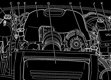
A. Climate Control Vents. See ClimateControlSystem
B.
on page3-20. Instrument Panel Cluster. See InstrumentPanel Cluster on page3-24.
C. Turn Signal/Multifunction Lever. See Turn
Signal/Multifunction Lever on page3-6.
D. Exterior and Interior Lamps Control. See Exterior
Lamps on page3-12 and Interior Lamps on page3-16.
E. Driver Information Center (DIC) buttons. See Driver
Information Center (DIC) on page3-42.
F. Audio Steering Wheel Controls. See AudioSteering
Wheel Controls on page3-82.
G. Storage Tray. See InstrumentPanelStorageArea
on page2-35.
H. Audio System. See AudioSystem(s)onpage3-58. I. Climate Control System. See ClimateControl
System on page3-20.
J. Transmission Shift Lever. See Automatic
TransmissionOperationonpage2-19 or Manual Transmission Operation on page2-21.
K. Cupholder. See Cupholder(s) on page2-35. L. Glovebox. See Glove Box on page2-35.
Hazard Warning Flashers Your hazard warning flashers let you warn others. They also let police know you have a problem. Your front and rear turn signal lamps will flash on and off.
The hazard warning flasher button is located on top of the steering column.
Your hazard warning flashers work no matter what position your key is in, and even if the key is not in the ignition. Press the button to make the front and rear turn signal lamps flash on and off. Press the button again to turn the flashers off. When the hazard warning flashers are on, your turn signals will not work. Other Warning Devices If you carry reflective triangles, you can set them up at the side of the road about 300 feet (100 m) behind your vehicle.
3-5
Horn To sound the horn, press the horn symbol on the steering wheel pad.
Tilt Wheel A tilt wheel allows you to adjust the steering wheel before you drive. You can raise it to the highest level to allow more room for the driver to enter and exit the vehicle.
The tilt lever is located on the driver’s side of the steering column, under the turn signal lever.
To tilt, hold the steering wheel and pull the tilt lever toward you. Move the wheel to a comfortable level, then release the tilt lever to lock the wheel in place.
3-6
Turn Signal/Multifunction Lever
The lever on the left side of the steering column includes the following: • G Turn and Lane Change Signals. Turnand
Lane-Change Signals on page3-7.
• 3 Headlamp High/Low-Beam Changer. Headlamp
High/Low-Beam Changer on page3-8.
• Flash-to-Pass Feature. See Flash-to-Passon
page3-8.
• N Windshield Wipers. See WindshieldWiperson
page3-8.
• L Windshield Washer. See WindshieldWasher
on page3-9.
• I Cruise Control. CruiseControlonpage3-9. For information on the exterior lamps, see Exterior Lamps on page3-12 later in this section.
Turn and Lane-Change Signals The turn signal has two upward (for right) and two downward (for left) positions. These positions allow you to signal a turn or a lane change. To signal a turn, move the lever all the way up or down. When the turn is finished, the lever will return automatically.
An arrow on the instrument panel cluster will flash in the direction of the turn or lane change.
To signal a lane change, just raise or lower the lever until the arrow starts to flash. Hold it there until you complete your lane change. The lever will return by itself when you release it. As you signal a turn or a lane change, if the arrows flash more quickly than normal, a signal bulb may be burned out and other drivers won’t see your turn signal. If a bulb is burned out, replace it to help avoid an accident. If the arrows do not go on at all when you signal a turn, check the fuse and for burned out bulbs. See Fuses and Circuit Breakers on page5-84. Turn Signal On Chime If your turn signal is left on for more than 3/4 of a mile (1.2 km), a chime will sound at each flash of the turn signal and a message will display on the DIC. See DICWarningsandMessagesonpage3-45
for additional information. To turn off the chime, move the turn signal lever to the off position.3-7
Headlamp High/Low-Beam Changer To change the headlamps from low to high beam, push the lever toward the instrument panel. To return to low-beam headlamps, pull the multifunction lever toward you. Then release it.
When the high beams are on, this indicator light on the instrument panel cluster will also be on.
Flash-to-Pass This feature lets you use your high-beam headlamps to signal a driver in front of you that you want to pass. It works even if your headlamps are in the automatic position. To use it, pull the turn signal lever toward you, then release it. If your headlamps are in the automatic position or on low beam, your high-beam headlamps will turn on. They’ll stay on as long as you hold the lever toward you.
3-8
The high-beam indicator on the instrument panel cluster will come on. Release the lever to return to normal operation.
Windshield Wipers N (Windshield Wipers): To use the windshield wipers, turn the band with the wiper symbol on it. 8(Mist): For a single wiping cycle, turn the band to mist. Hold it there until the wipers start. Then let go. The wipers will stop after one wipe. If you want more wipes, hold the band on mist longer. Delayed Wipers: You can set the wiper speed for a long or short delay between wipes. This can be very useful in light rain or snow. Turn the band to one of the dashed marks on the lever to choose the delay time. The closer to the top of the lever, the shorter the delay. 6 (Low Speed): For steady wiping at low speed, turn the band away from you to the first solid band past the delay settings. 1 (High Speed): For high-speed wiping, turn the band further, to the second solid band past the delay settings. 9(Off): Turn the band to this symbol to turn off your windshield wipers.
Windshield Washer
{CAUTION:
In freezing weather, do not use your washer until the windshield is warmed. Otherwise the washer fluid can form ice on the windshield, blocking your vision.
LQ (Windshield Washer): To spray washer fluid on the windshield, press the paddle. The wipers will clear the window and then either stop or return to your preset speed.
Cruise Control With cruise control, you can maintain a speed of about 25 mph (40 km/h) or more without keeping your foot on the accelerator. This can really help on long trips. Cruise control does not work at speeds below about 25 mph (40 km/h). If you apply your brakes, the cruise control will shut off.
{CAUTION:
Cruise control can be dangerous where you cannot drive safely at a steady speed. So, do not use your cruise control on winding roads or in heavy traffic. Cruise control can be dangerous on slippery roads. On such roads, fast changes in tire traction can cause needless wheel spinning, and you could lose control. Do not use cruise control on slippery roads.
{CAUTION:
If you leave your cruise control on when you are not using cruise, you might hit a button and go into cruise when you do not want to. You could be startled and even lose control. Keep the cruise control switch off until you want to use cruise control.
3-9
9 (Off): This position turns the cruise control system off and cancels memory of a set speed.
1. Move the cruise control switch to on. 2. Get up to the speed you want. 3. Press in the set button at the end of the lever and
release it.
4. Take your foot off the accelerator pedal. The
accelerator pedal will not go down.
The cruise light on the instrument panel cluster will illuminate when the cruise control is engaged.
Setting Cruise Control
Your cruise control is located at the end of your turn signal/multifunction lever.
R (On): Move the switch to this position to turn the cruise control system on. S (Resume/Accelerate): Move the switch to this position to resume a set speed or to accelerate. T (Set): Press this button, located at the end of the lever, to set a speed.
3-10
Resuming a Set Speed Suppose you set your cruise control at a desired speed and then apply your brakes or the clutch, if equipped. This, of course, shuts off the cruise control. But you do not need to reset it. Once you are going about 25 mph (40 km/h) or more, you can move the cruise control switch briefly from on to resume/accelerate. You will go right back up to your chosen speed and stay there. If you hold the switch at resume/accelerate, the vehicle will keep going faster until you release the switch or apply the brake. So unless you want to go faster, do not hold the switch at resume/accelerate. Increasing Speed While Using Cruise Control There are two ways to go to a higher speed: • Use the accelerator pedal to get to the higher
speed. Press the button at the end of the lever, then release the button and the accelerator pedal. You will now cruise at the higher speed.
• Move the cruise switch from on to resume/
accelerate. Hold it there until you get up to the speed you want, and then release the switch. To increase your speed in very small amounts, move the switch briefly to resume/accelerate. Each time you do this, your vehicle will go about 1 mph (1.6 km/h) faster.
Reducing Speed While Using Cruise Control There are two ways to reduce your speed: • Press and hold the button at the end of the lever
until you reach the lower speed you want, then release it.
• To slow down in very small amounts, briefly press and release the set button. Each time you do this, you will go about 1 mph (1.6 km/h) slower.
Passing Another Vehicle While Using Cruise Control Use the accelerator pedal to increase your speed. When you take your foot off the pedal, your vehicle will slow down to the cruise control speed you set earlier.
3-11
Using Cruise Control on Hills How well your cruise control will work on hills depends upon your speed, load and the steepness of the hills. When going up steep hills, you may want to step on the accelerator pedal to maintain your speed. When going downhill, you may have to brake or shift to a lower gear to keep your speed down. Of course, applying your brakes or the clutch, if equipped, takes you out of cruise control. Many drivers find this to be too much trouble and do not use cruise control on steep hills. Ending Cruise Control There are three ways to turn off the cruise control: • Step lightly on the brake pedal or clutch,
if equipped.
• Move the cruise switch to off, or • Shift the transmission to NEUTRAL (N). Erasing Speed Memory When you turn off the cruise control or the ignition, your cruise control set speed memory is erased.
3-12
Exterior Lamps
O(Exterior and Interior Lamps Controls): These controls (B) are located to the left of the steering wheel and are used to operate the exterior and interior lamps. D (Interior Lamps Control): The interior lamp control (A) is used to adjust the brightness of the instrument panel lights. For more information on interior lamps, see Interior Lamps on page3-16.
The exterior lamps control operates the following systems: • Headlamps • Taillamps • Parking Lamps • License Lamps • Sidemarker Lamps • Instrument Panel Lights • Interior Courtesy Lamps O (Fog Lamp Indicator Light): This light illuminates when the fog lamps are turned on. See FogLamps on page3-15 for more information.
AUTO (Automatic Headlamp System): Turning the exterior lamps control to this position activates the automatic headlamp system. See AutomaticHeadlamp System on page3-14 for more information.
; (Parking Lamps): Turning the exterior lamps control to this position turns on the parking lamps, license plate lamps, the sidemarker lamps and the instrument panel lights. 2(Headlamps): Turning the exterior lamps control to this position turns on the headlamps, together with the previously listed lamps and lights.
Headlamps on Reminder A reminder tone will sound when your headlamps or parking lamps are manually turned on, the driver’s door is open and your ignition is in OFF or ACCESSORY. To turn the tone off, turn the knob all the way counterclockwise. In the automatic mode, the headlamps turn off once the ignition key is in OFF.
3-13
Daytime Running Lamps (DRL) Daytime Running Lamps (DRL) can make it easier for others to see the front of your vehicle during the day. DRL can be helpful in many different driving conditions, but they can be especially helpful in the short periods after dawn and before sunset. Fully functional daytime running lamps are required on all vehicles first sold in Canada. The DRL system will make your headlamps come on at reduced brightness when the following conditions are met: • The ignition is on, • the exterior lamps knob is in AUTO, • the light sensor detects daytime light, and • the automatic transmission is not in PARK (P)
or the parking brake is not set on a manual transmission.
When the DRL are on, only your headlamps will be on. The taillamps, sidemarker and other lamps won’t be on. The instrument panel won’t be lit up either.
When it begins to get dark, the headlamps will automatically switch from DRL to the regular headlamps. To idle your vehicle with the DRL off, put your automatic transmission in PARK (P). The DRL will stay off until you shift out of PARK (P). If you have a manual transmission, set the parking brake when the ignition is off and then start your vehicle. The DRL will stay off until you release the parking brake.
Automatic Headlamp System When it is dark enough outside, your automatic headlamp system will turn on your headlamps at the normal brightness along with other lamps such as the taillamps, sidemarker, parking lamps and the instrument panel lights when the exterior lamps knob is turned to AUTO. See ExteriorLampsonpage3-12
for more information. The radio lights will also be on. Your vehicle is equipped with a light sensor on the top of the instrument panel. Be sure it is not covered or the system will be on whenever the ignition is on. The system may also turn on your lights when driving through a parking garage, heavy overcast weather or a tunnel. This is normal.3-14
There is a delay in the transition between the daytime and nighttime operation of the Daytime Running Lamps (DRL) and the automatic headlamp systems so that driving under bridges or bright overhead street lights does not affect the system. The DRL and automatic headlamp system will only be affected when the light sensor sees a change in lighting lasting longer than the delay. See DaytimeRunningLamps (DRL) on page3-14 for more information. To idle your vehicle with the automatic headlamp system off, set the parking brake while the ignition is off. Then start your vehicle. The automatic headlamp system will stay off until you release the parking brake, or until you shift out of PARK (P). You may be able to turn off your automatic headlamp system. See DaytimeRunningLamps(DRL)on page3-14 for more information. If you start your vehicle in a dark garage, the automatic headlamp system will come on immediately. Once you leave the garage, it will take approximately one minute for the automatic headlamp system to change to DRL if it is light outside. During that delay, your instrument panel cluster may not be as bright as usual.
Make sure your instrument panel brightness control is in the full bright position. See InstrumentPanelBrightness onpage3-16for more information. As with any vehicle, you should turn on the regular headlamp system when you need it.
Fog Lamps Use your fog lamps for better vision in foggy or misty conditions. Your ignition must be in RUN for your fog lamps to work. -(Fog Lamps): Press this button located on the exterior lamps control to turn the fog lamps on or off. The fog lamps will go off whenever you turn on the high-beam headlamps. When the high beams are turned off, the fog lamps will come on again. O (Fog Lamp Indicator Light): This light located on the exterior lamps control illuminates when the fog lamps are turned on.
3-15
D (Interior Lamp Control): The interior lamp control (A) is located to the left of the steering wheel and is used to adjust the brightness of the instrument panel lights.
Instrument Panel Brightness To adjust the brightness of the instrument panel lights, press lightly on the interior lamp control and release. The control will extend outward. Turn the control counterclockwise to brighten and clockwise to dim the instrument panel lights. Press on the control to return it to the stored position. Parade Dimming This feature prohibits the dimming of your instrument panel displays during daylight while your headlamps are on. When the light sensor reads darkness outside, you will be able to dim your instrument panel displays once again.
Interior Lamps
O(Exterior and Interior Lamp Controls): These controls (B) are used to operate the exterior and interior lamps. Information on the interior lamps follows. For more information on the exterior lamps, see Exterior Lamps on page3-12.
3-16
Theater Dimming This feature allows for a three to five-second fade out of the courtesy lamps instead of immediate turn off.
Exit Lighting With the exit lighting, the interior lamps will come on when you remove the key from the ignition to help you see while exiting the vehicle.
Perimeter Lighting When the button with the unlock symbol on the remote keyless entry transmitter is pressed, the DRL, parking lamps and back-up lamps will come on if it is dark enough outside. This feature can be personalized for up to two drivers. See DICVehiclePersonalizationonpage3-52 for more information.
Map Lamps If your vehicle has front map lamps, they are located on the inside rearview mirror. They will automatically come on for approximately 40 seconds when the doors are unlocked with the remote keyless entry transmitter or until the ignition key is turned to RUN or ACCESSORY. The lamps will also stay on for approximately 40 seconds after you exit the vehicle unless you lock the doors with the remote keyless entry transmitter. You can also turn the lamps on and off by pressing the button near each lamp.
Battery Run-Down Protection This feature shuts off all lamps that are left on for more than 10 minutes when the ignition is off. This will keep your battery from running down.
3-17
Center Console Switchbank The following controls are located on your center console switchbank:
Automatic Transmission shown,
Manual Transmission similar
A. Driver Power Window. See PowerWindowson
page2-12.
B. Traction Control System (TCS) (Automatic
Transmission Only). See TractionControlSystem (TCS)(AutomaticTransmission)onpage4-8.
3-18
C. Convertible Top. See ConvertibleToponpage2-51. D. Power Door Locks. See PowerDoorLockson
page2-10.
E. Passenger Power Window. See PowerWindowson
page2-12.
Accessory Power Outlets With accessory power outlets you can plug in auxiliary electrical equipment such as a cellular telephone or CB radio. There is an accessory power outlet located on either side of the ashtray on the instrument panel, and there is an outlet in the rear cargo area. A small cap must be removed to access an accessory power outlet. When not using an outlet be sure to cover it with the protective cap. Notice: Leaving electrical equipment on for extended periods will drain the battery. Always turn off electrical equipment when not in use and do not plug in equipment that exceeds the maximum amperage rating.
Certain electrical accessories may not be compatible with the accessory power outlet and could result in blown vehicle or adapter fuses. If you experience a problem, see your dealer for additional information on accessory power outlets. Notice: Adding any electrical equipment to your vehicle may damage it or keep other components from working as they should. The repairs would not be covered by your warranty. Check with your dealer before adding electrical equipment. When adding electrical equipment, be sure to follow the proper installation instructions included with the equipment. Notice: Improper use of the power outlet can cause damage not covered by your warranty. Do not hang any type of accessory or accessory bracket from the plug because the power outlets are designed for accessory power plugs only.
Ashtrays and Cigarette Lighter Your vehicle has an ashtray and cigarette lighter. To access, push the upper edge of the center instrument panel door until it clicks and then release. The door will open to expose the ashtray and cigarette lighter. Press the lighter all the way in and release it. It will pop back out by itself once the element has heated for use. Notice: If you put papers or other flammable items in the ashtray, hot cigarettes or other smoking materials could ignite them and possibly damage your vehicle. Never put flammable items in the ashtray. Notice: Holding a cigarette lighter in while it is heating will not allow the lighter to back away from the heating element when it is hot. Damage from overheating may occur to the lighter or heating element, or a fuse could be blown. Do not hold a cigarette lighter in while it is heating. Do not use anything other than the cigarette lighter in the heating element.
3-19
Climate Controls
Climate Control System
A. Temperature Knob B. Fan Knob C. Mode Knob With this system you can control the heating, cooling, and ventilation for your vehicle. Temperature Knob The left knob on the control panel is used to adjust the temperature of the air in the vehicle. Turn the knob clockwise or counterclockwise to increase or decrease the temperature.
3-20
#(Air Conditioning): Press this button located on the temperature knob to turn the air-conditioning system on or off. An indicator light on the button will come on to let you know the air conditioning is activated. When the system is on, this setting cools and dehumidifies the air entering your vehicle and directs it through the floor ducts as well as the instrument panel outlets. The air conditioning system removes moisture from the air, so you may sometimes notice a small amount of water dripping underneath your vehicle while idling or after turning off the engine. This is normal. The air conditioning will not function if the fan is turned off. Fan Knob The center knob on the control panel is used to control the fan speed. Turn the knob clockwise or counterclockwise to increase or decrease the fan speed. ? (Recirculation): This mode keeps outside air from coming in the vehicle. It can be used to prevent outside air and odors from entering your vehicle or help heat or cool the air inside your vehicle more quickly.
Press this button on the fan knob to turn the recirculation mode on or off. An indicator light on the button will come on to let you know the recirculation mode is activated.
Recirculation is only available in the bi-level and vent modes. If you push the recirculation button while the system is in any other mode, the light on the button will flash to indicate that recirculation is not available. Mode Knob The right knob on the control panel is used to direct the airflow inside your vehicle. Turn the knob to select one of the following modes: H (Vent): Select this mode to direct air to the instrument panel outlets. ) (Bi-Level): Select this mode to direct approximately half of the air to the instrument panel outlets, and the remaining air to the floor outlets and the defroster and side window outlets. Cooler air is directed to the upper outlets and warmer air to the floor outlets. 6 (Floor): Select this mode to direct air to the floor outlets. Recirculation does not work in this mode.
Defogging and Defrosting Fog on the inside of windows is a result of high humidity (moisture) condensing on the cool window glass. This can be minimized if the climate control system is used properly. There are two modes to clear fog or frost from your windshield and side windows. Use the defog mode to clear the windows of fog or moisture and warm the passengers. Use the defrost mode to remove fog or frost from the windshield more quickly. For best results, clear all snow and ice from the windshield before defrosting. / (Floor/Defog): This mode directs half of the air to the windshield and the side window outlets and the other half to the floor outlets. When you select this mode, the system runs the air-conditioning compressor unless the outside temperature is at or below freezing. Recirculation is not available in this mode. 0 (Defrost): This mode directs most of the air to the windshield, with some air directed to the side window outlets and the floor outlets. When you select this mode, the system runs the air-conditioning compressor unless the outside temperature is at or below freezing. Recirculation is not available in this mode.
3-21
1 (Maximum Defrost): This mode directs most of the air to the windshield, with some air directed to the side window outlets and the floor outlets. The rear window defogger and heated outside mirrors will turn on, and the fan speed will be at the highest setting (5). The temperature will be at the hottest setting also. Recirculation is not available in this mode.
If this mode was selected when you turn your vehicle off, the warmest temperature and highest fan speed will be restored when the vehicle is started, regardless of the temperature and fan setting. Do not drive the vehicle until all the windows are clear. Rear Window Defogger The rear window defogger uses a warming grid to remove fog from the rear window. The rear window defogger will only work when the ignition is on. = (Rear): Press this button on the right knob to turn the rear window defogger on or off. An indicator light on the button will come on to let you know that the rear window defogger is activated.
When the rear defogger button is pressed, the outside heated mirrors will warm to help clear any fog or frost from the surface of the mirrors. Notice: Using a razor blade or sharp object to clear the inside rear window may damage the rear window defogger. Repairs would not be covered by your warranty. Do not clear the inside of the rear window with sharp objects.
Outlet Adjustment Use the levers located in the center of each outlet to change the direction of the airflow. Operation Tips • Clear away any ice, snow or leaves from the air
inlets at the base of the windshield that may block the flow of air into your vehicle.
• Use of non-GM approved hood deflectors may adversely affect the performance of the system.
• Keep the path under the front seats clear of objects to help circulate the air inside of your vehicle more effectively.
3-22
Warning Lights, Gages, and Indicators This part describes the warning lights and gages that may be on your vehicle. The pictures will help you locate them. Warning lights and gages can signal that something is wrong before it becomes serious enough to cause an expensive repair or replacement. Paying attention to your warning lights and gages could also save you or others from injury. Warning lights come on when there may be or is a problem with one of your vehicle’s functions. As you will see in the details on the next few pages, some warning lights come on briefly when you start the engine just to let you know they’re working. If you are familiar with this section, you should not be alarmed when this happens.
Gages can indicate when there may be or is a problem with one of your vehicle’s functions. Often gages and warning lights work together to let you know when there’s a problem with your vehicle. When one of the warning lights comes on and stays on when you are driving, or when one of the gages shows there may be a problem, check the section that tells you what to do about it. Please follow this manual’s advice. Waiting to do repairs can be costly, and even dangerous. So please get to know your warning lights and gages. They’re a big help. Your vehicle also has a Driver Information Center (DIC) that works along with the warning lights and gages. See DriverInformationCenter(DIC)onpage3-42 for more information.
3-23
Instrument Panel Cluster Your instrument panel cluster is designed to let you know at a glance how your vehicle is running. You’ll know how fast you’re going, about how much fuel you’ve used, and many other things you’ll need to know to drive safely and economically.
United States Automatic Transmission shown, Canada and Manual Transmission similar
3-24
Trip Odometer The trip odometer can tell you how far your vehicle has been driven since you last set the trip odometer to zero. Your trip odometer is part of your Driver Information Center (DIC). The trip information button toggles to display your trip odometer, Trip A, and Trip B functions. See “Trip Odometer” under DICControls andDisplaysonpage3-42 for more information.
Speedometer and Odometer The speedometer lets you see your speed in both miles per hour (mph) and kilometers per hour (km/h). The odometer shows how far your vehicle has been driven, in either miles (used in the United States) or kilometers (used in Canada). The odometer mileage can be checked without the vehicle running. Turn the ignition to RUN and press the trip information button located on the steering wheel. See DICControlsandDisplaysonpage3-42 for more information. You may wonder what happens if your vehicle needs a new odometer installed. If the new one can be set to the mileage total of the old odometer, then it must be. But if it can’t, then it’s set at zero, and a label must be put on the driver’s door to show the old mileage reading when the new odometer was installed.
3-25
Tachometer Notice: If you operate the engine with the tachometer in the shaded warning area, your vehicle could be damaged, and the damages would not be covered by your warranty. Do not operate the engine with the tachometer in the shaded warning area. The tachometer displays the engine speed in revolutions per minute (rpm).
Engine Speed Limiter Fuel will shut off at about 6500 rpm. It will turn back on again once the vehicle rpm drops below 6500.
Safety Belt Reminder Light When the key is turned to run or start, a chime will be provided for several seconds to remind people to buckle their safety belts. The driver safety belt light will also be provided and stay on for several seconds, then it will flash for several more. You should buckle your seat belt.
This chime and light will be repeated if the driver remains unbuckled and the vehicle is in motion.
If the driver’s belt is buckled, neither the chime nor the light will be provided.
3-26
Airbag Readiness Light There is an airbag readiness light on the instrument panel cluster, which shows the airbag symbol. The system checks the airbag’s electrical system for malfunctions. The light tells you if there is an electrical problem. The system check includes the airbag sensors, the airbag modules, the wiring and the crash sensing and diagnostic module. For more information on the airbag system, see AirbagSystemonpage1-38.
This light will come on when you start your vehicle, and it will flash for a few seconds. Then the light should go out. This means the system is ready.
If the airbag readiness light stays on after you start the vehicle or comes on when you are driving, your airbag system may not work properly. Have your vehicle serviced right away.
{CAUTION:
If the airbag readiness light stays on after you start your vehicle, it means the airbag system may not be working properly. The airbags in your vehicle may not inflate in a crash, or they could even inflate without a crash. To help avoid injury to yourself or others, have your vehicle serviced right away if the airbag readiness light stays on after you start your vehicle.
The airbag readiness light should flash for a few seconds when you turn the ignition key to RUN. If the light doesn’t come on then, have it fixed so it will be ready to warn you if there is a problem.
3-27
Airbag Off Light When you turn the passenger’s frontal airbag off, the airbag off light, located on the roof panel above the rearview mirror, will come on and stay on to remind you that the airbag has been turned off. This light will go off when you turn the passenger’s frontal airbag back on again. See AirbagOffSwitchonpage1-47 for more on this, including important safety information.
United States
3-28
Canada
{CAUTION:
If the passenger’s frontal airbag is turned off for a person who is not in a risk group identified by the national government, that person will not have the extra protection of a frontal airbag. In a crash, the airbag would not be able to inflate and help protect the person sitting there. Do not turn off the passenger’s frontal airbag unless the person sitting there is in a risk group. See AirbagOffSwitchon page1-47 for more on this, including important safety information.
{CAUTION:
If the airbag readiness light ever comes on when you have turned off the passenger’s frontal airbag, it means that something may be wrong with the airbag system. The passenger’s frontal airbag could inflate even though the switch is off. If this ever happens, do not let anyone whom the national government has identified as a member of a passenger airbag risk group sit in the passenger’s position (for example, do not secure a rear-facing child restraint in your vehicle) until you have your vehicle serviced. See AirbagOffSwitch onpage1-47.
Charging System Light
The charging system light will come on briefly when you turn on the ignition, but the engine is not running, as a check to show you it is working.
It should go out once the engine is running. If it stays