- 2001 Chevrolet Silverado Owners Manuals
- Chevrolet Silverado Owners Manuals
- 2013 Chevrolet Silverado Owners Manuals
- Chevrolet Silverado Owners Manuals
- 2015 Chevrolet Silverado Owners Manuals
- Chevrolet Silverado Owners Manuals
- 2016 Chevrolet Silverado Owners Manuals
- Chevrolet Silverado Owners Manuals
- 2010 Chevrolet Silverado Owners Manuals
- Chevrolet Silverado Owners Manuals
- 2012 Chevrolet Silverado Owners Manuals
- Chevrolet Silverado Owners Manuals
- 2004 Chevrolet Silverado Owners Manuals
- Chevrolet Silverado Owners Manuals
- 2008 Chevrolet Silverado Owners Manuals
- Chevrolet Silverado Owners Manuals
- 2014 Chevrolet Silverado Owners Manuals
- Chevrolet Silverado Owners Manuals
- 2000 Chevrolet Silverado Owners Manuals
- Chevrolet Silverado Owners Manuals
- 2011 Chevrolet Silverado Owners Manuals
- Chevrolet Silverado Owners Manuals
- 2003 Chevrolet Silverado Owners Manuals
- Chevrolet Silverado Owners Manuals
- 2007 Chevrolet Silverado Owners Manuals
- Chevrolet Silverado Owners Manuals
- 2005 Chevrolet Silverado Owners Manuals
- Chevrolet Silverado Owners Manuals
- Download PDF Manual
-
larger percentage of the weight (kingpin weight) on the tow vehicle than conventional trailers. Make sure this weight does not cause the vehicle to exceed GAWR or GVWR. Fifth-wheel or gooseneck kingpin weight should be 15 to 25 percent of the trailer weight up to the maximum amount specified in the trailering chart for the vehicle. See “Weight of the Trailer” under Trailer Towing on page 9‑90 for more information.
The hitch should be located in the pickup bed so that its centerline is over or slightly in front of the rear axle. Take care that it is not so far forward that it will contact the back of the cab in sharp turns. This is especially important for short box pickups. Trailer pin box extensions and sliding fifth-wheel hitch assemblies can help this condition. There should be at least six inches of clearance between the top of the pickup box and the bottom of the trailer shelf that extends over the box. Make sure the hitch is attached to the tow vehicle frame rails. Do not use the pickup box for support.
Weight-Distributing Hitch Adjustment
A. Body to Ground Distance B. Front of Vehicle When using a weight-distributing hitch, the spring bars should be adjusted so the distance (A) is the same after coupling the trailer to the tow vehicle and adjusting the hitch.
Chevrolet Silverado Owner Manual - 2012
Black plate (108,1)
9-108
Driving and Operating
Safety Chains Always attach chains between the vehicle and the trailer. Cross the safety chains under the tongue of the trailer to help prevent the tongue from contacting the road if it becomes separated from the hitch. Instructions about safety chains may be provided by the hitch manufacturer or by the trailer manufacturer. If the trailer being towed weighs up to 2 271 kg (5,000 lbs) with a factory-installed step bumper, safety chains may be attached to the attaching points on the bumper; otherwise, safety chains should be attached to holes on the trailer hitch platform. Always leave just enough slack so the combination can turn. Never allow safety chains to drag on the ground.
Trailer Brakes A loaded trailer that weighs more than 900 kg (2,000 lbs) needs to have its own brake system that is adequate for the weight of the trailer. Be sure to read and follow the instructions for the trailer brakes so they are installed, adjusted, and maintained properly. Do not tap into the vehicle's hydraulic brake system. Auxiliary Battery The auxiliary battery provision can be used to supply electrical power to additional equipment that may be added, such as a slide-in camper. If the vehicle has this provision, this relay will be located on the driver side of the vehicle, next to the underhood electrical center.
Be sure to follow the proper installation instructions included with any electrical equipment that is installed. Notice: Leaving electrical equipment on for extended periods will drain the battery. Always turn off electrical equipment when not in use and do not use equipment that exceeds the maximum amperage rating of 40 amperes for the auxiliary battery provision. Trailer Wiring Harness The vehicle is equipped with one of the following wiring harnesses for towing a trailer or hauling a slide-in camper.
Chevrolet Silverado Owner Manual - 2012
Black plate (109,1)
Driving and Operating
9-109
Basic Trailer Wiring All regular, extended cab and crew cab pickups have a seven-wire trailer towing harness. For vehicles not equipped with heavy duty trailering, the harness is secured to the vehicle's frame behind the spare tire mount. The harness requires the installation of a trailer connector, which is available through your dealer. If towing a light-duty trailer with a standard four-way round pin connector, an adapter is available from your dealer.
Heavy-DutyTrailer Wiring Harness Package
For vehicles equipped with heavy duty trailering, the harness connector is mounted in the bumper. The seven-wire harness contains the following trailer circuits: . Yellow: Left Stop/Turn Signal . Dark Green: Right Stop/Turn
Signal
. Brown: Taillamps
. White: Ground
Light Green: Back-up Lamps
. Red: Battery Feed* . Dark Blue: Trailer Brake* *The fuses for these two circuits are installed in the underhood electrical center, but the wires are not connected. They should be connected by your dealer or a qualified service center. The fuse and wire for the ITBC is factory installed and connected if the vehicle is equipped with an ITBC. The fuse for the battery feed is not required if the vehicle has an auxiliary battery. If the vehicle does not have an auxiliary battery, have your dealer or authorized service center install the required fuse.
Chevrolet Silverado Owner Manual - 2012
Black plate (110,1)
9-110
Driving and Operating
The harness contains the following camper/trailer circuits: . Yellow: Left Stop/Turn Signal . Dark Green: Right Stop/Turn
Signal
. Brown: Taillamps . White: Ground
Light Green: Back-up Lamps
. Red: Battery Feed . Dark Blue: Trailer Brake
If charging a remote (non-vehicle) battery, press the Tow/Haul Mode button, if equipped, located at the end of the shift lever. This will boost the vehicle system voltage and properly charge the battery. If the trailer is too light for Tow/Haul Mode, or the vehicle is not equipped with Tow/Haul, turn on the headlamps as a second way to boost the vehicle system and charge the battery.
Camper/Fifth-Wheel Trailer Wiring Package The seven-wire camper harness is located under the front edge of the pickup box on the driver side of the vehicle, attached to the frame bracket. A connector must be added to the wiring harness which connects to the camper.
If the vehicle is equipped with the “Heavy-Duty Trailering” option, please refer to “Heavy-Duty Trailer Wiring Package” earlier in this section. When the camper-wiring harness is ordered without the heavy-duty trailering package, a seven-wire harness with a seven-pin connector is located at the rear of the vehicle and is tied to the vehicle's frame.
Chevrolet Silverado Owner Manual - 2012
Black plate (111,1)
Driving and Operating
9-111
ITBC must be disconnected. Do not power both ITBC and aftermarket controllers to control the trailer brakes at the same time. Tow/Haul Mode
This indicator light on the instrument panel cluster comes on when the Tow/Haul Mode is on. Tow/Haul is a feature that assists when pulling a heavy trailer or a large or heavy load. See Tow/Haul Mode on page 9‑44 for more information.
Pressing this button at the end of the shift lever turns on and off the Tow/Haul Mode.
Electric Brake Control Wiring Provisions These wiring provisions are included with the vehicle as part of the trailer wiring package. These provisions are for an electric brake controller. The instrument panel contains blunt cut wires behind the steering column for the trailer brake controller. The harness contains the following wires: . Dark Blue: Brake Signal to
Trailer Connector
. Red/Black: Battery
Light Blue/White: Brake Switch
. White: Ground The harness should be installed by your dealer or a qualified service center. If the vehicle is equipped with an Integrated Trailer Brake Control (ITBC) System, the blunt cuts exist, but are not connected further in the harness. If an aftermarket trailer brake controller is installed, the
Chevrolet Silverado Owner Manual - 2012
Black plate (112,1)
9-112
Driving and Operating
Tow/Haul is designed to be most effective when the vehicle and trailer combined weight is at least 75 percent of the vehicle's Gross Combined Weight Rating (GCWR). See “Weight of the Trailer” under Trailer Towing on page 9‑90. Tow/Haul is most useful under the following driving conditions: . When pulling a heavy trailer or a
large or heavy load through rolling terrain.
. When pulling a heavy trailer or a
large or heavy load in stop-and-go traffic.
. When pulling a heavy trailer or a
large or heavy load in busy parking lots where improved low speed control of the vehicle is desired.
Operating the vehicle in Tow/Haul when lightly loaded or with no trailer at all will not cause damage. However, there is no benefit to the selection of Tow/Haul when the vehicle is unloaded. Such a selection when unloaded may result in unpleasant engine and transmission driving characteristics and reduced fuel economy. Tow/Haul is recommended only when pulling a heavy trailer or a large or heavy load. Integrated Trailer Brake Control System
The vehicle may have an Integrated Trailer Brake Control (ITBC) system for electric trailer brakes.
This symbol is located on the Trailer Brake Control Panel on vehicles with an Integrated Trailer Brake Control system. The power output to the trailer brakes is based on the amount of brake pressure being applied by the vehicle’s brake system. This available power output to the trailer brakes can be adjusted to a wide range of trailering situations. The ITBC system is integrated with the vehicle’s brake, antilock brake, and StabiliTrak (if equipped) systems. In trailering conditions that cause the vehicle’s antilock brake or StabiliTrak systems to activate, power sent to the trailer's brakes will be automatically adjusted to minimize trailer wheel lock-up. This does not imply that the trailer has StabiliTrak. Non-hybrid vehicles with StabiliTrak have a Trailer Sway Control (TSC) feature. See Trailer Sway Control (TSC) on page 9‑118.
Chevrolet Silverado Owner Manual - 2012
Black plate (113,1)
Driving and Operating
9-113
Non-hybrid vehicles with StabiliTrak have a Hill Start Assist (HSA) feature. See Hill Start Assist (HSA) on page 9‑65. If the vehicle’s brake, antilock brake, or StabiliTrak systems are not functioning properly, the ITBC system may not be fully functional or may not function at all. Make sure all of these systems are fully operational to ensure full functionality of the ITBC system. The ITBC system is powered through the vehicle's electrical system. Turning the ignition off will also turn off the ITBC system. The ITBC system is fully functional only when the ignition is in ON or in RUN. The ITBC system can only be used with trailers with electric brakes.
{ WARNING
Connecting a trailer that is not compatible with the ITBC system may result in reduced or complete loss of trailer braking. There may be an increase in stopping distance or trailer instability which could result in personal injury or damage to the vehicle, trailer, or other property. An aftermarket controller may be available for use with trailers with surge, air, or electric‐over‐hydraulic trailer brake systems. To determine the type of brakes on the trailer and the availability of controllers, check with your trailer manufacturer or dealer.
When trailering, make sure of the following:
The ITBC system is used only with trailers that are equipped with electric brakes.
. All applicable local and federal
laws and regulations are followed.
. All electrical and mechanical connections to the trailer are made correctly. The trailer’s brakes are in proper working condition. The trailer and vehicle are properly loaded for the towing condition.
The ITBC system is a factory-installed item. Out-of-factory installation of this system should not be attempted. GM is not responsible for warranty or performance of the system resulting from out-of-factory installation.
Chevrolet Silverado Owner Manual - 2012
Black plate (114,1)
9-114
Driving and Operating
Trailer Brake Control Panel
A. Manual Trailer Brake Apply
Lever
B. Trailer Gain Adjustment Buttons The ITBC system has a control panel located on the instrument panel to the left of the steering column. See Instrument Panel (Premium Version) on page 1‑6 or Instrument Panel (Base/Uplevel Version) on page 1‑2 for more information. The control panel allows adjustment to the amount of output, referred to as trailer gain,
available to the electric trailer brakes and allows manual application of the trailer brakes. The Trailer Brake Control Panel is used along with the Trailer Brake Display Page on the DIC to adjust and display power output to the trailer brakes.
Trailer Brake DIC Display Page The ITBC system displays messages on the vehicle’s Driver Information Center (DIC). See Driver Information Center (DIC) on page 5‑33 for more information. The display page indicates Trailer Gain setting, power output to the electric trailer brakes, trailer connection, and system operational status. The Trailer Brake Display Page can be displayed by performing any of the following actions: . Scrolling through the DIC menu
pages using the odometer trip stem or the DIC Vehicle Information button (if equipped).
. Pressing a Trailer Gain
button—If the Trailer Brake Display Page is not currently displayed, pressing a Trailer Gain button will first recall the current Trailer Gain setting. After the Trailer Brake Display Page is displayed, each press and release of the gain buttons will then cause the Trailer Gain setting to change.
. Activating the Manual Trailer
Brake Apply lever.
. Connecting a trailer equipped
with electric trailer brakes.
All DIC warning and service messages must first be acknowledged by the driver by pressing the odometer trip stem or the DIC Vehicle Information button (if equipped) before the Trailer Brake Display Page can be displayed and Trailer Gain can be adjusted.
Chevrolet Silverado Owner Manual - 2012
Black plate (115,1)
Driving and Operating
9-115
TRAILER GAIN: This setting is displayed any time the Trailer Brake Display Page is active. This setting can be adjusted from 0.0 to 10.0
with either a trailer connected or disconnected. To adjust the Trailer Gain, press one of the Trailer Gain adjustment buttons located on the Trailer Brake Control Panel. Press and hold a gain button to cause the Trailer Gain to continuously adjust. To turn the output to the trailer off, adjust the Trailer Gain setting to 0.0 (zero). 0.0 (zero) gain is the factory default setting. To properly adjust trailer gain, see “Trailer Gain Adjustment Procedure” later in this section. TRAILER OUTPUT: This is displayed any time a trailer with electric brakes is connected. Output to the electric brakes is based on the amount of vehicle braking present and relative to the Trailer Gain setting. Output is displayed from 0 to 10 bars for each gain setting.Non-hybrid vehicles with Trailer Sway Control (TSC) or Hill Start Assist (HSA), output to the electric trailer brakes may be displayed when the systems are active. See Trailer Sway Control (TSC) on page 9‑118 and Hill Start Assist (HSA) on page 9‑65. The Trailer Output will indicate “- - - - - -” on the Trailer Brake Display Page whenever the following occur: . No trailer is connected . A trailer without electric brakes is connected (no DIC message is displayed)
. A trailer with electric brakes has
become disconnected (a CHECK TRAILER WIRING message will also be displayed on the DIC) There is a fault present in the wiring to the electric trailer brakes (a CHECK TRAILER WIRING message will also be displayed on the DIC)
There is a fault in the ITBC system (a SERVICE TRAILER BRAKE SYSTEM message will also be displayed in the DIC)
Manual Trailer Brake Apply The Manual Trailer Brake Apply Lever is located on the Trailer Brake Control Panel and is used to apply the trailer’s electric brakes independent of the vehicle’s brakes. This lever is used in the Trailer Gain Adjustment Procedure to properly adjust the power output to the trailer brakes. Sliding the lever to the left will apply only the trailer brakes. The power output to the trailer is indicated in the Trailer Brake Display Page on the DIC. If the vehicle’s service brakes are applied while using the Manual Trailer Brake Apply Lever, the trailer output power will be the greater of the two. The trailer's and the vehicle's brake lamps will come on when either vehicle braking or manual trailer brakes are applied.
Chevrolet Silverado Owner Manual - 2012
Black plate (116,1)
9-116
Driving and Operating
Trailer Gain Adjustment Procedure Trailer Gain should be set for a specific trailering condition and must be adjusted any time vehicle loading, trailer loading, or road surface conditions change. Setting the Trailer Gain properly is needed for the best trailer stopping performance. A trailer that is over-gained may result in locked trailer brakes. A trailer that is under-gained may result in not enough trailer braking. Both of these conditions may result in poorer stopping and stability of the vehicle and trailer.
Use the following procedure to correctly adjust Trailer Gain for each towing condition: 1. Make sure the trailer brakes are
in proper working condition.
2. Connect a properly loaded trailer
to the vehicle and make all necessary mechanical and electrical connections. See Vehicle Load Limits on page 9‑17 for more information. 3. After the electrical connection is made to a trailer equipped with electric brakes:
A TRAILER CONNECTED message will be briefly displayed on the DIC. The Trailer Brake Display Page will appear on the DIC showing TRAILER GAIN and TRAILER OUTPUT.
In the Trailer Output display on the DIC, “- - - - - -” will disappear if there is no error present. Connecting a trailer without electric brakes will not clear the six dashed lines.
4. Adjust the Trailer Gain by using
the gain adjustment (+ / -) buttons on the Trailer Brake Control Panel.
5. Drive the vehicle with the trailer attached on a level road surface representative of the towing condition and free of traffic at about 32 to 40 km/h (20 to 25 mph) and fully apply the Manual Trailer Brake Apply Lever. Adjusting trailer gain at speeds lower than 32 to 40 km/h (20 to 25 mph) may result in an incorrect gain setting.
Chevrolet Silverado Owner Manual - 2012
Black plate (117,1)
Driving and Operating
9-117
6. Adjust the Trailer Gain to just
below the point of trailer wheel lock-up, indicated by trailer wheel squeal or tire smoke when a trailer wheel locks. Trailer wheel lock-up may not occur if towing a heavily loaded trailer. In this case, adjust the Trailer Gain to the highest allowable setting for the towing condition.
7. Re-adjust Trailer Gain any time
vehicle loading, trailer loading or road surface conditions change or if trailer wheel lock-up is noticed at any time while towing.
Other ITBC-Related DIC Messages In addition to displaying TRAILER GAIN and TRAILER OUTPUT through the DIC, trailer connection and ITBC system status are displayed on the DIC.
TRAILER CONNECTED: This message will be briefly displayed when a trailer with electric brakes is first connected to the vehicle. This message will automatically turn off in about 10 seconds. The driver can also acknowledge this message before it automatically turns off. CHECK TRAILER WIRING: This message will be displayed if: 1. The ITBC system first
determines connection to a trailer with electric brakes and then the trailer harness becomes disconnected from the vehicle. If the disconnect occurs while the vehicle is stationary, this message will automatically turn off in about 30 seconds. This message will also turn off if the driver acknowledges this message or if the trailer harness is re-connected.
If the disconnect occurs while the vehicle is moving, this message will continue until the ignition is turned off. This message will also turn off if the driver acknowledges this message or if the trailer harness is re-connected.
2. There is an electrical fault in the
wiring to the electric trailer brakes. This message will continue as long as there is an electrical fault in the trailer wiring. This message will also turn off if the driver acknowledges this message.
To determine if the electrical fault is on the vehicle side or trailer side of the trailer wiring harness connection, do the following: 1. Disconnect the trailer wiring
harness from the vehicle.
2. Turn the ignition off. 3. Wait 10 seconds, then turn the
ignition back to RUN.
Chevrolet Silverado Owner Manual - 2012
Black plate (118,1)
9-118
Driving and Operating
4.
If the CHECK TRAILER WIRING message re-appears, the electrical fault is on the vehicle side. If the CHECK TRAILER WIRING message only re-appears when connecting the trailer wiring harness to the vehicle, the electrical fault is on the trailer side.
SERVICE TRAILER BRAKE SYSTEM: This message will be displayed when there is a problem with the ITBC system. If this message persists over multiple ignition cycles, there is a problem with the ITBC system. Take the vehicle to an authorized GM dealer to have the ITBC system diagnosed and repaired.
If either the CHECK TRAILER WIRING or SERVICE TRAILER BRAKE SYSTEM message is displayed while driving the vehicle, power is no longer available to the trailer brakes. When traffic conditions allow, carefully pull the vehicle over to the side of the road and turn the ignition off. Check the wiring connection to the trailer and turn the ignition back on. If either of these messages continues, either the vehicle or trailer needs service. An authorized GM dealer may be able to diagnose and repair problems with the trailer. However, any diagnosis and repair of the trailer is not covered under the vehicle warranty. Please contact your trailer dealer for assistance with trailer repairs and trailer warranty information.
Trailer Sway Control (TSC) Non-hybrid vehicles with StabiliTrak have a Trailer Sway Control (TSC) feature. If the vehicle is towing a trailer and the system detects that the trailer is swaying, the vehicle brakes are applied without the driver pressing the brake pedal. If the vehicle is equipped with the Integrated Trailer Brake Control (ITBC) system, StabiliTrak may also apply the trailer brakes. The TCS/ StabiliTrak warning light will flash on the instrument panel cluster to notify the driver to reduce speed. If the trailer continues to sway, StabiliTrak will reduce engine torque to help slow the vehicle. See StabiliTrak® System on page 9‑65 for more information. Adding non‐dealer accessories can affect the vehicle performance. See Accessories and Modifications on page 10‑4 for more information.
Chevrolet Silverado Owner Manual - 2012
Black plate (119,1)
Driving and Operating
9-119
Adding a Snow Plow or Similar Equipment Before installing a snow plow on the vehicle, here are some things you need to know: Notice: If the vehicle does not have the snow plow prep package, adding a plow can damage the vehicle, and the repairs would not be covered by warranty. Unless the vehicle was built to carry a snow plow, do not add one to the vehicle. If the vehicle has the snow plow prep package, called RPO VYU, then the payload the vehicle can carry will be reduced when a snow plow is installed. The vehicle can be damaged if either the front or rear axle ratings or the Gross Vehicle Weight (GVW) are exceeded.
Some vehicles are built with a special snow plow prep package, called RPO VYU. If the vehicle has this option, you can add a plow to it, provided certain weights, such as the weights on the vehicle's axles and the Gross Vehicle Weight (GVW), are not exceeded. The plow the vehicle can carry depends on many things, such as:
The options the vehicle came with, and the weight of those options. The weight and number of passengers intended to be carried. The weight of items added to the vehicle, like a tool box or truck cap. The total weight of any additional cargo intended to be carried.
Conversions and Add-Ons
Add-On Electrical Equipment Notice: Do not add anything electrical to the vehicle unless you check with your dealer first. Some electrical equipment can damage the vehicle and the damage would not be covered by the vehicle's warranty. Some add-on electrical equipment can keep other components from working as they should. Add-on equipment can drain the vehicle's 12‐volt battery, even if the vehicle is not operating. The vehicle has an airbag system. Before attempting to add anything electrical to the vehicle, see Servicing the Airbag-Equipped Vehicle on page 3‑42 and Adding Equipment to the Airbag-Equipped Vehicle on page 3‑43.
Chevrolet Silverado Owner Manual - 2012
Black plate (120,1)
9-120
Driving and Operating
Say, for example, you have a 318 kg (700 lb) snow plow. The total weight of all occupants and cargo inside the cab should not exceed 135 kg (300 lb). This means that you may only be able to carry one passenger. But, even this may be too much if there is other equipment already adding to the weight of the vehicle. Here are some guidelines for safely carrying a snow plow on the vehicle: . Make sure the weight on the front and rear axles does not exceed the axle rating for each. For the front axle, if more cargo or passengers must be carried, appropriate counter ballast must be installed rear of the rear axle. Counter ballast must be properly secured so it will not move during driving.
Follow the snow plow manufacturer's recommendations regarding rear ballast. Rear ballast may be required to ensure a proper front and rear weight distribution ratio, even though the actual weight at the front axle may be less than the front axle rating. The snow plow manufacturer or installer can assist you in determining the amount of rear ballast required, to help make sure the snowplow/vehicle combination does not exceed the GVW rating, the front and rear axle ratings, and the front and rear weight distribution ratio. The total vehicle must not exceed the GVW rating.
Front axle reserve capacity is the difference between the Gross Axle Weight Rating (GAWR) and the front axle weight of the vehicle with full fuel and passengers. Basically, it is the amount of weight that can be added to the front axle before reaching the front GAWR. The front axle reserve capacity for the vehicle can be found in the lower right corner of the Certification/Tire label, as shown.
Chevrolet Silverado Owner Manual - 2012
Black plate (121,1)
Driving and Operating
9-121
In order to calculate the amount of weight any front accessory, such as a snow plow, is adding to the front axle, use the following formula:
(W x (A + W.B.)) /W.B.= Weight the accessory is adding to the front axle.
Where:
W = Weight of added accessory A = Distance that the accessory is in front of the front axle W.B. = Vehicle Wheelbase For example, adding a 318 kg (700 lb) snow plow actually adds more than 318 kg (700 lb) to the front axle. Using the formula, if the snow plow is 122 cm (4 ft) in front of the front axle and the wheel base is 305 cm (10 ft), then:
W = 318 kg (700 lb) A = 122 cm (4 ft) W.B. = 305 cm (10 ft)
(W x (A + W.B.))/W.B. = (318 x (122 + 305))/305 = 445 kg (980 lbs) So, if the front axle reserve capacity is more than 445 kg (980 lbs), the snow plow could be added without exceeding the front GAWR.
United States
Canada
Chevrolet Silverado Owner Manual - 2012
Black plate (122,1)
9-122
Driving and Operating
Heavier equipment can be added on the front of the vehicle if it is compensated for by carrying fewer passengers, less cargo, or by positioning cargo toward the rear. This has the effect of reducing the load on the front. However, the front GAWR, rear GAWR, and the Gross Vehicle Weight Rating (GVWR) must never be exceeded.
{ WARNING
On some vehicles that have certain front mounted equipment, such as a snow plow, it may be possible to load the front axle to the front gross axle weight rating (GAWR) but not have enough weight on the rear axle to have proper braking performance. If the brakes cannot work properly, you could have a crash. To help the brakes work properly when a snow plow is installed, always follow the snow plow
(Continued)
WARNING (Continued)
manufacturer or installer's recommendation for rear ballast to ensure a proper front and rear weight distribution ratio, even though the actual front weight may be less than the front GAWR, and the total vehicle weight is less than the gross vehicle weight rating (GVWR). Maintaining a proper front and rear weight distribution ratio is necessary to provide proper braking performance.
Total vehicle reserve capacity is the difference between the GVWR and the weight of the truck with full fuel and passengers. It is the amount of weight that can be added to the vehicle before reaching the GVWR. Keep in mind that reserve capacity numbers are intended as a guide when selecting the amount of equipment or cargo the truck can carry. If unsure of the vehicle's front, rear, or total weight, go to a weigh station and weigh the vehicle. Your dealer can also help with this. The total vehicle reserve capacity for the vehicle can be found in the lower right corner of the Certification/Tire label as shown previously. See your dealer for additional advice and information about using a snow plow on the vehicle. Also, see Vehicle Load Limits on page 9‑17.
Chevrolet Silverado Owner Manual - 2012
Black plate (123,1)
Driving and Operating
9-123
Emergency Roof Lamp Provisions Vehicles with the RPO VYU snow plow prep package also have an emergency roof lamp provision package, RPO TRW. Wiring for the emergency roof lamp is provided above the overhead console. See Auxiliary Roof-Mounted Lamp on page 6‑7 for switch location.
Pickup Conversion to Chassis Cab We are aware that some vehicle owners might consider having the pickup box removed and a commercial or recreational body installed. Owners should be aware that, as manufactured, there are differences between a chassis cab and a pickup with the box removed which could affect vehicle safety. The components necessary to adapt a pickup to permit its safe use with a specialized body should be installed by the body builder.
Chevrolet Silverado Owner Manual - 2012
Black plate (124,1)
9-124
Driving and Operating
2 NOTES
Chevrolet Silverado Owner Manual - 2012
Black plate (1,1)
Vehicle Care
General Information
General Information . . . . . . . . . . 10-3
California Proposition65 Warning . . . . . . . . . . . . . . . . . 10-3
California Perchlorate
Materials Requirements . . . . 10-3
Accessories and
Modifications . . . . . . . . . . . . . . . 10-4
Vehicle Checks Doing Your Own
Service Work . . . . . . . . . . . . . . . 10-4
Hood . . . . . . . . . . . . . . . . . . . . . . . . 10-5
Engine CompartmentOverview . . . . . . . . . . . . . . . . . . . 10-6
Engine Oil . . . . . . . . . . . . . . . . . . . 10-7
Engine Oil Life System . . . . . 10-10
Automatic Transmission Fluid(4-Speed Transmission) . . . 10-11
Automatic Transmission
Fluid (6-Speed Transmission) . . . . . . . . . . . . . 10-14
Manual Transmission
Fluid . . . . . . . . . . . . . . . . . . . . . . 10-18
Hydraulic Clutch . . . . . . . . . . . . 10-18
Engine Air Cleaner/Filter . . . . 10-18Cooling System . . . . . . . . . . . . 10-20
Engine Coolant . . . . . . . . . . . . . 10-21
Engine Overheating . . . . . . . . 10-24
Overheated EngineProtection Operating Mode . . . . . . . . . . . 10-27
Engine Fan . . . . . . . . . . . . . . . . . 10-27
Power Steering Fluid . . . . . . . 10-28
Washer Fluid . . . . . . . . . . . . . . . 10-29
Brakes . . . . . . . . . . . . . . . . . . . . . 10-30
Brake Fluid . . . . . . . . . . . . . . . . . 10-31
Battery . . . . . . . . . . . . . . . . . . . . . 10-33
Four-Wheel Drive . . . . . . . . . . . 10-33
Front Axle . . . . . . . . . . . . . . . . . . 10-35
Rear Axle . . . . . . . . . . . . . . . . . . 10-36
Noise Control System . . . . . . 10-37
Starter Switch Check . . . . . . . 10-38
Automatic Transmission ShiftLock Control Function Check . . . . . . . . . . . . . . . . . . . . . 10-39
Ignition Transmission Lock
Check . . . . . . . . . . . . . . . . . . . . . 10-39
Park Brake and P (Park)
Mechanism Check . . . . . . . . 10-40
Wiper Blade
Replacement . . . . . . . . . . . . . . 10-40
Glass Replacement . . . . . . . . 10-41Vehicle Care
10-1
Headlamp Aiming
Headlamp Aiming . . . . . . . . . . 10-41
Bulb Replacement
Bulb Replacement . . . . . . . . . . 10-43
Halogen Bulbs . . . . . . . . . . . . . . 10-44
Headlamps, Front TurnSignal, Sidemarker, and Parking Lamps . . . . . . . . . . . . 10-44
Pick-Up Box Identification
and Fender Marker Lamps . . . . . . . . . . . . . . . . . . . . 10-45
Taillamps (Chassis Cab
Models) . . . . . . . . . . . . . . . . . . . 10-45
Taillamps, Turn Signal,
Stoplamps, and Back-Up Lamps . . . . . . . . . . . . . . . . . . . . 10-46
Center High-Mounted
Stoplamp (CHMSL) and Cargo Lamp . . . . . . . . . . . . . . 10-46
License Plate Lamp . . . . . . . . 10-47
Replacement Bulbs . . . . . . . . . 10-48Chevrolet Silverado Owner Manual - 2012
Black plate (2,1)
10-2
Vehicle Care
Electrical System
Electrical System
Overload . . . . . . . . . . . . . . . . . . 10-48
Fuses and Circuit
Breakers . . . . . . . . . . . . . . . . . . 10-49
Engine Compartment Fuse
Block . . . . . . . . . . . . . . . . . . . . . 10-49
Instrument Panel Fuse
Block . . . . . . . . . . . . . . . . . . . . . 10-54
Wheels and Tires
Tires . . . . . . . . . . . . . . . . . . . . . . . . 10-57
Tire Sidewall Labeling . . . . . . 10-58
Tire Designations . . . . . . . . . . . 10-61
Tire Terminology andDefinitions . . . . . . . . . . . . . . . . 10-62
Tire Pressure . . . . . . . . . . . . . . . 10-65
Tire Pressure for High-SpeedOperation . . . . . . . . . . . . . . . . . 10-66
Tire Pressure Monitor
System . . . . . . . . . . . . . . . . . . . 10-67
Jump Starting
Jump Starting . . . . . . . . . . . . . . 10-96
Towing
Towing the Vehicle . . . . . . . . 10-101
Recreational VehicleTowing . . . . . . . . . . . . . . . . . . . 10-101
Appearance Care
Exterior Care . . . . . . . . . . . . . . 10-106
Interior Care . . . . . . . . . . . . . . . 10-109
Floor Mats . . . . . . . . . . . . . . . . . 10-112Tire Pressure Monitor
Operation . . . . . . . . . . . . . . . . . 10-68
Tire Inspection . . . . . . . . . . . . . . 10-71
Tire Rotation . . . . . . . . . . . . . . . 10-72
Dual Tire Rotation . . . . . . . . . . 10-74
When It Is Time for NewTires . . . . . . . . . . . . . . . . . . . . . . 10-75
Buying New Tires . . . . . . . . . . . 10-75
Different Size Tires andWheels . . . . . . . . . . . . . . . . . . . 10-77
Uniform Tire Quality
Grading . . . . . . . . . . . . . . . . . . . 10-78
Wheel Alignment and Tire
Balance . . . . . . . . . . . . . . . . . . . 10-79
Wheel Replacement . . . . . . . . 10-80
Tire Chains . . . . . . . . . . . . . . . . . 10-81
If a Tire Goes Flat . . . . . . . . . . 10-82
Tire Changing . . . . . . . . . . . . . . 10-84
Full-Size Spare Tire . . . . . . . . 10-95Chevrolet Silverado Owner Manual - 2012
Black plate (3,1)
General Information For service and parts needs, visit your dealer. You will receive genuine GM parts and GM-trained and supported service people. Genuine GM parts have one of these marks:
California Proposition 65 Warning Most motor vehicles, including this one, contain and/or emit chemicals known to the State of California to cause cancer and birth defects or other reproductive harm. Engine exhaust, many parts and systems, many fluids, and some component wear by-products contain and/or emit these chemicals.
Vehicle Care
10-3
California Perchlorate Materials Requirements Certain types of automotive applications, such as airbag initiators, safety belt pretensioners, and lithium batteries contained in Remote Keyless Entry transmitters, may contain perchlorate materials. Special handling may be necessary. For additional information, see www.dtsc.ca.gov/hazardouswaste/ perchlorate.
Chevrolet Silverado Owner Manual - 2012
Black plate (4,1)
10-4
Vehicle Care
Accessories and Modifications Adding non‐dealer accessories or making modifications to the vehicle can affect vehicle performance and safety, including such things as airbags, braking, stability, ride and handling, emissions systems, aerodynamics, durability, and electronic systems like antilock brakes, traction control, and stability control. These accessories or modifications could even cause malfunction or damage not covered by the vehicle warranty.
Damage to vehicle components resulting from modifications or the installation or use of non‐GM certified parts, including control module or software modifications, is not covered under the terms of the vehicle warranty and may affect remaining warranty coverage for affected parts. GM Accessories are designed to complement and function with other systems on the vehicle. See your dealer to accessorize the vehicle using genuine GM Accessories installed by a dealer technician. Also, see Adding Equipment to the Airbag-Equipped Vehicle on page 3‑43.
Vehicle Checks
Doing Your Own Service Work If the vehicle is a hybrid, see the hybrid supplement for more information.
{ WARNING
It can be dangerous to work on your vehicle if you do not have the proper knowledge, service manual, tools, or parts. Always follow owner manual procedures and consult the service manual for your vehicle before doing any service work.
Chevrolet Silverado Owner Manual - 2012
Black plate (5,1)
Vehicle Care
10-5
If doing some of your own service work, use the proper service manual. It tells you much more about how to service the vehicle than this manual can. To order the proper service manual, see Service Publications Ordering Information on page 13‑19. This vehicle has an airbag system. Before attempting to do your own service work, see Airbag System Check on page 3‑44. Keep a record with all parts receipts and list the mileage and the date of any service work performed. See Maintenance Records on page 11‑17.
Hood To open the hood:
1. Pull the handle with this symbol
on it. It is located inside the vehicle to the lower left of the steering wheel.
2. Then go to the front of the
vehicle and locate the secondary hood release, near the center of the grille.
3. Push the secondary hood
release to the right.
4. Lift the hood.
Before closing the hood, be sure all the filler caps are on properly. Then bring the hood from full open to within 152 mm (6 in) from the closed position, pause, then push the front center of the hood with a swift, firm motion to fully close the hood.
Chevrolet Silverado Owner Manual - 2012
Black plate (6,1)
10-6
Vehicle Care
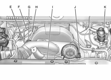
Engine Compartment Overview
5.3 L V8 Engine Shown (4.3 L V6 Engine, 4.8 L V8 Engine, 6.0 L V8 Engine, and 6.2 L V8 Engine Similar)
Chevrolet Silverado Owner Manual - 2012
Black plate (7,1)
A. Engine Air Cleaner/Filter on
H. Engine Oil Dipstick (Out of
page 10‑18.
B. Coolant Surge Tank and
Pressure Cap. See Cooling System on page 10‑20.
C. Positive (+) Terminal. See Jump
Starting on page 10‑96. D. Battery on page 10‑33. E. Remote Negative (−) Terminal
(Out of View). See Jump Starting on page 10‑96. F. Automatic Transmission
Dipstick (Out of View). See “Checking the Fluid Level” under Automatic Transmission Fluid (4-Speed Transmission) on page 10‑11 or Automatic Transmission Fluid (6-Speed Transmission) on page 10‑14.
View). See “Checking Engine Oil” under Engine Oil on page 10‑7. Engine Cooling Fan (Out of View). See Cooling System on page 10‑20.
I.
J. Power Steering Fluid Reservoir.
See Power Steering Fluid on page 10‑28.
K. Brake Master Cylinder
Reservoir. See Brake Fluid on page 10‑31.
L. Engine Compartment Fuse
Block on page 10‑49.
M. Windshield Washer Fluid
Reservoir. See “Adding Washer Fluid” under Washer Fluid on page 10‑29.
G. Engine Oil Fill Cap. See “When
to Add Engine Oil” under Engine Oil on page 10‑7.
If the vehicle has a diesel engine and/or an Allison Transmission, see the Duramax Diesel Supplement.
Vehicle Care
10-7
Engine Oil For diesel engine vehicles, see “Engine Oil” in the Duramax Diesel Supplement. To ensure proper engine performance and long life, careful attention must be paid to engine oil. Following these simple, but important steps will help protect your investment: . Always use engine oil approved to the proper specification and of the proper viscosity grade. See “Selecting the Right Engine Oil” in this section.
. Check the engine oil level regularly and maintain the proper oil level. See “Checking Engine Oil” and “When to Add Engine Oil” in this section.
. Change the engine oil at the
appropriate time. See Engine Oil Life System on page 10‑10. . Always dispose of engine oil
properly. See “What to Do with Used Oil” in this section.
Chevrolet Silverado Owner Manual - 2012
Black plate (8,1)
10-8
Vehicle Care
Checking Engine Oil It is a good idea to check the engine oil level at each fuel fill. In order to get an accurate reading, the vehicle must be on level ground. The engine oil dipstick handle is a yellow loop. See Engine Compartment Overview on page 10‑6 for the location of the engine oil dipstick. Obtaining an accurate oil level reading is essential: 1.
If the engine has been running recently, turn off the engine and allow several minutes for the oil to drain back into the oil pan. Checking the oil level too soon after engine shutoff will not provide an accurate oil level reading.
2. Pull out the dipstick and clean it with a paper towel or cloth, then push it back in all the way. Remove it again, keeping the tip down, and check the level.
When to Add Engine Oil
If the oil is below the cross-hatched area at the tip of the dipstick, add 1 L (1 qt) of the recommended oil and then recheck the level. See “Selecting the Right Engine Oil” in this section for an explanation of what kind of oil to use. For engine oil crankcase capacity, see Capacities and Specifications on page 12‑2.
Notice: Do not add too much oil. Oil levels above or below the acceptable operating range shown on the dipstick are harmful to the engine. If you find that you have an oil level above the operating range, i.e., the engine has so much oil that the oil level gets above the cross-hatched area that shows the proper operating range, the engine could be damaged. You should drain out the excess oil or limit driving of the vehicle and seek a service professional to remove the excess amount of oil. See Engine Compartment Overview on page 10‑6 for the location of the engine oil fill cap. Add enough oil to put the level somewhere in the proper operating range. Push the dipstick all the way back in when through.
Chevrolet Silverado Owner Manual - 2012
Black plate (9,1)
Selecting the Right Engine Oil Selecting the right engine oil depends on both the proper oil specification and viscosity grade. See Recommended Fluids and Lubricants on page 11‑13.
Specification Use and ask for licensed engine oils with the dexos1™ approved certification mark. Engine oils meeting the requirements for the vehicle should have the dexos™1
approved certification mark. This certification mark indicates that the oil has been approved to the dexos1
specification.Notice: Failure to use the recommended engine oil or equivalent can result in engine damage not covered by the vehicle warranty. Check with your dealer or service provider on whether the oil is approved to the dexos1 specification.
Viscosity Grade SAE 5W‐30 is the best viscosity grade for the vehicle. Do not use other viscosity grade oils such as SAE 10W‐30, 10W‐40, or 20W‐50.
Vehicle Care
10-9
If in an area of extreme cold, where the temperature falls below −20°F (−29°C), an SAE 0W‐30 oil should be used. An oil of this viscosity grade will provide easier cold starting for the engine at extremely low temperatures. When selecting an oil of the appropriate viscosity grade, always select an oil that meets the dexos1 specification or equivalent. See “Specification” for more information. Engine Oil Additives/Engine Oil Flushes Do not add anything to the oil. The recommended oils with the dexos specification and displaying the dexos certification mark are all that is needed for good performance and engine protection. Engine oil system flushes are not recommended and could cause engine damage not covered by the vehicle warranty.
Chevrolet Silverado Owner Manual - 2012
Black plate (10,1)
10-10
Vehicle Care
What to Do with Used Oil Used engine oil contains certain elements that can be unhealthy for your skin and could even cause cancer. Do not let used oil stay on your skin for very long. Clean your skin and nails with soap and water, or a good hand cleaner. Wash or properly dispose of clothing or rags containing used engine oil. See the manufacturer's warnings about the use and disposal of oil products. Used oil can be a threat to the environment. If you change your own oil, be sure to drain all the oil from the filter before disposal. Never dispose of oil by putting it in the trash or pouring it on the ground, into sewers, or into streams or bodies of water. Recycle it by taking it to a place that collects used oil.
Engine Oil Life System
When to Change Engine Oil This vehicle has a computer system that indicates when to change the engine oil and filter. This is based on a combination of factors which include engine revolutions, engine temperature, and miles driven. Based on driving conditions, the mileage at which an oil change is indicated can vary considerably. For the oil life system to work properly, the system must be reset every time the oil is changed. On some vehicles, when the system has calculated that oil life has been diminished, a CHANGE ENGINE OIL SOON message comes on to indicate that an oil change is necessary. See Engine Oil Messages on page 5‑46. Change the oil as soon as possible within the next 1 000 km (600 mi). It is possible that, if driving under the
best conditions, the oil life system might indicate that an oil change is not necessary for up to a year. The engine oil and filter must be changed at least once a year and, at this time, the system must be reset. For vehicles without the CHANGE ENGINE OIL SOON message, an oil change is needed when the OIL LIFE REMAINING percentage is near 0%. Your dealer has trained service people who will perform this work and reset the system. It is also important to check the oil regularly over the course of an oil drain interval and keep it at the proper level. If the system is ever reset accidentally, the oil must be changed at 5 000 km (3,000 mi) since the last oil change. Remember to reset the oil life system whenever the oil is changed.
Chevrolet Silverado Owner Manual - 2012
Black plate (11,1)
Vehicle Care
10-11
Automatic Transmission Fluid (4-Speed Transmission)
When to Check and Change Automatic Transmission Fluid A good time to check the automatic transmission fluid level is when the engine oil is changed. Change the fluid and filter at the intervals listed in Maintenance Schedule on page 11‑3 and be sure to use the transmission fluid listed in Recommended Fluids and Lubricants on page 11‑13.
How to Reset the Engine Oil Life System Reset the system whenever the engine oil is changed so that the system can calculate the next engine oil change. Always reset the engine oil life to 100% after every oil change. It will not reset itself. To reset the system on most vehicles: 1. Display the OIL LIFE
REMAINING on the DIC. If the vehicle does not have DIC buttons, the vehicle must be in P (Park) to access this display. See Driver Information Center (DIC) on page 5‑33.
2. Press and hold the SET/RESET
button on the DIC, or the trip odometer reset stem if the vehicle does not have DIC buttons, for more than five seconds. The oil life will change to 100%.
On all vehicles, the Engine Oil Life System can be reset as follows: 1. Turn the ignition to ON/RUN with
the engine off.
2. Fully press the accelerator pedal
slowly three times within five seconds.
3. Display the OIL LIFE
REMAINING on the DIC. If the display shows 100%, the system is reset. See Driver Information Center (DIC) on page 5‑33.
If the vehicle has a CHANGE ENGINE OIL SOON message and it comes back on when the vehicle is started and/or the OIL LIFE REMAINING is near 0%, the engine oil life system has not been reset. Repeat the procedure.
Chevrolet Silverado Owner Manual - 2012
Black plate (12,1)
10-12
Vehicle Care
How to Check Automatic Transmission Fluid Because this operation can be a little difficult, it may be best to have this done at the dealer service department. If not taken to the dealer, be sure to follow all the instructions here or a false reading on the dipstick could result. Notice: Too much or too little fluid can damage the transmission. Too much can mean that some of the fluid could come out and fall on hot engine parts or exhaust system parts, starting a fire. Too little fluid could cause the transmission to overheat. Be sure to get an accurate reading if checking the transmission fluid.
Wait at least 30 minutes before checking the transmission fluid level if you have been driving: . When outside temperatures are
above 32°C (90°F).
. At high speed for quite a while. In heavy traffic — especially in hot weather.
. While pulling a trailer. To get the right reading, the fluid should be at normal operating temperature, which is 82°C to 93°C (180°F to 200°F). Get the vehicle warmed up by driving about 24 km (15 miles) when outside temperatures are above 10°C (50°F). If it is colder than 10°C (50°F), drive the vehicle in 3 (Third) until the engine temperature gauge moves and then remains steady for 10 minutes.
A cold fluid check can be made after the vehicle has been sitting for eight hours or more with the engine off, but this is used only as a reference. Let the engine run at idle for five minutes if outside temperatures are 10°C (50°F) or more. If it is colder than 10°C (50°F), the engine may have to idle longer. Should the fluid level be low during this cold check, the fluid must be checked when hot before adding fluid. Checking the fluid hot will give you a more accurate reading of the fluid level.
Chevrolet Silverado Owner Manual - 2012
Black plate (13,1)
Checking the Fluid Level Prepare the vehicle as follows: 1. Park the vehicle on a level
place. Keep the engine running. 2. With the parking brake applied, place the shift lever in P (Park).
3. With your foot on the brake pedal, move the shift lever through each gear range, pausing for about three seconds in each range. Then, position the shift lever in P (Park).
4. Let the engine run at idle for
three minutes or more.
Vehicle Care
10-13
4. Check both sides of the dipstick,
and read the lower level. The fluid level must be in the COLD area, below the cross-hatched area, for a cold check or in the HOT or cross-hatched area for a hot check. Be sure to keep the dipstick pointed down to get an accurate reading. If the fluid level is in the acceptable range, push the dipstick back in all the way; then flip the handle down to lock the dipstick in place.
5.
Then, without shutting off the engine, follow these steps:
1. Locate the transmission dipstick handle with this graphic which is located at the rear of the engine compartment, on the passenger side of the vehicle. See Engine Compartment Overview on page 10‑6 for more information on location.
2. Flip the handle up, then pull out
the dipstick and wipe it with a clean rag or paper towel.
3. Push it back in all the way, wait
three seconds and then pull it back out again.
Chevrolet Silverado Owner Manual - 2012
Black plate (14,1)
10-14
Vehicle Care
Consistency of Readings Always check the fluid level at least twice using the procedure described previously. Consistency (repeatable readings) is important to maintaining proper fluid level. If readings are still inconsistent, contact the dealer. How to Add Automatic Transmission Fluid Refer to Recommended Fluids and Lubricants on page 11‑13 to determine what kind of transmission fluid to use. Using a funnel, add fluid down the transmission dipstick tube only after checking the transmission fluid while it is hot. A cold check is used only as a reference. If the fluid level is low, add only enough of the proper fluid to bring the level up to the HOT area for a hot check. It does not take much fluid, generally less than 0.5 Liter (1 Pint). Do not overfill.
Notice: Use of the incorrect automatic transmission fluid may damage the vehicle, and the damages may not be covered by the vehicle warranty. Always use the automatic transmission fluid listed in Recommended Fluids and Lubricants on page 11‑13. . After adding fluid, recheck the fluid level as described under “How to Check Automatic Transmission Fluid,” earlier in this section.
. When the correct fluid level is
obtained, push the dipstick back in all the way; then flip the handle down to lock the dipstick in place.
Automatic Transmission Fluid (6-Speed Transmission)
When to Check and Change Automatic Transmission Fluid It is usually not necessary to check the transmission fluid level. The only reason for fluid loss is a transmission leak or overheated transmission. If a small leak is suspected, then use the following checking procedures to check the fluid level. However, if there is a large leak, then it may be necessary to have the vehicle towed to a dealer service department and have it repaired before driving the vehicle further. Notice: Use of the incorrect automatic transmission fluid may damage the vehicle, and the damages may not be covered by the vehicle warranty. Always use the automatic transmission fluid listed in Recommended Fluids and Lubricants on page 11‑13.
Chevrolet Silverado Owner Manual - 2012
Black plate (15,1)
Change the fluid and filter at the scheduled maintenance intervals listed in Maintenance Schedule on page 11‑3. Be sure to use the transmission fluid listed in Recommended Fluids and Lubricants on page 11‑13. How to Check Automatic Transmission Fluid Notice: Too much or too little fluid can damage the transmission. Too much can mean that some of the fluid could come out and fall on hot engine parts or exhaust system parts, starting a fire. Too little fluid could cause the transmission to overheat. Be sure to get an accurate reading if checking the transmission fluid.
Before checking the fluid level, prepare the vehicle as follows: 1. Start the engine and park the
vehicle on a level surface. Keep the engine running.
2. Apply the parking brake and
place the shift lever in P (Park).
3. With your foot on the brake pedal, move the shift lever through each gear range, pausing for about three seconds in each range. Then, move the shift lever back to P (Park).
4. Allow the engine to idle
(500 – 800 rpm) for at least 1 minute. Slowly release the brake pedal.
5. Keep the engine running and
press the Trip/Fuel button or trip odometer reset stem until TRANS TEMP (Transmission Temperature) displays on the Driver Information Center (DIC).
Vehicle Care
10-15
6. Using the TRANS TEMP
reading, determine and perform the appropriate check procedure. If the TRANS TEMP reading is not within the required temperature ranges, allow the vehicle to cool, or operate the vehicle until the appropriate transmission fluid temperature is reached.
Cold Check Procedure Use this procedure only as a reference to determine if the transmission has enough fluid to be operated safely until a hot check procedure can be made. The hot check procedure is the most accurate method to check the fluid level. Perform the hot check procedure at the first opportunity.
Chevrolet Silverado Owner Manual - 2012
Black plate (16,1)
10-16
Vehicle Care
Use this cold check procedure to check fluid level when the transmission temperature is between 27°C and 32°C (80°F and 90°F).
3.
Install the dipstick by pushing it back in all the way; wait three seconds, and then pull it back out again.
4. Check both sides of the dipstick and read the lower level. Repeat the check procedure to verify the reading.
7.
6. Perform a hot check at
the first opportunity after the transmission reaches a normal operating temperature between 71°C to 93°C (160°F to 200°F). If the fluid level is in the acceptable range, push the dipstick back in all the way, then flip the handle down to lock the dipstick in place.
1. Locate the transmission dipstick
at the rear of the engine compartment, on the passenger side of the vehicle. See Engine Compartment Overview on page 10‑6 for more information.
2. Flip the handle up, then pull out
the dipstick and wipe it with a clean rag or paper towel.
5.
If the fluid level is below the COLD check band, add only enough fluid as necessary to bring the level into the COLD band. It does not take much fluid, generally less than 0.5 Liter (1 Pint). Do not overfill.
Hot Check Procedure Use this procedure to check the transmission fluid level when the transmission fluid temperature is between 71°C and 93°C (160°F and 200°F).
Chevrolet Silverado Owner Manual - 2012
Black plate (17,1)
The hot check is the most accurate method to check the fluid level. The hot check should be performed at the first opportunity in order to verify the cold check. The fluid level rises as fluid temperature increases, so it is important to ensure the transmission temperature is within range.
3.
Install the dipstick by pushing it back in all the way; wait three seconds, and then pull it back out again.
4. Check both sides of the dipstick and read the lower level. Repeat the check procedure to verify the reading.
6.
Vehicle Care
10-17
the HOT band. If the fluid level is low, add only enough fluid to bring the level into the HOT band. It does not take much fluid, generally less than 0.5 L (1 pint). Do not overfill. If the fluid level is in the acceptable range, push the dipstick back in all the way, then flip the handle down to lock the dipstick in place.
Consistency of Readings Always check the fluid level at least twice using the procedure described previously. Consistency (repeatable readings) is important to maintaining proper fluid level. If readings are still inconsistent, contact the dealer.
1. Locate the transmission dipstick
5. Safe operating level is within the
at the rear of the engine compartment, on the passenger side of the vehicle. See Engine Compartment Overview on page 10‑6 for more information.
2. Flip the handle up, then pull out
the dipstick and wipe it with a clean rag or paper towel.
HOT cross hatch band on the dipstick. If the fluid level is not within the HOT band, and the transmission temperature is between 71°C and 93°C (160°F and 200°F), add or drain fluid as necessary to bring the level into
Chevrolet Silverado Owner Manual - 2012
Black plate (18,1)
10-18
Vehicle Care
Manual Transmission Fluid It is not necessary to check the manual transmission fluid level. A transmission fluid leak is the only reason for fluid loss. If a leak occurs, take the vehicle to your dealer service department and have it repaired as soon as possible. See Recommended Fluids and Lubricants on page 11‑13 for the proper fluid to use.
Hydraulic Clutch It is not necessary to regularly check brake/clutch fluid unless you suspect there is a leak in the system. Adding fluid will not correct a leak. A fluid loss in this system could indicate a problem. Have the system inspected and repaired.
When to Check and What