- 2010 Chevrolet HHR Owners Manuals
- Chevrolet HHR Owners Manuals
- 2011 Chevrolet HHR Owners Manuals
- Chevrolet HHR Owners Manuals
- 2007 Chevrolet HHR Owners Manuals
- Chevrolet HHR Owners Manuals
- 2008 Chevrolet HHR Owners Manuals
- Chevrolet HHR Owners Manuals
- 2009 Chevrolet HHR Owners Manuals
- Chevrolet HHR Owners Manuals
- Download PDF Manual
-
the pressure from the parking pawl in the transmission, so you can pull the shift lever out of P (Park).
Leaving the Vehicle With the Engine Running (Automatic Transmission)
{ WARNING:
It can be dangerous to leave the vehicle with the engine running. The vehicle could move suddenly if the shift lever is not fully in P (Park) with the parking brake firmly set. And, if you leave the vehicle with the engine running, it could overheat and even catch fire. You or others could be injured. Do not leave the vehicle with the engine running.
If you have to leave an automatic transmission vehicle with the engine running, be sure the vehicle is in P (Park) and the parking brake is firmly set before you leave it. After you have moved the shift lever into P (Park), hold the brake pedal down. Then, see if you can move the shift lever away from P (Park) without first pushing the button. If you can, it means that the shift lever was not fully locked into P (Park).
3-36
Shifting Out of Park (Automatic Transmission) This vehicle is equipped with an electronic shift lock release system. The shift lock release is designed to: • Prevent ignition key removal unless the shift
lever is in P (Park) with the shift lever button fully released, and
• Prevent movement of the shift lever out of
P (Park) unless the ignition is in ON/RUN or ACC/ ACCESSORY and the regular brake pedal is applied.
The shift lock release is always functional except in the case of a an uncharged or low voltage (less than 9 volt) battery. If the vehicle has an uncharged battery or a battery with low voltage, try charging or jump starting the battery. See Jump Starting on page 6-40 for more information. To shift out of P (Park): 1. Apply the brake pedal. 2. Then press the shift lever button. 3. Move the shift lever to the desired position.
If you still are unable to shift out of P (Park): 1. Fully release the shift lever button. 2. While holding down the brake pedal, press the shift
lever button again.
3. Move the shift lever to the desired position. If you still cannot move the shift lever from P (Park), consult your dealer/retailer or a professional towing service.
Parking the Vehicle (Manual Transmission) Before leaving the vehicle, fully press the clutch pedal down, move the shift lever into R (Reverse), and firmly apply the parking brake. Once the shift lever has been placed in R (Reverse) with the clutch pedal pressed down, the ignition key can be turned to LOCK/OFF, then remove the key and release the clutch pedal. See Manual Transmission Operation on page 3-31.
3-37
Parking Over Things That Burn
{ WARNING:
Things that can burn could touch hot exhaust parts under the vehicle and ignite. Do not park over papers, leaves, dry grass, or other things that can burn.
Engine Exhaust
{ WARNING:
Engine exhaust contains Carbon Monoxide (CO) which cannot be seen or smelled. Exposure to CO can cause unconsciousness and even death. Exhaust may enter the vehicle if:
• The vehicle idles in areas with poor ventilation (parking garages, tunnels, deep snow that may block underbody airflow or tail pipes).
WARNING:
(Continued)
3-38
WARNING:
(Continued)
• The exhaust smells or sounds strange or
• The exhaust system leaks due to corrosion or
different.
damage.
• The vehicle’s exhaust system has been
modified, damaged or improperly repaired. • There are holes or openings in the vehicle
body from damage or after-market modifications that are not completely sealed. If unusual fumes are detected or if it is suspected that exhaust is coming into the vehicle:
• Drive it only with the windows
completely down.
• Have the vehicle repaired immediately.
Never park the vehicle with the engine running in an enclosed area such as a garage or a building that has no fresh air ventilation.
Running the Vehicle While Parked It is better not to park with the engine running. But if you ever have to, here are some things to know.
{ WARNING:
{ WARNING:
Idling a vehicle in an enclosed area with poor ventilation is dangerous. Engine exhaust may enter the vehicle. Engine exhaust contains Carbon Monoxide (CO) which cannot be seen or smelled. It can cause unconsciousness and even death. Never run the engine in an enclosed area that has no fresh air ventilation. For more information, see Engine Exhaust on page 3-38.
It can be dangerous to get out of the vehicle if the automatic transmission shift lever is not fully in P (Park) with the parking brake firmly set. The vehicle can roll. Do not leave the vehicle when the engine is running unless you have to. If you have left the engine running, the vehicle can move suddenly. You or others could be injured. To be sure the vehicle will not move, even when you are on fairly level ground, always set the parking brake and move the shift lever to P (Park).
Follow the proper steps to be sure the vehicle will not move. See Shifting Into Park (Automatic Transmission) on page 3-35. If parking on a hill and pulling a trailer, see Towing a Trailer (Automatic Transmission) on page 5-32 or Towing a Trailer (Manual Transmission) on page 5-40.
3-39
Automatic Dimming Mirror Operation Automatic dimming reduces the glare of lights from behind the vehicle. The dimming feature comes on and the indicator light illuminates each time the vehicle is started. Cleaning the Mirror Do not spray glass cleaner directly on the mirror. Use a soft towel dampened with water.
Compass Compass Operation Y / O (On/Off): If the vehicle has one of these buttons, press to turn the compass on or off. With the compass feature on, each time the vehicle is started, the compass displays the current compass direction after a few seconds.
Mirrors
Manual Rearview Mirror Hold the inside rearview mirror in the center to move it for a clearer view behind your vehicle. Adjust the mirror to avoid glare from the headlamps behind you. Push the tab forward for daytime use and pull it for nighttime use. If the vehicle has map lamps, press the buttons located at the bottom of the mirror to turn them on or off.
Automatic Dimming Rearview Mirror The vehicle may have an automatic dimming inside rearview mirror with a compass and map lights and/or OnStar®. Vehicles with OnStar have three additional control buttons located at the bottom of the mirror. See your dealer/retailer for more information on the system and how to subscribe to OnStar®. See the OnStar® owners guide for more information about the services OnStar provides. Press the buttons located at the bottom of the mirror to turn the map lights on or off. O (On/Off): Press to turn the dimming feature on or off.
3-40
Compass Calibration If after a few seconds the display does not show a compass direction, (N for North for example), there may be a strong magnetic field interfering with the compass. Interference can be caused by a magnetic antenna mount, note pad holder, or similar object. If CAL appears in the compass window, the compass may need to be reset or calibrated. To calibrate the compass: 1. Make sure CAL is displayed. If CAL is not displayed,
press and hold the compass button until CAL displays.
2. While CAL displays, drive the vehicle in circles at
5 mph (8 km/h) or less until the display reads a direction.
Compass Variance The mirror is set to zone eight. If you do not live in zone eight or drive out of the area, the compass variance needs to be changed to the appropriate zone.
To adjust for compass variance: 1. Find the current location and variance zone number
on the following zone map.
2. Press and hold the compass button until a Z and a
zone number displays.
3. Once the zone number displays, press the compass
button repeatedly until the correct zone number is reached. If CAL displays in the compass window, the compass may need calibration. See “Compass Calibration” listed previously.
3-41
Outside Power Mirrors
Outside Convex Mirror
Controls for the outside power mirrors are located on the driver door armrest.
{ WARNING:
A convex mirror can make things, like other vehicles, look farther away than they really are. If you cut too sharply into the right lane, you could hit a vehicle on the right. Check the inside mirror or glance over your shoulder before changing lanes.
1. Press the left or right side of the selector switch
located beneath the control pad, to select the driver or passenger mirror.
The passenger side mirror is convex shaped. A convex mirror’s surface is curved so more can be seen from the driver seat.
2. Press one of the four buttons located on the control
pad to move the mirror to the desired direction. 3. Adjust each outside mirror so that a little of the
vehicle and the area behind it can be seen.
Keep the selector switch in the center position when not adjusting either outside mirror. Manually fold the mirrors inward to prevent damage when going through an automatic car wash. To fold, push the mirror toward the vehicle. Push the mirror outward, to return to its original position.
3-42
Object Detection Systems
Rear Vision Camera (RVC) The vehicle may have a Rear Vision Camera system. Read this entire section before using it.
{ WARNING:
The Rear Vision Camera (RVC) system does not replace driver vision. RVC does not:
• Detect objects that are outside the camera’s
field of view, below the bumper, or underneath the vehicle.
• Detect children, pedestrians, bicyclists,
or pets.
Do not back the vehicle by only looking at the RVC screen, or use the screen during longer, higher speed backing maneuvers or where there could be cross-traffic. Your judged distances using the screen will differ from actual distances.
WARNING:
(Continued)
WARNING:
(Continued)
So if you do not use proper care before backing up, you could hit a vehicle, child, pedestrian, bicyclist, or pet, resulting in vehicle damage, injury, or death. Even though the vehicle has the RVC system, always check carefully before backing up by checking behind and around the vehicle.
The rear vision camera system is designed to help the driver when backing up by displaying a view of the area behind the vehicle. When the key is in the ON/RUN position and the driver shifts the vehicle into R (Reverse), the video image automatically appears on the inside rear view mirror. Once the driver shifts out of R (Reverse), the video image automatically disappears from the inside rear view mirror.
3-43
Rear Vision Camera Location The camera is located in the rear of the vehicle.
Turning the Rear Vision Camera System Off or On To turn off the rear vision camera system, press and hold z , located on the inside rearview mirror, until the left indicator light turns off. The rear vision camera display is now disabled. To turn the rear vision camera system on again, press and hold z until the left indicator light illuminates. The rear vision camera system display is now enabled and the display will appear in the mirror normally.
The area displayed by the camera is limited and does not display objects that are close to either corner or under the bumper. The area displayed can vary depending on vehicle orientation or road conditions. The distance of the image that appears on the screen differs from the actual distance. The following illustration shows the field of view that the camera provides.
3-44
When the System Does Not Seem To Work Properly The rear vision camera system might not work properly or display a clear image if: • The RVC is turned off. See “Turning the Rear
Camera System On or Off” earlier in this section.
• It is dark. • The sun or the beam of headlights is shining
directly into the camera lens.
• Ice, snow, mud, or anything else builds up on the
camera lens. Clean the lens, rinse it with water, and wipe it with a soft cloth.
• The back of the vehicle is in an accident, the
position and mounting angle of the camera can change or the camera can be affected. Be sure to have the camera and its position and mounting angle checked at your dealer/retailer.
• There are extreme temperature changes.
A. View displayed by the camera. B. Corner of the rear bumper.
3-45
Storage Areas
Glove Box Lift up on the glove box lever to open it.
Cupholders There are two cupholders located in the floor console between the front seats. There is also a cupholder for the rear seat passenger located at the rear of the floor console. Automatic transmission vehicles have a cupholder in front of the shift lever.
The rear vision camera system display in the rearview mirror may turn off or not appear as expected due to one of the following conditions. If this occurs the left indicator light on the mirror will flash. • A slow flash may indicate a loss of video signal, or
no video signal present during the reverse cycle.
• A fast flash may indicate that the display has been
on for the maximum allowable time during a reverse cycle, or the display has reached an Over Temperature limit. The fast flash conditions are used to protect the video device from high temperature conditions. Once conditions return to normal the device will reset and the green indicator will stop flashing.
During any of these fault conditions, the display will be blank and the indicator will continue to flash as long as the vehicle is in R (Reverse) or until the conditions return to normal.
Pressing and holding z when the left indicator light is flashing will turn off the video display along with the left indicator light.
3-46
Rear Storage Area
Instrument Panel Storage The vehicle has a storage compartment on the instrument panel above the air vents. Push the button on the compartment to open the cover.
Floor Console Storage Area There are two small storage compartments on the floor console.
The vehicle could also have two rear storage areas that can be used for small items.
3-47
Rear Compartment Storage Panel/Cover The vehicle could have an adjustable panel/cargo cover feature. The panel/cargo cover can be adjusted into four positions.
To use the panel in the lowest position: The panel can be used in this position if additional space above the panel is needed. Cargo can be placed on top of the panel in this position. 1. Insert the front corners of the panel into the lower
guides.
2. Slide the panel forward. 3. Press down on the back of the panel to lock it in
place.
{ WARNING:
If you were to carry things on the adjustable panel when it is in the upper (cargo cover) or center positions, during a sudden vehicle movement or a crash, those things could be thrown around in the vehicle. You or others could be injured. When it is in the upper or center position, always secure any cargo on the floor beneath the panel/cover.
3-48
To use the panel in the upper position as a cargo cover: 1. Insert the front corners of the panel into the top
guides.
2. Slide the panel forward. 3. Press down on the back of the panel to lock it in
place.
The center position is with the front corners placed in the lower guides and the rear corners placed in the upper guides. Do not load cargo on the panel in this position. The last position is with the front corners in the lower guides, panel sideways, closest to the rear seat for subfloor access. Do not drive while the panel is in this position. There are storage hooks on the bottom of the panel. The vehicle might have a cargo mat that covers the panel/cargo cover.
3-49
Roof Rack System The vehicle may have a roof rack system.
{ WARNING:
If something is carried on top of the vehicle that is longer or wider than the roof rack— like paneling, plywood, or a mattress— the wind can catch it while the vehicle is being driven. The item being carried could be violently torn off, and this could cause a collision, and damage the vehicle. Never carry something longer or wider than the roof rack on top of the vehicle unless using a GM Certified accessory carrier.
For vehicles with a roof rack, the rack can be used to load items. For roof racks that do not have crossrails included, GM Certified crossrails can be purchased as an accessory. See your dealer/retailer for additional information. Notice: Loading cargo on the roof rack that weighs more than 75 kg (165 lbs) or hangs over the rear or sides of the vehicle may damage the vehicle. Load cargo so that it rests evenly between the crossrails, making sure to fasten cargo securely.
3-50
Notice: Loading cargo directly on the roof of the vehicle may cause damage to the vehicle and would not be covered under warranty. Do not place cargo on the roof the vehicle. To prevent damage or loss of cargo when driving, check to make sure crossrails and cargo are securely fastened. Loading cargo on the roof rack will make the vehicle’s center of gravity higher. Avoid high speeds, sudden starts, sharp turns, sudden braking or abrupt maneuvers, otherwise it may result in loss of control. If driving for a long distance, on rough roads, or at high speeds, occasionally stop the vehicle to make sure the cargo remains in its place. Do not exceed the maximum vehicle capacity when loading the vehicle. For more information on vehicle capacity and loading, see Loading the Vehicle on page 5-24.
Convenience Net The vehicle may have a convenience net. The metal rings in the cargo area can be used to attach the convenience net for several uses. The net can be used to attach items secured to the floor, to the rear liftgate or liftgate glass. The net is not for larger, heavier loads.
Hideaway Rear Storage Bins
The vehicle may have two storage bins located in the rear of the vehicle. Pull up on the handles to open and lift the lid. Use the key to lock/unlock the bins.
There is a rod that hooks into place to prop open the lid. Push the rod towards the lid to unhook it and lower the lid.
3-51
Sunroof The vehicle may have a power sunroof.
The switches that operate the sunroof are located in the headliner.
To open or close the sunroof, the ignition must be in ON/RUN, ACC/ACCESSORY, or Retained Accessory Power (RAP) must be active. See Retained Accessory Power (RAP) on page 3-25. Express Open: To express open the power sunroof, fully press the driver’s side switch rearward once. To stop the sunroof glass in a desired position other than to the express-open position, press the switch again, in either direction, to stop the movement. If the sunshade is in the closed position, it will open with the sunroof, or it can be opened manually.
3-52
Vent Open: To open to the vent position from the closed position, press and hold the passenger’s side sunroof switch forward. The rear of the sunroof panel will tilt upward to the full vent position. The sunshade must be opened manually. Express Close: To express close the power sunroof, fully press the driver’s side switch forward once. To stop the sunroof glass in a desired position other than closed, press the switch again in either direction. The sunshade must be closed manually. Close: To close the power sunroof, operate the controls according to one of the following: • From the open position, press and hold the driver’s side sunroof switch forward. The sunshade must be closed manually.
• From the vent position, press and hold the passenger’s side sunroof switch rearward.
Anti-Pinch: If an object is in the path of the sunroof while it is closing, the anti-pinch feature will detect the object and stop the sunroof from closing at the point of the obstruction. The sunroof will then return to the full-open or vent position. To close the sunroof once it has re-opened, refer to the two options previously described under the “Close” feature instructions.
Section 4
Instrument Panel
Instrument Panel Overview ...............................4-3
Hazard Warning Flashers ................................4-3
Horn .............................................................4-3
Tilt Wheel .....................................................4-3
Turn Signal/Multifunction Lever .........................4-4
Turn and Lane-Change Signals ........................4-4
Headlamp High/Low-Beam Changer ..................4-5
Flash-to-Pass .................................................4-5
Windshield Wipers ..........................................4-5
Windshield Washer .........................................4-6
Rear Window Wiper/Washer .............................4-7
Cruise Control ................................................4-8
Headlamps ..................................................4-11
Wiper Activated Headlamps ............................4-11
Headlamps on Reminder ................................4-12
Daytime Running Lamps (DRL) .......................4-12
Automatic Headlamp System ..........................4-12
Fog Lamps ..................................................4-13
Instrument Panel Brightness ...........................4-14
Dome Lamp .................................................4-14
Entry/Exit Lighting .........................................4-14
Reading Lamps ............................................4-14
Electric Power Management ...........................4-15
Battery Run-Down Protection ..........................4-15
Accessory Power Outlet(s) .............................4-16
Ashtray(s) and Cigarette Lighter ......................4-18Climate Controls ............................................4-18
Climate Control System .................................4-18
Outlet Adjustment .........................................4-21
Passenger Compartment Air Filter ...................4-21
Warning Lights, Gages, and Indicators ............4-23
Instrument Panel Cluster ................................4-24
Speedometer and Odometer ...........................4-25
Tachometer .................................................4-25
Safety Belt Reminders ...................................4-26
Airbag Readiness Light ..................................4-27
Passenger Airbag Status Indicator ...................4-28
Charging System Light ..................................4-29
Up-Shift Light ...............................................4-29
Brake System Warning Light ..........................4-30
Antilock Brake System (ABS) Warning Light .....4-31
Enhanced Traction System (ETS) Indicator/Warning Light ...........................................4-32
Electronic Stability Control (ESC)/Traction Control System (TCS) Indicator/Warning Light ........................................................4-32
Engine Coolant Temperature Warning Light ......4-33
Engine Coolant Temperature Gage ..................4-34
Tire Pressure Light .......................................4-34
Malfunction Indicator Lamp .............................4-35
Oil Pressure Light .........................................4-38
Security Light ...............................................4-384-1
Section 4
Instrument Panel
Fog Lamp Light ............................................4-38
Highbeam On Light .......................................4-39
Fuel Gage ...................................................4-39
Boost Gage .................................................4-40
Reconfigurable Performance Display (RPD) ......4-40
Driver Information Center (DIC) .......................4-46
DIC Operation and Displays ...........................4-46
DIC Warnings and Messages .........................4-48
DIC Vehicle Personalization ............................4-54Audio System(s) .............................................4-60
Setting the Clock ..........................................4-61
Radio(s) ......................................................4-62
Using an MP3 ..............................................4-74
XM Radio Messages .....................................4-80
Bluetooth® ...................................................4-82
Theft-Deterrent Feature ..................................4-92
Audio Steering Wheel Controls .......................4-92
Radio Reception ...........................................4-93
Fixed Mast Antenna ......................................4-94
XM™ Satellite Radio Antenna System .............4-94
Chime Level Adjustment ................................4-944-2
Tilt Wheel A tilt wheel lets the steering wheel be adjusted before driving.
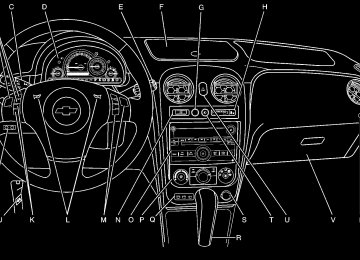
Instrument Panel Overview
Hazard Warning Flashers | (Hazard Warning Flasher): Press this button located on the instrument panel, to make the front and rear turn signal lamps flash on and off. This warns others that you are having trouble. Press | again to turn the flashers off.
Horn To sound the horn, press the horn symbols located on the steering wheel.
The tilt lever is located on the left side of the steering column. To tilt the wheel, pull the lever down. Then, move the wheel to a comfortable position and raise the lever to lock the wheel in place. Do not adjust the steering wheel while driving.
4-3
Turn Signal/Multifunction Lever
Turn and Lane-Change Signals
An arrow on the instrument panel cluster flashes in the direction of the turn or lane change.
The lever on the left side of the steering column operates the following: G : Turn and Lane-Change Signals 5 3: Headlamp High/Low-Beam Changer O : Exterior Lamp Control Flash-to-Pass. Information for these features is on the pages following.
Move the lever all the way up or down to signal a turn. Raise or lower the lever until the arrow starts to flash to signal a lane change. Hold it there until the lane change is complete. The lever returns to its starting position when it is released. If after signaling a turn or a lane change the arrows flash rapidly or do not come on, a signal bulb could be burned out. Have the bulbs replaced. If the bulb is not burned out, check the fuse. See Fuses and Circuit Breakers on page 6-115.
4-4
Headlamp High/Low-Beam Changer To change the headlamps from low beam to high beam, push the turn signal lever away from you.
Windshield Wipers
This indicator light appears on the instrument panel cluster when the high beams are on.
To change the headlamps from high beam to low beam, pull the turn signal lever toward you. Flash-to-Pass To signal to a driver in front of you that you want to pass, pull the turn signal/multifunction lever until the high-beam headlamps come on. Then release the lever to turn them off.
The windshield wiper lever is on the right side of the steering wheel. Move the lever to one of the following positions: 1 (High Speed): Fast wipes. 6 (Low Speed): Slow wipes. & (Delay): Sets a delay between wipes.
4-5
Windshield Washer To wash the windshield, press the button at the end of the lever until the washers begin.
{ WARNING:
In freezing weather, do not use your washer until the windshield is warmed. Otherwise the washer fluid can form ice on the windshield, blocking your vision.
When the button is released, the washers will stop, but the wipers will continue to wipe for about three times or will resume the speed being used before.
6 (Delay/Intermittent Speed Sensitive): When the lever is in the delay position, turn the band up for more frequent wipes or down for less frequent wipes.
During intermittent wiping mode, the delay cycle time is sensitive to vehicle speed. As the vehicle speed increases the delay cycle time decreases and wiper movement occurs more frequently. 9 (Off): Turns the windshield wipers off. 8 (Mist): Single wipe, move the lever to z and then release it. Several wipes, hold lever on z longer. As an added safety feature, if the wipers are on for more than 15 seconds, the vehicle’s headlamps turn on automatically. They turn off 15 seconds after the wipers are turned off. Clear snow and ice from the wiper blades before using them. If frozen to the windshield, carefully loosen or thaw them. Damaged wiper blades should be replaced. See Windshield Wiper Blade Replacement on page 6-53. Heavy snow or ice can overload the wiper motor. A circuit breaker will stop the motor until it cools down.
4-6
Rear Window Wiper/Washer
The rear window washer/wiper button is located on the instrument panel below the climate controls.
{ WARNING:
In freezing weather, do not use your washer until the windshield is warmed. Otherwise the washer fluid can form ice on the windshield, blocking your vision.
5 (Delay): Press to turn on the intermittent wiping setting that has a longer delay.
Y (Washer Fluid): Press to wash and wipe the window.
The rear window washer uses the same fluid reservoir as the windshield washer. However, the rear window washer will run out of fluid before the windshield washer. If the windshield can be washed, but not the rear windows, check the fluid level.
Z (Rear Wiper): Press to turn on an intermittent setting that has a shorter delay. To turn either of the intermittent wiper settings off, press the opposite side of the button to turn it to the off position. Press the button all the way down on either side to activate an intermittent wiper setting.
4-7
Cruise Control With cruise control, a speed of about 40 km (25 mph) or more can be maintained without keeping your foot on the accelerator. Cruise control does not work at speeds below 40 km (25 mph). The brake must be applied at least one time, after the vehicle has been started, before cruise control will function.
{ WARNING:
Cruise control can be dangerous where you cannot drive safely at a steady speed. So, do not use the cruise control on winding roads or in heavy traffic. Cruise control can be dangerous on slippery roads. On such roads, fast changes in tire traction can cause excessive wheel slip, and you could lose control. Do not use cruise control on slippery roads.
Setting Cruise Control
{ WARNING:
If you leave your cruise control on when you are not using cruise, you might hit a button and go into cruise when you do not want to. You could be startled and even lose control. Keep the cruise control switch off until you want to use cruise control.
The cruise control buttons are located on the left side of the steering wheel.
4-8
J (On/Off): Press to turn the cruise control system on and off. The indicator light on the button comes on when the cruise control is on and goes off when the cruise control is turned off.
RES+ (Resume): Press to resume a set speed and to accelerate the speed. SET− (Set): Press to set a speed and to decrease the speed. To set a speed: 1. Press I to turn cruise control on. The indicator
light on the button comes on.
2. Get to the desired speed. 3. Press the SET− control button and release it. The CRUISE ENGAGED message appears on the Driver Information Center (DIC) to show the system is engaged.
4. Take your foot off the accelerator pedal.
When the brakes are applied or the clutch pedal is used, the cruise control shuts off. If the vehicle is in cruise control and the Traction Control System (TCS) begins to limit wheel spin, the cruise control automatically disengages. See Traction Control System (TCS) on page 5-9 and Enhanced Traction System (ETS) on page 5-11. When road conditions allow, the cruise control can be used again. Resuming a Set Speed Suppose the cruise control is set at a desired speed and then the brake is applied. This disengages the cruise control. To return to the previously set speed, it is not necessary to go through the set process again. Once the vehicle is going about 40 km (25 mph) or more, press the RES+ part of the button briefly. The vehicle goes back to the previously set speed.
4-9
Increasing Speed While Using Cruise Control There are two ways to go to a higher speed. 1. Disengage the cruise control by applying the brake pedal, but do not turn it off. Accelerate to a higher speed and reset the cruise control.
2. If the cruise control system is already engaged,
press the RES+ button. Hold it there until the desired speed is reached, and then release the button. To increase the vehicle speed in small amounts, press the RES+ button briefly and then release it. Each time this is done, the vehicle goes about 1.6 km/h (1 mph) faster.
Reducing Speed While Using Cruise Control If the cruise control system is already engaged, • Push and hold the SET− button until the lower
speed desired is reached, then release it. • To slow down in small amounts, push the
SET− button briefly. Each time this is done, the vehicle goes about 1.6 km/h (1 mph) slower.
Passing Another Vehicle While Using Cruise Control Use the accelerator pedal to increase the vehicle speed. When you take your foot off the pedal, the vehicle slows down to the cruise control speed you set earlier. Using Cruise Control on Hills How well the cruise control works on hills depends upon the vehicle speed, load and the steepness of the hills. When going up steep hills, the accelerator pedal might need to be applied to maintain the vehicle speed. When going downhill, the brake might need to be applied or the vehicle might have to be shifted to a lower gear to keep the vehicle speed down. When the brakes are applied the cruise control turns off. Ending Cruise Control To end cruise control, step lightly on the brake pedal or the clutch pedal if the vehicle has a manual transmission. Stepping on the brake pedal or clutch pedal will only end the current cruise control session. Press I to turn the system completely off. Erasing Speed Memory The cruise control set speed memory is erased when the cruise control or the ignition is turned off.
4-10
Headlamps
The lever on the left side of the steering column operates the exterior lamps. The exterior lamp switch has the following four positions: 2 (Headlamps): Turns on the headlamps, parking lamps, and taillamps. ; (Parking Lamps): Turns on the parking lamps and taillamps only. AUTO (Automatic Headlamp System): Automatically turns on the Daytime Running Lamps during daytime, and the headlamps, parking lamps, and taillamps at night.
P (Off/On): This position is the momentary Off/On switch for the Automatic Headlamp System. In Canada, this only works when the vehicles with an automatic transmission are in P (Park) and vehicles with a manual transmission have the parking brake set and the vehicle is not moving. When operating in AUTO, a momentary turn of the switch to off/on will turn off the Automatic Headlamp System. An AUTO LIGHTS OFF message displays on the Driver Information Center (DIC) and a chime will sound. Turning the switch to off/on again will turn the Automatic Headlamp System back on. An AUTO LIGHTS ON message displays on the DIC. The Automatic Headlamp System is always turned on at the beginning of an ignition cycle for vehicles with manual transmission.
Wiper Activated Headlamps The headlamps and parking lamps are activated 15 seconds after the windshield wipers are turned on. For this feature to work, automatic lighting must be enabled. See Headlamps on page 4-11 for additional information. When the ignition is turned off, the wiper-activated headlamps will immediately turn off. They also turn off 15 seconds after the windshield wiper control is turned off.
4-11
Headlamps on Reminder If the drivers door is opened with the ignition off and the lamps on, a warning chime will sound. This indicates that the headlamps are still on.
Daytime Running Lamps (DRL) Daytime Running Lamps (DRL) can make it easier for others to see the front of your vehicle during the day. Fully functional daytime running lamps are required on all vehicles first sold in Canada. The vehicle has a light sensor on top of the instrument panel. Do not cover this sensor or the headlamps will come on when they are not needed. The DRL system will make the headlamps come on at reduced brightness when the following conditions are met: • The ignition is on. • The exterior lamp control is turned to AUTO. • The light sensor detects daytime light. • The shift lever is not in P (Park). While the DRL system is on, the taillamps, sidemarker lamps, and instrument panel lights will not be on.
4-12
For vehicles with an Automatic Transmission, the DRL system is off any time the vehicle is in P (Park). For vehicles with a Manual Transmission, the DRL system will be off when the vehicle is first started, the park brake is applied, and the vehicle has not moved. The DRL system on U.S. vehicles can also be turned off by using the off/on switch for one ignition cycle. The regular headlamp system should be turned on when needed.
Automatic Headlamp System When it is dark enough outside, the automatic system turns on the headlamps at the normal brightness along with other lamps such as the taillamps, sidemarker, parking lamps, instrument panel lights, and interior switch backlighting. Do not cover the light sensor, located on top of the instrument panel. If the sensor is covered the headlamps may remain on when they are not needed. If the vehicle is driven through a parking garage, overcast weather or a tunnel, the automatic headlamp system may turn on.
There is a delay in the transition between the daytime and nighttime operation of the automatic lamp control system so that driving under bridges or bright overhead street lights does not affect the system. The automatic lamp control system will only be affected when the light sensor sees a change in lighting lasting longer than this delay. If the vehicle is started in a dark garage, the automatic lamp system turns on immediately. Once the vehicle exits the garage, it will take about 20 seconds for the automatic lamp system to change to DRL if it is light outside. During that delay, the instrument panel cluster may not be as bright as usual. Make sure the instrument panel brightness control is in the full bright position. See Instrument Panel Brightness on page 4-14. To idle the vehicle with the system off, turn the ignition on and turn the exterior light switch to the off/on position. For vehicles first sold in Canada, the transmission must stay in P (Park) for this function or the parking brake must be set for vehicles with manual transmissions. Turn on the regular headlamps when they are needed.
Fog Lamps For vehicles with fog lamps, the button is located on the instrument panel, to the right of the steering wheel. The ignition must be on to use the fog lamps.
# : Press to turn the fog lamps on and off. An indicator light on the button comes on when the fog lamps are on.
The parking lamps automatically turn on and off when the fog lamps are turned on and off.
The fog lamps will turn off while the high-beam headlamps are turned on. Some localities have laws that require the headlamps to be on along with the fog lamps.
4-13
Instrument Panel Brightness
The control for this feature is located to the right of the steering wheel and above the radio.
Move the thumbwheel to the left to dim the lights or to the right to brighten the lights. The dome lamps will turn on when the thumbwheel is moved completely to the right. Dome Lamp The dome lamps turn on when any door is opened. To turn on all dome lamps with the doors closed, turn the instrument panel brightness thumbwheel completely to the right. See Instrument Panel Brightness on page 4-14.
Entry/Exit Lighting The lamps inside the vehicle turn on when any door is opened. These lamps will fade out after about 20 seconds after all of the doors have been closed or when the ignition is turned to ON/RUN. These lamps will also turn on when pressing the unlock symbol button or the horn symbol on the keyless entry system transmitter. The lamps inside the vehicle will stay on for about 20 seconds after the key is removed from the ignition to provide an illuminated exit.
Reading Lamps There are reading lamps located on the front and rear dome lamps. To turn the front reading lamps on or off, press the lamp lens. To turn the rear reading lamps on or off, press the button next to the lamp.
4-14
Electric Power Management This vehicle has Electric Power Management (EPM), an advanced control system. It estimates the battery’s temperature and state of charge and then adjusts the voltage for best performance and extended life of the battery. When the battery’s state of charge is low, the voltage is raised slightly to quickly put the charge back in. When the state of charge is high, the voltage is lowered slightly to prevent overcharging. If the vehicle has a voltmeter gage or voltage display on the Driver Information Center (DIC), you may see the voltage move up or down. This is normal. If there is a problem, an alert will be displayed. The battery can be discharged at idle if the electrical loads are very high. This is true for all vehicles. This is because the generator (alternator) may not be spinning fast enough at idle to produce all the power that is needed for very high electrical loads. A high electrical load occurs when several of the following loads are on: headlamps, high beams, fog lamps, rear window defogger, climate control fan at high speed, heated seats, engine cooling fans, trailer loads, and loads plugged into accessory power outlets.
EPM works to prevent excessive discharge of the battery. It does this by balancing the generator’s output and the vehicle’s electrical needs. It can increase engine idle speed to generate more power, whenever needed. It can temporarily reduce the power demands of some accessories. Normally, these actions occur in steps or levels, without being noticeable. In rare cases at the highest levels of corrective action, this action may be noticeable to the driver.
Battery Run-Down Protection The vehicle has a battery saver feature designed to protect the vehicle’s battery. When any interior lamp is left on and the ignition is turned off, the battery rundown protection system automatically turns the lamp off after 20 minutes. This prevents draining of the battery.
4-15
Accessory Power Outlet(s) Accessory power outlets can be used to connect electrical equipment, such as a cellular phone. The accessory power outlets are located on the instrument panel below the climate controls and at the rear of the center console. There may be an outlet in the rear cargo area on the passenger side. To use the outlet, remove the cover. While not in use, always cover the outlet with the protective cap. Notice: Leaving electrical equipment plugged in for an extended period of time while the vehicle is off will drain the battery. Power is always supplied to the outlets. Always unplug electrical equipment when not in use and do not plug in equipment that exceeds the maximum 20 ampere rating.
Certain electrical accessories may not be compatible with the accessory power outlet and could result in blown vehicle or adapter fuses. If you experience a problem, see your dealer/retailer for additional information on the accessory power outlet. Notice: Adding any electrical equipment to the vehicle can damage it or keep other components from working as they should. The repairs would not be covered by the vehicle warranty. Do not use equipment exceeding maximum amperage rating of 20 amperes. Check with your dealer/retailer before adding electrical equipment. When adding electrical equipment, be sure to follow the installation instructions included with the equipment. Notice: cause damage not covered by the vehicle warranty. Do not hang any type of accessory or accessory bracket from the plug because the power outlets are designed for accessory power plugs only.
Improper use of the power outlet can
4-16
Rear Power Plug for Converters
The vehicle may have a power plug connector located in the rear cargo area on the passenger side behind the service panel. The power connector wiring can be accessed by removing the service panel to begin installation.
This plug can be used to supply power to commercial converters and contains four different circuits. The functions of these circuits are as follows; a 40 Amp battery service, a 10 Amp Accessory or Run service, a 15 Amp Delayed Accessory service and a Ground circuit. Notice: Adding any electrical equipment to your vehicle may damage it or keep other components from working as they should. The repairs would not be covered by your warranty. Do not use equipment exceeding maximum amperage rating of 40 amperes. Check with your dealer/retailer before adding electrical equipment. When adding electrical equipment, be sure to follow the installation instructions included with the equipment. Notice: cause damage not covered by the vehicle warranty. Do not hang any type of accessory or accessory bracket from the plug because the power outlets are designed for accessory power plugs only. Notice: Leaving electrical equipment plugged in for an extended period of time while the vehicle is off will drain the battery. Power is always supplied to the outlets. Always unplug electrical equipment when not in use and do not plug in equipment that exceeds the maximum 40 ampere rating.
Improper use of the power outlet can
4-17
Ashtray(s) and Cigarette Lighter The vehicle may have an ashtray and cigarette lighter. To use the lighter, located on the instrument panel below the climate controls, push it in all the way and let go. When it is ready, it will pop back out by itself. Notice: Holding a cigarette lighter in while it is heating will not allow the lighter to back away from the heating element when it is hot. Damage from overheating may occur to the lighter or heating element, or a fuse could be blown. Do not hold a cigarette lighter in while it is heating. Do not use equipment exceeding maximum amperage rating of 15 amperes. To clean the center console ashtray, remove the entire ashtray and empty it. Notice: are put in the ashtray, hot cigarettes or other smoking materials could ignite them and possibly damage the vehicle. Never put flammable items in the ashtray.
If papers, pins, or other flammable items
4-18
Climate Controls
Climate Control System The heating, cooling, and ventilation for the vehicle can be controlled with this system. For vehicles with remote start, the climate control system comes on and uses the prior temperature settings selected before exiting the vehicle.
A. Temperature
Control
B. Fan Control C. Air Delivery Mode
Control
D. Air Conditioning E. Outside Air F. Air Recirculation G. Rear Window
Defogger
9 (Off): Turn the fan control to this position to turn the fan off.
Temperature Control: Turn clockwise or counterclockwise to increase or decrease the temperature. 9 (Fan): Turn clockwise or counterclockwise to increase or decrease the fan speed. In any setting other than off, the fan runs continuously while the ignition is in ON/RUN. The fan must be turned on to run the air conditioning (AC) compressor.
Air Delivery Mode Control: Turn clockwise or counterclockwise to change the direction of the airflow inside the vehicle.
To change the current mode, select: H (Vent): Air is directed to the instrument panel outlets. ) (Bi-Level): Air is divided between the instrument panel outlets and the floor outlets. 6 (Floor): Air is directed to the floor outlets, with some air directed to the windshield and side windows.
- (Defog): This mode clears the windows of fog or moisture. Air is directed to the windshield, side window, and floor outlets. In this mode, the system runs the air conditioning compressor. To defog the windows faster, turn the temperature control knob clockwise to the warmest setting. 0 (Defrost): This mode removes fog or frost from the windshield more quickly. Air is directed to the windshield, with some air directed to the side window and floor outlets. In this mode, the system runs the air conditioning compressor. To defrost the windows faster, turn the temperature control knob clockwise to the warmest setting. # (Air Conditioning): Press to turn the air conditioning system on or off. An indicator light comes on to show that the air conditioning is on. On hot days, open the windows to let hot inside air escape; then close them. This helps to reduce the time it takes for your vehicle to cool down. It also helps the system to operate more efficiently.
4-19
For quick cool down on hot days: 1. Select H . 2. Select @ . 3. Select # . 4. Select the coolest temperature. 5. Select the highest fan speed. Using these settings together for long periods of time can cause the air inside of the vehicle to become too dry. To prevent this from happening, after the air in the vehicle has cooled, turn off the recirculation by pressing the outside air button. The air conditioning system removes moisture from the air, so a small amount of water might drip under the vehicle while idling or after turning off the engine. This is normal. The air conditioning compressor cannot be turned on when the fan is off. @ (Recirculation): Press to turn the recirculation mode on. An indicator light comes on to show that recirculation is on.
This mode recirculates and helps to quickly cool the air inside the vehicle. It can be used to help prevent outside air and odors from entering the vehicle.
The air conditioning compressor also comes on. Recirculation is not available in floor, defog and defrost modes. If the recirculation button is pressed, the indicator light flashes five times and outside air is delivered. Operation in this mode during periods of high humidity and cool outside temperatures can result in increased window fogging. If window fogging is experienced, select the defrost mode. ; (Outside Air): Press to allow outside air to circulate through the vehicle. An indicator light comes on to show that outside air is on. Rear Window Defogger The rear window defogger uses a warming grid to remove fog from the rear window. The rear window defogger only works when the ignition is in ON/RUN. < (Rear): Press to turn the rear window defogger on or off. Be sure to clear as much snow from the rear window as possible. An indicator light comes on to show that the rear window defogger is on.
4-20
The rear window defogger turns off approximately 15 minutes after the button is pressed. If turned on again, the defogger only runs for approximately seven minutes before turning off. If the vehicle speed is greater than 80 km/h (50 mph) and the rear defogger is on, it remains on as long as the speed is greater than 80 km/h (50 mph). The defogger can also be turned off by turning off the engine. For vehicles with the remote start feature, the rear defogger automatically turns on if it is cold outside. When the vehicle transitions out of the remote start mode, the rear defogger turns off. See Remote Keyless Entry (RKE) System Operation on page 3-4
Notice: Do not use anything sharp on the inside of the rear window. If you do, you could cut or damage the warming grid, and the repairs would not be covered by the vehicle warranty. Do not attach a temporary vehicle license, tape, a decal or anything similar to the defogger grid.Outlet Adjustment Turn the outlets and move the outlet vanes to change the direction of the airflow and to open and close the outlets. Operation Tips • Clear away any ice, snow or leaves from the air
inlets at the base of the windshield that may block the flow of air into the vehicle.
• Use of non-GM approved hood deflectors may adversely affect the performance of the system.
• Keep the path under the front seats clear of objects
to help circulate the air inside of the vehicle more effectively.
Passenger Compartment Air Filter The filter removes dust and pollen from the air which is drawn into the vehicle. Airflow reduction is an indication that the filter needs to be replaced. The filter should be replaced as part of routine scheduled maintenance. See Scheduled Maintenance on page 7-3 for replacement intervals. To find out what type of filter to use, see Maintenance Replacement Parts on page 7-12.
4-21
To access the passenger compartment air filter: 1. Open and empty the glove box.
2. Press both glove box stops outward to let the glove
box drop open completely.
3. Pull the three tabs of the filter access door down
and open the access door downward.
4-22
4. Pull the filter out, keeping it upwards. Install the new air filter with the AIR FLOW arrow pointing downward. Reverse Steps 1 through 4 to reassemble.
Warning Lights, Gages, and Indicators Warning lights and gages can signal that something is wrong before it becomes serious enough to cause an expensive repair or replacement. Paying attention to the warning lights and gages could prevent injury. Warning lights come on when there might be or there is a problem with one of the vehicle’s functions. Some warning lights come on briefly when the engine is started to indicate they are working. Gages can indicate when there might be or there is a problem with one of the vehicle’s functions. Often gages and warning lights work together to indicate a problem with the vehicle. When one of the warning lights comes on and stays on while driving, or when one of the gages shows there could be a problem, check the section that explains what to do. Follow this manual’s advice. Waiting to do repairs can be costly and even dangerous.
4-23
Instrument Panel Cluster
United States Manual Transmission Cluster shown, Automatic, SS and Canada similar
4-24
Speedometer and Odometer The speedometer shows the speed in both kilometers per hour (km/h) and miles per hour (mph). The vehicle’s odometer works together with the Driver Information Center (DIC). Trip A and Trip B can be set on the odometer. See “Trip Information” under DIC Operation and Displays on page 4-46. The vehicle does not have to be running to check the odometer mileage. Simply open the driver’s door and the mileage briefly displays. If the vehicle ever needs a new odometer installed, the new one will be set to the correct total mileage of the old odometer.
Tachometer
The tachometer displays the engine speed in revolutions per minute (rpm).
If the engine is operated with the tachometer
Notice: in the red warning area, the vehicle could be damaged and the damages would not be covered by the vehicle warranty. Do not operate the engine with the tachometer in the red warning area.
4-25
Safety Belt Reminders Driver Safety Belt Reminder Light When the engine is started, a chime sounds for several seconds to remind a driver to fasten the safety belt, unless the driver safety belt is already buckled.
The safety belt light comes on and stays on for several seconds, then flashes for several more.
Passenger Safety Belt Reminder Light For vehicles equipped with the passenger safety belt reminder light, several seconds after the engine is started, a chime sounds for several seconds to remind the front passenger to buckle their safety belt. The passenger safety belt light, located on the instrument panel, comes on and stays on for several seconds and then flashes for several more.
This chime and light are repeated if the passenger remains unbuckled and the vehicle is in motion.
This chime and light are repeated if the driver remains unbuckled and the vehicle is in motion. If the driver safety belt is already buckled, neither the chime nor the light comes on.
If the passenger safety belt is buckled, neither the chime nor the light comes on. The front passenger safety belt warning light and chime may turn on if an object is put on the seat such as a briefcase, handbag, grocery bag, laptop or other electronic device. To turn off the warning light and or chime, remove the object from the seat or buckle the safety belt.
4-26
Airbag Readiness Light The system checks the airbag’s electrical system for possible malfunctions. If the light stays on it indicates there is an electrical problem. The system check includes the airbag sensor, the pretensioners, the airbag modules, the wiring and the crash sensing and diagnostic module. For more information on the airbag system, see Airbag System on page 2-58.
The airbag readiness light flashes for a few seconds when the engine is started. If the light does not come on then, have it fixed immediately.
{ WARNING:
If the airbag readiness light stays on after the vehicle is started or comes on while driving, it means the airbag system might not be working properly. The airbags in the vehicle might not inflate in a crash, or they could even inflate without a crash. To help avoid injury, have the vehicle serviced right away.
If there is a problem with the airbag system, an airbag Driver Information Center (DIC) message can also come on. See DIC Warnings and Messages on page 4-48
for more information.4-27
Passenger Airbag Status Indicator If the vehicle has one of the passenger airbag status indicators pictured in the following illustrations, then the vehicle has a passenger sensing system for the right front passenger position. The passenger airbag status indicator, if equipped, is on the instrument panel. See Passenger Sensing System on page 2-68 for important safety information. In addition, if the vehicle has a passenger sensing system for the right front passenger position, the label on the vehicle’s sun visors refer to “ADVANCED AIRBAGS”.
Then, after several more seconds, the status indicator will light either ON or OFF, or either the on or off symbol to let you know the status of the right front passenger frontal airbag. If the word ON or the on symbol is lit on the passenger airbag status indicator, it means that the right front passenger frontal airbag is enabled (may inflate). If the word OFF or the off symbol is lit on the airbag status indicator, it means that the passenger sensing system has turned off the right front passenger frontal airbag. If, after several seconds, both status indicator lights remain on, or if there are no lights at all, there may be a problem with the lights or the passenger sensing system. See your dealer/retailer for service.
{ WARNING:
United States
Canada
When the vehicle is started, the passenger airbag status indicator will light ON and OFF, or the symbol for on and off, for several seconds as a system check. If using remote start, if equipped, to start the vehicle from a distance, you may not see the system check.
If the airbag readiness light ever comes on and stays on, it means that something may be wrong with the airbag system. To help avoid injury to yourself or others, have the vehicle serviced right away. See Airbag Readiness Light on page 4-27
for more information, including important safety information.4-28
Charging System Light
Up-Shift Light
This light comes on briefly when the ignition key is turned on, but the engine is not running, as a check to show it is working.
The vehicle may have an up-shift light.
It should go out once the engine is running. If it stays on, or comes on while driving, there could be a problem with the charging system or it could indicate that there are problems with a generator drive belt, or that there is an electrical problem. Have it checked right away. If the vehicle must be driven a short distance with the light on, to turn off the accessories, such as the radio and air conditioner.
When this light comes on, shift to the next higher gear if weather, road, and traffic conditions allow. See Manual Transmission Operation on page 3-31 for more information.
4-29
Brake System Warning Light The vehicle’s hydraulic brake system is divided into two parts. If one part is not working, the other part can still work and stop the vehicle. For good braking both parts need to be working well. If the warning light comes on, there is a brake problem. Have the brake system inspected right away.
United States
Canada
This light should come on briefly when the engine is started. If it does not come on then, have it fixed so it will be ready to warn if there is a problem.
When the ignition is on, the brake system warning light also comes on when the parking brake is set. The light stays on if the parking brake does not fully release. If it stays on after the parking brake is fully released, it means the vehicle has a brake problem. If the light comes on while driving, pull off the road and stop carefully. Make sure the parking brake is fully released. The pedal might be harder to push or, the pedal could go closer to the floor. It can take longer to stop. Try turning off and restarting the vehicle one or two times, if the light is still on, have the vehicle towed for service. See Towing Your Vehicle on page 5-29.
{ WARNING:
The brake system might not be working properly if the brake system warning light is on. Driving with the brake system warning light on can lead to a crash. If the light is still on after the vehicle has been pulled off the road and carefully stopped, have the vehicle towed for service.
4-30
Antilock Brake System (ABS) Warning Light
For vehicles with the Antilock Brake System (ABS), this light comes on briefly when the engine is started.
If it does not, have the vehicle serviced by your dealer/retailer. If the system is working normally the indicator light then goes off.
If the ABS light stays on, turn the ignition off. If the light comes on while driving, stop as soon as it is safely possible and turn the ignition off. Then start the engine again to reset the system. If the ABS light stays on, or comes on again while driving, the vehicle needs service. If the regular brake system warning light is not on, the vehicle still has brakes, but not antilock brakes. If the regular brake system warning light is also on, the vehicle does not have antilock brakes and there is a problem with the regular brakes. See Brake System Warning Light on page 4-30. For vehicles with a Driver Information Center (DIC), see DIC Warnings and Messages on page 4-48 for all brake related DIC messages.
4-31
Enhanced Traction System (ETS) Indicator/Warning Light
For vehicles with the Enhanced Traction System (ETS), this light serves as an indicator and warning light.
This light comes on briefly while the engine is started. If it does not, have the vehicle serviced by your dealer/retailer. If the system is working normally the indicator light then goes off.
If the indicator/warning light is on and not flashing, the ETS system could have been disabled. Check all related Driver Information Center (DIC) messages to determine whether the system has been turned off or if the system is not working properly and the vehicle requires service. If the ETS has been disabled, wheel spin is not limited.
If the indicator/warning light is on and flashing, the ETS is actively working. The LOW TRACTION DIC message also appears when the system is actively limiting wheel spin. See Enhanced Traction System (ETS) on page 5-11
and DIC Warnings and Messages on page 4-48 for more information.Electronic Stability Control (ESC)/Traction Control System (TCS) Indicator/Warning Light
The Electronic Stability Control (ESC) system or the Traction Control System (TCS) indicator/warning light comes on briefly when the engine is started.
If it does not, have the vehicle serviced by the dealer/retailer. If the system is working normally the indicator light goes off.
4-32
This light, along with the appropriate Driver Information Center (DIC) messages, indicates when the ESC system and the TCS are working or are disabled. If the light comes on and stays on, the TCS and potentially the ESC system have been disabled. Check the DIC messaging to determine which system is turned off, or not working. If the system is not working, the vehicle needs service. See your dealer/retailer. When the TCS is disabled, wheel spin is not limited. When the ESC system is disabled, the system does not aid in maintaining vehicle directional control. If the light comes on and flashes, the TCS or the ESC system is actively working. When the LOW TRACTION message appears, the system is limiting wheel spin. When the ESC ACTIVE message appears, the system is aiding in maintaining vehicle directional control. See Electronic Stability Control (ESC) on page 5-6 and Traction Control System (TCS) on page 5-9 for more information. See DIC Warnings and Messages on page 4-48 for more information on the messages associated with this light.
Engine Coolant Temperature Warning Light
This light comes on briefly while starting the vehicle.
If it does not, have the vehicle serviced by the dealer/retailer. If the system is working normally the indicator light goes off. Notice: Driving with the engine coolant temperature warning light on could cause the vehicle to overheat. See Engine Overheating on page 6-34. The vehicle’s engine could be damaged, and it might not be covered by the vehicle warranty. Never drive with the engine coolant temperature warning light on. The engine coolant temperature warning light comes on when the engine has overheated. If this happens pull over and turn off the engine as soon as possible. See Engine Overheating on page 6-34
for more information.4-33
Engine Coolant Temperature Gage
Tire Pressure Light
The vehicle has an engine coolant temperature gage. With the ignition turned to ON/RUN, this gage shows the engine coolant temperature.
If the gage pointer moves into the red area, the engine is too hot because the engine coolant has overheated. If the vehicle is operating under normal driving conditions, pull off the road, stop the vehicle and turn off the engine as soon as possible. See Engine Overheating on page 6-34.
For vehicles with a tire pressure monitoring system, this light comes on briefly when the engine is started. It provides information about tire pressures and the Tire Pressure Monitoring System. When the Light is On Steady This indicates that one or more of the tires are significantly underinflated. A tire pressure message in the Driver Information Center (DIC), can accompany the light. See Driver Information Center (DIC) on page 4-46 for more information. Stop and check the tires as soon as it is safe to do so. If underinflated, inflate to the proper pressure. See Inflation - Tire Pressure on page 6-62 for more information.
4-34
When the Light Flashes First and Then is On Steady This indicates that there may be a problem with the Tire Pressure Monitor System. The light flashes for about a minute and stays on steady for the remainder of the ignition cycle. This sequence repeats with every ignition cycle. See Tire Pressure Monitor Operation on page 6-64 for more information.
Malfunction Indicator Lamp Check Engine Light A computer system called OBD II (On-Board Diagnostics-Second Generation) monitors operation of the fuel, ignition, and emission control systems. It ensures that emissions are at acceptable levels for the life of the vehicle, helping to produce a cleaner environment.
This light should come on when the ignition is on, but the engine is not running, as a check to show it is working. If it does not, have the vehicle serviced by your dealer/retailer.
If the check engine light comes on and stays on, while the engine is running, this indicates that there is an OBD II problem and service is required. Malfunctions often are indicated by the system before any problem is apparent. Being aware of the light can prevent more serious damage to the vehicle. This system assists the service technician in correctly diagnosing any malfunction. Notice: light on, after a while, the emission controls might not work as well, the vehicle’s fuel economy might not be as good, and the engine might not run as smoothly. This could lead to costly repairs that might not be covered by the vehicle warranty.
If the vehicle is continually driven with this
4-35
Notice: Modifications made to the engine, transmission, exhaust, intake, or fuel system of the vehicle or the replacement of the original tires with other than those of the same Tire Performance Criteria (TPC) can affect the vehicle’s emission controls and can cause this light to come on. Modifications to these systems could lead to costly repairs not covered by the vehicle warranty. This could also result in a failure to pass a required Emission Inspection/Maintenance test. See Accessories and Modifications on page 6-3. This light comes on during a malfunction in one of two ways:
Light Flashing: A misfire condition has been detected. A misfire increases vehicle emissions and could damage the emission control system on the vehicle. Diagnosis and service might be required.
To prevent more serious damage to the vehicle: • Reduce vehicle speed. • Avoid hard accelerations. • Avoid steep uphill grades. • If towing a trailer, reduce the amount of cargo being
hauled as soon as it is possible.
If the light continues to flash, when it is safe to do so, stop the vehicle. Find a safe place to park the vehicle. Turn the key off, wait at least 10 seconds, and restart the engine. If the light is still flashing, follow the previous steps and see your dealer/retailer for service as soon as possible.
Light On Steady: An emission control system malfunction has been detected on the vehicle. Diagnosis and service might be required. An emission system malfunction might be corrected by doing the following: • Make sure the fuel cap is fully installed. See Filling the Tank on page 6-10. The diagnostic system can determine if the fuel cap has been left off or improperly installed. A loose or missing fuel cap allows fuel to evaporate into the atmosphere. A few driving trips with the cap properly installed should turn the light off.
• If the vehicle has been driven through a deep puddle of water, the vehicle’s electrical system might be wet. The condition is usually corrected when the electrical system dries out. A few driving trips should turn the light off.
4-36
• Make sure to fuel the vehicle with quality fuel. Poor fuel quality causes the engine not to run as efficiently as designed and can cause: stalling after start-up, stalling when the vehicle is changed into gear, misfiring, hesitation on acceleration, or stumbling on acceleration. These conditions might go away once the engine is warmed up. If one or more of these conditions occurs, change the fuel brand used. It will require at least one full tank of the proper fuel to turn the light off. See Gasoline Octane on page 6-6.
If none of the above have made the light turn off, your dealer/retailer can check the vehicle. The dealer/retailer has the proper test equipment and diagnostic tools to fix any mechanical or electrical problems that might have developed.
Emissions Inspection and Maintenance Programs Some state/provincial and local governments have or might begin programs to inspect the emission control equipment on the vehicle. Failure to pass this inspection could prevent getting a vehicle registration. Here are some things to know to help the vehicle pass an inspection: • The vehicle will not pass this inspection if the check
engine light is on with the engine running, or if the key is in ON/RUN and the light is not on.
• The vehicle will not pass this inspection if the
OBD II (on-board diagnostic) system determines that critical emission control systems have not been completely diagnosed by the system. The vehicle would be considered not ready for inspection. This can happen if the battery has recently been replaced or if the battery has run down. The diagnostic system is designed to evaluate critical emission control systems during normal driving. This can take several days of routine driving. If this has been done and the vehicle still does not pass the inspection for lack of OBD II system readiness, your dealer/retailer can prepare the vehicle for inspection.
4-37
Oil Pressure Light
If the light comes on and stays on, it means that oil is not flowing through the engine properly. The vehicle could be low on oil and it might have some other system problem.
Security Light
For information regarding this light and the vehicle’s security system, see Content Theft-Deterrent on page 3-19.
The fog lamp light comes on when the fog lamps are in use.
{ WARNING:
Do not keep driving if the oil pressure is low. The engine can become so hot that it catches fire. Someone could be burned. Check the oil as soon as possible and have the vehicle serviced.
Fog Lamp Light
Notice: Lack of proper engine oil maintenance can damage the engine. The repairs would not be covered by the vehicle warranty. Always follow the maintenance schedule in this manual for changing engine oil. This light comes on briefly while starting the engine. If it does not, have the vehicle serviced by your dealer/retailer. If the system is working normally the indicator light then goes off.
4-38
The light goes out when the fog lamps are turned off. See Fog Lamps on page 4-13 for more information.
Highbeam On Light
This light comes on when the high-beam headlamps are in use.
See Headlamp High/Low-Beam Changer on page 4-5
for more information. Fuel GageThe fuel gage indicates about how much fuel is left in the fuel tank.
Here are four things that some owners ask about. None of these show a problem with the fuel gage: • At the service station, the gas pump shuts off before
the gage reads full.
• It takes a little more or less fuel to fill up than the gage indicated. For example, the gage may have indicated the tank was half full, but it actually took a little more or less than half the fuel tank’s capacity to fill it.
• The gage moves a little when the vehicle turns a
corner or speeds up.
• The gage does not go back to empty when the
ignition is turned off.
For the fuel tank capacity, see Capacities and Specifications on page 6-121.
An arrow on the fuel gage indicates the side of the vehicle the fuel door is on.
4-39
Boost Gage
United States
Canada
For vehicles with this gage, it indicates vacuum during light to moderate throttle and boost under heavier throttle. This gage displays the air pressure level in the intake manifold before it enters the engine’s combustion chamber. It is automatically centered at zero every time the engine is started. Actual vacuum or boost is displayed from this zero point. Changes in ambient pressure, such as driving in mountains and changing weather, will slightly change the zero reading.
4-40
Reconfigurable Performance Display (RPD) For vehicles with the RPD, the screen displays information that can be used to monitor vehicle performance. The RPD knob located next to the screen is used to configure the display and select information to be viewed. A short video plays whenever the ignition key is turned on. Press the RPD knob to stop the video and go directly to RPD displays.
RPD Screen Example US Version Shown, Canada Similar (French Display Currently Not Available)
The RPD screen displays two divided areas (A, B) of information called Regions. Advance through Region A screens to show various gages and speedometer displays. Advance through Region B screens to show digital readouts and indicator information. The position of these regions can be reversed. See the SETUP MENU for more information. When the ignition is turned off and then back on, the RPD shows the last screen displayed. Region A Gage and Speedometer Displays Change the information displayed in Region A by turning the knob either clockwise or counterclockwise. The available gages are:
BOOST: Displays positive boost pressure as determined by the manifold air pressure (MAP) sensor.
AIR/FUEL RATIO: Displays the mass ratio of air to fuel.
CAM PHASER ANGLES: Displays orientation of the intake and exhaust cam shafts relative to their park positions as commanded by the engine control module. OVERLAP represents the total distance the intake and exhaust cam shafts have phased.
SPARK ADVANCE/ KNOCK RETARD: The spark advance gage displays ignition timing. Knock retard indicates the amount of ignition delay to reduce spark knock.
ENGINE POWER & TORQUE: Displayed engine power and torque are engine flywheel output values calculated by the engine control module. These values are approximate and may change with the air conditioning load, generator output, air temperature, air pressure, and fuel octane.
SPEEDOMETER & G FORCE: The G FORCE meter displays lateral acceleration. While turning right, G forces are felt on the left, and vice versa. PEAK values are stored indefinitely, and can be reset with a press and hold of the RPD knob while viewing the G FORCE meter.
SETUP MENU: Press the RPD knob to enter this menu. The vehicle should be stopped while configuring the setup menu selections.
SCREEN OFF: Turns the screen off.
4-41
Region B Readout Displays Press the RPD knob to highlight Region B. The information displayed can be changed by turning the RPD knob either clockwise or counterclockwise. Press the RPD knob again, to store the selection. The selection will also be stored after a few seconds of no activity. Available modes are: Readouts #1
SHIFT LIGHTS/GEAR INDICATION: The shift lights provide visual identification of engine speed for a transmission gear. Shift light minimum and maximum RPM settings can be viewed and configured in the SETUP screen. The gear indication on manual transmission vehicles is calculated by the engine control module. The gear is only displayed when enough torque is available to determine the selected forward gear. Readouts #2
TIRE PRESSURES: Displays the last gage tire pressures recorded from each of the wheel mounted tire pressure sensors.
Readouts #3
BAROMETER: Displays ambient air pressure as measured by the engine’s ambient pressure sensor.
OUTSIDE TEMPERATURE: Displays ambient temperature as measured by an outside air temperature sensor.
BATTERY VOLTAGE: Displays the vehicle’s battery voltage. Readouts #4
COOLANT TEMPERATURE: Displays engine coolant temperature as measured by a coolant temperature sensor.
INLET AIR TEMPERATURE: Displays the instantaneous temperature of the air at the inlet to the induction system.
FUEL PRESSURE: Displays fuel pressure as measured by a sensor on the output of the high-pressure fuel pump.
4-42
INDICATORS The indicators come on when the corresponding function is actively working to stabilize or control the vehicle. Each indicator light on the RPD display can be turned on and off using the SETUP MENU. These indicators work independently of the telltales on the instrument panel cluster. Turning the indicator on the RPD display on or off does not enable or disable the functions on the vehicle.
This indicator comes on whenever the vehicle StabiliTrak® is actively working.
This indicator comes on when Competitive Driving Mode (A) has been set using the traction control switch. This telltale comes on whenever conditions are right for the Launch Mode (B) to activate. See Electronic Stability Control (ESC) on page 5-6 for more information on Competitive Driving Mode and Launch Control.
This indicator comes on whenever the vehicle Traction Control system is actively working.
4-43
SETUP MENU The SETUP MENU allows for the appearance of each display screen to be customized. Turn the knob to scroll through the screens to reach the SETUP MENU. Press and release the knob to activate the SETUP MENU.
Selecting a SETUP MENU Option 1. Under SETUP MENU there are six menu options to
choose. Turn the RPD knob to highlight an option.
2. Press and release the RPD knob to select
the highlighted menu option.
SETUP MENU Options
GAUGE APPEARANCE: While the gage is highlighted, press the RPD knob. Then turn the knob to choose the background color for a gage. Press the knob again when gage color is chosen.
SHIFT LIGHT SETUP: This screen establishes a RPM range where the shift light comes on for each gear. Turn the RPD knob to highlight a shift light setting. Press the knob to allow adjustment of the highlighted setting. Turn the knob to adjust the value up or down, then press the knob again to allow the selection of another item. The number above each gear shows the highest RPM the light comes on for a gear range. The number below each gear indicates the lowest RPM the light comes on for a gear range.
4-44
INDICATORS ON/OFF: Select on or off for each indicator by turning the RPD knob to highlight ON or OFF. Press and Release the RPD knob to apply the choice. The actual Traction Control, StabiliTrak®, Competitive Mode, Launch Control functions and instrument panel cluster telltales are not enabled or disabled by these indicators.
SCREEN ORDER: While the screen order is highlighted, press the knob to allow adjustment. Turn the knob to reverse the displayed order of Region A and Region B. Press the knob again once the screen is chosen.
CONTRAST: While the contrast slider is highlighted, press the knob to allow adjustment. Turn the knob to adjust the contrast of the screen. Press the knob again when the desired contrast is reached.
RESTORE DEFAULTS: Restores the original factory screen defaults.
Applying a SETUP MENU Option After each screen is customized, use this procedure to apply the change and return to the SETUP MENU.
SET: Applies the changes to the display. 1. Turn until SET is highlighted. 2. Press and release while SET is highlighted to lock
in the setting and return to the previous screen.
RETURN /RET: Returns the display to the previous screen without saving changes. 1. Turn to highlight the RETURN/RET option. 2. Press and release knob to return to the
previous menu.
4-45
Driver Information Center (DIC) Your vehicle has a Driver Information Center (DIC). The DIC display gives you the status of many of your vehicle’s systems. The DIC is also used to display driver personalization menu modes and warning/status messages. All messages will appear in the DIC display, located at the bottom of the instrument panel cluster.
The DIC buttons are located on the left side of the steering wheel.
INFO (Information): Press this button to scroll through the vehicle information mode displays. r (Reset): Press this button to reset some vehicle information mode displays, select a personalization menu mode setting, or acknowledge a warning message.
4-46
Press and hold the information and reset buttons at the same time for one second, then release the buttons to enter the personalization menu. See DIC Vehicle Personalization on page 4-54 for more information. DIC Operation and Displays The DIC comes on when the ignition is on. The DIC has different modes which can be accessed by pressing the DIC buttons. The button functions are detailed in the following. Information Modes INFO (Information): Press this button to scroll through the following vehicle information modes: Outside Air Temperature and Odometer Press the information button until the outside air temperature and the odometer display. This mode shows the temperature outside of the vehicle in either degrees Fahrenheit (°F) or degrees Celsius (°C) and the total distance the vehicle has been driven in either miles (mi) or kilometers (km). The outside air temperature appears on the left side of the DIC display and the odometer appears on the right side of the display. To change the DIC display to English or metric units, see “UNITS” under DIC Vehicle Personalization on page 4-54.
TRIP A or TRIP B Press the information button until TRIP A or TRIP B display. These modes show the current distance traveled since the last reset for each trip odometer in either miles (mi) or kilometers (km). Both odometers can be used at the same time. To reset the trip odometer to zero, press and hold the reset button for a few seconds while the desired trip odometer is displayed. FUEL RANGE Press the information button until FUEL RANGE displays. This mode shows the remaining distance you can drive without refueling in either miles (mi) or kilometers (km). It is based on fuel economy and the fuel remaining in the tank. When the fuel level is low, FUEL RANGE LOW displays. The fuel economy data used to determine fuel range is an average of recent driving conditions. As your driving conditions change, this data is gradually updated. The FUEL RANGE mode cannot be reset.
MPG (L/100 KM) AVG (Average) Press the information button until MPG (L/100 KM) AVG displays. This mode shows how many miles per gallon (mpg) or liters per 100 kilometers (L/100 km) your vehicle is getting based on current and past driving conditions. To reset the average fuel economy, press and hold the reset button while MPG (L/100 KM) AVG is displayed. Average fuel economy is then calculated starting from that point. If the average fuel economy is not reset, it is continually updated each time you drive. MPG (L/100 KM) INST (Instantaneous) Press the information button until MPG (L/100 KM) INST displays. This mode shows the current fuel economy at a particular moment and changes frequently as driving conditions change. This mode shows the