- 2010 Chevrolet Avalanche Owners Manuals
- Chevrolet Avalanche Owners Manuals
- 2006 Chevrolet Avalanche Owners Manuals
- Chevrolet Avalanche Owners Manuals
- 2002 Chevrolet Avalanche Owners Manuals
- Chevrolet Avalanche Owners Manuals
- 2012 Chevrolet Avalanche Owners Manuals
- Chevrolet Avalanche Owners Manuals
- 2007 Chevrolet Avalanche Owners Manuals
- Chevrolet Avalanche Owners Manuals
- 2005 Chevrolet Avalanche Owners Manuals
- Chevrolet Avalanche Owners Manuals
- 2003 Chevrolet Avalanche Owners Manuals
- Chevrolet Avalanche Owners Manuals
- 2009 Chevrolet Avalanche Owners Manuals
- Chevrolet Avalanche Owners Manuals
- 2004 Chevrolet Avalanche Owners Manuals
- Chevrolet Avalanche Owners Manuals
- 2011 Chevrolet Avalanche Owners Manuals
- Chevrolet Avalanche Owners Manuals
- 2008 Chevrolet Avalanche Owners Manuals
- Chevrolet Avalanche Owners Manuals
- Download PDF Manual
-
a Trailer on page 4-47 for the trailer towing capabilities of the vehicle and more information.
Following break-in, engine speed and load can be gradually increased.
2-32
A (LOCK/OFF): This position locks the ignition. It also locks the transmission on automatic transmission vehicles. The key can be removed in LOCK/OFF. On vehicles with an automatic transmission, the shift lever must be in P (Park) to turn the ignition switch to LOCK/OFF. The steering can bind with the wheels turned off center. If this happens, move the steering wheel from right to left while turning the key to ACC/ACCESSORY. If this doesn’t work, then the vehicle needs service. Notice: Using a tool to force the key to turn in the ignition could cause damage to the switch or break the key. Use the correct key, make sure it is all the way in, and turn it only with your hand. If the key cannot be turned by hand, see your dealer/retailer.
B (ACC/ACCESSORY): This position lets things like the radio and the windshield wipers operate while the engine is off. Use this position if the vehicle must be pushed or towed.
C (ON/RUN): This position can be used to operate the electrical accessories and to display some instrument panel cluster warning and indicator lights. The switch stays in this position when the engine is running. The transmission is also unlocked in this position on automatic transmission vehicles.
If you leave the key in the ACC/ACCESSORY or ON/RUN position with the engine off, the battery could be drained. You may not be able to start the vehicle if the battery is allowed to drain for an extended period of time.
D (START): This is the position that starts the engine. When the engine starts, release the key. The ignition switch returns to ON/RUN for driving. A warning tone will sound when the driver door is opened, the ignition is in ACC/ACCESSORY or LOCK/OFF and the key is in the ignition.
2-33
Retained Accessory Power (RAP) The following vehicle accessories can be used for up to 10 minutes after the engine is turned off: (cid:129) Audio System (cid:129) Power Windows (cid:129) OnStar® System (if equipped) (cid:129) Sunroof (if equipped) These features work when the key is in ON/RUN or ACC/ACCESSORY. Once the key is turned from ON/RUN to LOCK/OFF, the windows and sunroof continue to work up to 10 minutes until any door is opened. The radio continues to work for up to 10 minutes or until the driver door is opened.
Starting the Engine Move the shift lever to P (Park) or N (Neutral). The engine will not start in any other position. To restart the engine when the vehicle is already moving, use N (Neutral) only. Notice: Do not try to shift to P (Park) if the vehicle is moving. If you do, you could damage the transmission. Shift to P (Park) only when the vehicle is stopped.
Starting Procedure 1. With your foot off the accelerator pedal, turn the
ignition to START. When the engine starts, let go of the key. The idle speed will slow down as the engine warms. Do not race the engine immediately after starting it. Operate the engine and transmission gently to allow the oil to warm up and lubricate all moving parts. The vehicle has a Computer-Controlled Cranking System. This feature assists in starting the engine and protects components. If the ignition key is turned to the START position, and then released when the engine begins cranking, the engine will continue cranking for a few seconds or until the vehicle starts. If the engine does not start and the key is held in START, cranking will be stopped after 15 seconds to prevent cranking motor damage. To prevent gear damage, this system also prevents cranking if the engine is already running. Engine cranking can be stopped by turning the ignition switch to the ACC/ ACCESSORY or LOCK/OFF position.
Notice: Cranking the engine for long periods of time, by returning the key to the START position immediately after cranking has ended, can overheat and damage the cranking motor, and drain the battery. Wait at least 15 seconds between each try, to let the cranking motor cool down.
2-34
2. If the engine does not start after 5-10 seconds,
especially in very cold weather (below 0°F or −18°C), it could be flooded with too much gasoline. Try pushing the accelerator pedal all the way to the floor and holding it there as you hold the key in START for up to a maximum of 15 seconds. Wait at least 15 seconds between each try, to allow the cranking motor to cool down. When the engine starts, let go of the key and accelerator. If the vehicle starts briefly but then stops again, repeat these steps. This clears the extra gasoline from the engine. Do not race the engine immediately after starting it. Operate the engine and transmission gently until the oil warms up and lubricates all moving parts.
Notice: The engine is designed to work with the electronics in the vehicle. If you add electrical parts or accessories, you could change the way the engine operates. Before adding electrical equipment, check with your dealer/retailer. If you do not, the engine might not perform properly. Any resulting damage would not be covered by the vehicle warranty.
Adjustable Throttle and Brake Pedal On vehicles with this feature, you can change the position of the throttle and brake pedals. No adjustment to the pedals can be made when the vehicle is in R (Reverse) or while using the cruise control.
The switch used to adjust the pedals is located on the instrument panel below the climate control system.
Press the arrow at the bottom of the switch to move the pedals closer to your body. Press the arrow at the top of the switch to move the pedals away from your body. Before you start driving, fully press the brake pedal to confirm the adjustment is right for you. While driving, make only small adjustments.
2-35
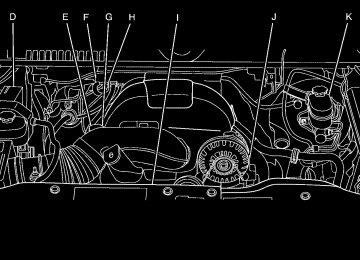
The vehicle may have a memory function which lets pedal settings be saved and recalled. See Memory Seat, Mirrors, and Pedals on page 1-8 for more information. Engine Coolant Heater The engine coolant heater can provide easier starting and better fuel economy during engine warm-up in cold weather conditions at or below 0°F (− 18°C). Vehicles with an engine heater should be plugged in at least four hours before starting. An internal thermostat in the plug-end of the cord may exist which will prevent engine coolant heater operation at temperatures above 0°F (−18°C). To Use the Engine Coolant Heater 1. Turn off the engine. 2. Open the hood and unwrap the electrical cord. The
cord is located on the driver’s side of the engine compartment, near the power steering fluid reservoir.
3. Plug the cord into a normal, grounded 110-volt AC
outlet.
{ CAUTION:
Plugging the cord into an ungrounded outlet could cause an electrical shock. Also, the wrong kind of extension cord could overheat and cause a fire. You could be seriously injured. Plug the cord into a properly grounded three-prong 110-volt AC outlet. If the cord will not reach, use a heavy-duty three-prong extension cord rated for at least 15 amps.
4. Before starting the engine, be sure to unplug and
store the cord as it was before to keep it away from moving engine parts. If you do not, it could be damaged.
The length of time the heater should remain plugged in depends on several factors. Ask a dealer/retailer in the area where you will be parking the vehicle for the best advice on this.
2-36
Active Fuel Management™ Vehicles with V8 engines may have Active Fuel Management™. This system allows the engine to operate on either all or half of its cylinders, depending on the driving conditions. When less power is required, such as cruising at a constant vehicle speed, the system will operate in the half cylinder mode, allowing the vehicle to achieve better fuel economy. When greater power demands are required, such as accelerating from a stop, passing, or merging onto a freeway, the system will maintain full-cylinder operation. If your vehicle has an Active Fuel Management™ indicator, see DIC Operation and Displays (With DIC Buttons) on page 3-46 or DIC Operation and Displays (Without DIC Buttons) on page 3-52 for more information on using this display.
Automatic Transmission Operation The vehicle has a Hydra-Matic® 6L80 automatic transmission, and has an electronic shift position indicator within the instrument panel cluster. The electronic shift position indicator displays when the shift lever is moved out of P (Park). There are several different positions for the shift lever.
See “Range Selection Mode” later in this section.
2-37
R (Reverse): Use this gear to back up. Notice: Shifting to R (Reverse) while the vehicle is moving forward could damage the transmission. The repairs would not be covered by the vehicle warranty. Shift to R (Reverse) only after the vehicle is stopped. To rock the vehicle back and forth to get out of snow, ice, or sand without damaging the transmission, see If Your Vehicle is Stuck in Sand, Mud, Ice, or Snow on page 4-32.
N (Neutral): In this position, the engine does not connect with the wheels. To restart the engine when the vehicle is already moving, use N (Neutral) only. Also, use N (Neutral) when the vehicle is being towed.
P (Park): This position locks your rear wheels. It is the best position to use when you start the engine because the vehicle cannot move easily.
When parked on a hill, especially when the vehicle has a heavy load, you may notice an increase in the effort to shift out of P (Park). See Torque Lock (Automatic Transmission) under Shifting Into Park on page 2-50 for more information.
{ CAUTION:
It is dangerous to get out of the vehicle if the shift lever is not fully in P (Park) with the parking brake firmly set. The vehicle can roll. Do not leave the vehicle when the engine is running unless you have to. If you have left the engine running, the vehicle can move suddenly. You or others could be injured. To be sure the vehicle will not move, even when you are on fairly level ground, always set the parking brake and move the shift lever to P (Park). See Shifting Into Park on page 2-50. If you are pulling a trailer, see Towing a Trailer on page 4-47.
2-38
{ CAUTION:
Shifting into a drive gear while the engine is running at high speed is dangerous. Unless your foot is firmly on the brake pedal, the vehicle could move very rapidly. You could lose control and hit people or objects. Do not shift into a drive gear while the engine is running at high speed.
Notice: Shifting out of P (Park) or N (Neutral) with the engine running at high speed may damage the transmission. The repairs would not be covered by the vehicle warranty. Be sure the engine is not running at high speed when shifting the vehicle.
D (Drive): This position is for normal driving. It provides the best fuel economy for the vehicle. If you need more power for passing, and you are: (cid:129) Going less than about 35 mph (55 km/h), push the
accelerator pedal about halfway down.
(cid:129) Going about 35 mph (55 km/h) or more, push the
accelerator all the way down.
D (Drive) can be used when towing a trailer, carrying a heavy load, driving on steep hills, or for off-road driving. You may want to shift the transmission to a lower gear selection if the transmission shifts too often. Downshifting the transmission in slippery road conditions could result in skidding, see “Skidding” under Loss of Control on page 4-11
When temperatures are very cold, the Hydra-Matic® Automatic Transmission’s gear shifting may be delayed providing more stable shifts until the engine warms up. Shifts may be more noticeable with a cold transmission. This difference in shifting is normal.M (Manual Mode): This position lets drivers select the range of gears appropriate for current driving conditions. See Range Selection Mode later in this section. Notice: Spinning the tires or holding the vehicle in one place on a hill using only the accelerator pedal may damage the transmission. The repair will not be covered by the vehicle warranty. If you are stuck, do not spin the tires. When stopping on a hill, use the brakes to hold the vehicle in place.
2-39
The vehicle has a shift stabilization feature that adjusts the transmission shifting to the current driving conditions in order to reduce rapid upshifts and downshifts. This shift stabilization feature is designed to determine, before making an upshift, if the engine will be able to maintain vehicle speed by analyzing things such as throttle position, vehicle load, and hill grade. If the shift stabilization feature determines that a current vehicle speed cannot be maintained, the transmission does not upshift and instead holds the current gear. In some cases, this may appear to be a delayed shift, however the transmission is operating normally. The vehicle’s transmission uses adaptive shift controls. Adaptive shift controls continually compares key shift parameters to pre-programmed ideal shift conditions stored in the transmissions computer. The transmission constantly makes adjustments to improve vehicle performance according to the way the vehicle is being used, such as with a heavy load. During this adaptive shift controls process, some shifts may feel different as the transmission determines the best settings for a particular shift.
2-40
Range Selection Mode
On vehicles with a Range Selection Mode, this feature may be used to control the vehicle’s transmission. To use this feature, do the following: 1. Move the shift lever to the M (Manual Mode). 2. Press the plus/minus button, to upshift or downshift
selecting the desired range of gears for current driving conditions.
When in M (Manual Mode) a number displays next to the M, indicating the current gear that has been selected. The number displayed in the gear indicator is the highest gear that can be used. However, the vehicle can automatically shift to lower gears as it adjusts to driving conditions. This means that all gears below that number are available. When 5 (Fifth) is selected, 1 (First) through 5 (Fifth) gears are automatically shifted by the vehicle, but 6 (Sixth) cannot be used until the plus/minus button located on the steering column lever is used to change to the gear. Range Selection Mode controls the vehicle and engine speed while driving down a hill or towing a trailer, by allowing you to select a desired range of gears. Grade Braking is not available when the Range Selection Mode is active. See Tow/Haul Mode on page 2-41 for more information. While using the Range Selection Mode, Cruise Control and the Tow/Haul mode can be used.
Tow/Haul Mode
The vehicle has a tow/haul mode. The tow/haul mode adjusts the transmission shift pattern to reduce shift cycling, providing increased performance, vehicle control, and transmission cooling while towing or hauling heavy loads. Press the button located on the end of the shift lever to turn the tow/haul on or off. While the tow/haul is on, a light on the instrument panel cluster comes on. See Tow/Haul Mode Light on page 3-44 for more information. Also see “Tow Haul Mode” under Towing a Trailer on page 4-47 for more information.
2-41
Cruise Grade Braking Cruise Grade Braking assists when driving on a downhill grade. It maintains vehicle speed by automatically implementing a shift schedule that uses the engine and the transmission to slow the vehicle. Cruise Grade Braking operates while Cruise Control is engaged in Tow/Haul mode to assist in maintaining vehicle speed under loaded vehicle conditions. It utilizes vehicle acceleration and deviation from desired speed to determine the correct gear for the operating condition. If vehicle speed is above the desired speed the transmission will downshift to slow the vehicle. If vehicle speed is near or below desired speed the trans will upshift, allowing vehicle speed to increase. While in the Range Select Mode (RSM) mode, cruise grade braking is not available. See Automatic Transmission Operation on page 2-37.
Grade Braking The Grade Braking shift modes can be activated by pressing the button on the end of the shift control lever. While in Range Selection Mode, Grade Braking is deactivated allowing the driver to select a desired range of gears. Grade Braking is only active while the Tow/Haul Mode is selected and you are not in the Range Selection Mode. See “Tow/Haul Mode listed previously and Automatic Transmission Operation on page 2-37 for more information on the Range Selection Mode. Grade Braking assists in maintaining desired vehicle speeds when driving on downhill grades by automatically implementing a shift schedule that utilizes the engine and transmission to slow the vehicle. This reduces wear on the braking system and increases control of the vehicle. Grade Braking monitors vehicle speed, acceleration, engine torque and brake pedal usage. Using this information, it detects when the truck is on a downhill grade and the driver desires to slow the vehicle by pressing the brake. Also see Towing a Trailer on page 4-47 for more information.
2-42
Four-Wheel Drive If the vehicle has four-wheel drive, you can send the engine’s driving power to all four wheels for extra traction. Read the following before using four-wheel drive. Notice: Driving on clean, dry pavement in Four-Wheel-Drive High or Four-Wheel-Drive Low for an extended period of time may cause premature wear on your vehicle’s powertrain. Do not drive on clean, dry pavement in Four-Wheel-Drive High or Four-Wheel-Drive Low for extended periods of time. While driving on clean dry pavement and during tight turns, you may experience a vibration in the steering system. The vehicle has StabiliTrak®. Shifting into Four-Wheel-Drive Low will turn Traction Control and StabiliTrak® off. See StabiliTrak® System on page 4-6. Front Axle The front axle engages and disengages automatically when you shift the transfer case. Some delay for the axle to engage or disengage is normal.
Automatic Transfer Case
The transfer case knob is located to the left of the instrument panel cluster.
Use this dial to shift into and out of four-wheel drive. You can choose among five driving settings: Indicator lights in the switches show you which setting you are in. The indicator lights will come on briefly when you turn on the ignition and the last chosen setting will stay on. If the lights do not come on, you should take the vehicle to your dealer/retailer for service. An indicator light will flash while shifting. It will stay on when the shift is completed. If for some reason the transfer case cannot make a requested shift, it will return to the last chosen setting.
2-43
2 m (Two-Wheel Drive High): This setting is used for driving in most street and highway situations. The front axle is not engaged in two-wheel drive. This setting also provides the best fuel economy.
AUTO (Automatic Four-Wheel Drive): This setting is ideal for use when road surface traction conditions are variable. When driving your vehicle in AUTO, the front axle is engaged, but the vehicle’s power is primarily sent to the rear wheels. When the vehicle’s software determines a need for more traction, the system will transfer more power to the front wheels. Driving in this mode results in slightly lower fuel economy than Two-Wheel Drive High. 4 m (Four-Wheel Drive High): Use the four-wheel high position when you need extra traction, such as on snowy or icy roads or in most off-road situations. This setting also engages your front axle to help drive the vehicle. This is the best setting to use when plowing snow. 4 n (Four-Wheel Drive Low): This setting also engages the front axle and delivers extra torque. You may never need this setting. It sends maximum power to all four wheels. You might choose Four-Wheel Drive Low if you are driving off-road in deep sand, deep mud, deep snow, and while climbing or descending steep hills.
The vehicle has StabiliTrak®. Shifting into Four-Wheel-Drive Low will turn Traction Control and StabiliTrak® off. See StabiliTrak® System on page 4-6.
{ CAUTION:
Shifting the transfer case to N (Neutral) can cause the vehicle to roll even if the transmission is in P (Park). You or someone else could be seriously injured. Be sure to set the parking brake before placing the transfer case in N (Neutral). See Parking Brake on page 2-48.
N (Neutral): Shift the vehicle’s transfer case to N (Neutral) only when towing the vehicle. See Recreational Vehicle Towing on page 4-40 or Towing Your Vehicle on page 4-40 for more information. If the SERVICE 4 WHEEL DRIVE message stays on, you should take the vehicle to your dealer/retailer for service. See “SERVICE 4 WHEEL DRIVE message” under DIC Warnings and Messages on page 3-58.
2-44
Shifting Into Four-Wheel Drive High or AUTO (Automatic Four-Wheel Drive) Turn the knob to the Four-Wheel High or AUTO position. This can be done at any speed, except when shifting from Four-Wheel Drive Low. The indicator light will flash while shifting. It will remain on when the shift is completed. Shifting Into Two-Wheel Drive High Turn the knob to the Two-Wheel High position. This can be done at any speed, except when shifting from Four-Wheel Drive Low. See shifting out of Four-Wheel Drive Low later in this section for more information. Shifting Into Four-Wheel Drive Low When Four-Wheel Low is engaged, vehicle speed should be kept below 45 mph (72 km/h). Extended high-speed operation in 4L may damage or shorten the life of the drivetrain. To shift to the Four-Wheel Drive Low position, the ignition must be in ON/RUN and the vehicle must be stopped or moving less than 3 mph (5 km/h) with the transmission in N (Neutral). The preferred method for shifting into Four-Wheel Drive Low is to have the vehicle moving 1 to 2 mph (1.6 to 3.2 km/h). Turn the knob to the Four-Wheel Drive Low position.
You must wait for the Four-Wheel Drive Low indicator light to stop flashing and remain on before shifting the transmission into gear. Notice: Shifting the transmission into gear before the Four-Wheel Drive Low indicator light has stopped flashing could damage the transfer case. To help avoid damaging the vehicle, always wait for the Four-Wheel Drive Low indicator light to stop flashing before shifting the transmission into gear. The vehicle may have significant engagement noise and bump when shifting between Four-Wheel Drive Low and Four-Wheel Drive High ranges or from N (Neutral) while the engine is running. If the knob is turned to the Four-Wheel Drive Low position when the vehicle is in gear and/or moving, the Four-Wheel Drive Low indicator light will flash for 30 seconds and not complete the shift unless the vehicle is moving less than 3 mph (5 km/h) and the transmission is in N (Neutral). After 30 seconds the transfer case will shift to Four-Wheel Drive High mode.
2-45
Shifting Out of Four-Wheel Drive Low To shift from Four-Wheel Drive Low to Four-Wheel Drive High, AUTO, or Two-Wheel Drive High, the vehicle must be stopped or moving less than 3 mph (5 km/h) with the transmission in N (Neutral) and the ignition in ON/RUN. The preferred method for shifting out of Four-Wheel Drive Low is to have your vehicle moving 1 to 2 mph (1.6 to 3.2 km/h). Turn the knob to the Four-Wheel Drive High, AUTO, or Two-Wheel Drive High position. You must wait for the Four-Wheel Drive High, AUTO, or Two-Wheel Drive High indicator light to stop flashing and remain on before shifting the transmission into gear. Notice: Shifting the transmission into gear before the Four-Wheel Drive Low indicator light has stopped flashing could damage the transfer case. To help avoid damaging the vehicle, always wait for the Four-Wheel Drive Low indicator light to stop flashing before shifting the transmission into gear. The vehicle may have significant engagement noise and bump when shifting between Four-Wheel Drive Low and Four-Wheel Drive High ranges or from N (Neutral) while the engine is running.
If the knob is turned to the Four-Wheel Drive High, AUTO, or Two-Wheel Drive High switch position when the vehicle is in gear and/or moving, the Four-Wheel Drive High, AUTO or Two-Wheel Drive High indicator light will flash for 30 seconds but will not complete the shift unless the vehicle is moving less than 3 mph (5 km/h) and the transmission is in N (Neutral). Shifting into Neutral To shift the transfer case to N (Neutral) do the following:
1. Make sure the vehicle is parked so that it will
not roll.
2. Set the parking brake and apply the regular brake pedal. See Parking Brake on page 2-48 for more information.
3. Start the vehicle or turn the ignition to ON/RUN. 4. Put the transmission in N (Neutral). 5. Shift the transfer case to Two-Wheel Drive High. 6. Turn the transfer case dial clockwise to N (Neutral)
until it stops and hold it there until the N (Neutral) light starts blinking. This will take at least 10 seconds. Then slowly release the dial to the Four-Wheel Drive Low position. The N (Neutral) light will come on when the transfer case shift to N (Neutral) is complete.
2-46
7. If the engine is running, verify that the transfer case
is in N (Neutral) by shifting the transmission to R (Reverse) for one second, then shift the transmission to D (Drive) for one second.
8. Turn the ignition to ACC/ACCESSORY, which will
turn the engine off.
9. Place the transmission shift lever in P (Park). 10. Release the parking brake prior to moving the
vehicle.
11. Turn the ignition to LOCK/OFF. Shifting Out of Neutral To shift out of N Neutral do the following: 1. Set the parking brake and apply the regular brake
pedal.
2. Turn the ignition to ON/RUN with the engine off,
and shift the transmission to N (Neutral).
3. Turn the transfer case dial to the desired transfer
case shift position (Two-Wheel Drive High, Four-Wheel Drive High, AUTO). After the transfer case has shifted out of N (Neutral), the N (Neutral) light will go out.
4. Release the parking brake prior to moving the
vehicle.
Notice: Shifting the transmission into gear before the Four-Wheel Drive Low indicator light has stopped flashing could damage the transfer case. To help avoid damaging the vehicle, always wait for the Four-Wheel Drive Low indicator light to stop flashing before shifting the transmission into gear. 5. Start the engine and shift the transmission to
the desired position.
Excessively shifting the transfer case into or out of the different modes may cause the transfer case to enter the shift protection mode. This will protect the transfer case from possible damage and will only allow the transfer case to respond to one shift per 10 seconds. The transfer case may stay in this mode for up to three minutes.
2-47
If the ignition is on, the brake system warning light will come on. See Brake System Warning Light on page 3-36. A chime sounds and the warning light flashes when the parking brake is applied and the vehicle is moving at least 5 mph (8 km/h). To release the parking brake, hold the regular brake pedal down. Then pull the bottom edge of the lever with the parking brake symbol, located above the parking brake pedal. If the ignition is on when the parking brake is released, the brake system warning light goes off. Notice: Driving with the parking brake on can overheat the brake system and cause premature wear or damage to brake system parts. Make sure that the parking brake is fully released and the brake warning light is off before driving. If you are towing a trailer and are parking on any hill, see Towing a Trailer on page 4-47.
Parking Brake
For vehicles with a release handle, set the parking brake by holding the regular brake pedal down, then pushing down the parking brake pedal.
2-48
For vehicles without a release handle, set the parking brake by holding the regular brake pedal down, then pushing down the parking brake pedal.
If the ignition is on, the brake system warning light will come on. See Brake System Warning Light on page 3-36. Notice: Driving with the parking brake on can overheat the brake system and cause premature wear or damage to brake system parts. Make sure that the parking brake is fully released and the brake warning light is off before driving. To release the parking brake, hold the regular brake pedal down, then push down momentarily on the parking brake pedal until you feel the pedal release. Slowly pull your foot up off the park brake pedal. If the parking brake is not released when you begin to drive, the brake system warning light will flash and a chime will sound warning you that the parking brake is still on. If you are towing a trailer and are parking on a hill, see Towing a Trailer on page 4-47.
2-49
2. Move the shift lever into the P (Park) position by
pulling the shift lever toward you and moving it up as far as it will go.
3. Be sure the transfer case is in a drive gear — not
in N (Neutral).
4. Turn the ignition key to LOCK/OFF. 5. Remove the key and take it with you. If you can
leave the vehicle with the ignition key in your hand, the vehicle is in P (Park).
Shifting Into Park
{ CAUTION:
It can be dangerous to get out of the vehicle if the shift lever is not fully in P (Park) with the parking brake firmly set. The vehicle can roll. If you have left the engine running, the vehicle can move suddenly. You or others could be injured. To be sure the vehicle will not move, even when you are on fairly level ground, use the steps that follow. With four-wheel drive, if the transfer case is in Neutral, the vehicle will be free to roll, even if the shift lever is in P (Park). So, be sure the transfer case is in a drive gear — not in Neutral. If you are pulling a trailer, see Towing a Trailer on page 4-47.
1. Hold the brake pedal down, then set the parking
brake. See Parking Brake on page 2-48 for more information.
2-50
Leaving the Vehicle With the Engine Running
{ CAUTION:
It can be dangerous to leave the vehicle with the engine running. The vehicle could move suddenly if the shift lever is not fully in P (Park) with the parking brake firmly set. If you have four-wheel drive and the transfer case is in Neutral, the vehicle will be free to roll, even if the shift lever is in P (Park). So be sure the transfer case is in a drive gear — not in Neutral. And, if you leave the vehicle with the engine running, it could overheat and even catch fire. You or others could be injured. Do not leave the vehicle with the engine running unless you have to.
If you have to leave the vehicle with the engine running, be sure your vehicle is in P (Park) and the parking brake is firmly set before you leave it. After you move the shift lever into P (Park), hold the regular brake pedal down. Then, see if you can move the shift lever away from P (Park) without first pulling it toward you. If you can, it means that the shift lever was not fully locked into P (Park). Torque Lock If you are parking on a hill and you do not shift your transmission into P (Park) properly, the weight of the vehicle may put too much force on the parking pawl in the transmission. You may find it difficult to pull the shift lever out of P (Park). This is called torque lock. To prevent torque lock, set the parking brake and then shift into P (Park) properly before you leave the driver seat. To find out how, see Shifting Into Park on page 2-50. When you are ready to drive, move the shift lever out of P (Park) before you release the parking brake. If torque lock does occur, you may need to have another vehicle push yours a little uphill to take some of the pressure from the parking pawl in the transmission, then you will be able to pull the shift lever out of P (Park).
2-51
Shifting Out of Park This vehicle is equipped with an electronic shift lock release system. The shift lock release is designed to: (cid:129) Prevent ignition key removal unless the shift
lever is in P (Park) with the shift lever button fully released, and
(cid:129) Prevent movement of the shift lever out of P (Park),
unless the ignition is in ON/RUN or ACC/ACCESSORY and the regular brake pedal is applied.
The shift lock release is always functional except in the case of an uncharged or low voltage (less than 9 volt) battery. If the vehicle has an uncharged battery or a battery with low voltage, try charging or jump starting the battery. See Jump Starting on page 5-40 for more information. To shift out of P (Park) use the following: 1. Apply the brake pedal. 2. Move the shift lever to the desired position.
If you still are unable to shift out of P (Park): 1. Ease the pressure on the shift lever. 2. While holding down the brake pedal, press the shift
lever all the way into P (Park).
3. Move the shift lever to the desired position. If you are still having a problem shifting, then have the vehicle serviced soon.
Parking Over Things That Burn
{ CAUTION:
Things that can burn could touch hot exhaust parts under the vehicle and ignite. Do not park over papers, leaves, dry grass, or other things that can burn.
2-52
Engine Exhaust
{ CAUTION:
Engine exhaust contains Carbon Monoxide (CO) which cannot be seen or smelled. Exposure to CO can cause unconsciousness and even death. Exhaust may enter the vehicle if:
(cid:129) The vehicle idles in areas with poor ventilation
(parking garages, tunnels, deep snow that may block underbody airflow or tail pipes). (cid:129) The exhaust smells or sounds strange or
(cid:129) The exhaust system leaks due to corrosion or
different.
damage.
CAUTION:
(Continued)
CAUTION:
(Continued)
(cid:129) The vehicle’s exhaust system has been
modified, damaged or improperly repaired. (cid:129) There are holes or openings in the vehicle
body from damage or after-market modifications that are not completely sealed. If unusual fumes are detected or if it is suspected that exhaust is coming into the vehicle:
(cid:129) Drive it only with the windows
completely down.
(cid:129) Have the vehicle repaired immediately.
Never park the vehicle with the engine running in an enclosed area such as a garage or a building that has no fresh air ventilation.
2-53
Running the Vehicle While Parked It is better not to park with the engine running. But if you ever have to, here are some things to know.
{ CAUTION:
Idling a vehicle in an enclosed area with poor ventilation is dangerous. Engine exhaust may enter the vehicle. Engine exhaust contains Carbon Monoxide (CO) which cannot be seen or smelled. It can cause unconsciousness and even death. Never run the engine in an enclosed area that has no fresh air ventilation. For more information, see Engine Exhaust on page 2-53.
{ CAUTION:
It can be dangerous to get out of the vehicle if the automatic transmission shift lever is not fully in P (Park) with the parking brake firmly set. The
CAUTION:
(Continued)
2-54
CAUTION:
(Continued)
vehicle can roll. Do not leave the vehicle when the engine is running unless you have to. If you have left the engine running, the vehicle can move suddenly. You or others could be injured. To be sure the vehicle will not move, even when you are on fairly level ground, always set the parking brake and move the shift lever to P (Park).
{ CAUTION:
Four-wheel drive vehicles with the transfer case in N (Neutral) will allow the vehicle to roll, even if the automatic transmission shift lever is in P (Park). So, be sure the transfer case is in a drive gear — not in N (Neutral). Always set the parking brake.
Follow the proper steps to be sure the vehicle will not move. See Shifting Into Park on page 2-50. If pulling a trailer, see Towing a Trailer on page 4-47.
Mirrors
Manual Rearview Mirror Hold the inside rearview mirror in the center to move it for a clearer view behind your vehicle. Adjust the mirror to avoid glare from the headlamps behind you. Push the tab forward for daytime use and pull it for nighttime use.
Automatic Dimming Rearview Mirror The vehicle may have an automatic dimming inside rearview mirror. Vehicles with OnStar® have three additional control buttons located at the bottom of the mirror. See your dealer/retailer for more information about OnStar® and how to subscribe to it. See OnStar® System on page 2-66 for more information about the services OnStar® provides.
O (On/Off): Press to turn the dimming feature on or off. The vehicle may also have a Rear Vision Camera (RVC). See Rear Vision Camera (RVC) on page 2-61
for more information. If the vehicle has RVC, the O (On/Off) button for turning the automatic dimming feature on or off will not be available. Automatic Dimming Mirror Operation Automatic dimming reduces the glare from the headlamps of the vehicle behind you. The dimming feature comes on and the indicator light illuminates each time the ignition is turned to start. Cleaning the Mirror Do not spray glass cleaner directly on the mirror. Use a soft towel dampened with water.2-55
Outside Power Mirrors
Outside Power Foldaway Mirrors
Vehicles with outside power mirrors have controls located on the driver door armrest.
Vehicles with outside power foldaway mirrors have controls located on the driver door armrest.
To adjust each mirror:
1. Press (A) or (B) to select the driver or passenger
side mirror.
2. Press one of the four arrows located on the control
pad to adjust the mirror.
3. Adjust each outside mirror to see a little of the
vehicle, and the area behind your vehicle.
4. Press either (A) or (B) again to deselect the mirror. Manually fold the mirrors inward to prevent damage when going through an automatic car wash. To fold, push the mirror toward the vehicle. Push the mirror outward, to return to its original position.
2-56
Mirror Adjustment 1. Press (C) to fold the mirrors out to the driving
position.
2. Press (D) to fold the mirrors in to the folded
position.
Resetting the Power Foldaway Mirrors Reset the power foldaway mirrors if:
The mirrors are accidentally obstructed while folding. They are accidentally manually folded/unfolded. The mirrors will not stay in the unfolded position. The mirrors vibrate at normal driving speeds.
To reset the power foldaway mirrors, fold and unfold them one time using the mirror controls. This will reset them to their normal position. Automatic Dimming The driver outside mirror adjusts for the glare of the headlamps behind you. See Automatic Dimming Rearview Mirror on page 2-55 for more information. Turn Signal Indicator The vehicle may also have a turn signal indicator on the mirror. An arrow on the mirror flashes in the direction of the turn or lane change.
Park Tilt Mirrors If the vehicle has the memory package, the passenger and/or driver mirror tilts to a preselected position when the vehicle is in R (Reverse). This feature lets the driver view the curb when parallel parking. The mirror(s) return to the original position when the vehicle is shifted out of R (Reverse), or the ignition is turned off or to OFF/LOCK. Turn this feature on or off through the Driver Information Center (DIC). See DIC Vehicle Customization (With DIC Buttons) on page 3-67 for more information.
Outside Convex Mirror
{ CAUTION:
A convex mirror can make things (like other vehicles) look farther away than they really are. If you cut too sharply into the right lane, you could hit a vehicle on the right. Check the inside mirror or glance over your shoulder before changing lanes.
The passenger side mirror is convex shaped. A convex mirror’s surface is curved so more can be seen from the driver seat.
2-57
(cid:129) (cid:129) (cid:129) (cid:129) { CAUTION:
The Ultrasonic Rear Parking Assist (URPA) system does not replace driver vision. It cannot detect:
(cid:129) objects that are below the bumper,
underneath the vehicle, or if they are too close or far from the vehicle children, pedestrians, bicyclists, or pets.
If you do not use proper care before and while backing; vehicle damage, injury, or death could occur. Even with URPA, always check behind the vehicle before backing up. While backing, be sure to look for objects and check the vehicle’s mirrors.
Outside Heated Mirrors < (Rear Window Defogger): Press to heat the mirrors. See “Rear Window Defogger” under Dual Automatic Climate Control System on page 3-23 for more information. Object Detection Systems
Ultrasonic Rear Parking Assist (URPA) For vehicles with the Ultrasonic Rear Parking Assist (URPA) system, it operates at speeds less than 5 mph (8 km/h), and assists the driver with parking and avoiding objects while in R (Reverse). The sensors on the rear bumper are used to detect the distance to an object up to 8 feet (2.5 m) behind the vehicle, and at least 10 inches (25.4 cm) off the ground.
2-58
(cid:129) The display is located above the rear window and can be seen by looking over your right shoulder.
URPA uses three color-coded lights to provide distance and system information. How the System Works URPA comes on automatically when the shift lever is moved into R (Reverse). The rear display briefly illuminates to indicate the system is working. URPA operates only at speeds less than 5 mph (8 km/h). If the vehicle is above this speed, the red light on the rear display will flash.
To be detected, objects must be at least 10 inches (25.4 cm) off the ground and below tailgate level. Objects must also be within 8 feet (2.5 m) from the rear bumper. This distance may be less during warmer or humid weather. A single beep will sound the first time an object is detected between 40 inches (1 m) and 8 feet (2.5 m) away. Beeping will occur continuously when the vehicle is at 23 inches (0.6 m) or closer to an object. The following describes what will occur with the URPA display as the vehicle gets closer to a detected object:
Description amber light
amber/amber lights
amber/amber/red lights and continuous beeping
for five seconds
amber/amber/red lights flashing and continuous beeping for five seconds
English
8 ft 40 in
23 in
Metric 2.5 m 1.0 m
0.6 m
1 ft
0.3 m
2-59
The system can be disabled by pressing the rear park aid disable button located next to the radio.
The indicator light will come on and PARK ASSIST OFF displays on the Driver Information Center (DIC) to indicate that URPA is off, see DIC Warnings and Messages on page 3-58 for information about clearing the message. Notice: lowered, it may not detect an object behind your vehicle, and you might back into the object and damage your vehicle. Always verify the tailgate is closed when using URPA or turn off URPA when driving with the tailgate lowered.
If you use URPA while the tailgate is
2-60
When the System Does Not Seem to Work Properly If the URPA system will not activate due to a temporary condition, the message PARK ASSIST OFF will be displayed on the DIC and a red light will be shown on the rear URPA display when the shift lever is moved into R (Reverse). This occurs under the following conditions:
The driver disables the system. The ultrasonic sensors are not clean. Keep the vehicle’s rear bumper free of mud, dirt, snow, ice and slush. For cleaning instructions, see Washing Your Vehicle on page 5-103.
(cid:129) A trailer was attached to the vehicle, or a bicycle or an object was hanging out of the tailgate during the last drive cycle, the red light may illuminate in the rear display. Once the attached object is removed, URPA will return to normal operation.
(cid:129) A tow bar is attached to the vehicle.
The vehicle’s bumper is damaged. Take the vehicle to your dealer/retailer to repair the system.
(cid:129) Other conditions may affect system performance,
such as vibrations from a jackhammer or the compression of air brakes on a very large truck.
If the system is still disabled, after driving forward at least 15 mph (25 km/h), take the vehicle to your dealer/retailer.
(cid:129) (cid:129) (cid:129) Rear Vision Camera (RVC) This vehicle may have a Rear Vision Camera system. Read this entire section before using it.
{ CAUTION:
The Rear Vision Camera (RVC) system does not replace driver vision. RVC does not:
(cid:129) Detect objects that are outside the camera’s
field of view, below the bumper, or underneath the vehicle.
(cid:129) Detect children, pedestrians, bicyclists, or pets.
Do not back the vehicle by only looking at the rear vision camera screen, or use the screen during longer, higher speed backing maneuvers or where there could be cross-traffic. Your judged distances using the screen will differ from actual distances. So if you do not use proper care before backing up, you could hit a vehicle, child, pedestrian, bicyclist, or pet, resulting in vehicle damage, injury, or death. Even though the vehicle has the RVC system, always check carefully before backing up by checking behind and around the vehicle.
Vehicles Without Navigation System The rear vision camera system is designed to help the driver when backing up by displaying a view of the area behind the vehicle. When the key is in the ON/RUN position and the driver shifts the vehicle into R (Reverse), the video image automatically appears on the inside rear view mirror. Once the driver shifts out of R (Reverse), the video image automatically disappears from the inside rear view mirror. Turning the Rear Vision Camera System Off or On To turn off the rear vision camera system, press and hold z, located on the inside rearview mirror, until the left indicator light turns off. The rear vision camera display is now disabled. To turn the rear vision camera system on again, press and hold z until the left indicator light illuminates. The rear vision camera system display is now enabled and the display will appear in the mirror normally.
2-61
Vehicles With Navigation System The rear vision camera system is designed to help the driver when backing up by displaying a view of the area behind the vehicle. When the driver shifts the vehicle into R (Reverse), the video image automatically appears on the navigation screen. Once the driver shifts out of R (Reverse), the navigation screen will go back to the last screen that had been displayed, after a delay. Turning the Rear Vision Camera System On or Off To turn the rear vision camera system on or off: 1. Shift into P (Park). 2. Press the MENU button to enter the configure menu options, then press the MENU hard key to select Display or touch the Display screen button. 3. Select the Rear Camera Options screen button. The
Rear Camera Options screen will display.
2-62
4. Select the Video screen button. When the Video
screen button is highlighted the RVC system is on.
The delay that is received after shifting out of R (Reverse) is approximately 10 seconds. The delay can be cancelled by performing one of the following: (cid:129) Pressing a hard key on the navigation system. (cid:129) Shifting in to P (Park). (cid:129) Reach a vehicle speed of 5 mph (8 km/h). There is a message on the rear vision camera screen that states “Check Surroundings for Safety”.
Adjusting the Brightness and Contrast of the Screen To adjust the brightness and contrast of the screen, press the MENU button while the rear vision camera image is on the display. Any adjustments made will only affect the rear vision camera screen.
] (Brightness): Touch the + (plus) or – (minus) screen buttons to increase or decrease the brightness of the screen.
_ (Contrast): Touch the + (plus) or – (minus) screen buttons to increase or decrease the contrast of the screen. Symbols The navigation system may have a feature that lets the driver view symbols on the navigation screen while using the rear vision camera. The Ultrasonic Rear Park Assist (URPA) system must not be disabled to use the caution symbols. If URPA has been disabled and the symbols have been turned on, the Rear Parking Assist Symbols Unavailable error message may display. See Ultrasonic Rear Parking Assist (URPA) on page 2-58.
The symbols appear when an object has been detected by the URPA system. The symbol may cover the object when viewing the navigation screen. To turn the symbols on or off: 1. Make sure that URPA has not been disabled. 2. Shift into P (Park). 3. Press the MENU hard key to enter the configure
menu options, then press the MENU hard key repeatedly until Display is selected or touch the Display screen button.
4. Select the Rear Camera Options screen button.
The Rear Camera Options screen will display. 5. Touch the Symbols screen button. The screen
button will be highlighted when on.
Rear Vision Camera Error Messages
Service Rear Vision Camera System: This message can display when the system is not receiving information it requires from other vehicle systems. If any other problem occurs or if a problem persists, see your dealer/retailer.
2-63
Rear Vision Camera Location
The image is provided by the camera located under the liftgate handle. The camera uses a special lens. The distance of the image that appears on the screen differs from the actual distance. The area displayed by the camera is limited. The camera does not display objects which are close to either corner of the bumper or under the bumper. The area displayed on the screen can vary according to vehicle orientation or road conditions. The following illustration shows the field of view that the camera provides.
2-64
When the System Does Not Seem To Work Properly The rear vision camera system might not work properly or display a clear image if:
The RVC is turned off. See “Turning the Rear Camera System On or Off” earlier in this section. It is dark. The sun or the beam of headlights is shining directly into the camera lens. Ice, snow, mud, or anything else builds up on the camera lens. Clean the lens, rinse it with water, and wipe it with a soft cloth. The back of the vehicle is in an accident, the position and mounting angle of the camera can change or the camera can be affected. Be sure to have the camera and its position and mounting angle checked at your dealer/retailer. There are extreme temperature changes.
The rear vision camera system display in the rearview mirror may turn off or not appear as expected due to one of the following conditions. If this occurs the left indicator light on the mirror will flash. (cid:129) A slow flash may indicate a loss of video signal, or
no video signal present during the reverse cycle.
(cid:129) A fast flash may indicate that the display has been
on for the maximum allowable time during a reverse cycle, or the display has reached an Over Temperature limit. The fast flash conditions are used to protect the video device from high temperature conditions. Once conditions return to normal the device will reset and the green indicator will stop flashing.
During any of these fault conditions, the display will be blank and the indicator will continue to flash as long as the vehicle is in R (Reverse) or until the conditions return to normal. Pressing and holding z when the left indicator light is flashing will turn off the video display along with the left indicator light.
2-65
(cid:129) (cid:129) (cid:129) (cid:129) (cid:129) (cid:129) OnStar service is provided subject to the OnStar Terms and Conditions included in the OnStar Subscriber glove box literature. Some services such as Remote Door Unlock or Stolen Vehicle Location Assistance may not be available until the owner of the vehicle registers with OnStar. After the first prepaid year, contact OnStar to select a monthly or annual subscription payment plan. If a payment plan is not selected, the OnStar system and all services, including airbag notification and emergency services, may be deactivated and no longer available. For more information visit onstar.com (U.S.) or onstar.ca (Canada), or press the OnStar button to speak with an advisor. Not all OnStar services are available on all vehicles. To check if this vehicle is able to provide the services described below, or for a full description of OnStar services and system limitations, see the OnStar Owner’s Guide in the glove box or visit onstar.com (U.S.) or onstar.ca (Canada), contact OnStar at 1-888-4-ONSTAR (1-888-466-7827) or TTY 1-877-248-2080, or press the OnStar button to speak with an OnStar advisor 24 hours a day, 7 days a week.
OnStar® System
OnStar uses several innovative technologies and live advisors to provide a wide range of safety, security, information, and convenience services. If the airbags deploy, the system is designed to make an automatic call to OnStar Emergency advisors who can request emergency services be sent to your location. If the keys are locked in the vehicle, call OnStar at 1-888-4-ONSTAR to have a signal sent to unlock the doors. OnStar Hands-Free Calling, including 30 trial minutes good for 60 days, is available on most vehicles. OnStar Turn-by-Turn Navigation service, with one trial route, is available on most vehicles. Press the OnStar button to have an OnStar advisor contact Roadside Service.
2-66
OnStar Services Available with the Safe & Sound Plan (cid:129) Automatic Notification of Airbag Deployment (cid:129) Advanced Automatic Crash Notification (AACN)
(If equipped) Link to Emergency Services
(cid:129) Roadside Assistance (cid:129) Stolen Vehicle Location Assistance (cid:129) Remote Door Unlock/Vehicle Alert (cid:129) OnStar Vehicle Diagnostic Email (cid:129) GM Goodwrench On Demand Diagnostics (cid:129) OnStar Hands-Free Calling with 30 trial minutes (cid:129) OnStar Virtual Advisor (U.S. Only) OnStar Services Included with Directions & Connections Plan (cid:129) All Safe and Sound Plan Services (cid:129) OnStar Turn-by-Turn Navigation (If equipped) or
Driving Directions - Advisor delivered
(cid:129) RideAssist
Information and Convenience Services
OnStar Hands-Free Calling OnStar Hands-Free Calling allows eligible OnStar subscribers to make and receive calls using voice commands. Hands-Free Calling is fully integrated into the vehicle, and can be used with OnStar Pre-Paid Minute Packages. Most vehicles include 30 trial minutes good for 60 days. Hands-Free Calling can also be linked to a Verizon Wireless service plan in the U.S. or a Bell Mobility service plan in Canada, depending on eligibility. To find out more, refer to the OnStar Owner’s Guide in the vehicle’s glove box, visit onstar.com or onstar.ca, or speak with an OnStar advisor by pressing the OnStar button or calling 1-888-4-ONSTAR (1-888-466-7827). OnStar Turn-by-Turn Navigation Vehicles with the OnStar Turn-by-Turn Navigation system can provide voice-guided driving directions. Press the OnStar button to have an OnStar advisor locate a business or address and download driving directions to the vehicle. Voice-guided directions to the desired destination will play through the audio system speakers. See the OnStar Owner’s Guide for more information.
2-67
(cid:129) (cid:129) OnStar Virtual Advisor OnStar Virtual Advisor is a feature of OnStar Hands-Free Calling that uses minutes to access location-based weather, local traffic reports, and stock quotes. Press the phone button and give a few simple voice commands to browse through the various topics. See the OnStar Owner’s Guide for more information. This feature is only available in the continental U.S. OnStar Steering Wheel Controls This vehicle may have a Talk/Mute button that can be used to interact with OnStar Hands-Free Calling. See Audio Steering Wheel Controls on page 3-130 for more information. On some vehicles, the mute button can be used to dial numbers into voice mail systems, or to dial phone extensions. See the OnStar Owner’s Guide for more information.
How OnStar Service Works The OnStar system can record and transmit vehicle information. This information is automatically sent to an OnStar Call Center when the OnStar button is pressed, the emergency button is pressed, or if the airbags or AACN system deploy. This information usually includes the vehicle’s GPS location and, in the event of a crash, additional information regarding the crash that the vehicle was involved in (e.g. the direction from which the vehicle was hit). When the Virtual Advisor feature of OnStar Hands-Free Calling is used, the vehicle also sends OnStar the vehicle’s GPS location so they can provide services where it is located. OnStar service cannot work unless the vehicle is in a place where OnStar has an agreement with a wireless service provider for service in that area. OnStar service also cannot work unless the vehicle is in a place where the wireless service provider OnStar has hired for that area has coverage, network capacity and reception when the service is needed, and technology that is compatible with the OnStar service. Not all services are available everywhere, particularly in remote or enclosed areas, or at all times. Location information about the vehicle is only available if the GPS satellite signals are unobstructed and available.
2-68
The vehicle must have a working electrical system, including adequate battery power, for the OnStar equipment to operate. There are other problems OnStar cannot control that may prevent OnStar from providing OnStar service at any particular time or place. Some examples are damage to important parts of the vehicle in a crash, hills, tall buildings, tunnels, weather or wireless phone network congestion. Your Responsibility Increase the volume of the radio if the OnStar advisor cannot be heard. If the light next to the OnStar buttons is red, the system may not be functioning properly. Press the OnStar button and request a vehicle diagnostic. If the light appears clear (no light is appearing), your OnStar subscription has expired and all services have been deactivated. Press the OnStar button to confirm that the OnStar equipment is active.
Universal Home Remote System The Universal Home Remote System provides a way to replace up to three hand-held Radio-Frequency (RF) transmitters used to activate devices such as garage door openers, security systems, and home lighting. This device complies with Part 15 of the FCC Rules. Operation is subject to the following two conditions: 1. This device may not cause harmful interference. 2. This device must accept any interference received,
including interference that may cause undesired operation.
This device complies with RSS-210 of Industry Canada. Operation is subject to the following two conditions: 1. This device may not cause interference. 2. This device must accept any interference received,
including interference that may cause undesired operation of the device.
Changes or modifications to this system by other than an authorized service facility could void authorization to use this equipment.
2-69
Universal Home Remote System Operation (With Three Round LED)
This vehicle may have the Universal Home Remote System. If there are three round Light Emitting Diode (LED) indicator lights above the Universal Home Remote buttons, follow the instructions below. This system provides a way to replace up to three remote control transmitters used to activate devices such as garage door openers, security systems, and home automation devices.
Do not use this system with any garage door opener that does not have the stop and reverse feature. This includes any garage door opener model manufactured before April 1, 1982. Read the instructions completely before attempting to program the transmitter. Because of the steps involved, it may be helpful to have another person assist with programming the transmitter. Be sure to keep the original remote control transmitter for use in other vehicles, as well as, for future programming. Only the original remote control transmitter is needed for Fixed Code programming. The programmed buttons should be erased when the vehicle is sold or the lease ends. See “Erasing Universal Home Remote Buttons” later in this section. Park the vehicle outside of the garage when programming a garage door. Be sure that people and objects are clear of the garage door or gate that is being programmed.
2-70
Programming Universal Home Remote — Rolling Code For questions or help programming the Universal Home Remote System, call 1-866-572-2728 or go to learcar2u.com. Most garage door openers sold after 1996 are Rolling Code units. Programming a garage door opener involves time-sensitive actions, so read the entire procedure before starting. Otherwise, the device will time out and the procedure will have to be repeated. To program up to three devices:
1. From inside the vehicle, press the two outside
buttons at the same time for one to two seconds, and immediately release them.
2. Locate in the garage, the garage door opener receiver (motor-head unit). Locate the “Learn” or “Smart” button. It can usually be found where the hanging antenna wire is attached to the motor-head unit and may be a colored button. Press this button. After pressing this button, complete the following steps in less than 30 seconds.
3. Immediately return to the vehicle. Press and hold
the Universal Home Remote button that will be used to control the garage door until the garage door moves. The indicator light, above the selected button, should slowly blink. This button may need to be held for up to 20 seconds.
2-71
4. Immediately, within one second, release the button
when the garage door moves. The indicator light will blink rapidly until programming is complete. 5. Press and release the same button again. The
garage door should move, confirming that programming is successful and complete.
To program up to three devices:
To program another Rolling Code device such as an additional garage door opener, a security device, or home automation device, repeat Steps 1 through 5, choosing a different function button in Step 3 than what was used for the garage door opener. If these instructions do not work, the garage door opener is probably a Fixed Code unit. Follow the Programming instructions that follow for a Fixed Code garage door opener. Programming Universal Home Remote — Fixed Code For questions or help programming the Universal Home Remote System, call 1-866-572-2728 or go to learcar2u.com. Most garage door openers sold before 1996 are Fixed Code units. Programming a garage door opener involves time-sensitive actions, so read the entire procedure before starting. Otherwise, the device will time out and the procedure will have to be repeated.
2-72
1. To verify that the garage door opener is a Fixed Code unit, remove the battery cover on the hand held transmitter supplied by the manufacturer of the garage door opener motor. If there are a row of dip switches similar to the graphic above, the garage door opener is a Fixed Code unit. If you do not see a row of dip switches, return to the previous section for Programming Universal Home Remote – Rolling Code. Your hand held transmitter can have between eight to 12 dip switches depending on the brand of transmitter.
The garage door opener receiver (motor head unit) could also have a row of dip switches that can be used when programming the Universal Home Remote. If the total number of switches on the motor head and hand held transmitter are different, or if the dip switch settings are different, use the dip switch settings on the motor head unit to program the Universal Home Remote. The motor head dip switch settings can also be used when the original hand held transmitter is not available.
Example of Eight Dip Switches with Two Positions
Example of Eight Dip Switches with Three Positions
The panel of switches might not appear exactly as they do in the examples above, but they should be similar. The switch positions on the hand-held transmitter could be labeled, as follows: (cid:129) A switch in the up position could be labeled as
“Up,” “+,” or “On.”
(cid:129) A switch in the down position could be labeled
as “Down,” “−,” or “Off.”
(cid:129) A switch in the middle position could be labeled
as “Middle,” “0,” or “Neutral.”
2-73
2. Write down the eight to 12 switch settings from left
to right as follows: (cid:129) When a switch is in the up position, write “Left.” (cid:129) When a switch is in the down position, write
“Right.” If a switch is set between the up and down position, write “Middle.” The switch settings written down in Step 2 now become the button strokes to be entered into the Universal Home Remote in Step 4. Be sure to enter the switch settings written down in Step 2, in order from left to right, into the Universal Home Remote, when completing Step 4.
3. From inside your vehicle, first firmly press all
three buttons at the same time for about three seconds. Release the buttons to put the Universal Home Remote into programming mode.
2-74
4. The indicator lights will blink slowly. Enter each
switch setting from Step 2 into your vehicle’s Universal Home Remote. You will have two and one-half minutes to complete Step 4. Now press one button on the Universal Home Remote for each switch setting as follows:
If you wrote “Left,” press the left button in the vehicle. If you wrote “Right,” press the right button in the vehicle. If you wrote “Middle,” press the middle button in the vehicle.
(cid:129) (cid:129) (cid:129) (cid:129) 5. After entering all of the switch positions, again, firmly press and release all three buttons at the same time. The indicator lights will turn on.
6. Press and hold the button that will be used to control the garage door until the garage door moves. The indicator light above the selected button should slowly blink. This button may need to be held for up to 55 seconds.
7. Immediately release the button when the garage door moves. The indicator light will blink rapidly until programming is complete.
8. Press and release the same button again. The
garage door should move, confirming that programming is successful and complete.
To program another Fixed Code device such as an additional garage door opener, a security device, or home automation device, repeat Steps 1-8, choosing a different button in Step 6 than what was used for the garage door opener. Using Universal Home Remote Press and hold the appropriate button for at least half of a second. The indicator light will come on while the signal is being transmitted.
Reprogramming Universal Home Remote Buttons Any of the three buttons can be reprogrammed by repeating the instructions. Erasing Universal Home Remote Buttons The programmed buttons should be erased when the vehicle is sold or the lease ends. To erase either Rolling Code or Fixed Code on the Universal Home Remote device: 1. Press and hold the two outside buttons at the same
time for approximately 20 seconds, until the indicator lights, located directly above the buttons, begin to blink rapidly.
2. Once the indicator lights begin to blink, release both
buttons. The codes from all buttons will be erased. For help or information on the Universal Home Remote System, call the customer assistance phone number under Customer Assistance Offices on page 7-6.
2-75
Storage Areas
Glove Box Lift up on the glove box lever to open it.
Cupholders For vehicles with cupholders for front and rear passengers, the cupholders are located in the center console and on the back of the center console. Press down on the access door and release to open and use the front cupholders. Pull down on the door located on the back of the console to use the rear cupholders. Push the door back down to close it. Push down and then back on the front cupholder to remove it for cleaning. For vehicles with a rear armrest/cuholder, it can be used by the reat seat passengers. Pull up and then out on the tab, located at the top center of the armrest. Then pull the armrest down to access the cupholder.
Center Overhead Console For vehicles with an overhead console, it contains reading lights and a small storage area. Press the button next to each light to turn it on and off.
Front Armrest Storage Area Vehicles with a center armrest storage compartment, located in the front bench seat, fold down the armrest and press the handle at the front of the armrest to open it. Let the cover pop up and swing open.
Center Console Storage For vehicles with a console compartment, cupholders are located between the bucket seats. Press the button and lift the console cover to open. The back of the console has a cupholder that folds down for the rear seat passenger to use.
2-76
Luggage Carrier Notice: Loading cargo on the luggage carrier that weighs more than 200 lbs (91 kg) or hangs over the rear or sides of the vehicle can damage the vehicle. Load cargo so that it rests on the slats as far forward as possible and against the side rails, making sure to fasten it securely. For vehicles with a luggage carrier, items can be loaded on top of the vehicle. The luggage carrier has siderails attached to the roof. It can also have crossrails which can be moved back and forth to help secure cargo. Tie the load to the siderails or siderail supports. Do not exceed the maximum vehicle capacity when loading the vehicle. For more information on vehicle capacity and loading, see Loading the Vehicle on page 4-34. Make sure the cargo is properly loaded. To prevent damage or loss of cargo while driving, periodically stop and check to make sure cargo is still securely fastened.
If small heavy objects are placed on the roof, cut a piece of 3/8 inch plywood to fit inside the crossrails and siderails to spread the load. Tie the plywood to the siderail supports.
Tie the load and secure it to the crossrails or the siderail supports. Use the crossrails only to keep the load from sliding. To move a crossrail, lift the release lever up, on both sides of the rail. Then slide the crossrail to the desired position balancing the force side to side. Press the release lever down on both sides of the rail, down to tighten it. Try to slide the crossrail back and forth slightly to make sure it is tight. To carry long items, move the crossrails as far apart as possible. Tie the load to the crossrails and the siderails or siderail supports. Also tie the load to the bumpers, but do not tie the load so tightly that the crossrails or siderails are damaged.
(cid:129) After moving a crossrail, be sure it is securely
locked into the siderail.
A Center High-Mounted Stoplamp (CHMSL) is located above the rear window glass. Make sure items loaded on the roof of the vehicle do not block or damage the CHMSL.
2-77
(cid:129) (cid:129) (cid:129) Cargo Cover Panels For vehicles with a three-piece cargo cover system, the cargo panels can be removed and stored in the cargo area of the vehicle.
To remove a cargo panel(s): 1. Lower the tailgate. See Tailgate on page 2-23 for
more information on the tailgate.
{ CAUTION:
Improperly stored cargo cover panels could be thrown about the vehicle during a collision or sudden maneuver. Someone could be injured. If a panel is removed, always store it in the proper storage location. When putting it back, always make sure that it is securely reattached.
Notice: Exceeding the weight limit of 250 lbs (113 kg) can damage the cargo covers, and the repairs would not be covered by the vehicle warranty. Do not put anything on top of the cargo covers over the weight limit.
2-78
The panels are embossed on the upper center portion with the numbers 1, 2 and 3. There are also numbered labels on the bottom of the panels. The numbers on the top and bottom of the panels will be used as reference when removing, storing and reinstalling the panels.
3. Remove cargo panel 2 in the same way and set it aside. Remove as many cargo panels as needed.
4. To remove cargo panel 1, unlock the two rear latches, lift the cover slightly and pull rearward.
After each cargo panel has been removed, store them within the cargo storage area using the cargo panel storage system.
2. Unlock the cargo panel 3 by pulling forward on the driver side and passenger side cargo panel latches, located on the bottom of each cargo panel.
2-79
Cargo Panel Storage System The three cargo panels can be stored in the cargo area using the storage strap system. Always use the storage strap system to store the cargo panels while driving.
To store the panels:
1. Secure the storage strap system in the cargo storage area by attaching the six clips included on the cargo strap system to the tie down locations on either side of the storage area.
Before storing the cargo panels, make sure that the latches on the cargo panels are in the locked position. The latches are locked when they are parallel to the front and back edge of the panel.
2-80
Use the following instructions for the proper storage sequence and location for each panel:
A. Secure clip A on the storage strap. B. Secure clip B on the storage strap. C. Place the remaining primary straps on top of the lid and tray at the top of the cargo area.
2. Starting with cargo panel 1, load the cargo panel with the latches facing up toward the side of the cargo box. Do the same for cargo panel 2 then panel 3. Make sure to store panel 2 with the latches facing down and panel 3 with latches facing up toward the side of the cargo box.
2-81
3. Place the primary straps over the three cargo
covers (A). Fasten the four strap clips (B).
4. Tighten all straps by pulling on the free end of each
strap.
2-82
5. Close both cross locks at the center of the strap
system to tightly secure.
Panels 3, 2, 1 Loaded
2-83
Reinstalling the Cargo Cover Panels The strap system can remain attached to the side of the cargo area while it is not in use, or it can be stored inside the top box storage compartment. See Top-Box Storage on page 2-92 for more information. To reinstall a cargo panel:
Driver Side Shown, Passenger Side Similar
Place the cover on the cargo box within 4 inches of the Midgate® and lower the rear of the panel within 2 to 3 inches from the top of the cargo box. Push the cover forward making sure that the guide block engages the retainer bracket opening. Continue to push forward until the panel is fully seated against the Midgate. Then lower the rear of the cover to engage the striker pegs (A) to align with the striker assembly (B).
1. Starting with cargo panel 1, place the latches in the unlocked position. Place cargo panel 1 on the cargo area rails while holding the back of the cargo panel up.
2-84
2. The driver side cargo cover panel latch must lock in
place before the passenger side latch can be locked. If this procedure is not followed exactly, the cargo cover panels might not correctly lock in place. Push the driver side latch toward the front of the vehicle to lock the cover in position. A click sounds when each latch locks. Lock the remaining passenger side latch on panel 1.
3. Install cargo cover 2 followed by 3 next. Place the latches in the unlocked position. Place the cargo cover panel on the cargo area rails while holding the back of the cargo panel up.
Driver Side Shown, Passenger Side Similar
Push the panel forward until it is snug against the other panel and then let the back of the panel down making sure that the pegs (A) align with the receivers (B).
4. Push the latches toward the front of the vehicle,
starting with the driver side latch, to lock the panel in place. A click sounds when each latch locks correctly.
2-85
Folding and Storage of Straps Fold the straps for storing inside the top box storage compartment:
1. Extend the six strap ends on a flat surface.
2. Fold the four primary strap ends toward the center
as shown.
2-86
3. Take the short strap and wrap it around the folded
webbing, forming a package.
4. Take the storage strap and wrap it around the
package. Finally, attach the hooks to the webbing and place the straps inside the top box storage compartment.
Cargo Tie Downs The vehicle has cargo tie downs, located in the rear cargo area. These can be used to secure cargo. The tie downs can also be used to secure the cargo cover panel strap system, if the vehicle has one. For more information see “Cargo Cover Panels” earlier in this section.
All-Weather Cargo Area The vehicle’s cargo area can be used in many different configurations--cargo panels on or off, Midgate® up or down, rear glass in or out. It has features that resist the elements and protect cargo. It is designed to quickly direct water out of the cargo box. The top drain grates, side rail channels, catch cups, Midgate® drain, cargo area floor drains and the rubber cargo mat help do this.
2-87
Even when all of these things are working properly and the cover system is on, there may be some instances (heavy rains, automated car washes, etc.) when water can collect the following areas:
F. Rear drains G. Cargo floor H. Cargo mat Maintenance and Cleaning To ensure that the water management system performs properly, be sure that the Midgate®, tailgate and cover system are fully closed and that all parts are clean and not blocked with debris. Follow the instructions given next in this section for the proper procedures on cleaning each item.
A. Top drain grates B. Removable front drain grate (Midgate® drain gate) C. Side rail channels and catch cups D. Front drains E. Water drainage area around both sides of the box
and the tailgate side
2-88
Top Drain Grates – Removal and Cleaning
To remove each drain grate, do the following: 1. Remove the cargo panels. See Cargo Cover Panels
on page 2-78 for more information.
The top drain grates are located near the rear window on both sides of the vehicle. Clean the grates and drains if there is a blockage.
2. Grasp the edges of the grate and pull it out from
the vehicle. Flush the drain with clean water.
2-89
To replace the drain grate:
Side Rail Channels
1. Line up the clips on the vehicle with the slots in the
grate and firmly push the grate down.
Do not force the grate. If it does not clip into place, realign the clips with the holes and try again.
The side rail channels are located on top of both sides of the cargo area. Flush them out with clean water if debris collects inside of them. Carefully load cargo into the cargo area, so that the rails do not get damaged.
2-90
Midgate® Drain Grate Removal and Cleaning
After hauling dirt, wood chips, pebbles etc. the Midgate drain should be flushed with water. First remove the drain grate: 1. Lower the Midgate®. See Midgate® on page 2-13
for more information.
The removable Midgate drain grate is located near the base of the Midgate.
2. Pull up on the rear side of the drain grate, tilt it
toward the front of the vehicle, and pull it out. Reverse the procedure to reinstall the drain grate.
2-91
Cargo Area Floor Drains
Top-Box Storage
The cargo net has cut outs for the four cargo-area floor drains located under the cargo mat near the sides of the cargo area. Periodically flush the drains through the cut outs to clear debris and allow water to drain from the cargo area. If the cargo area is extremely dirty lift up the edges of the cargo floor mat or take the whole mat out and flush the drains with water.
The vehicle has top-box storage units on both sides of the vehicle. The passenger side top box contains the tools needed to change a flat tire. Use the key to unlock or lock it. Press the key cylinder button and swing the lid open. Turn on the cargo lamps, if the vehicle has them, to light the inside of the cargo area. See Exterior Cargo Lamps on page 3-17
for more information.2-92
Sunroof Your vehicle may be equipped with a power sliding sunroof. To open or close the sunroof, the ignition needs to be turned to ON/RUN, or Retained Accessory Power (RAP) must be active. When RAP is active, the sunroof will work for 10 minutes after the ignition is turned off, or until a front door is opened. See Retained Accessory Power (RAP) on page 2-34 for more information.
There are two switches in the overhead console that operate the sunroof.
Manual-Open/Manual-Close: To open the sunroof press and hold the rear of the driver’s side switch until the sunroof reaches the desired position. To close the sunroof, press and hold the front of the driver’s side switch until the sunroof reaches the desired position. The sunshade will open automatically with the sunroof, but can also be opened manually.
The sunroof has a comfort stop feature which stops the sunroof from opening to the full-open position. From the comfort stop position, press the rear of the driver’s side switch a second time to open the sunroof to the full-open position.
When the sunroof is opened, an air deflector will automatically raise. The air deflector will retract when the sunroof is closed.
2-93
Anti-Pinch Feature: If an object is in the path of the sunroof while it is closing, the anti-pinch feature will detect the object and stop the sunroof from closing at the point of the obstruction. The sunroof will then open halfway, and the air deflector will raise. To close the sunroof once it has re-opened, refer to the “Express-Close” or “Manual-Close” functions described previously. If the sunroof is in the vent position, and there is an object in the path of the sunroof when it closing, the anti-pinch feature will detect the object and stop the sunroof. To close the sunroof once it has re-opened, refer to the “Manual-Close” or “Express-Close” functions described previously. Do not keep the sunroof open for long periods of time while the vehicle is not in use. Debris can collect in the tracks, damage the sunroof operation and plug the water draining system.
Express-Open/Express-Close: To express-open the sunroof, fully press and release the rear of the driver’s side switch. The sunroof will open automatically. To stop the sunroof partway, press the switch a second time. To express-close the sunroof, fully press and release the front of the driver’s side switch. The sunroof will close automatically. To stop the sunroof partway, press the switch a second time. The sunshade will open automatically with the sunroof, but can also be opened manually.
The sunroof has a comfort stop feature which stops the sunroof from opening to the full-open position. From the comfort stop position, press the rear of the driver’s side switch a second time to open the sunroof to the full-open position.
When the sunroof is opened, an air deflector will automatically raise. The air deflector will retract when the sunroof is closed.
Vent: The sunroof has an express-vent open feature. From the closed position, press the rear of the passenger’s side switch to vent the sunroof. To stop the sunroof partway, press the switch a second time. To close the sunroof, press and hold the front of the passenger’s side switch. To stop the sunroof partway, release the switch.
2-94
Section 3
Instrument Panel
Instrument Panel Overview ...............................3-4
Hazard Warning Flashers ................................3-6
Horn .............................................................3-6
Tilt Wheel .....................................................3-6
Turn Signal/Multifunction Lever .........................3-7
Turn and Lane-Change Signals ........................3-7
Headlamp High/Low-Beam Changer ..................3-8
Flash-to-Pass .................................................3-8
Windshield Wipers ..........................................3-9
Rainsense™ II Wipers .....................................3-9
Windshield Washer .......................................3-10
Cruise Control ..............................................3-11
Exterior Lamps .............................................3-14
Headlamps on Reminder ................................3-15
Daytime Running Lamps (DRL) .......................3-15
Automatic Headlamp System ..........................3-16
Fog Lamps ..................................................3-16
Exterior Cargo Lamps ....................................3-17
Instrument Panel Brightness ...........................3-17
Dome Lamps ...............................................3-17
Dome Lamp Override ....................................3-18
Entry/Exit Lighting .........................................3-18
Reading Lamps ............................................3-18
Electric Power Management ...........................3-18
Battery Run-Down Protection ..........................3-19
Accessory Power Outlet(s) .............................3-19
Ashtray(s) and Cigarette Lighter ......................3-20Climate Controls ............................................3-20
Climate Control System .................................3-20
Dual Automatic Climate Control System ...........3-23
Outlet Adjustment .........................................3-29
Warning Lights, Gages, and Indicators ............3-29
Instrument Panel Cluster ................................3-30
Speedometer and Odometer ...........................3-31
Trip Odometer ..............................................3-31
Tachometer .................................................3-31
Safety Belt Reminders ...................................3-31
Airbag Readiness Light ..................................3-32
Passenger Airbag Status Indicator ...................3-33
Charging System Light ..................................3-34
Voltmeter Gage ............................................3-35
Brake System Warning Light ..........................3-36
Antilock Brake System (ABS) Warning Light .....3-37
StabiliTrak® Indicator Light .............................3-37
Engine Coolant Temperature Gage ..................3-38
Tire Pressure Light .......................................3-38
Malfunction Indicator Lamp .............................3-39
Oil Pressure Gage ........................................3-41
Oil Pressure Light .........................................3-42
Security Light ...............................................3-43
Fog Lamp Light ............................................3-43
Cruise Control Light ......................................3-43
Highbeam On Light .......................................3-44
Tow/Haul Mode Light ....................................3-44
3-1Section 3
Instrument Panel
Fuel Gage ...................................................3-44
Low Fuel Warning Light .................................3-45
Driver Information Center (DIC) .......................3-46DIC Operation and Displays
(With DIC Buttons) ....................................3-46
DIC Operation and Displays
(Without DIC Buttons) ................................3-52
DIC Compass ..............................................3-55
DIC Warnings and Messages .........................3-58
DIC Vehicle Customization