- Download PDF Manual
-
{CAUTION:
Operating the engine with the air cleaner/filter off can cause you or others to be burned. The air cleaner not only cleans the air, it helps to stop flame if the engine backfires. If it is not there and the engine backfires, you could be burned. Do not drive with it off, and be careful working on the engine with the air cleaner/filter off.
5-24
If the air cleaner/filter is off, a backfire
Notice: can cause a damaging engine fire. And, dirt can easily get into your engine, which will damage it. Always have the air cleaner/filter in place when you are driving.
Automatic Transmission Fluid When to Check and Change A good time to check your automatic transmission fluid level is when the engine oil is changed. Change both the fluid and filter every 50,000 miles (83 000 km) if the vehicle is mainly driven under one or more of these conditions:
In heavy city traffic where the outside temperature regularly reaches 90°F (32°C) or higher. In hilly or mountainous terrain.
(cid:127) When doing frequent trailer towing. (cid:127) Uses such as found in taxi, police or delivery
service.
If you do not use your vehicle under any of these conditions, change the fluid and filter every 100,000 miles (166 000 km).
(cid:127) (cid:127) How to Check Because this operation can be a little difficult, you may choose to have this done at the dealership service department. If you do it yourself, be sure to follow all the instructions here, or you could get a false reading on the dipstick. Notice: Too much or too little fluid can damage your transmission. Too much can mean that some of the fluid could come out and fall on hot engine part or exhaust system parts, starting a fire. Too little fluid could cause the transmission to overheat. Be sure to get an accurate reading if you check your transmission fluid. Wait at least 30 minutes before checking the transmission fluid level if you have been driving: (cid:127) When outside temperatures are above 90°F (32°C). (cid:127) At high speed for quite a while.
In heavy traffic-especially in hot weather.
(cid:127) While pulling a trailer. To get the right reading, the fluid should be at normal operating temperature, which is 180°F to 200°F (82°C to 93°C).
Get the vehicle warmed up by driving about 15 miles (24 km) when outside temperatures are above 50°F (10°C). If it’s colder than 50°F (10°C), drive the vehicle in THIRD (3) until the engine temperature gage moves and then remains steady for 10 minutes. A cold fluid check can be made after the vehicle has been sitting for eight hours or more with the engine off, but this is used only as a reference. Let the engine run at idle for five minutes if outside temperatures are 50°F (10°C) or more. If it’s colder than 50°F (10°C), you may have to idle the engine longer. Should the fluid level be low during this cold check, you must check the fluid hot before adding fluid. Checking the fluid hot will give you a more accurate reading of the fluid level. Checking the Fluid Level Prepare your vehicle as follows: (cid:127) Park your vehicle on a level place. Keep the engine
running.
in PARK (P).
(cid:127) With the parking brake applied, place the shift lever
(cid:127) With your foot on the brake pedal, move the shift lever through each gear range, pausing for about three seconds in each range. Then, position the shift lever in PARK (P). Let the engine run at idle for three minutes or more.
5-25
(cid:127) (cid:127) Then, without shutting off the engine, follow these steps:
The automatic transmission dipstick handle with the transmission and lock symbol is located in the engine compartment on the passenger’s side of the vehicle.
See Engine Compartment Overview on page 5-14 for more information on location. 1. Flip the handle up and then pull out the dipstick
and wipe it with a clean rag or paper towel.
2. Push it back in all the way, wait three seconds and then pull it back out again. Check both sides of the dipstick, and read the lower level.
3. If the fluid level is in the acceptable range, push
the dipstick back in all the way; then flip the handle down to lock the dipstick in place.
How to Add Fluid Refer to the Maintenance Schedule to determine what kind of transmission fluid to use. See Recommended Fluids and Lubricants on page 6-12. Add fluid only after checking the transmission fluid while it is hot. (A cold check is used only as a reference.) If the fluid level is low, add only enough of the proper fluid to bring the level up to the HOT area for a hot check. It doesn’t take much fluid, generally less than one pint (0.5 L). Don’t overfill. Notice: We recommend you use only fluid labeled DEXRON®-III, because fluid with that label is made especially for your automatic transmission. Damage caused by fluid other than DEXRON®-III is not covered by your new vehicle warranty. (cid:127) After adding fluid, recheck the fluid level as
described under “How to Check″.
(cid:127) When the correct fluid level is obtained, push the
dipstick back in all the way; then flip the handle down to lock the dipstick in place.
5-26
Engine Coolant The cooling system in your vehicle is filled with DEX-COOL® engine coolant. This coolant is designed to remain in your vehicle for 5 years or 150,000 miles (240 000 km), whichever occurs first, if you add only DEX-COOL® extended life coolant. The following explains your cooling system and how to add coolant when it is low. If you have a problem with engine overheating, see Engine Overheating on page 5-29. A 50/50 mixture of clean, drinkable water and DEX-COOL® coolant will: (cid:127) Give freezing protection down to −34°F (−37°C). (cid:127) Give boiling protection up to 265°F (129°C). (cid:127) Protect against rust and corrosion. (cid:127) Help keep the proper engine temperature.
Let the warning lights and gages work as they should.
Notice: Using coolant other than DEX-COOL® may cause premature engine, heater core or radiator corrosion. In addition, the engine coolant may require changing sooner, at 30,000 miles (50 000 km) or 24 months, whichever occurs first. Any repairs would not be covered by your warranty. Always use DEX-COOL®(silicate-free) coolant in your vehicle.
What to Use Use a mixture of one-half clean, drinkable water and one-half DEX-COOL® coolant. If you use this coolant mixture, you don’t need to add anything else.
{CAUTION:
Adding only plain water to your cooling system can be dangerous. Plain water, or some other liquid such as alcohol, can boil before the proper coolant mixture will. Your vehicle’s coolant warning system is set for the proper coolant mixture. With plain water or the wrong mixture, your engine could get too hot but you would not get the overheat warning. Your engine could catch fire and you or others could be burned. Use a 50/50 mixture of clean, drinkable water and DEX-COOL® coolant.
If you use an improper coolant mixture, your
Notice: engine could overheat and be badly damaged. The repair cost would not be covered by your warranty. Too much water in the mixture can freeze and crack the engine, radiator, heater core and other parts.
5-27
(cid:127) If you use the proper coolant, you do not
If you have to add coolant more than four times a year, have your dealer check your cooling system. Notice: have to add extra inhibitors or additives which claim to improve the system. These can be harmful. Checking Coolant
Adding Coolant If you need more coolant, add the proper DEX-COOL® coolant mixture at the coolant recovery tank.
{CAUTION:
The engine coolant recovery tank is in the engine compartment on the passenger’s side of the vehicle. See Engine Compartment Overview on page 5-14 for more information on location.
Turning the radiator pressure cap when the engine and radiator are hot can allow steam and scalding liquids to blow out and burn you badly. With the coolant recovery tank, you will almost never have to add coolant at the radiator. Never turn the radiator pressure cap — even a little — when the engine and radiator are hot.
The vehicle must be on a level surface. When your engine is cold, the coolant level should be at FULL COLD, or a little higher.
5-28
Add coolant mixture at the recovery tank, but be careful not to spill it.
{CAUTION:
You can be burned if you spill coolant on hot engine parts. Coolant contains ethylene glycol, and it will burn if the engine parts are hot enough. Do not spill coolant on a hot engine.
Occasionally check the coolant level in the radiator. For information on how to add coolant to the radiator, see Cooling System on page 5-32.
If the pressure cap is not tightly installed,
Radiator Pressure Cap Notice: coolant loss and possible engine damage may occur. Be sure the cap is properly and tightly secured. See Engine Compartment Overview on page 5-14 for information on location.
Engine Overheating You will find a coolant temperature gage on your vehicle’s instrument panel. If your vehicle has a DIC, the display will show an Engine Coolant Hot or Engine Overheated message.
5-29
If Steam Is Coming From Your Engine
{CAUTION:
Steam from an overheated engine can burn you badly, even if you just open the hood. Stay away from the engine if you see or hear steam coming from it. Just turn it off and get everyone away from the vehicle until it cools down. Wait until there is no sign of steam or coolant before you open the hood. If you keep driving when your engine is overheated, the liquids in it can catch fire. You or others could be badly burned. Stop your engine if it overheats, and get out of the vehicle until the engine is cool.
If your engine catches fire because
Notice: you keep driving with no coolant, your vehicle can be badly damaged. The costly repairs would not be covered by your warranty.
5-30
If No Steam Is Coming From Your Engine If you get an engine overheat warning but see or hear no steam, the problem may not be too serious. Sometimes the engine can get a little too hot when you: (cid:127) Climb a long hill on a hot day. (cid:127) Stop after high-speed driving. Idle for long periods in traffic. Tow a trailer.
If you get the overheat warning with no sign of steam, try this for a minute or so: 1. In heavy traffic, let the engine idle in neutral while
stopped. If it is safe to do so, pull off the road, shift to PARK (P) or NEUTRAL (N) and let the engine idle.
2. Turn on your heater to full hot at the highest fan
speed and open the window as necessary.
If you no longer have the overheat warning, you can drive. Just to be safe, drive slower for about 10 minutes. If the warning doesn’t come back on, you can drive normally. If the warning continues and you have not stopped, pull over, stop, and park your vehicle right away. If there’s still no sign of steam, you can push down the accelerator until the engine speed is about twice as fast as normal idle speed for at least three minutes while you’re parked. If you still have the warning, turn off the engine and get everyone out of the vehicle until it cools down. You may decide not to lift the hood but to get service help right away.
5-31
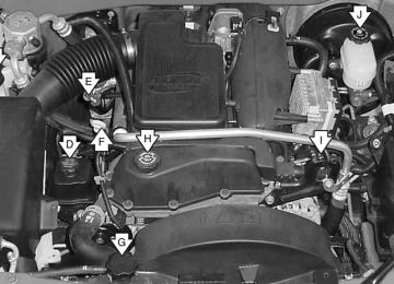
(cid:127) (cid:127) Cooling System When you decide it’s safe to lift the hood, here’s what you’ll see:
L6 Engine
V8 Engine
A. Coolant Recovery Tank B. Radiator Pressure Cap C. Engine Fan
If the coolant inside the coolant recovery tank is boiling, don’t do anything else until it cools down. The vehicle should be parked on a level surface.
5-32
The coolant level should be at least up to the FULL COLD mark. If it isn’t, you may have a leak at the pressure cap or in the radiator hoses, heater hoses, radiator, water pump or somewhere else in the cooling system.
{CAUTION:
Heater and radiator hoses, and other engine parts, can be very hot. Do not touch them. If you do, you can be burned.
CAUTION:
(Continued)
CAUTION:
(Continued)
Do not run the engine if there is a leak. If you run the engine, it could lose all coolant. That could cause an engine fire, and you could be burned. Get any leak fixed before you drive the vehicle.
If there seems to be no leak, start the engine again. The engine cooling fan speed should increase when idle speed is doubled by pushing the accelerator pedal down. If it doesn’t, your vehicle needs service. Turn off the engine. Notice: Engine damage from running your engine without coolant is not covered by your warranty. Notice: Using coolant other than DEX-COOL® may cause premature engine, heater core or radiator corrosion. In addition, the engine coolant may require changing sooner, at 30,000 miles (50 000 km) or 24 months, whichever occurs first. Any repairs would not be covered by your warranty. Always use DEX-COOL®(silicate-free) coolant in your vehicle.
5-33
How to Add Coolant to the Coolant Recovery Tank If you haven’t found a problem yet, but the coolant level isn’t at the FULL COLD mark, add a 50/50 mixture of clean, drinkable water and DEX-COOL® engine coolant at the coolant recovery tank. See Engine Coolant on page 5-27 for more information.
{CAUTION:
Adding only plain water to your cooling system can be dangerous. Plain water, or some other liquid such as alcohol, can boil before the proper coolant mixture will. Your vehicle’s coolant warning system is set for the proper coolant mixture. With plain water or the wrong mixture, your engine could get too hot but you would not get the overheat warning. Your engine could catch fire and you or others could be burned. Use a 50/50 mixture of clean, drinkable water and DEX-COOL® coolant.
5-34
In cold weather, water can freeze and crack
Notice: the engine, radiator, heater core and other parts. Use the recommended coolant and the proper coolant mixture.
{CAUTION:
You can be burned if you spill coolant on hot engine parts. Coolant contains ethylene glycol and it will burn if the engine parts are hot enough. Do not spill coolant on a hot engine.
When the coolant in the coolant recovery tank is at the FULL COLD mark, start your vehicle. If the overheat warning continues, there’s one more thing you can try. You can add the proper coolant mixture directly to the radiator, but be sure the cooling system is cool before you do it.
{CAUTION:
Steam and scalding liquids from a hot cooling system can blow out and burn you badly. They are under pressure, and if you turn the radiator pressure cap — even a little — they can come out at high speed. Never turn the cap when the cooling system, including the radiator pressure cap, is hot. Wait for the cooling system and radiator pressure cap to cool if you ever have to turn the pressure cap.
5-35
How to Add Coolant to the Radiator
1. You can remove the radiator pressure cap when
the cooling system, including the radiator pressure cap and upper radiator hose, is no longer hot. Turn the pressure cap slowly counterclockwise about one full turn. If you hear a hiss, wait for that to stop. A hiss means there is still some pressure left.
5-36
2. Then keep turning the pressure cap. Remove the
pressure cap.
3. Fill the radiator with the proper DEX-COOL®
coolant mixture, up to the base of the filler neck. See Engine Coolant on page 5-27 for more information about the proper coolant mixture.
4. Then fill the coolant recovery tank to the FULL
COLD mark.
5. Put the cap back on the coolant recovery tank,
but leave the radiator pressure cap off.
5-37
8. Then replace the pressure cap. At any time during
this procedure if coolant begins to flow out of the filler neck, reinstall the pressure cap. Be sure the pressure cap is hand-tight.
Engine Fan Noise This vehicle has a clutched engine cooling fan. When the clutch is engaged, the fan spins faster to provide more air to cool the engine. In most everyday driving conditions the clutch is not engaged. This improves fuel economy and reduces fan noise. Under heavy vehicle loading, trailer towing, and/or high outside temperatures, the fan speed increases when the clutch engages. So you may hear an increase in fan noise. This is normal and should not be mistaken as the transmission slipping or making extra shifts. It is merely the cooling system functioning properly. The fan will slow down when additional cooling is not required and the clutch disengages. You may also hear this fan noise when you start the engine. It will go away as the fan clutch disengages.
6. Start the engine and let it run until you can feel the
upper radiator hose getting hot. Watch out for the engine cooling fan.
7. By this time, the coolant level inside the radiator filler neck may be lower. If the level is lower, add more of the proper DEX-COOL® coolant mixture through the filler neck until the level reaches the base of the filler neck.
5-38
Power Steering Fluid
The power steering fluid reservoir is located in the engine compartment. It is on the passenger’s side of vehicles with the L6 engine and is on the driver’s side of vehicles with the V8 engine. See Engine Compartment Overview on page 5-14
for reservoir location.When to Check Power Steering Fluid It is not necessary to regularly check power steering fluid unless you suspect there is a leak in the system or you hear an unusual noise. A fluid loss in this system could indicate a problem. Have the system inspected and repaired.
How to Check Power Steering Fluid Turn the key off, let the engine compartment cool down, wipe the cap and the top of the reservoir clean, then unscrew the cap and wipe the dipstick with a clean rag. Replace the cap and completely tighten it. Then remove the cap again and look at the fluid level on the dipstick. For vehicles with the L6 engine, the level should be at the C (cold) mark. For vehicles with the V8 engine, the level should be at the FULL mark. If necessary, add only enough fluid to bring the level up to the mark. What to Use To determine what kind of fluid to use, see Recommended Fluids and Lubricants on page 6-12. Always use the proper fluid. Failure to use the proper fluid can cause leaks and damage hoses and seals.
5-39
Windshield Washer Fluid What to Use When you need windshield washer fluid, be sure to read the manufacturer’s instructions before use. If you will be operating your vehicle in an area where the temperature may fall below freezing, use a fluid that has sufficient protection against freezing. Adding Washer Fluid
Open the cap with the washer symbol on it. Add washer fluid until the tank is full. See Engine Compartment Overview on page 5-14 for reservoir location.
Notice: (cid:127) When using concentrated washer fluid, follow the
manufacturer’s instructions for adding water.
(cid:127) Do not mix water with ready-to-use washer fluid.
Water can cause the solution to freeze and damage your washer fluid tank and other parts of the washer system. Also, water does not clean as well as washer fluid. Fill your washer fluid tank only three-quarters full when it is very cold. This allows for expansion if freezing occurs, which could damage the tank if it is completely full.
(cid:127) Do not use engine coolant (antifreeze) in your windshield washer. It can damage your washer system and paint.
5-40
(cid:127) Brakes Brake Fluid
Your brake master cylinder reservoir is filled with DOT-3
brake fluid. See Engine Compartment Overview on page 5-14 for the location of the reservoir. There are only two reasons why the brake fluid level in the reservoir might go down. The first is that the brake fluid goes down to an acceptable level during normal brake lining wear. When new linings are put in, the fluid level goes back up. The other reason is that fluid is leaking out of the brake system.If it is, you should have your brake system fixed, since a leak means that sooner or later your brakes will not work well, or will not work at all. So, it is not a good idea to “top off” your brake fluid. Adding brake fluid will not correct a leak. If you add fluid when your linings are worn, then you will have too much fluid when you get new brake linings. You should add (or remove) brake fluid, as necessary, only when work is done on the brake hydraulic system.
{CAUTION:
If you have too much brake fluid, it can spill on the engine. The fluid will burn if the engine is hot enough. You or others could be burned, and your vehicle could be damaged. Add brake fluid only when work is done on the brake hydraulic system. See “Checking Brake Fluid” in this section.
Refer to the Maintenance Schedule to determine when to check your brake fluid. See Scheduled Maintenance on page 6-4.
5-41
Checking Brake Fluid You can check the brake fluid without taking off the cap.
Always clean the brake fluid reservoir cap and the area around the cap before removing it. This will help keep dirt from entering the reservoir.
Just look at the brake fluid reservoir. The fluid level should be above MIN. If it is not, have your brake system checked to see if there is a leak.
After work is done on the brake hydraulic system, make sure the level is above the MIN but not over the MAX mark. What to Add When you do need brake fluid, use only DOT-3 brake fluid. Use new brake fluid from a sealed container only. See Recommended Fluids and Lubricants on page 6-12.
5-42
{CAUTION:
With the wrong kind of fluid in your brake system, your brakes may not work well, or they may not even work at all. This could cause a crash. Always use the proper brake fluid.
Notice: (cid:127) Using the wrong fluid can badly damage brake system parts. For example, just a few drops of mineral-based oil, such as engine oil, in your brake system can damage brake system parts so badly that they will have to be replaced. Do not let someone put in the wrong kind of fluid. If you spill brake fluid on your vehicle’s painted surfaces, the paint finish can be damaged. Be careful not to spill brake fluid on your vehicle. If you do, wash it off immediately. See Appearance Care on page 5-92.
(cid:127) Brake Wear Your vehicle has four-wheel disc brakes. Disc brake pads have built-in wear indicators that make a high-pitched warning sound when the brake pads are worn and new pads are needed. The sound may come and go or be heard all the time your vehicle is moving (except when you are pushing on the brake pedal firmly).
{CAUTION:
The brake wear warning sound means that soon your brakes will not work well. That could lead to an accident. When you hear the brake wear warning sound, have your vehicle serviced.
Notice: Continuing to drive with worn-out brake pads could result in costly brake repair. Some driving conditions or climates may cause a brake squeal when the brakes are first applied or lightly applied. This does not mean something is wrong with your brakes. Properly torqued wheel nuts are necessary to help prevent brake pulsation. When tires are rotated, inspect brake pads for wear and evenly tighten wheel nuts in the proper sequence to GM torque specifications. Brake linings should always be replaced as complete axle sets. Brake Pedal Travel See your dealer if the brake pedal does not return to normal height, or if there is a rapid increase in pedal travel. This could be a sign of brake trouble. Brake Adjustment Every time you make a brake stop, your disc brakes adjust for wear.
5-43
Replacing Brake System Parts The braking system on a vehicle is complex. Its many parts have to be of top quality and work well together if the vehicle is to have really good braking. Your vehicle was designed and tested with top-quality GM brake parts. When you replace parts of your braking system — for example, when your brake linings wear down and you need new ones put in — be sure you get new approved GM replacement parts. If you do not, your brakes may no longer work properly. For example, if someone puts in brake linings that are wrong for your vehicle, the balance between your front and rear brakes can change — for the worse. The braking performance you have come to expect can change in many other ways if someone puts in the wrong replacement brake parts.
Battery Your new vehicle comes with a maintenance free ACDelco® battery. When it is time for a new battery, get one that has the replacement number shown on the original battery’s label. We recommend an ACDelco® battery. See Engine Compartment Overview on page 5-14 for battery location. Warning: Battery posts, terminals and related accessories contain lead and lead compounds, chemicals known to the State of California to cause cancer and reproductive harm. Wash hands after handling.
5-44
Vehicle Storage If you are not going to drive your vehicle for 25 days or more, remove the black, negative (−) cable from the battery. This will help keep your battery from running down.
Jump Starting If your battery has run down, you may want to use another vehicle and some jumper cables to start your vehicle. But please use the following steps to do it safely.
{CAUTION:
Batteries have acid that can burn you and gas that can explode. You can be badly hurt if you are not careful. See Jump Starting on page 5-45
for tips on working around a battery without getting hurt.Contact your dealer to learn how to prepare your vehicle for longer storage periods. Also, for your audio system, see Theft-Deterrent Feature (RDS Radios) on page 3-112.
{CAUTION:
Batteries can hurt you. They can be dangerous because:
(cid:127) They contain acid that can burn you. (cid:127) They contain gas that can explode
(cid:127) They contain enough electricity
or ignite.
to burn you.
If you do not follow these steps exactly, some or all of these things can hurt you.
Ignoring these steps could result in costly
Notice: damage to your vehicle that would not be covered by your warranty. Trying to start your vehicle by pushing or pulling it will not work, and it could damage your vehicle.
5-45
3. Turn off the ignition on both vehicles. Unplug
unnecessary accessories plugged into the cigarette lighter or accessory power outlets (if equipped). Turn off the radio and all lamps that aren’t needed. This will avoid sparks and help to save both batteries. And it could save your radio!
4. Open both hoods and locate the batteries. Find the positive (+) and negative (−) terminals on each battery. Your vehicle has a remote negative (−) jump starting terminal. You should always use this remote terminal instead of the terminal on the battery. The remote negative (−) terminal is located on the front engine lift bracket on vehicles with the L6 engine or the engine accessory drive bracket for vehicles with the V8 engine and is marked GND. See Engine Compartment Overview on page 5-14 for more information on location.
1. Check the other vehicle. It must have a 12-volt
battery with a negative ground system.
If the other vehicle’s system is not a 12-volt
Notice: system with a negative ground, both vehicles can be damaged. Only use vehicles with 12-volt systems with negative grounds to jump start your vehicle. 2. Get the vehicles close enough so the jumper cables can reach, but be sure the vehicles aren’t touching each other. If they are, it could cause a ground connection you don’t want. You wouldn’t be able to start your vehicle, and the bad grounding could damage the electrical systems. To avoid the possibility of the vehicles rolling, set the parking brake firmly on both vehicles involved in the jump start procedure. Put an automatic transmission in PARK (P) or a manual transmission in NEUTRAL before setting the parking brake. If you have a four- wheel-drive vehicle, be sure the transfer case is not in NEUTRAL.
If you leave your radio or other accessories
Notice: on during the jump starting procedure, they could be damaged. The repairs would not be covered by your warranty. Always turn off your radio and other accessories when jump starting your vehicle.
5-46
{CAUTION:
{CAUTION:
Using a match near a battery can cause battery gas to explode. People have been hurt doing this, and some have been blinded. Use a flashlight if you need more light. Be sure the battery has enough water. You do not need to add water to the ACDelco® battery installed in your new vehicle. But if a battery has filler caps, be sure the right amount of fluid is there. If it is low, add water to take care of that first. If you do not, explosive gas could be present. Battery fluid contains acid that can burn you. Do not get it on you. If you accidentally get it in your eyes or on your skin, flush the place with water and get medical help immediately.
Fans or other moving engine parts can injure you badly. Keep your hands away from moving parts once the engine is running.
5. Check that the jumper cables don’t have loose
or missing insulation. If they do, you could get a shock. The vehicles could be damaged too. Before you connect the cables, here are some basic things you should know. Positive (+) will go to positive (+) or to a remote positive (+) terminal if the vehicle has one. Negative (−) will go to a heavy, unpainted metal engine part or to a remote negative (−) terminal if the vehicle has one. Don’t connect positive (+) to negative (−) or you’ll get a short that would damage the battery and maybe other parts too. And don’t connect the negative (−) cable to the negative (−) terminal on the dead battery because this can cause sparks.
5-47
6. Connect the red
positive (+) cable to the positive (+) terminal of the dead battery. Use a remote positive (+) terminal if the vehicle has one.
8. Now connect the black
negative (−) cable to the negative (−) terminal of the good battery. Use a remote negative (−) terminal if the vehicle has one.
7. Don’t let the other end touch metal. Connect it to the positive (+) terminal of the good battery. Use a remote positive (+) terminal if the vehicle has one.
Don’t let the other end touch anything until the next step. The other end of the negative (−) cable doesn’t go to the dead battery. It goes to a heavy, unpainted metal engine part or to the remote negative (−) terminal on the vehicle with the dead battery. On the L6 engine, the remote negative (−) terminal on your vehicle is located on the front engine lift bracket and is marked GND. On the V8 engine, the remote negative (–) terminal is located on the accessory drive bracket and is marked GND.
5-48
9. Connect the other end
of the negative (−) cable to the remote negative (−) terminal on the vehicle with the dead battery.
11. Try to start the vehicle that had the dead battery. If it won’t start after a few tries, it probably needs service.
If the jumper cables are removed in the
Notice: wrong order, electrical shorting may occur and damage the vehicle. The repairs would not be covered by your warranty. Remove the jumper cables in the correct order, making sure that the cables do not touch each other or other metal.
10. Now start the vehicle with the good battery and
run the engine for a while.
5-49
To disconnect the jumper cables from both vehicles, do the following: 1. Disconnect the black negative (−) cable from the
vehicle that had the dead battery.
2. Disconnect the black negative (−) cable from the
vehicle with the good battery.
3. Disconnect the red positive (+) cable from the
vehicle with the good battery.
4. Disconnect the red positive (+) cable from the
other vehicle.
Jumper Cable Removal
A. Heavy, Unpainted Metal Engine Part or
Remote Negative (−) Terminal
B. Good Battery or Remote Positive (+) and
Remote Negative (−) Terminals
C. Dead Battery or Remote Positive (+) Terminal
5-50
All-Wheel Drive Transfer Case When to Check Lubricant It is not necessary to regularly check fluid unless you suspect there is a leak or you hear an unusual noise. A fluid loss could indicate a problem. Have it inspected and repaired. How to Check Lubricant
To get an accurate reading, the vehicle should be on a level surface.
If the level is below the bottom of the filler plug hole, you’ll need to add some lubricant. Add enough lubricant to raise the level to the bottom of the filler plug hole. Use care not to overtighten the plug. What to Use To determine what kind of lubricant to use, see Recommended Fluids and Lubricants on page 6-12. Rear Axle When to Check Lubricant It is not necessary to regularly check rear axle fluid unless you suspect there is a leak or you hear an unusual noise. A fluid loss could indicate a problem. Have it inspected and repaired.
5-51
How to Check Lubricant
To get an accurate reading, the vehicle should be on a level surface. The proper level is from 0 to 3/8 inch (0 to 10 mm) below the bottom of the filler plug hole. What to Use To determine what kind of lubricant to use, see Recommended Fluids and Lubricants on page 6-12.
5-52
Front Axle When to Check Lubricant It is not necessary to regularly check front axle fluid unless you suspect there is a leak or you hear an unusual noise. A fluid loss could indicate a problem. Have it inspected and repaired. How to Check Lubricant
To get an accurate reading, the vehicle should be on a level surface. If the level is below the bottom of the filler plug hole, you may need to add some lubricant. When the differential is cold, add enough lubricant to raise the level to 1/2 inch (12 mm) below the filler plug hole. When the differential is at operating temperature (warm), add enough lubricant to raise the level to the bottom of the filler plug hole. What to Use To determine what kind of lubricant to use, see Recommended Fluids and Lubricants on page 6-12.
5-53
Taillamps and Turn Signal Lamps 1. Open the liftgate.
2. Remove the two screws from the lamp assembly.
3. Pull the assembly away from the vehicle.
Bulb Replacement For the type of bulbs, see Replacement Bulbs on page 5-55. For any bulb changing procedure not listed in this section, contact your dealer.
Headlamps 1. Open the hood. 2. Remove the grille by grasping and pulling
it forward.
3. Lift the inner quick release clips. 4. Pull the headlamp assembly away from
the vehicle.
5. Remove the cover from the headlamp bulb. 6. Disconnect the wiring harness. 7. Remove the headlamp bulb by turning
the socket counterclockwise.
8. To install the replacement bulb,
reverse Steps 1 through 6.
5-54
4. Unclip the wiring harness (A) and remove the
three socket retaining screws (B).
5. Remove the socket by releasing the retaining tabs. 6. Holding the socket, pull the bulb to release it from
the socket.
7. To install the replacement bulbs, reverse
Steps 1 through 6.
Replacement Bulbs
Exterior Lamp
Bulb Number
Halogen Headlamps Low Beam High Beam Front Sidemarker Lamp Front Park Lamp Front Turn Lamp Taillamps Rear Turn Signal Lamps
9006 HB4
9005 HB3194
1943757 A 3057
3057For any bulb not listed here, contact your dealer.
5-55
Windshield Wiper Blade Replacement Windshield wiper blades should be inspected at least twice a year for wear or cracking. Notice: Allowing the wiper blade arm to touch the windshield when no wiper blade is installed could damage the windshield. Any damage that occurs would not be covered by your warranty. Do not allow the wiper blade arm to touch the windshield. 1. To remove the old wiper blades, lift the wiper arm
until it locks into a vertical position.
5-56
A. Blade Assembly B. Arm Assembly C. Locking Tab
D. Blade Pivot E. Hook Slot F. Arm Hook
2. Press down on the blade assembly pivot locking
tab. Pull down on the blade assembly to release it from the wiper arm hook.
3. Remove the insert from the blade assembly.
The insert has two notches at one end that are locked by the bottom claws of the blade assembly. At the notched end, pull the insert from the blade assembly.
4. To install the new wiper insert, slide the insert (D),
notched end last, into the end with two blade claws (A). Slide the insert all the way through the blade claws at the opposite end (B). The plastic caps (C) will be forced off as the insert is fully inserted.
5-57
5. Be sure that the notches are locked by the bottom claws. Make sure that all other claws are properly locked on both sides of the insert slots.
6. Put the blade assembly pivot in the wiper arm hook.
Pull up until the pivot locking tab locks in the hook slot.
7. Carefully lower the wiper arm and blade assembly
onto the windshield.
Backglass Wiper Blade Replacement See Windshield Wiper Blade Replacement on page 5-56
for instructions on how to change the backglass wiper blade. The backglass wiper blade will not lock in a vertical position like the windshield wiper blade, so care should be used when pulling it away from the vehicle.A. Claw in Notch B. Correct Installation
C. Incorrect
Installation
5-58
Tires Your new vehicle comes with high-quality tires made by a leading tire manufacturer. If you ever have questions about your tire warranty and where to obtain service, see your GM Warranty booklet for details. For additional information refer to the tire manufacturer’s booklet included with your vehicle’s Owner’s Manual.
{CAUTION:
Poorly maintained and improperly used tires are dangerous.
(cid:127) Overloading your tires can cause
overheating as a result of too much friction. You could have an air-out and a serious accident. See “Loading Your Vehicle” in the Index.
CAUTION:
(Continued)
CAUTION:
(Continued)
(cid:127) Underinflated tires pose the same danger as overloaded tires. The resulting accident could cause serious injury. Check all tires frequently to maintain the recommended pressure. Tire pressure should be checked when your tires are cold.
(cid:127) Overinflated tires are more likely to be cut,
punctured or broken by a sudden impact — such as when you hit a pothole. Keep tires at the recommended pressure.
(cid:127) Worn, old tires can cause accidents. If your
tread is badly worn, or if your tires have been damaged, replace them.
Tire Sidewall Labeling Useful information about a tire is molded into the sidewall. The following illustrations are examples of a typical P-Metric and a LT-Metric tire sidewall.
5-59
(A) Tire Size Code: The tire size code is a combination of letters and numbers used to define a particular tire’s width, height, aspect ratio, construction type and service description. See the “Tire Size Code” illustration later in this section for more detail.
(B) Tire Performance Criteria Specification (TPC Spec): Original equipment tires designed to GM’s specific tire performance criteria have a TPC specification code molded onto the sidewall. GM’s TPC specifications meet or exceed all federal safety guidelines.
(C) Department of Transportation (DOT): The Department of Transportation (DOT) code indicates that the tire is in compliance with the U.S. Department of Transportation Motor Vehicle Safety Standards.
(D) Tire Identification Number (TIN): The letters and numbers following DOT code are the Tire Identification Number (TIN). The TIN shows the manufacturer and plant code, tire size, and date the tire was manufactured. The TIN is molded onto both sides of the tire, although only one side may have the date of manufacture.
P-Metric Tire
5-60
(E) Tire Ply Material: The type of cord and number of plies in the sidewall and under the tread.
(F) Uniform Tire Quality Grading (UTQG): Tire manufacturers are required to grade tires based on three performance factors: treadwear, traction and temperature resistance. For more information, see Uniform Tire Quality Grading on page 5-72.
(G) Maximum Cold Inflation Load Limit: Maximum load that can be carried and the maximum pressure needed to support that load. For information on recommended tire pressure see Inflation - Tire Pressure on page 5-67 and Loading Your Vehicle on page 4-46.
LT-Metric Tire
5-61
(A) Tire Size: The tire size code is a combination of letters and numbers used to define a particular tire’s width, height, aspect ratio, construction type and service description. See the “Tire Size” illustration later in this section for more detail.
(B) Tire Performance Criteria Specification (TPC Spec): Original equipment tires designed to GM’s specific tire performance criteria have a TPC specification code molded onto the sidewall. GM’s TPC specifications meet or exceed all federal safety guidelines.
(C) Dual Tire Maximum Load: Maximum load that can be carried and the maximum pressure needed to support that load when used in a dual configuration. For information on recommended tire pressure see Inflation - Tire Pressure on page 5-67 and Loading Your Vehicle on page 4-46.
(D) Department of Transportation (DOT): The Department of Transportation (DOT) code indicates that the tire is in compliance with the U.S. Department of Transportation Motor Vehicle Safety Standards.
(E) Tire Identification Number (TIN): The letters and numbers following DOT code are the Tire Identification Number (TIN). The TIN shows the manufacturer and plant code, tire size, and date the tire was manufactured. The TIN is molded onto both sides of the tire, although only one side may have the date of manufacture.
(F) Tire Ply Material: The type of cord and number of plies in the sidewall and under the tread.
(G) Single Tire Maximum Load: Maximum load that can be carried and the maximum pressure needed to support that load when used as a single. For information on recommended tire pressure see Inflation - Tire Pressure on page 5-67 and Loading Your Vehicle on page 4-46.
5-62
Tire Size The following examples show the different parts of a tire size.
Passenger (P-Metric) Tire
(A) Passenger (P-Metric) Tire: The United States version of a metric tire sizing system. The letter “P” as the first character in the tire size means a passenger vehicle tire engineered to standards set by the U.S. Tire and Rim Association.
(B) Tire Width: The three-digit number indicates the tire section width in millimeters from sidewall to sidewall.
(C) Aspect Ratio: A two-digit number that indicates the tire height-to-width measurements. For example, if the tire size aspect ratio is “75,” as shown in item “C” of the illustration, it would mean that the tire’s sidewall is 75% as high as it is wide.
(D) Construction Code: A letter code is used to indicate the type of ply construction in the tire. The letter “R” means radial ply construction; the letter “D” means diagonal or bias ply construction; and the letter “B” means belted-bias ply construction.
(E) Rim Diameter: Diameter of the wheel in inches.
(F) Service Description: The service description indicates the load range and speed rating of a tire. The load index can range from 1 to 279. Speed ratings range from “A” to “Z”.
5-63
(D) Construction Code: A letter code is used to indicate the type of ply construction in the tire. The letter “R” means radial ply construction; the letter “D” means diagonal or bias ply construction; and the letter “B” means belted-bias ply construction.
(E) Rim Diameter: Diameter of the wheel in inches.
(F) Service Description: The service description indicates the load range and speed rating of a tire. The load index can range from 1 to 279. Speed ratings range from “A” to “Z”. The light truck tire size example above shows dual or single tire configurations. Tire Terminology and Definitions
Air Pressure: The amount of air inside the tire pressing outward on each square inch of the tire. Air pressure is expressed in pounds per square inch (psi) or kilopascal (kPa).
Accessory Weight: This means the combined weight of optional accessories. Some examples of optional accessories are, automatic transmission, power steering, power brakes, power windows, power seats, and air conditioning.
Aspect Ratio: The relationship of a tire’s height to its width.
Light Truck (LT-Metric) Tire
(A) Light Truck (LT-Metric) Tire: The United States version of a metric tire sizing system. The letter “LT” as the first two characters in the tire size means a light truck tire engineered to standards set by the U. S. Tire and Rim Association.
(B) Tire Width: The three-digit number indicates the tire section width in millimeters from sidewall to sidewall.
(C) Aspect Ratio: A two-digit number that indicates the tire height-to-width measurements. For example, if the tire size aspect ratio is “75,” as shown in item “C” of the illustration, it would mean that the tire’s sidewall is 75% as high as it is wide.
5-64
Belt: A rubber coated layer of cords that is located between the plies and the tread. Cords may be made from steel or other reinforcing materials.
Bead: The tire bead contains steel wires wrapped by steel cords that hold the tire onto the rim.
Bias Ply Tire: A pneumatic tire in which the plies are laid at alternate angles less than 90 degrees to the centerline of the tread.
Cold Inflation Pressure: The amount of air pressure in a tire, measured in pounds per square inch (psi) or kilopascals (kPa) before a tire has built up heat from driving. See Inflation - Tire Pressure on page 5-67.
Curb Weight: This means the weight of a motor vehicle with standard and optional equipment including the maximum capacity of fuel, oil and coolant, but without passengers and cargo.
DOT Markings: A code molded into the sidewall of a tire signifying that the tire is in compliance with the U.S. Department of Transportation motor vehicle safety standards. The DOT code includes the Tire Identification Number (TIN), an alphanumeric designator which can also identify the tire manufacturer, production plant, brand and date of production.
GVWR: Gross Vehicle Weight Rating, see Loading Your Vehicle on page 4-46.
GAWR FRT: Gross Axle Weight Rating for the front axle, see Loading Your Vehicle on page 4-46.
GAWR RR: Gross Axle Weight Rating for the rear axle, see Loading Your Vehicle on page 4-46.
Intended Outboard Sidewall: The side of an asymmetrical tire, that must always face outward when mounted on a vehicle.
Kilopascal (kPa): The metric unit for air pressure. There are 6.9 kPa’s to one psi.
Light Truck (LT-Metric) Tire: A tire used on light duty trucks and some multipurpose passenger vehicles.
Load Index: An assigned number ranging from 1 to 279
that corresponds to the load carrying capacity of a tire.Maximum Inflation Pressure: The maximum air pressure to which a cold tire may be inflated. The maximum air pressure is molded onto the sidewall.
Maximum Load Rating: The load rating for a tire at the maximum permissible inflation pressure for that tire.
5-65
Maximum Loaded Vehicle Weight: The sum of curb weight; accessory weight; vehicle capacity weight; and production options weight.
Radial Ply tire: A pneumatic tire in which the ply cords that extend to the beads are laid at 90 degrees to the centerline of the tread.
Normal Occupant Weight: The number of occupants a vehicle is designed to seat multiplied by 150
pounds (68 kg). See Loading Your Vehicle on page 4-46.Occupant Distribution: Designated seating positions.
Outward Facing Sidewall: The side of a asymmetrical tire that has a particular side that faces outward when mounted on a vehicle. The side of the tire that contains a whitewall, bears white lettering or bears manufacturer, brand and or model name molding that is higher or deeper than the same moldings on the other sidewall of the tire.
Passenger (P-Metric) Tire: A tire used on passenger cars and some light duty trucks and multipurpose vehicles.
Recommended Inflation Pressure: Vehicle manufacturer’s recommended tire inflation pressure and shown on the tire placard. See Inflation - Tire Pressure on page 5-67 and Loading Your Vehicle on page 4-46.
Rim: A metal support for a tire and upon which the tire beads are seated.
Sidewall: The portion of a tire between the tread and the bead.
Speed Rating: An alphanumeric code assigned to a tire indicating the maximum speed at which a tire can operate.
Traction: The friction between the tire and the road surface. The amount of grip provided.
Tread: The portion of a tire that comes into contact with the road.
Treadwear Indicators: Narrow bands, sometimes called “wear bars,” that show across the tread of a tire when only 2/32 inch of tread remains. See When It Is Time for New Tires on page 5-70.
5-66
UTQGS: Uniform Tire Quality Grading Standards, a tire information system that provides consumers with ratings for a tire’s traction, temperature and treadwear. Ratings are determined by tire manufacturers using government testing procedures. The ratings are molded into the sidewall of the tire. See Uniform Tire Quality Grading on page 5-72.
Vehicle Capacity Weight: The number of designated seating positions multiplied by 150 lbs. (68 kg) plus the rated cargo load. See Loading Your Vehicle on page 4-46.
Vehicle Maximum Load on the Tire: Load on an individual tire due to curb weight, accessory weight, occupant weight and cargo weight.
Vehicle Placard: A label permanently attached to a vehicle showing the original equipment tire size and recommended inflation pressure. See Loading Your Vehicle on page 4-46.
Inflation - Tire Pressure The tire and loading information label, shows the correct inflation pressures for your tires when they’re cold. “Cold” means your vehicle has been sitting for at least three hours or driven no more than 1 mile (1.6 km). See Loading Your Vehicle on page 4-46, for the location of your vehicle’s tire and loading information label.
Notice: Don’t let anyone tell you that underinflation or overinflation is all right. It’s not. If your tires don’t have enough air (underinflation), you can get the following:
Too much flexing Too much heat Tire overloading
(cid:127) Bad wear (cid:127) Bad handling (cid:127) Bad fuel economy If your tires have too much air (overinflation), you can get the following: (cid:127) Unusual wear (cid:127) Bad handling (cid:127) Rough ride (cid:127) Needless damage from road hazards When to Check Check your tires once a month or more. Also, check the tire pressure of the spare tire.
5-67
(cid:127) (cid:127) (cid:127) How to Check Use a good quality pocket-type gage to check tire pressure. You can’t tell if your tires are properly inflated simply by looking at them. Radial tires may look properly inflated even when they’re underinflated. Check the tire’s inflation pressure when the tires are cold. cold means your vehicle has been sitting for at least three hours or driven no more than 1 mile (1.6 km). Remove the valve cap from the tire valve stem. Press the tire gage firmly onto the valve to get a pressure measurement. If the cold tire inflation pressure matches the recommended pressure on the tire and loading information label, no further adjustment is necessary. If the pressure is low, add air until you reach the recommended amount. If you overfill the tire, release air by pushing on the metal stem in the center of the tire valve. Recheck the tire pressure with the tire gage. Be sure to put the valve caps back on the valve stems. They help prevent leaks by keeping out dirt and moisture.
Tire Inspection and Rotation Tires should be rotated every 5,000 to 8,000 miles (8 000 to 13 000 km). Any time you notice unusual wear, rotate your tires as soon as possible and check wheel alignment. Also check for damaged tires or wheels. See When It Is Time for New Tires on page 5-70 and Wheel Replacement on page 5-74 for more information. Make sure the spare tire is stored securely. Push, pull, and then try to rotate or turn the tire. If it moves, use the wheel wrench to tighten the cable. For information on storing or removing the spare tire, see Changing a Flat Tire on page 5-79.
5-68
The purpose of regular rotation is to achieve more uniform wear for all tires on the vehicle. The first rotation is the most important. See Scheduled Maintenance on page 6-4.
{CAUTION:
When rotating your tires, always use the correct rotation pattern shown here. After the tires have been rotated, adjust the front and rear inflation pressures as shown on the Certification/Tire label or the Tire and Loading Information label. Make certain that all wheel nuts are properly tightened. See “Wheel Nut Torque” under Capacities and Specifications on page 5-113.
Rust or dirt on a wheel, or on the parts to which it is fastened, can make wheel nuts become loose after a time. The wheel could come off and cause an accident. When you change a wheel, remove any rust or dirt from places where the wheel attaches to the vehicle. In an emergency, you can use a cloth or a paper towel to do this; but be sure to use a scraper or wire brush later, if you need to, to get all the rust or dirt off. See “Changing a Flat Tire” in the Index.
5-69
When It Is Time for New Tires
One way to tell when it’s time for new tires is to check the treadwear indicators, which will appear when your tires have only 1/16 inch (1.6 mm) or less of tread remaining. Some commercial truck tires may not have treadwear indicators.
You need a new tire if any of the following statements are true: (cid:127) You can see the indicators at three or more places
around the tire.
(cid:127) You can see cord or fabric showing through the
tire’s rubber. The tread or sidewall is cracked, cut or snagged deep enough to show cord or fabric. The tire has a bump, bulge or split. The tire has a puncture, cut or other damage that can’t be repaired well because of the size or location of the damage.
5-70
(cid:127) (cid:127) (cid:127) Buying New Tires To find out what kind and size of tires you need, look at the Certification/Tire label or the Tire and Loading Information label. For examples of these labels and their location on your vehicle, see Loading Your Vehicle on page 4-46. The tires installed on your vehicle when it was new had a Tire Performance Criteria Specification (TPC Spec) number on each tire’s sidewall. When you get new tires, General Motors recommends that you get tires with that same TPC Spec number. That way your vehicle will continue to have tires that are designed to give proper endurance, handling, speed rating, load range, traction, ride and other things during normal service on your vehicle. If your tires have an all-season tread design, the TPC number will be followed by an “MS” (for mud and snow). If you ever replace your tires with those not having a TPC Spec number, make sure they are the same size, load range, speed rating and construction type (bias, bias-belted or radial) as your original tires.
{CAUTION:
Mixing tires could cause you to lose control while driving. If you mix tires of different sizes or types (radial and bias-belted tires) the vehicle may not handle properly, and you could have a crash. Using tires of different sizes may also cause damage to your vehicle. Be sure to use the same size and type tires on all wheels.
{CAUTION:
If you use bias-ply tires on your vehicle, the wheel rim flanges could develop cracks after many miles of driving. A tire and/or wheel could fail suddenly, causing a crash. Use only radial-ply tires with the wheels on your vehicle.
5-71
Uniform Tire Quality Grading Quality grades can be found where applicable on the tire sidewall between tread shoulder and maximum section width. For example: Treadwear 200 Traction AA Temperature A The following information relates to the system developed by the United States National Highway Traffic Safety Administration, which grades tires by treadwear, traction and temperature performance. (This applies only to vehicles sold in the United States.) The grades are molded on the sidewalls of most passenger car tires. The Uniform Tire Quality Grading system does not apply to deep tread, winter-type snow tires, space-saver or temporary use spare tires, tires with nominal rim diameters of 10 to 12 inches (25 to 30 cm), or to some limited-production tires. While the tires available on General Motors passenger cars and light trucks may vary with respect to these grades, they must also conform to federal safety requirements and additional General Motors Tire Performance Criteria (TPC) standards.
Treadwear The treadwear grade is a comparative rating based on the wear rate of the tire when tested under controlled conditions on a specified government test course. For example, a tire graded 150 would wear one and a half (1.5) times as well on the government course as a tire graded 100. The relative performance of tires depends upon the actual conditions of their use, however, and may depart significantly from the norm due to variations in driving habits, service practices and differences in road characteristics and climate. Traction – AA, A, B, C The traction grades, from highest to lowest, are AA, A, B, and C. Those grades represent the tire’s ability to stop on wet pavement as measured under controlled conditions on specified government test surfaces of asphalt and concrete. A tire marked C may have poor traction performance. Warning: The traction grade assigned to this tire is based on straight-ahead braking traction tests, and does not include acceleration, cornering, hydroplaning, or peak traction characteristics.
5-72
Wheel Alignment and Tire Balance The wheels on your vehicle were aligned and balanced carefully at the factory to give you the longest tire life and best overall performance. Scheduled wheel alignment and wheel balancing are not needed. However, if you notice unusual tire wear or your vehicle pulling one way or the other, the alignment may need to be reset. If you notice your vehicle vibrating when driving on a smooth road, your wheels may need to be rebalanced.
Temperature – A, B, C The temperature grades are A (the highest), B, and C, representing the tire’s resistance to the generation of heat and its ability to dissipate heat when tested under controlled conditions on a specified indoor laboratory test wheel. Sustained high temperature can cause the material of the tire to degenerate and reduce tire life, and excessive temperature can lead to sudden tire failure. The grade C corresponds to a level of performance which all passenger car tires must meet under the Federal Motor Vehicle Safety Standard No. 109. Grades B and A represent higher levels of performance on the laboratory test wheel than the minimum required by law. Warning: The temperature grade for this tire is established for a tire that is properly inflated and not overloaded. Excessive speed, underinflation, or excessive loading, either separately or in combination, can cause heat buildup and possible tire failure.
5-73
Wheel Replacement Replace any wheel that is bent, cracked or badly rusted or corroded. If wheel nuts keep coming loose, the wheel, wheel bolts and wheel nuts should be replaced. If the wheel leaks air, replace it (except some aluminum wheels, which can sometimes be repaired). See your dealer if any of these conditions exist. Your dealer will know the kind of wheel you need. Each new wheel should have the same load-carrying capacity, diameter, width, offset and be mounted the same way as the one it replaces. If you need to replace any of your wheels, wheel bolts or wheel nuts, replace them only with new GM original equipment parts. This way, you will be sure to have the right wheel, wheel bolts and wheel nuts for your vehicle.
{CAUTION:
Using the wrong replacement wheels, wheel bolts or wheel nuts on your vehicle can be dangerous. It could affect the braking and handling of your vehicle, make your tires lose air and make you lose control. You could have a collision in which you or others could be injured. Always use the correct wheel, wheel bolts and wheel nuts for replacement.
Notice: The wrong wheel can also cause problems with bearing life, brake cooling, speedometer or odometer calibration, headlamp aim, bumper height, vehicle ground clearance and tire or tire chain clearance to the body and chassis. See Changing a Flat Tire on page 5-79 for more information.
5-74
Used Replacement Wheels
{CAUTION:
Putting a used wheel on your vehicle is dangerous. You can’t know how it’s been used or how far it’s been driven. It could fail suddenly and cause a crash. If you have to replace a wheel, use a new GM original equipment wheel.
Tire Chains
{CAUTION:
Don’t use tire chains. There’s not enough clearance. Tire chains used on a vehicle without the proper amount of clearance can cause damage to the brakes, suspension or
CAUTION:
(Continued)
CAUTION:
(Continued)
other vehicle parts. The area damaged by the tire chains could cause you to lose control of your vehicle and you or others may be injured in a crash. Use another type of traction device only if its manufacturer recommends it for use on your vehicle and tire size combination and road conditions. Follow that manufacturer’s instructions. To help avoid damage to your vehicle, drive slowly, readjust or remove the device if it’s contacting your vehicle, and don’t spin your wheels. If you do find traction devices that will fit, install them on the rear tires.
5-75
Accessory Inflator Your vehicle may be equipped with an air inflator system. You can inflate things like basketballs and bicycle tires. You can also use it to bring your tire pressure up to the proper pressure. It is not designed to inflate large objects which will require more than five minutes to inflate, such as an air mattress.
The air inflator is located in the rear compartment on the passenger’s side of the vehicle behind an access cover.
To remove the cover, pull the two tabs on the cover and pull it off. You may have an air inflator kit that is located in the glove compartment. The kit includes a 22 ft (6.7 m) hose with three nozzle adapters. To use the air inflator attach the appropriate nozzle adapter to the end of the hose if required. Then attach that end of the hose to the object you wish to inflate. Attach the other end of the hose to the outlet. Press and release the switch to turn the air inflator on. The indicator light will remain on when the inflator is running. The system has an internal clock to prevent overheating. The system will allow about five minutes of running time, then the compressor will stop. The indicator light will then begin to flash. When the indicator is off, the inflator can be started again by pressing the switch. If the compressor is still hot, it may only run for a short time before shutting off again.
5-76
Press and release the switch to turn the inflator off. Place the inflator kit tools in the pouch and store it properly. Remove the inflator hose from the outlet during loading and unloading. Load leveling will not function with the inflator hose attached to the inflator outlet. See “Electronically Controlled Air Suspension System” in the Index. To reinstall the cover, line up the tabs at the back of the cover, put it in place and latch the tabs. A continuous flashing indicator light may also indicate a malfunction in the air suspension system. See “Electronically Controlled Air Suspension System” in the Index.
{CAUTION:
Inflating something too much can make it explode, and you or others could be injured. Be sure to read the inflator instructions, and inflate any object only to its recommended pressure.
5-77
If a Tire Goes Flat It’s unusual for a tire to “blowout” while you’re driving, especially if you maintain your tires properly. If air goes out of a tire, it’s much more likely to leak out slowly. But if you should ever have a “blowout,” here are a few tips about what to expect and what to do: If a front tire fails, the flat tire will create a drag that pulls the vehicle toward that side. Take your foot off the accelerator pedal and grip the steering wheel firmly. Steer to maintain lane position, and then gently brake to a stop well out of the traffic lane. A rear blowout, particularly on a curve, acts much like a skid and may require the same correction you’d use in a skid. In any rear blowout, remove your foot from the accelerator pedal. Get the vehicle under control by steering the way you want the vehicle to go. It may be very bumpy and noisy, but you can still steer. Gently brake to a stop, well off the road if possible.
{CAUTION:
Lifting a vehicle and getting under it to do maintenance or repairs is dangerous without the appropriate safety equipment and training. The jack provided with your vehicle is designed only for changing a flat tire. If it is used for anything else, you or others could be badly injured or killed if the vehicle slips off the jack. Use the jack provided with your vehicle only for changing a flat tire.
If a tire goes flat, the next part shows how to use your jacking equipment to change a flat tire safely.
5-78
Changing a Flat Tire If a tire goes flat, avoid further tire and wheel damage by driving slowly to a level place. Turn on your hazard warning flashers.
{CAUTION:
Changing a tire can be dangerous. The vehicle can slip off the jack and roll over or fall on you or other people. You and they could be badly injured or even killed. Find a level place to change your tire. To help prevent the vehicle from moving:
1. Set the parking brake firmly. 2. Put the shift lever in PARK (P). 3. Turn off the engine and do not restart
while the vehicle is raised.
4. Do not allow passengers to remain in
the vehicle.
CAUTION:
(Continued)
CAUTION:
(Continued)
5. Put the wheel blocks at the front and rear
of the tire farthest away from the one being changed. That would be the tire on the other side, at the opposite end of the vehicle.
The following steps will tell you how to use the jack and change a tire.
5-79
Removing the Spare Tire and Tools
The jacking equipment you will need is stored under the rear seat on the passenger’s side of the vehicle. See Rear Seat Operation on page 1-5. To release the jack from its holder, turn the knob on the jack counterclockwise to lower the jack head.
The tools you’ll be using include the wheel wrench (A), wheel blocks (B), extension (socket end) (C), handle (jack end) (D), and jack (E). The following instructions explain how to remove the spare tire mounted underneath your vehicle. Notice: the storage position under the vehicle when it is supported by a jack, you could damage the tire and/or your vehicle. Always remove or restow a tire when the vehicle is on the ground.
If you remove or restow a tire from/to
5-80
1. To remove the underbody-mounted spare, insert
the socket end of the extension on a 45° angle downward into the hoist drive shaft hole. This will be exposed when the rear gate is open and is just above the rear bumper. Be sure the socket end of the extension connects to the hoist shaft.
2. Turn the wheel wrench counterclockwise to lower the spare tire. Keep turning the wheel wrench until the spare tire can be pulled out from under the vehicle. If the spare tire does not lower to the ground, the secondary latch is engaged causing the tire not to lower. See “Secondary Latch System” following this section. When the tire has been completely lowered, tilt the retainer at the end of the cable and pull it through the wheel opening. Pull the tire out from under the vehicle.
If you drive away before the spare tire or
Notice: secondary latch system cable has been reinstalled, you could damage your vehicle. Always reinstall this cable before driving your vehicle.
5-81
Secondary Latch System Your vehicle has an underbody mounted tire hoist assembly equipped with a secondary latch system. It’s designed to stop the spare or flat road tire from suddenly falling off your vehicle if the cable holding the spare tire is damaged. For the secondary latch to work, the tire must be stowed with the valve stem pointing up. See “Storing a Flat or Spare Tire and Tools” for instructions on storing the spare or flat tire correctly.
{CAUTION:
Before beginning this procedure read all the instructions. Failure to read and follow the instructions could damage the hoist assembly and you and others could get hurt. Read and follow the instructions listed below.
3. Put the spare tire near the flat tire.
4. Position the chisel end of your wheel wrench in the notch of the center cap and pry off the center cap.
See “Removing the Flat Tire and Installing the Spare Tire” later in this section to continue changing the flat tire.
5-82
{CAUTION:
Someone standing too close during the procedure could be injured by the jack. If the spare tire does not slide off the jack completely, make sure no one is behind you or on either side of you as you pull the jack out from the spare.
To release the spare tire from the secondary latch, do the following:
1. Check under the
vehicle to see if the cable is visible.
2. If it is not visible, proceed to Step 6.
If visible, first try to tighten the cable by turning the wheel wrench clockwise until you hear two clicks or feel it skip twice. You cannot overtighten the cable.
3. Loosen the cable by turning the wheel wrench
counterclockwise three or four turns.
4. Repeat this procedure at least two times.
If the spare tire lowers to the ground, continue with Step 2 of “Removing the Spare Tire and Tools” earlier in this section.
5. Turn the wrench counterclockwise until
approximately 6 inches (15 cm) of cable is exposed.
5-83
7. Turn the wrench clockwise to raise the jack until it
lifts the end fitting.
8. Continue raising the jack until the spare tire stops
moving upward and is held firmly in place. The secondary latch has released and the spare tire is balancing on the jack.
9. Lower the jack by turning the wheel wrench
counterclockwise. Keep lowering the jack until the spare tire slides off the jack or is hanging by the cable.
6. Attach the jack handle, extension and the wheel wrench to the jack and place it under the vehicle towards the front of the rear bumper. Position the center lift point of the jack under the center of the spare tire.
5-84
10. Disconnect the jack handle from the jack and
carefully remove the jack. Use one hand to push against the spare while firmly pulling the jack out from under the spare tire with the other hand.
11. Tilt the retainer at the end of the cable and pull it through the wheel opening. Pull the tire out from under the vehicle.
12. If the cable is hanging under the vehicle, turn the
wheel wrench clockwise to raise the cable back up.
Have the hoist assembly inspected as soon as you can. You will not be able to store a spare or flat tire using the hoist assembly until it has been repaired or replaced.
If the spare tire is hanging from the cable, insert the socket end of the extension connected to the wheel wrench into the hoist shaft hole in the bumper, on an angle, and turn the wheel wrench counterclockwise to lower the spare the rest of the way.
5-85
Removing the Flat Tire and Installing the Spare Tire
3. Place the handle, extension and wheel wrench
onto the jack.
1. Using the wheel
wrench, loosen all the wheel nuts. Don’t remove them yet.
2. Turn the jack adjusting knob clockwise by hand
to raise the jack lift head.
Front
Rear
A. Front Frame/
Rear Axle
B. Jack
C. Handle D. Extension E. Wheel Wrench
5-86
4. Place the jack in the appropriate position nearest
the flat tire.
{CAUTION:
Getting under a vehicle when it is jacked up is dangerous. If the vehicle slips off the jack you could be badly injured or killed. Never get under a vehicle when it is supported only by a jack.
{CAUTION:
Raising your vehicle with the jack improperly positioned can damage the vehicle and even make the vehicle fall. To help avoid personal injury and vehicle damage, be sure to fit the jack lift head into the proper location before raising the vehicle.
5. Raise the vehicle by turning the jack handle
clockwise. Raise the vehicle far enough off the ground so there is enough room for the spare tire to fit.
6. Remove all the wheel nuts and take off the flat tire.
5-87
7. Remove any rust
or dirt from the wheel bolts, mounting surfaces and spare wheel.
{CAUTION:
Rust or dirt on the wheel, or on the parts to which it is fastened, can make the wheel nuts become loose after a time. The wheel could come off and cause an accident. When you change a wheel, remove any rust or dirt from the places where the wheel attaches to the vehicle. In an emergency, you can use a cloth or a paper towel to do this; but be sure to use a scraper or wire brush later, if you need to, to get all the rust or dirt off.
5-88
{CAUTION:
Never use oil or grease on studs or nuts. If you do, the nuts might come loose. Your wheel could fall off, causing a serious accident.
8. Place the spare on the wheel mounting surface.
9. Put the nuts on by
hand. Make sure the rounded end is toward the wheel.
10. Tighten each nut by hand until the wheel is held against the hub. If a nut can’t be turned by hand, use the wheel wrench and see your dealer as soon as possible.
{CAUTION:
Incorrect wheel nuts or improperly tightened wheel nuts can cause the wheel to come loose and even come off. This could lead to an accident. Be sure to use the correct wheel nuts. If you have to replace them, be sure to get new GM original equipment wheel nuts. Stop somewhere as soon as you can and have the nuts tightened with a torque wrench to the proper torque specification. See “Capacities and Specifications” in the Index for wheel nut torque specification.
11. Lower the vehicle by turning the jack handle counterclockwise. Lower the jack completely.
12. Use the wheel
wrench to tighten the wheel nuts firmly in a crisscross sequence as shown.
Improperly tightened wheel nuts can lead
Notice: to brake pulsation and rotor damage. To avoid expensive brake repairs, evenly tighten the wheel nuts in the proper sequence and to the proper torque specification. See “Capacities and Specifications” in the index for the wheel nut torque specification.
5-89
CAUTION:
(Continued)
If this happened when your vehicle was being driven, the tire might contact a person or another vehicle, causing injury and, of course, damage to itself as well. Be sure the underbody-mounted spare tire is stored with its valve stem pointing up.
Notice: An aluminum wheel with a flat tire should always be stored under the vehicle with the hoist. However, storing it that way for an extended period could damage the wheel. To avoid this, always stow the wheel properly with the valve stem pointing up and have the wheel repaired as soon as possible.
Storing a Flat or Spare Tire and Tools
{CAUTION:
Storing a jack, a tire, or other equipment in the passenger compartment of the vehicle could cause injury. In a sudden stop or collision, loose equipment could strike someone. Store all these in the proper place.
{CAUTION:
The underbody-mounted spare tire needs to be stored with the valve stem pointing up. If the spare tire is stored with the valve stem pointing downward, its secondary latch won’t work properly and the spare tire could loosen and suddenly fall from your vehicle.
CAUTION:
(Continued)
5-90
Follow this diagram to store the underbody-mounted spare.
A. Wheel Wrench B. Hoist Shaft C. Extension D. Retainer E. Spare or Flat Tire
(Valve Stem Pointed Up)
1. Put the tire on the ground at the rear of the vehicle,
with the valve stem pointed up and to the rear.
2. Pull the retainer through the wheel. 3. Put the socket end of the extension, on an angle, through the hole in the rear bumper and into the hoist shaft.
4. Raise the tire fully against the underside of the vehicle by turning the wheel wrench clockwise until you hear two clicks or feel it skip twice. The spare tire hoist cannot be overtightened.
(A) Push and Pull, (B) Rotate or Turn
5. Make sure the tire is stored securely. Push, pull, and then try to turn the tire. If the tire moves, use the wheel wrench and socket end of the extension to tighten the cable.
5-91
Return the jack, wheel wrench and wheel blocks to the proper location under the rear seat of the vehicle. Return the rear seat to its proper position.
A. Handle B. Wheel Wrench C. Instruction Label
D. Extension E. Wheel Blocks
and Jack
5-92
Spare Tire Your vehicle, when new, had a fully inflated spare tire. A spare tire may lose air over time, so check its inflation pressure regularly. See Inflation - Tire Pressure on page 5-67 and “Loading Your Vehicle” for information regarding proper tire inflation and loading your vehicle. For instruction on how to remove, install or store a spare