- 2007 Buick Lucerne Owners Manuals
- Buick Lucerne Owners Manuals
- 2006 Buick Lucerne Owners Manuals
- Buick Lucerne Owners Manuals
- 2011 Buick Lucerne Owners Manuals
- Buick Lucerne Owners Manuals
- 2010 Buick Lucerne Owners Manuals
- Buick Lucerne Owners Manuals
- 2009 Buick Lucerne Owners Manuals
- Buick Lucerne Owners Manuals
- 2008 Buick Lucerne Owners Manuals
- Buick Lucerne Owners Manuals
- Download PDF Manual
-
. Children, pedestrians, bicyclists, or pets. If you do not use proper care before and while backing; vehicle damage, injury, or death could occur. Even with URPA, always check behind
(Continued)
WARNING: (Continued)
the vehicle before backing up. While backing, be sure to look for objects and check the vehicle's mirrors.
The display is located on the rear shelf, below the rear window, and can be seen by looking over your right shoulder.
URPA uses three color-coded lights to provide distance and system information. How the System Works URPA comes on automatically when the shift lever is moved into R (Reverse). The rear display briefly illuminates to indicate the system is working.
3-37
URPA operates only at speeds less than 8 km/h (5 mph). If the vehicle is above this speed, the red light on the rear display will flash. To be detected, objects must be at least 25 cm (10 in) off the ground and below trunk level. Objects must also be within 2.5 m (8 ft) from the rear bumper. This distance may be less during warmer or humid weather. A single beep will sound the first time an object is detected between 1 m (40 in) and 2.5 m (8 ft) away. Beeping will occur continuously when the vehicle is at 0.6 m (23 in) or closer to an object. The following describes what will occur with the URPA display as the vehicle gets closer to a detected object:
Description amber light
amber/amber lights
amber/amber/red lights and
continuous beeping for
five seconds
amber/amber/red lights flashing and continuous beeping for five seconds
Metric 2.5 m 1.0 m
0.6 m
English
8 ft 40 in
23 in
0.3 m
1 ft
The system can be disabled through the Driver Information Center (DIC). See “Park Assist” under DIC Operation and Displays on page 4‑47 for more information.
3-38
When the System Does Not Seem to Work Properly If the URPA system will not activate due to a temporary condition, the message PARK ASSIST OFF will be displayed on the DIC and a red light will be shown on the rear URPA display when the shift lever is moved into R (Reverse). This occurs under the following conditions:
The driver disables the system. The ultrasonic sensors are not clean. Keep the vehicle's rear bumper free of mud, dirt, snow, ice and slush. For cleaning instructions, see Washing Your Vehicle on page 6‑104.
. A trailer was attached to the vehicle, or a bicycle or
an object was hanging out of the trunk during the last drive cycle, the red light may illuminate in the rear display. Once the attached object is removed, URPA will return to normal operation.
. A tow bar is attached to the vehicle.
The vehicle's bumper is damaged. Take the vehicle to your dealer to repair the system.
. Other conditions may affect system performance,
such as vibrations from a jackhammer or the compression of air brakes on a very large truck.
If the system is still disabled after driving forward at least 25 km/h (15 mph), take the vehicle to your dealer.
Side Blind Zone Alert (SBZA) The vehicle may have a Side Blind Zone Alert (SBZA) system. Read this entire section before using the system.
{ WARNING:
SBZA is only a lane changing aid and does not replace driver vision. SBZA does not detect: . Vehicles outside the side blind zones which
may be rapidly approaching.
. Pedestrians, bicyclists, or animals. Failure to use proper care when changing lanes may result in damage to the vehicle, injury, or death. Always check the outside and rearview mirrors, glance over your shoulder, and use the turn signal before changing lanes.
When the system detects a vehicle in the side blind zone, amber SBZA displays will light up in the side mirrors. This indicates that it may be unsafe to change lanes. Before making a lane change, always check the
SBZA display, check the outside and rearview mirrors, look over your shoulder for vehicles and hazards, and use the turn signal.
SBZA Detection Zones The SBZA sensor covers a zone of approximately one lane over from both sides of the vehicle, 3.5 m (11 ft). This zone starts at each side mirror and goes back approximately 5 m (16 ft). The height of the zone is approximately between 0.5 m (1.5 ft) and 2.0 m (6 ft) off the ground.
3-39
The SBZA detection zones do not change if the vehicle is towing a trailer. So be extra careful when changing lanes while towing a trailer. How the System Works
Left Side Mirror Display Right Side Mirror Display
When the vehicle is started, both outside mirror displays will briefly come on to indicate that the system is operating. While driving forward, the left or right side mirror SBZA display will light up if a vehicle is detected in that blind zone. If you activate a turn signal and a vehicle has been detected on the same side, the SBZA display will flash to give you extra warning not to change lanes. SBZA displays do not come on while the vehicle is approaching or passing other vehicles. At speeds greater then 20 mph (32 km/h), SBZA displays may come on when a vehicle you have passed remains in or drops back into the detection zone.
3-40
SBZA can be disabled through the Driver Information Center (DIC). See Driver Information Center (DIC) on page 4‑47 for more information. If the SBZA is disabled by the driver, the SBZA mirror displays will not light up during normal driving. When the System Does Not Seem To Work Properly Occasional missed alerts can occur under normal circumstances and will increase in wet conditions. The system does not need to be serviced due to an occasional missed alert. The number of missed alerts will increase with increased rainfall or road spray. If the SBZA displays do not light up when the system is on and vehicles are in the blind zone, the system may need service. Take the vehicle to your dealer. SBZA is designed to ignore stationary objects; however, the system may occasionally light up due to guard rails, signs, trees, shrubs, and other stationary objects. This is normal system operation, the vehicle does not need service. SBZA does not operate when the left or right corners of the rear bumper are covered with mud, dirt, snow, ice, slush, or in heavy rainstorms. For cleaning instructions, see Washing Your Vehicle on page 6‑104. If the DIC still displays the SIDE BLIND ZONE SYS. UNAVAILABLE message after cleaning the bumper, see your dealer.
The SBZA displays may remain on if a trailer is attached to the vehicle, or a bicycle or object is extending out to either side of the vehicle. When SBZA is disabled for any reason other than the driver turning it off, the driver will not be able to turn SBZA back on using the DIC. The SIDE BLIND ZONE ALERT ON option will not be selectable if the conditions for normal system operation are not met. Until normal operating conditions for SBZA are met, you should not rely upon SBZA while driving. SBZA Error Messages The following messages may appear in the DIC: SIDE BLIND ZONE ALERT SYSTEM OFF: This message indicates that the driver has turned the system off. SIDE BLIND ZONE SYS. UNAVAILABLE: This message indicates that the SBZA system is disabled because the sensor is blocked and cannot detect vehicles in the blind zone. The sensor may be blocked by mud, dirt, snow, ice, slush, or even heavy
rainstorms. This message may also activate during heavy rain or due to road spray. The vehicle does not need service. For cleaning, see Washing Your Vehicle on page 6‑104. SERVICE SIDE BLIND ZONE ALERT SYSTEM: If this message appears, both SBZA displays will remain on indicating there is a problem with the SBZA system. If these displays remain on after continued driving, the system needs service. Take the vehicle to your dealer. FCC Information See Radio Frequency Statement on page 8‑20 for FCC information. Frequency of operation: 24.05GHz – 24.25GHz Field Strength: Not greater than 2.5V/m peak (0.25V/m average) at a distance of 3 m. The manufacturer is not responsible for any radio or TV interference caused by unauthorized modifications to this equipment. Such modifications could void the user's authority to operate the equipment.
3-41
Lane Departure Warning (LDW) The vehicle may have a Lane Departure Warning (LDW) system. Read this entire section before using the system.
{ WARNING:
The Lane Departure Warning (LDW) system does not steer the vehicle and is only an aid to help you stay in your driving lane. The LDW system may not: . Provide you with enough time to avoid a lane
change collision.
. Be loud enough for you to hear the warning
beeps.
. Work properly under bad weather conditions
or if the windshield is not kept clean.
. Detect lane markings and will not detect road
edges.
. Warn you that your vehicle is crossing a lane
marking if the system does not detect the lane marking.
(Continued)
3-42
WARNING: (Continued)
LDW will indicate the system is working whenever it detects either the left or right lane marking. So if you depart on the side of the lane that LDW is not detecting, LDW will not warn you. If you do not carefully maintain your vehicle position within the lane, vehicle damage, injury, or death could occur. Even with LDW, always keep your attention on the road and maintain proper vehicle position within the lane. Always keep the windshield clean and do not use LDW in bad weather conditions.
When the vehicle crosses a detected lane marking, the LDW symbol will flash and you will hear three beeps. LDW will not warn you if the turn signal is on or if you make a sharp maneuver. Before making a lane change, check the vehicle's mirrors, glance over your shoulder for vehicles and hazards, and start the turn signal before changing lanes.
How the System Works LDW uses a camera located between the inside rearview mirror and the windshield to detect the lane markings. @ (Lane Departure Warning): To turn LDW on and off, press the LDW control, located by the exterior headlamp control. An indicator on the control will light to indicate that LDW is on.
When the vehicle is started, the LDW symbol, located in the instrument panel cluster, will briefly come on to indicate that the light is operational.
LDW only operates at speeds of 35 mph (56 km) or greater. If LDW is turned on when traveling at these speeds, the LDW symbol will appear green if the system detects a left or right lane marking. This symbol will change to amber and flash and three beeps will sound if you cross a detected lane marking without using the turn signal. If the LDW symbol does not appear, LDW is not currently operating and will not warn you. To change the volume of the warning chime, see Chime Volume under DIC Vehicle Customization on page 4‑65
for more information. When the System Does Not Seem To Work Properly The LDW symbol will not appear when the system is having difficulty seeing the lines on the road or if the view of the camera on the windshield is blocked with mud, dirt, snow, ice, or slush, if the windshield is damaged, or when weather limits visibility, such as while driving in fog, rain, or snow conditions. This is normal operation, the vehicle does not need service. For cleaning instructions, see Washing Your Vehicle on page 6‑104.3-43
LDW warnings may occasionally occur due to tar marks, shadows, cracks in the road, or other road imperfections. This is normal system operation, the vehicle does not need service. LDW Error Message SERVICE LANE DEPARTURE SYSTEM: This message may appear in the DIC to indicate that LDW is not working properly. If this message remains on after continued driving, the system needs service. Take your vehicle to your dealer. LANE DEPARTURE SYSTEM UNAVAILABLE: This message may appear in the DIC if LDW does not activate due to a temporary condition. Universal Home Remote System See Radio Frequency Statement on page 8‑20 for information regarding Part 15 of the Federal Communications Commission (FCC) Rules and RSS-210/211 of Industry Canada.
3-44
Universal Home Remote System Operation (With Three Round LED)
This vehicle may have the Universal Home Remote System. If there are three round Light Emitting Diode (LED) indicator lights above the Universal Home Remote buttons, follow the instructions below. This system provides a way to replace up to three remote control transmitters used to activate devices such as garage door openers, security systems, and home automation devices. Do not use this system with any garage door opener that does not have the stop and reverse feature. This includes any garage door opener model manufactured before April 1, 1982.
Read the instructions completely before attempting to program the transmitter. Because of the steps involved, it may be helpful to have another person assist with programming the transmitter. Be sure to keep the original remote control transmitter for use in other vehicles, as well as, for future programming. Only the original remote control transmitter is needed for Fixed Code programming. The programmed buttons should be erased when the vehicle is sold or the lease ends. See “Erasing Universal Home Remote Buttons” later in this section. Park the vehicle outside of the garage when programming a garage door. Be sure that people and objects are clear of the garage door or gate that is being programmed.
Programming Universal Home Remote — Rolling Code For questions or help programming the Universal Home Remote System, call 1-866-572-2728 or go to learcar2u.com. Most garage door openers sold after 1996 are Rolling Code units. Programming a garage door opener involves time-sensitive actions, so read the entire procedure before starting. Otherwise, the device will time out and the procedure will have to be repeated. To program up to three devices:
1. From inside the vehicle, press the two outside
buttons at the same time for one to two seconds, and immediately release them.
3-45
3.
Immediately return to the vehicle. Press and hold the Universal Home Remote button that will be used to control the garage door until the garage door moves. The indicator light, above the selected button, should slowly blink. This button may need to be held for up to 20 seconds. Immediately, within one second, release the button when the garage door moves. The indicator light will blink rapidly until programming is complete. 5. Press and release the same button again. The
4.
garage door should move, confirming that programming is successful and complete.
To program another Rolling Code device such as an additional garage door opener, a security device, or home automation device, repeat Steps 1 through 5, choosing a different function button in Step 3 than what was used for the garage door opener. If these instructions do not work, the garage door opener is probably a Fixed Code unit. Follow the Programming instructions that follow for a Fixed Code garage door opener.
2. Locate in the garage, the garage door opener receiver (motor-head unit). Locate the “Learn” or “Smart” button. It can usually be found where the hanging antenna wire is attached to the motor-head unit and may be a colored button. Press this button. After pressing this button, complete the following steps in less than 30 seconds.
3-46
To program up to three devices:
Programming Universal Home Remote — Fixed Code For questions or help programming the Universal Home Remote System, call 1-866-572-2728 or go to learcar2u.com. Most garage door openers sold before 1996 are Fixed Code units. Programming a garage door opener involves time-sensitive actions, so read the entire procedure before starting. Otherwise, the device will time out and the procedure will have to be repeated.
1. To verify that the garage door opener is a Fixed Code unit, remove the battery cover on the hand held transmitter supplied by the manufacturer of the garage door opener motor. If there are a row of dip switches similar to the graphic above, the garage door opener is a Fixed Code unit. If you do not see a row of dip switches, return to the previous section for Programming Universal Home Remote – Rolling Code. Your hand held transmitter can have between eight to 12 dip switches depending on the brand of transmitter.
3-47
The garage door opener receiver (motor head unit) could also have a row of dip switches that can be used when programming the Universal Home Remote. If the total number of switches on the motor head and hand held transmitter are different, or if the dip switch settings are different, use the dip switch settings on the motor head unit to program the Universal Home Remote. The motor head dip switch settings can also be used when the original hand held transmitter is not available.
Example of Eight Dip Switches with Three Positions The panel of switches might not appear exactly as they do in the examples above, but they should be similar. The switch positions on the hand-held transmitter could be labeled, as follows: . A switch in the up position could be labeled as
“Up,” “+,” or “On.”
. A switch in the down position could be labeled
as “Down,” “−,” or “Off.”
. A switch in the middle position could be labeled
as “Middle,” “0,” or “Neutral.”
Example of Eight Dip Switches with Two Positions
3-48
2. Write down the eight to 12 switch settings from left
to right as follows: . When a switch is in the up position, write “Left.” . When a switch is in the down position, write
“Right.” If a switch is set between the up and down position, write “Middle.” The switch settings written down in Step 2 now become the button strokes to be entered into the Universal Home Remote in Step 4. Be sure to enter the switch settings written down in Step 2, in order from left to right, into the Universal Home Remote, when completing Step 4.
3. From inside your vehicle, first firmly press all three buttons at the same time for about three seconds. Release the buttons to put the Universal Home Remote into programming mode.
4. The indicator lights will blink slowly. Enter each
switch setting from Step 2 into your vehicle's Universal Home Remote. You will have two and one-half minutes to complete Step 4. Now press one button on the Universal Home Remote for each switch setting as follows:
If you wrote “Left,” press the left button in the vehicle. If you wrote “Right,” press the right button in the vehicle. If you wrote “Middle,” press the middle button in the vehicle.
3-49
5. After entering all of the switch positions, again, firmly press and release all three buttons at the same time. The indicator lights will turn on.
6. Press and hold the button that will be used to control the garage door until the garage door moves. The indicator light above the selected button should slowly blink. This button may need to be held for up to 55 seconds. Immediately release the button when the garage door moves. The indicator light will blink rapidly until programming is complete.
7.
8. Press and release the same button again. The
garage door should move, confirming that programming is successful and complete.
To program another Fixed Code device such as an additional garage door opener, a security device, or home automation device, repeat Steps 1-8, choosing a different button in Step 6 than what was used for the garage door opener.
3-50
Using Universal Home Remote Press and hold the appropriate button for at least half of a second. The indicator light will come on while the signal is being transmitted. Reprogramming Universal Home Remote Buttons Any of the three buttons can be reprogrammed by repeating the instructions. Erasing Universal Home Remote Buttons The programmed buttons should be erased when the vehicle is sold or the lease ends. To erase either Rolling Code or Fixed Code on the Universal Home Remote device:
1. Press and hold the two outside buttons at the
same time for approximately 20 seconds, until the indicator lights, located directly above the buttons, begin to blink rapidly.
2. Once the indicator lights begin to blink, release both buttons. The codes from all buttons will be erased.
For help or information on the Universal Home Remote System, call the customer assistance phone number under Customer Assistance Offices on page 8‑6.
Storage Areas
Glove Box Lift up the glove box handle to open it. Use the key to lock and unlock the glove box. Cupholders There are cupholders located in the full floor console, or in the front of the center seat console. Cupholders are also located in the rear armrest. Slide the cover back to access the full floor console cupholder. Fold open the front of the console to access the center seat console cupholder. Front Storage Area To access the front storage area, push down and then release. Push up and forward to remove. Center Console Storage If the vehicle has a full floor console it has two storage areas. Lift the left lever located in the front of the armrest lid to access the upper storage tray. Lift the right lever to access the lower storage area. If the vehicle has a center seat console it will have two storage areas. Press the button located on the front of
the armrest and lift the armrest cover to access the upper storage area. Pull the strap located behind the cup holder to access the lower storage area. Center Flex Storage Unit This vehicle may have a center flex storage unit that includes a front center seat with a lap belt and an underseat storage compartment. The center seatback can also be used as an armrest. Cupholders are also located at the front edge of the storage unit and can be accessed by folding the compartment forward. Pull the handle rearward to open a storage compartment and access the accessory power outlet. Pull out to remove. When not being used, the center seat lap belt can be stored in the underseat storage compartment. Rear Seat Armrest This vehicle has a rear seat armrest with cupholders. Pull the tab on the armrest forward, to access it. Convenience Net Use the convenience net, located in the rear, to store small loads as far forward as possible. The net should not be used to store heavy loads.
3-51
To close the sunroof, press the front of the driver side switch to the second detent position, and release. To vent the sunroof press and hold the back of the passenger side switch until the vent reaches the desired position. Press the front of the passenger side switch to close the sunroof. If an object is in the path of the sunroof while it is closing, the anti-pinch feature will detect the object and stop the sunroof from closing at the point of the obstruction. The sunroof will then return to the full-open or vent position. Dirt and debris may collect on the sunroof seal or in the tracks that could cause an issue with sunroof operation, noise or plug the water drainage system. Periodically open the sunroof and remove any obstacles or loose debris. Wipe the sunroof seal and roof sealing area using a clean cloth, mild soap, and water. Do not remove grease from sunroof.
Sunroof
If your vehicle has a power sunroof, the switches are located on the headliner.
To express-open the sunroof press the rear of the driver's side switch to the second detent position, and release. To stop the sunroof from express opening, press the switch again. The sunroof has a comfort stop feature which stops the sunroof from opening to the full-open position. From the comfort stop position, press the rear of the driver's side switch a second time to open the sunroof to the full-open position. If the sunshade is in the closed position, it will open with the sunroof, or it can be opened manually.
3-52
Section 4
Instrument Panel
Instrument Panel Overview . . . . . . . . . . . . . . . . . . . . . . . . 4-3
Hazard Warning Flashers . . . . . . . . . . . . . . . . . . . . . . . 4-3
Horn . . . . . . . . . . . . . . . . . . . . . . . . . . . . . . . . . . . . . . . . . . . . 4-3
Tilt Wheel . . . . . . . . . . . . . . . . . . . . . . . . . . . . . . . . . . . . . . . 4-3
Power Tilt Wheel and Telescopic SteeringColumn . . . . . . . . . . . . . . . . . . . . . . . . . . . . . . . . . . . . . . . 4-4
Heated Steering Wheel . . . . . . . . . . . . . . . . . . . . . . . . . 4-4
Turn Signal/Multifunction Lever . . . . . . . . . . . . . . . . . . 4-5
Turn and Lane-Change Signals . . . . . . . . . . . . . . . . . 4-5
Headlamp High/Low-Beam Changer . . . . . . . . . . . . 4-6
Flash-to-Pass . . . . . . . . . . . . . . . . . . . . . . . . . . . . . . . . . . . 4-6
Windshield Wipers . . . . . . . . . . . . . . . . . . . . . . . . . . . . . . 4-6
Rainsense™ II Wipers . . . . . . . . . . . . . . . . . . . . . . . . . . 4-7
Windshield Washer . . . . . . . . . . . . . . . . . . . . . . . . . . . . . 4-8
Cruise Control . . . . . . . . . . . . . . . . . . . . . . . . . . . . . . . . . . 4-9
Exterior Lamps . . . . . . . . . . . . . . . . . . . . . . . . . . . . . . . . 4-12
Wiper Activated Headlamps . . . . . . . . . . . . . . . . . . . 4-13
Headlamps on Reminder . . . . . . . . . . . . . . . . . . . . . . 4-13
Daytime Running Lamps (DRL) . . . . . . . . . . . . . . . . 4-13
Fog Lamps . . . . . . . . . . . . . . . . . . . . . . . . . . . . . . . . . . . . 4-14
Cornering Lamps . . . . . . . . . . . . . . . . . . . . . . . . . . . . . . 4-14
Exterior Lighting Battery Saver . . . . . . . . . . . . . . . . . 4-14
Instrument Panel Brightness . . . . . . . . . . . . . . . . . . . 4-14
Courtesy Lamps . . . . . . . . . . . . . . . . . . . . . . . . . . . . . . . 4-15
Entry Lighting . . . . . . . . . . . . . . . . . . . . . . . . . . . . . . . . . . 4-15
Delayed Entry Lighting . . . . . . . . . . . . . . . . . . . . . . . . . 4-15Theater Dimming . . . . . . . . . . . . . . . . . . . . . . . . . . . . . . 4-15
Delayed Exit Lighting . . . . . . . . . . . . . . . . . . . . . . . . . . 4-15
Perimeter Lighting . . . . . . . . . . . . . . . . . . . . . . . . . . . . . 4-15
Front Reading Lamps . . . . . . . . . . . . . . . . . . . . . . . . . . 4-15
Electric Power Management . . . . . . . . . . . . . . . . . . . 4-16
Inadvertent Power Battery Saver . . . . . . . . . . . . . . . 4-16
Battery Run-Down Protection . . . . . . . . . . . . . . . . . . 4-17
Accessory Power Outlet(s) . . . . . . . . . . . . . . . . . . . . . 4-17
Ashtray(s) . . . . . . . . . . . . . . . . . . . . . . . . . . . . . . . . . . . . . 4-18
Climate Controls . . . . . . . . . . . . . . . . . . . . . . . . . . . . . . . . . . 4-18
Climate Control System . . . . . . . . . . . . . . . . . . . . . . . . 4-18
Dual Automatic Climate Control System . . . . . . . 4-22
Outlet Adjustment . . . . . . . . . . . . . . . . . . . . . . . . . . . . . . 4-27
Passenger Compartment Air Filter . . . . . . . . . . . . . 4-28
Warning Lights, Gauges, and Indicators . . . . . . . . 4-30
Instrument Panel Cluster . . . . . . . . . . . . . . . . . . . . . . . 4-30
Speedometer and Odometer . . . . . . . . . . . . . . . . . . . 4-32
Trip Odometer . . . . . . . . . . . . . . . . . . . . . . . . . . . . . . . . . 4-32
Tachometer . . . . . . . . . . . . . . . . . . . . . . . . . . . . . . . . . . . . 4-32
Safety Belt Reminders . . . . . . . . . . . . . . . . . . . . . . . . . 4-32
Airbag Readiness Light . . . . . . . . . . . . . . . . . . . . . . . . 4-33
Passenger Airbag Status Indicator . . . . . . . . . . . . . 4-34
Charging System Light . . . . . . . . . . . . . . . . . . . . . . . . 4-35
Brake System Warning Light . . . . . . . . . . . . . . . . . . . 4-36
Antilock Brake System (ABS) Warning Light . . . 4-374-1
Section 4
Instrument Panel
Traction Control System (TCS) Warning
Light . . . . . . . . . . . . . . . . . . . . . . . . . . . . . . . . . . . . . . . . . 4-38
StabiliTrak® Indicator Light . . . . . . . . . . . . . . . . . . . . . 4-39
Lane Departure Warning (LDW) Light . . . . . . . . . . 4-39
Engine Coolant Temperature Warning Light . . . . 4-40
Engine Coolant Temperature Gauge . . . . . . . . . . . 4-40
Tire Pressure Light . . . . . . . . . . . . . . . . . . . . . . . . . . . . 4-41
Malfunction Indicator Lamp . . . . . . . . . . . . . . . . . . . . 4-41
Oil Pressure Light . . . . . . . . . . . . . . . . . . . . . . . . . . . . . 4-44
Security Light . . . . . . . . . . . . . . . . . . . . . . . . . . . . . . . . . . 4-45
Fog Lamp Light . . . . . . . . . . . . . . . . . . . . . . . . . . . . . . . . 4-45
Cruise Control Light . . . . . . . . . . . . . . . . . . . . . . . . . . . 4-45
Highbeam On Light . . . . . . . . . . . . . . . . . . . . . . . . . . . . 4-45
Fuel Gauge . . . . . . . . . . . . . . . . . . . . . . . . . . . . . . . . . . . . 4-46Driver Information Center (DIC) . . . . . . . . . . . . . . . . . . 4-47
DIC Operation and Displays . . . . . . . . . . . . . . . . . . . 4-47
DIC Compass . . . . . . . . . . . . . . . . . . . . . . . . . . . . . . . . . . 4-53
DIC Warnings and Messages . . . . . . . . . . . . . . . . . . 4-55
DIC Vehicle Customization . . . . . . . . . . . . . . . . . . . . 4-65
Audio System(s) . . . . . . . . . . . . . . . . . . . . . . . . . . . . . . . . . . 4-74
Setting the Clock . . . . . . . . . . . . . . . . . . . . . . . . . . . . . . 4-75
Radio(s) . . . . . . . . . . . . . . . . . . . . . . . . . . . . . . . . . . . . . . . 4-77
Using an MP3 . . . . . . . . . . . . . . . . . . . . . . . . . . . . . . . . . 4-87
XM Radio Messages . . . . . . . . . . . . . . . . . . . . . . . . . . . 4-92
Navigation/Radio System . . . . . . . . . . . . . . . . . . . . . . 4-93
Bluetooth® . . . . . . . . . . . . . . . . . . . . . . . . . . . . . . . . . . . . . 4-93
Theft-Deterrent Feature . . . . . . . . . . . . . . . . . . . . . . 4-104
Audio Steering Wheel Controls . . . . . . . . . . . . . . . 4-105
Radio Reception . . . . . . . . . . . . . . . . . . . . . . . . . . . . . . 4-106
Backglass Antenna . . . . . . . . . . . . . . . . . . . . . . . . . . . 4-107
XM™ Satellite Radio Antenna System . . . . . . . . 4-1074-2
Instrument Panel Overview
Tilt Wheel
Hazard Warning Flashers The hazard warning flashers let you warn others that you have a problem. The hazard warning flasher button is located in the center of the instrument panel above the radio. | : Press to make the front and rear turn signal lamps flash on and off. Press the button again to turn the flashers off. When the hazard warning flashers are on, the turn signals will not work. Horn Press near or on the horn symbols on the steering wheel pad to sound the horn.
The tilt lever is located on the left side of the steering column.
To adjust the lever:
1. Hold the wheel and pull the lever toward you. 2. Move the steering wheel up or down into a
comfortable position.
3. Release the lever to lock the wheel in place.
Do not adjust the steering wheel while driving.
4-3
Power Tilt Wheel and Telescopic Steering Column
For vehicles with a power tilt control, it is located on the left hand side of the steering column.
To adjust the power tilt wheel:
. Push the control up or down to tilt the steering
wheel up or down.
. Push the control forward or rearward to move the
steering wheel toward the front or rear of the vehicle.
Heated Steering Wheel For vehicles with a heated steering wheel, the button for this feature is located on the steering wheel. ( : Press to turn the heated steering wheel on or off. A light on the button displays when the feature is turned on. The steering wheel takes about three minutes to start heating.
4-4
Turn Signal/Multifunction Lever
Turn and Lane-Change Signals
The lever on the left side of the steering column includes the following: G : Turn and Lane-Change Signals 2 3 : Headlamp High/Low-Beam Changer N : Windshield Wipers L : Windshield Washer Flash-To-Pass Feature. Information for these features is on the pages following.
An arrow on the instrument panel cluster flashes in the direction of the turn or lane change.
For vehicles with the side blind zone alert system, an arrow in the outside mirror flashes when the turn signal is used. See Side Blind Zone Alert (SBZA) on page 3‑39 for more information. Move the lever all the way up or down to signal a turn. Raise or lower the lever until the arrow starts to flash to signal a lane change. Hold it there until the lane change is complete. If the lever is briefly pressed and released, the turn signal will flash three times. The lever returns to its starting position when it is released. If after signaling a turn or lane change the arrow flashes rapidly or does not come on, a signal bulb may be burned out. Have the bulbs replaced. If the bulb is not burned out, check the fuse. See Fuses and Circuit Breakers on page 6‑110.
4-5
Turn Signal On Chime If the turn signal is left on, a warning chime sounds and the Driver Information Center (DIC) will display TURN SIGNAL ON after driving about a mile as a reminder to turn it off. See DIC Warnings and Messages on page 4‑55 . Headlamp High/Low-Beam Changer To change the headlamps from low beam to high beam, push the turn signal lever away from you. To change from high beam to low beam, pull the turn signal lever toward you.
While the high beams are on, this light located on the instrument panel cluster will also be on.
Flash-to-Pass This feature lets you use the high-beam headlamps to signal the driver in front of you that you want to pass. It works even if your headlamps are off. Pull the turn signal lever toward you briefly to flash-to-pass. If the headlamps are off or on low beam, the high-beam headlamps will turn on. They will stay on as long as you hold the lever toward you and the high-beam indicator on the instrument panel cluster will come on. Windshield Wipers The windshield wiper lever is located on the left side of the steering column. Turn the band with the wiper symbol on it to control the windshield wipers. 8 (Mist): For a single wiping cycle, hold it on mist until the wipers start, then release. The wipers stop after one wipe. Several wipes, hold the band longer. 6 (Delay): Use to set the delay time between wipe cycles. The wiper speed can be set for a long or short delay between wipes. The closer the band is set to the top of the lever, the shorter the delay.
4-6
6 (Low Speed): Slow wipes. 1 (High Speed): Fast wipes. 9 (Off): Turns the wipers off. Clear ice and snow from the wiper blades before using them. If frozen to the windshield, carefully loosen or thaw them. Damaged blades should be replaced. Heavy snow or ice can overload the wiper motor. A circuit breaker will stop the motor until it cools. The vehicle has wiper-activated headlamps. After the windshield wipers have completed eight wipe cycles within four minutes, the headlamps automatically turn on. See Wiper Activated Headlamps on page 4‑13 for more information.
Rainsense™ II Wipers If the vehicle has this feature, the moisture sensor is mounted on the interior of the windshield beside the rearview mirror and is used to automatically operate the wipers. This system operates by monitoring the amount of moisture build-up on the windshield. Wipes occur as needed to clear the windshield depending on the driving conditions and the sensitivity setting. In light rain or snow, fewer wipes will occur. In heavy rain or snow, wipes will occur more frequently. The system operates in the delay mode. If the system is left on for long periods of time, occasional wipes may occur without any moisture on the windshield. This is normal and indicates that the Rainsense™ system is active.
4-7
The Rainsense™ system is activated by turning the wiper control band to one of the five sensitivity levels within the delay area. The position closest to off is the lowest sensitivity setting, level one. This allows more rain or snow to collect on the windshield between wipes. Turning the wiper band away from you to higher sensitivity levels increases the sensitivity of the system and frequency of wipes. The highest sensitivity setting, level five is closest to low. A single wipe will occur each time you turn the wiper stalk to a higher sensitivity level to indicate that the sensitivity level has been increased. Notice: Going through an automatic car wash with the wipers on can damage them. Turn the wipers off when going through an automatic car wash. The MIST and wash cycles operate as normal and are not affected by the Rainsense™ function. The system can be overridden at any time by manually changing the wiper control to low or high speed. Notice: Do not place stickers or other items on the exterior glass surface directly in front of the rain sensor. Doing this could cause the rain sensor to malfunction.
Windshield Washer
{ WARNING:
In freezing weather, do not use your washer until the windshield is warmed. Otherwise the washer fluid can form ice on the windshield, blocking your vision.
J (Washer Fluid): Press and release this paddle, located at the top of the turn signal/multifunction lever, to spray washer fluid on the windshield. The wipers will clear the windshield and either stop or return to the preset speed. For more washer cycles, press and hold the paddle.
4-8
Cruise Control With cruise control, you can maintain a speed of about 40 km/h (25 mph) or more without keeping your foot on the accelerator. Cruise control does not work at speeds below about 40 km/h (25 mph).
{ WARNING:
Cruise control can be dangerous where you cannot drive safely at a steady speed. So, do not use the cruise control on winding roads or in heavy traffic. Cruise control can be dangerous on slippery roads. On such roads, fast changes in tire traction can cause excessive wheel slip, and you could lose control. Do not use cruise control on slippery roads.
If your vehicle has the Traction Control System (TCS) and the cruise control is on, TCS will begin to limit wheel spin and the cruise control automatically turns off. See Traction Control System (TCS) on page 5‑6 . When road conditions allow you to safely use it again, the cruise control can be turned back on.
The cruise control buttons are located on left side of the steering wheel.
T (On/Off): Press to turn cruise control on and off. The indicator is lit when cruise control is on. + RES (Resume/Accelerate): Press briefly to make the vehicle resume to a previously set speed, or press and hold to accelerate. SET– : Press to set the speed and activate cruise control or make the vehicle decelerate. [ (Cancel): Press to disengage cancel cruise control without erasing the set speed from memory.
4-9
Setting Cruise Control The cruise control light on the instrument panel cluster comes on after the cruise control has been set to the desired speed. See Instrument Panel Cluster on page 4‑30 .
{ WARNING:
If you leave your cruise control on when you are not using cruise, you might hit a button and go into cruise when you do not want to. You could be startled and even lose control. Keep the cruise control switch off until you want to use cruise control.
1. Press the T button to turn the cruise system on. 2. Get up to the desired speed. 3. Press and release the SET– button located on the
steering wheel.
4. Take your foot off the accelerator.
Resuming a Set Speed If cruise control is set at a desired speed and then the brakes are applied, the cruise control is disengaged without erasing the set speed from memory. Once the vehicle speed is 40 km/h (25 mph) or greater, press the +RES button on the steering wheel. The vehicle returns to the previously selected speed and stays there. Increasing Speed While Using Cruise Control If the cruise control system is already activated,
. Press and hold the +RES button on the steering
wheel until the desired speed is reached, then release it. To increase vehicle speed in small increments, press the +RES button. Each time this is done, the vehicle goes about 1.6 km/h (1 mph) faster.
4-10
Reducing Speed While Using Cruise Control If the cruise control system is already activated,
. Press and hold the SET– button on the steering wheel until the lower speed desired is reached, then release it. To slow down in small amounts, press the SET– button briefly. Each time this is done, the vehicle goes about 1.6 km/h (1 mph) slower.
Passing Another Vehicle While Using Cruise Control Use the accelerator pedal to increase vehicle speed. When you take your foot off the pedal, the vehicle will slow down to the cruise speed you set earlier.
Using Cruise Control on Hills How well the cruise control will work on hills depends upon the vehicle speed, load and the steepness of the hills. When going up steep hills, you might have to step on the accelerator pedal to maintain your speed. When going downhill, you might have to brake or shift to a lower gear to keep your speed down. If the brakes are applied the cruise control will turn off. Ending Cruise Control There are three ways to end cruise control:
To disengage cruise control, step lightly on the brake pedal, or
. Press the [ button on the steering wheel.
To turn off the cruise control, press the T button on the steering wheel.
4-11
Erasing Speed Memory The cruise control set speed memory is erased from memory by pressing T or if the ignition is turned off.
Exterior Lamps
The exterior lamps control is located on the instrument panel to the left of the steering wheel.
It controls the following systems:
. Headlamps
Taillamps
. Parking Lamps
License Plate Lamps Instrument Panel Lights Fog Lamps (If Equipped)
4-12
The exterior lamps control has four positions: O (Off): Turn the control to this position to turn off the exterior lamps. AUTO (Automatic): Turn the control to this position to automatically turn on the headlamps at normal brightness, together with the following:
. Parking Lamps
Instrument Panel Lights
; (Parking Lamps): Turn the control to this position to turn on the parking lamps together with the following:
Taillamps License Plate Lamps Instrument Panel Lights
2 (Headlamps): Turn the control to this position to turn on the headlamps together with the following lamps listed below. A warning chime sounds if the driver's door is opened while the ignition switch is off and the headlamps are on.
. Parking Lamps
License Plate Lamps Instrument Panel Lights
# (Fog Lamps): Push the exterior lamps control in to turn on the fog lamps. See Fog Lamps on page 4‑14.
Wiper Activated Headlamps This feature activates the headlamps and parking lamps after the windshield wipers are turned on and have completed eight wipe cycles within four minutes. When the ignition is turned to LOCK/OFF, the wiper-activated headlamps immediately turn off. The wiper-activated headlamps also turn off if the windshield wipers are turned off. Headlamps on Reminder If you leave the exterior lamp buttons for the headlamps or parking lamps on, remove the key from the ignition and open the driver's door, you will hear a continuous warning chime. The chime will turn off when the lamps are turned off. Daytime Running Lamps (DRL) Daytime Running Lamps (DRL) can make it easier for others to see the front of your vehicle during the day. Fully functional daytime running lamps are required on all vehicles first sold in Canada. A light sensor on top of the instrument panel monitors the exterior light level for the operation of DRL, so be sure it is not covered.
The DRL system makes the low-beam headlamps turn on at reduced brightness in daylight when the following conditions are met:
The ignition is on. The exterior lamp button for the headlamps is off. The automatic transmission is not in P (Park).
When the DRL are on, only the low-beam headlamps will be on. The parking lamps, taillamps, sidemarker and other lamps will not be on. When it is dark enough outside, the low-beam headlamps will come on. The other lamps that turn on with the headlamps will also turn on. When it is bright enough outside, the regular lamps will go off, and the low-beam headlamps change to the reduced brightness of DRL. To turn off all exterior lighting at night when the vehicle is parked, turn the exterior lamp control to the off position. The exterior lamps will turn back on automatically when the transmission is moved out of P (Park). See Exterior Lamps on page 4‑12 for more information. The regular headlamp system should be turned on when needed.
4-13
Fog Lamps The fog lamps button is on the exterior lamps control to the left of the steering column. # (Fog Lamps): Press the exterior lamps button to turn the fog lamps on or off. A light comes on in the instrument panel cluster when the fog lamps are in use. See Instrument Panel Cluster on page 4‑30 . The ignition must be in the ON/RUN position for the fog lamps to work. The fog lamps will go off when the headlamps are changed to high-beam. Some localities have laws that require the headlamps to be on along with the fog lamps. Cornering Lamps For vehicles with this feature, the cornering lamps come on when: the headlamps or parking lamps are on, the vehicle is not in P (Park), and you signal a turn with the turn signal/multifunction lever. They provide more light for cornering.
Exterior Lighting Battery Saver If the exterior lamp button has been left on, the exterior lamps will turn off about 10 minutes after the ignition is turned to LOCK/OFF and a door has been opened. This protects against draining the battery if the headlamps or parking lamps are accidentally left on. If you need to leave the lamps on for more than 10 minutes, use the exterior lamp control to turn the lamps back on after the ignition is turned to LOCK/OFF and any door is opened. Instrument Panel Brightness D (Instrument Panel Brightness): This feature controls the brightness of the instrument panel lights. The knob for this control is located next to the exterior lamps control. Push the knob in and release when it pops out. Turn the knob clockwise to increase the brightness of the instrument panel lights and counter clockwise to decrease the brightness. Turning the knob completely clockwise to the detent will turn on the courtesy lamps.
4-14
Courtesy Lamps When any door is opened, several lamps turn on making it easier for you to enter and exit the vehicle. Turn the instrument panel brightness control completely clockwise to manually turn on these lamps. Entry Lighting If it is dark enough outside when you press the unlock button on the remote keyless entry transmitter, the interior courtesy lamps will turn on and stay on for about 40 seconds. The lamps can be turned off immediately by pressing the lock button on the remote keyless entry transmitter, turning the ignition key to ON/RUN or activating the power door locks. Delayed Entry Lighting The interior lamps will turn on if you open the door when it is dark enough outside. When you close the door with the ignition off, the interior lamps will stay on for up to 25 seconds or until the ignition is turned to an on position. When the lamps turn off as a result of the 25 second timer or the ignition switch being turned on, the lighting will deactivate by way of the theater dimming effect. Locking the doors will override the delayed entry lighting feature and the lamps will turn off right away.
Theater Dimming This feature allows for a three to five second fade out of the courtesy lamps instead of immediate turn off. Delayed Exit Lighting If it is dark enough outside when you remove the key from the ignition, the interior lamps will turn on and stay on for about 25 seconds. This will give you time to find the door pull handle or lock switches. Once the key is inserted into the ignition, the exit lighting will be cancelled and the lighting will fade out. Perimeter Lighting If it is dark enough outside when the unlock button on the remote keyless entry transmitter is pressed, the DRL, parking lamps and back-up lamps will come on. This feature can be programmed on for various amounts of time in seconds for each transmitter. See DIC Vehicle Customization on page 4‑65 for information on programming. Front Reading Lamps The front reading lamps are located on the headliner. Press the button near each lamp to turn them on or off.
4-15
Electric Power Management The vehicle has Electric Power Management (EPM) that estimates the battery's temperature and state of charge. It then adjusts the voltage for best performance and extended life of the battery. When the battery's state of charge is low, the voltage is raised slightly to quickly bring the charge back up. When the state of charge is high, the voltage is lowered slightly to prevent overcharging. If the vehicle has a voltmeter gauge or a voltage display on the Driver Information Center (DIC), you may see the voltage move up or down. This is normal. If there is a problem, an alert will be displayed. The battery can be discharged at idle if the electrical loads are very high. This is true for all vehicles. This is because the generator (alternator) may not be spinning fast enough at idle to produce all the power that is needed for very high electrical loads. A high electrical load occurs when several of the following are on, such as: headlamps, high beams, fog lamps, rear window defogger, climate control fan at high speed, heated seats, engine cooling fans, trailer loads, and loads plugged into accessory power outlets.
EPM works to prevent excessive discharge of the battery. It does this by balancing the generator's output and the vehicle's electrical needs. It can increase engine idle speed to generate more power, whenever needed. It can temporarily reduce the power demands of some accessories. Normally, these actions occur in steps or levels, without being noticeable. In rare cases at the highest levels of corrective action, this action may be noticeable to the driver. If so, a Driver Information Center (DIC) message might be displayed, such as BATTERY SAVER ACTIVE, BATTERY VOLTAGE LOW, or LOW BATTERY. If this message is displayed, it is recommended that the driver reduce the electrical loads as much as possible. See DIC Warnings and Messages on page 4‑55 . Inadvertent Power Battery Saver This feature is designed to protect your vehicle's battery against drainage from the interior lamps, or garage door opener. When the ignition is turned off, the power to these features will automatically turn off after 10 minutes. Power will be restored for an additional 10 minutes if any door is opened, the trunk is opened or the courtesy lamp switch is turned on.
4-16
Battery Run-Down Protection This feature helps prevent the battery from being drained, if the interior courtesy lamps, reading/map lamps, visor vanity lamps or trunk lamp are accidentally left on. If any of these lamps are left on, they automatically turn off after 10 minutes, if the ignition is off. The lamps will not come back on again until one of the following occurs:
The ignition is turned on. The exterior lamps control is turned off, then on again.
The headlamps will timeout after 10 minutes, if they are manually turned on with the ignition on or off. Accessory Power Outlet(s) The accessory power outlets can be used to plug in electrical equipment, such as a cellular telephone. The vehicle may have up to three power outlets depending on the type of front seat installed. If the vehicle has front bucket seats with a center console, there are two outlets inside the rear storage compartment. An extra power outlet can be found under the climate control system next to the ashtray. The vehicle may have a small cap that must be pulled down to access the accessory power outlet. Cover the outlet with the protective cap when it is not being used.
Notice: Leaving electrical equipment on for extended periods will drain the battery. Always turn off electrical equipment when not in use and do not plug in equipment that exceeds the maximum amperage rating. Certain electrical accessories may not be compatible to the accessory power outlets and could result in blown vehicle or adapter fuses. If you experience a problem see your dealer for additional information on the accessory power outlets. Notice: Adding any electrical equipment to the vehicle can damage it or keep other components from working as they should. The repairs would not be covered by the vehicle warranty. Do not use equipment exceeding maximum amperage rating of 20 amperes. Check with your dealer before adding electrical equipment. When adding electrical equipment, be sure to follow the proper installation instructions included with the equipment. Notice: Improper use of the power outlet can cause damage not covered by the vehicle warranty. Do not hang any type of accessory or accessory bracket from the plug because the power outlets are designed for accessory power plugs only.
4-17
Ashtray(s) Notice: If papers, pins, or other flammable items are put in the ashtray, hot cigarettes or other smoking materials could ignite them and possibly damage the vehicle. Never put flammable items in the ashtray. For vehicles without the floor console, pull the tray located below the climate controls to reveal the ashtray. The ashtray can be removed by pulling on the ledge located at the top of the ashtray. The vehicles with a full floor console do not have an ashtray. There is a storage bin below the climate control system. For more information, see Front Storage Area on page 3‑51 .
Climate Controls
Climate Control System The heating, cooling, and ventilation for the vehicle can be controlled with this system. For vehicles with the remote start feature, when activated, the climate control system heats or cools the inside of the vehicle with the settings used before the vehicle was turned off. The heated seats, if the vehicle has them, and the rear window defogger will also be turned on when it is cold outside. The cooled seat setting is not activated during a remote start. Normal operation of the system will return after the key is turned to the ON/RUN position. See Remote Keyless Entry (RKE) System Operation on page 3‑4 for more information.
4-18
A. Fan Control B. Temperature Control C. Air Delivery Mode
Control
D. Recirculation E. Air Conditioning F. Rear Window
Defogger
Operation ( (Off): Turns the climate control system off. Outside air still enters the vehicle and is directed to the floor. The airflow direction and temperature can be adjusted. Temperature Control: Turn clockwise or counterclockwise to increase or decrease the temperature. 9 (Fan Control): Turn clockwise or counterclockwise to increase or decrease the fan speed. The fan speed is temporarily reduced between the transition to a new mode. The fan will resume when the new mode is complete. If the airflow seems low when the fan speed is at the highest setting, the passenger compartment air filter may need to be replaced. For more information, see Passenger Compartment Air Filter on page 4‑28 and Scheduled Maintenance on page 7‑3. Air Delivery Mode Control: Turn clockwise or counterclockwise to change the direction of the airflow in the vehicle.
4-19
To change the current mode, select one of the following: H (Vent): Air is directed to the instrument panel outlets. ) (Bi-Level): Air is divided between the instrument panel outlets and the floor outlets. Slightly cooler air is directed to the instrument panel outlets and warmer air is directed to the floor outlets. 6 (Floor): Air is directed to the floor outlets, with some air directed to the windshield and side window outlets. If recirculation is selected while in this mode, it stays on for three minutes to reduce windshield fogging. - (Floor/Defog): This clears the windows of fog or moisture. Air is directed to the windshield and side window outlets and to the floor outlets. The system runs the air conditioning compressor unless the outside temperature is near or below freezing. 0 (Defrost): This mode clears the windshield of fog or frost more quickly. Air is directed to the windshield and side window outlets. The system runs the air conditioning compressor unless the outside temperature is near or below freezing.
# (Air Conditioning): Press to turn the air conditioning system on or off. An indicator light below the button comes on to show that this mode is on. Air conditioning can be selected in any mode as long as the fan knob is not in the off position. On hot days during the vehicle's initial start-up, open the windows to let hot inside air escape; then close them. This helps to reduce the time it takes for the vehicle to cool down. It also helps the system to operate more efficiently. For quicker cool down on hot days, do the following: 1. Select H. 2. Select h. 3. Select #. 4. Select the coolest temperature. 5. Select the highest fan speed.
The air-conditioning system removes moisture from the air, so a small amount of water might drip under the vehicle while idling or after turning off the engine. This is normal.
4-20
h (Recirculation): Press to turn the recirculation mode on. An indicator light below the button comes on to show that this mode is on. This mode recirculates and helps to quickly cool the air inside the vehicle. It can be used to prevent outside air and odors from entering the vehicle. This mode cannot be selected while in the defog or defrost modes. If you try to select the recirculation mode, the indicator light flashes three times and turns off. Operation in this mode during periods of high humidity and cool outside temperatures may result in increased window fogging. If window fogging is experienced, select the defrost mode. Rear Window Defogger The rear window defogger uses a warming grid to remove fog from the rear window. < (Rear Window Defogger): Press to turn the rear window defogger on or off. An indicator light below the button comes on to show that the rear window defogger is on. Be sure to clear as much snow from the rear window as possible.
The rear window defogger only works when the ignition is in ON/RUN. The rear window defogger stays on for about 20 minutes after the button is pressed if traveling at slow speeds. At higher vehicle speeds, the rear defogger may stay on continuously. If turned on again, the defogger only runs for about 10 minutes before turning off. The defogger can be turned off by pressing the button again, by turning the ignition to ACC/ ACCESSORY or ON/RUN, or by turning off the engine. If the vehicle has heated outside rearview mirrors, the mirrors heat to help clear fog or frost from the surface of the mirror when the rear window defogger is on. See Outside Heated Mirrors on page 3‑36 for more information. Notice: Do not use anything sharp on the inside of the rear window. If you do, you could cut or damage the warming grid, and the repairs would not be covered by the vehicle warranty. Do not attach a temporary vehicle license, tape, a decal or anything similar to the defogger grid.
4-21
Dual Automatic Climate Control System The heating, cooling, and ventilation for the vehicle can be controlled with this system. For vehicles with the remote start feature and it is activated, the climate control system heats or cools the inside of the vehicle, with the settings used before the vehicle was turned off. The heated seats, if the vehicle has them, and the rear window defogger will be turned on by the climate control system when it is cold outside. The cooled seat setting is not activated during a remote start. Normal operation of the system will return after the key is turned to the ON/RUN position. See Remote Keyless Entry (RKE) System Operation on page 3‑4
for more information.4-22
A. Driver and Passenger Temperature Controls
B. Fan Control C. Display D. Air Delivery Mode
Control
E. Air Conditioning F. Outside Air G. Recirculation H. PASS I. Rear Window
Defogger
Automatic Operation AUTO (Automatic Fan): When AUTO is selected on the fan control, the system automatically adjusts the fan speed. If the OnStar® system is activated when this position is selected, the fan speed will lower. AUTO (Automatic Mode)
1. Turn the fan control to AUTO. 2. Turn the mode control to AUTO. 3. Adjust the temperature to a comfortable setting
between 68°F (21°C) and 78°F (26°C). Choosing the coldest or warmest temperature setting will not cause the system to heat or cool any faster. In cold weather, the system starts at reduced fan speeds to avoid blowing cold air into the vehicle until warmer air is available. The system will start out blowing air to the floor, but may change modes automatically as the vehicle warms up to maintain the chosen temperature setting. The length of time needed to warm the interior depends on the outside temperature.
4. Wait a few minutes for the system to automatically
regulate. Then adjust the temperature as necessary to find your comfort setting.
Do not cover the solar sensor located in the center of the instrument panel, near the windshield. For more information on the solar sensor, see “Sensors” later in this section. After the vehicle is started, the display shows the interior temperature settings. When the ENG/MET (English/metric) button on the Driver Information Center (DIC) is pressed, the display shows readings in Fahrenheit or Celsius. Use the ENG/MET button to toggle between the readings. AUTO (Automatic Air Conditioning): If AUTO is selected on the fan or mode control, the system automatically controls the air conditioning compressor. The A/C compressor runs automatically even at cool outside temperatures in order to dehumidify the air. The A/C indicator light is lit when the system is operating automatically. Press the A/C button on the fan control to turn off the A/C. To clear windows better in defog or defrost modes, the A/C compressor runs automatically in damp cool conditions.
4-23
h (Auto Recirculation) : If AUTO is selected on either the fan or mode control, the system automatically controls the supply of fresh outside air or recirculates the interior air to cool the car faster. The indicator light on the recirculation button will light whenever the system switches to recirculation. You may force outside air by pressing the outside air button. The next time AUTO fan or mode is selected, it will reset back to AUTO operation. Manual Operation 9 (Off): Turns the climate control system off. Outside air still enters the vehicle and is directed to the floor. The airflow direction and temperature can be adjusted. If the temperature is adjusted while the system is off, the display will light to show the current settings. w x (Driver Temperature Controls): Press these buttons next to the fan control to increase or decrease the temperature inside the vehicle. w x (Passenger Temperature Controls): Press these buttons next to the mode control to increase or decrease the temperature for the front passenger. If the passenger climate control system is off, pressing one of these buttons turns it on.
9 (Fan Control): Turn clockwise or counterclockwise to increase or decrease the fan speed. Turning this control completely counterclockwise turns on the automatic fan operation. If the airflow seems low when the fan speed is at the highest setting, the passenger compartment air filter may need to be replaced. For more information, see Passenger Compartment Air Filter on page 4‑28 and Scheduled Maintenance on page 7‑3. Air Delivery Mode Control: Turn clockwise or counterclockwise to change the direction of the airflow in the vehicle. To change the current mode, select one of the following: F (Vent): Air is directed to the instrument panel outlets. * (Bi-Level): Air is divided between the instrument panel outlets and the floor outlets. In automatic operation, cooler air is directed to the upper outlets and warmer air to the floor outlets. 7 (Floor): Air is directed to the floor outlets, with some air directed to the windshield and side window outlets. If recirculation is selected while in this mode, it stays on for three minutes to reduce windshield fogging.
4-24
W (Floor/Defog): This mode clears the windows of fog or moisture. Air is directed to the floor outlets, with some air directed to the windshield and side window outlets. The system turns off recirculation and runs the air-conditioning compressor unless the outside temperature is at or below freezing. The recirculation mode cannot be selected while in the floor/defog mode. 0 (Defrost): This mode removes fog or frost from the windshield more quickly. Air is directed to the windshield and the side window outlets. The system automatically turns off recirculation and runs the air-conditioning compressor, unless the outside temperature is at or below freezing. Recirculation cannot be selected while in the defrost mode. # (Air Conditioning): Press to turn the air conditioning system on or off and override the automatic system. An indicator light below the button comes on to show that this mode is on. The air conditioning system removes moisture from the air, so a small amount of water might drip under the vehicle while idling or after turning off the engine. This is normal. : (Outside Air): Press to let outside air enter the vehicle. An indicator light comes on to show this mode is on. Pressing ? cancels this mode.
? (Recirculation): Press to turn the recirculation mode on. An indicator light below the button comes on to show that this mode is on. This mode recirculates and helps to quickly cool the air inside the vehicle. It can be used to prevent outside air and odors from entering the vehicle. This mode cannot be selected while in the defog or defrost modes. If you try to select the recirculation mode, the indicator light flashes three times and turns off. Operation in this mode during periods of high humidity and cool outside temperatures may result in increased window fogging. If window fogging is experienced, select the defrost mode. PASS (Passenger Climate Control): Press to turn the passenger climate control systems on or off. When the passenger climate control system is on, the passenger temperature setting is displayed. If the PASS button is pressed to turn the passenger temperature setting off, the driver temperature setting controls the temperature for the entire vehicle.
4-25
There is also an exterior temperature sensor located behind the front grille. This sensor reads the outside air temperature and helps maintain the temperature inside the vehicle. Any cover on the front of the vehicle could cause a false temperature reading to display. In order to prevent false temperature readings at startup, the displayed temperature will not change until the following occurs:
. Vehicle speed is above 10 mph (16 km/h) for
five minutes.
. Vehicle speed is above 32 mph (51 km/h) for
two and a half minutes.
The climate control system uses the information from these sensors to maintain your comfort setting by adjusting the outlet temperature, fan speed, and the air delivery mode. The system may also supply cooler air to the side of the vehicle facing the sun. The recirculation mode will also be used as needed to maintain cool outlet temperatures.
Sensors
The solar sensor, located in the defrost grille, in the middle of the instrument panel, monitors the solar radiation. Do not cover the solar sensor or the system will not work properly. There is also an interior temperature sensor located next to the steering wheel that measures the temperature of the air inside the vehicle.
4-26
Rear Window Defogger The rear window defogger uses a warming grid to remove fog or frost from the rear window. < (Rear Defogger): Press to turn the rear window defogger on or off. An indicator light below the button comes on to show that the rear window defogger is on. Be sure to clear as much snow from the rear window as possible. The rear window defogger only works when the ignition is in ON/RUN. The rear window defogger stays on for about 20 minutes after the button is pressed if the vehicle is traveling at slower vehicle speeds. At higher vehicle speeds the rear window defogger may stay on continuously. If turned on again, the defogger only runs for about 10 minutes before turning off. The defogger can be turned off by pressing the button again, by turning the ignition to ACC/ACCESSORY or ON/RUN, or by turning off the engine. The heated outside rearview mirrors will heat to help clear fog or frost from the surface of the mirror when the rear window defogger is on. See Outside Heated Mirrors on page 3‑36 for more information.
Notice: Do not use a razor blade or sharp object to clear the inside rear window. Do not adhere anything to the defogger grid lines in the rear glass. These actions may damage the rear defogger. Repairs would not be covered by your warranty. Outlet Adjustment Use the levers, located in the middle of the front outlets, to change the direction of the airflow. Use the thumbwheel located between the outlets to turn them on and off. If the vehicle has rear seat outlets, adjust the direction of the airflow using the lever in the center of each outlet. Operation Tips . Clear away any ice, snow, or leaves from the air
inlets at the base of the windshield that could block the flow of air into the vehicle.
. Use of non-GM approved hood deflectors can
adversely affect the performance of the system.
. Keep the path under the front seats clear of
objects to help circulate the air inside the vehicle better.
4-27
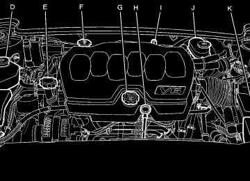
Passenger Compartment Air Filter Outside air is routed through a passenger compartment air filter before entering the vehicle. This filter removes certain particles from the air, including pollen and dust particles. The filter should be replaced as part of routine scheduled maintenance. See Scheduled Maintenance on page 7‑3 for when to replace the filter. The access panel for the passenger compartment air filter is located under the hood near the windshield, on the passenger's side of the vehicle.
To access the passenger compartment air filter, do the following:
1. Press the tabs back and left to remove the cover.
2.
Insert a tool behind the push pin located on the inboard side of the air filter compartment to carefully pry the pin out.
4-28
3. To remove the air filter, insert a tool between the
air filter and the compartment wall on the outboard side of the vehicle. Then, push in to flatten the pin holding the air filter in place. Gently remove the air filter and any loose debris that may be inside the air filter compartment.
4.
Insert the new air filter by pushing until you hear a click. Reinstall the push pin and snap the cover into place.
4-29
Warning Lights, Gauges, and Indicators Warning lights and gauges can signal that something is wrong before it becomes serious enough to cause an expensive repair or replacement. Paying attention to the warning lights and gauges could prevent injury. Warning lights come on when there might be or there is a problem with one of the vehicle's functions. Some warning lights come on briefly when the engine is started to indicate they are working. Gauges can indicate when there might be or there is a problem with one of the vehicle's functions. Often gauges and warning lights work together to indicate a problem with the vehicle.
When one of the warning lights comes on and stays on while driving, or when one of the gauges shows there could be a problem, check the section that explains what to do. Follow this manual's advice. Waiting to do repairs can be costly and even dangerous. Instrument Panel Cluster The instrument panel cluster is designed to show how the vehicle is running. It shows how fast the vehicle is going, how much fuel has been used, and many other things needed to drive safely and economically. The vehicle has this cluster or one very similar to it. It includes indicator warning lights and gauges that are explained on the following pages. Be sure to read about them.
4-30
United States Super Model Shown, Canada and Base Similar
4-31
Speedometer and Odometer The speedometer shows the vehicle speed in both miles per hour (mph) and kilometers per hour (km/h). The odometer shows how far the vehicle has been driven, in either miles or kilometers. This vehicle has a tamper resistant odometer. If the vehicle needs a new odometer installed, the new one can be set to the mileage total of the old odometer. If this is not possible, it is set to zero and a label must be put on the driver's door to show the old mileage reading when the new odometer was installed. Trip Odometer A trip odometer show how far the vehicle has been driven since the odometer was last set to zero. See Driver Information Center (DIC) on page 4‑47 for information on resetting the trip odometer.
Tachometer The tachometer displays the engine speed in revolutions per minute (rpm). Safety Belt Reminders Safety Belt Reminder Light When the engine is started, a chime sounds for several seconds to remind a driver to fasten the safety belt, unless the driver safety belt is already buckled.
The safety belt light comes on and stays on for several seconds, then flashes for several more.
This chime and light are repeated if the driver remains unbuckled and the vehicle is in motion. If the driver safety belt is already buckled, neither the chime nor the light comes on.
4-32
Airbag Readiness Light The system checks the airbag's electrical system for possible malfunctions. If the light stays on it indicates there is an electrical problem. The system check includes the airbag sensor, the pretensioners, the airbag modules, the wiring and the crash sensing and diagnostic module. For more information on the airbag system, see Airbag System on page 2‑56.
The airbag readiness light flashes for a few seconds when the engine is started. If the light does not come on then, have it fixed immediately.
{ WARNING:
If the airbag readiness light stays on after the vehicle is started or comes on while driving, it means the airbag system might not be working properly. The airbags in the vehicle might not inflate in a crash, or they could even inflate without a crash. To help avoid injury, have the vehicle serviced right away.
If there is a problem with the airbag system, an airbag Driver Information Center (DIC) message can also come on. See DIC Warnings and Messages on page 4‑55 for more information.
4-33
Passenger Airbag Status Indicator The vehicle has the passenger sensing system. See Passenger Sensing System on page 2‑67 for important safety information. The overhead console has a passenger airbag status indicator.
United States
Canada
When the vehicle is started, the passenger airbag status indicator will light ON and OFF, or the symbol for on and off, for several seconds as a system check.
If you are using remote start to start the vehicle from a distance, if equipped, you may not see the system check. Then, after several more seconds, the status indicator will light either ON or OFF, or either the on or off symbol, to let you know the status of the right front passenger frontal and seat-mounted side impact airbags. If the word ON or the on symbol is lit on the passenger airbag status indicator, it means that the right front passenger frontal airbag and seat-mounted side impact airbag are enabled (may inflate). If the word OFF or the off symbol is lit on the passenger airbag status indicator, it means that the passenger sensing system has turned off the right front passenger frontal and seat‐mounted side impact airbag.
4-34
If, after several seconds, both status indicator lights remain on, or if there are no lights at all, there may be a problem with the lights or the passenger sensing system. See your dealer for service.
{ WARNING:
If the airbag readiness light ever comes on and stays on, it means that something may be wrong with the airbag system. To help avoid injury to yourself or others, have the vehicle serviced right away. See Airbag Readiness Light on page 4‑33
for more information, including important safety information.Charging System Light
This light comes on briefly when the ignition key is turned to START, but the engine is not running, as a check to show it is working.
If it does not, have the vehicle serviced by your dealer. The light should go out once the engine starts. If it stays on, or comes on while driving, there could be a problem with the charging system. A charging system message in the Driver Information Center (DIC) can also appear. See DIC Warnings and Messages on page 4‑55 for more information. This light could indicate that there are problems with a generator drive belt, or that there is an electrical problem. Have it checked right away. If the vehicle must be driven a short distance with the light on, turn off accessories, such as the radio and air conditioner.
4-35
Brake System Warning Light The vehicle's hydraulic brake system is divided into two parts. If one part is not working, the other part can still work and stop the vehicle. For good braking both parts need to be working. If the warning light comes on, there is a brake problem. Have the brake system inspected right away.
When the ignition is on, the brake system warning light also comes on when the parking brake is set. The light will stay on if the parking brake does not fully release. If it stays on after the parking brake is fully released, it means there is a brake problem.
{ WARNING:
The brake system might not be working properly if the brake system warning light is on. Driving with the brake system warning light on can lead to a crash. If the light is still on after the vehicle has been pulled off the road and carefully stopped, have the vehicle towed for service.
United States
Canada
This light should come on briefly when the engine is started. If it does not come on then, have it fixed so it will be ready to warn if there is a problem.
If the light comes on while driving, pull off the road and stop carefully. The pedal can be harder to push, or the pedal could go closer to the floor. It could take longer to stop. Try turning off and restarting the vehicle one or two times, if the light is still on, have the vehicle towed for service. See Towing Your Vehicle on page 5‑24.
4-36
Antilock Brake System (ABS) Warning Light
For vehicles with the Antilock Brake System (ABS), this light comes on briefly when the engine is started.
If it does not, have the vehicle serviced by your dealer. If the system is working normally the indicator light then goes off.
If the ABS light stays on, turn the ignition off. If the light comes on while driving, stop as soon as it is safely possible and turn the ignition off. Then start the engine again to reset the system. If the ABS light stays on, or comes on again while driving, the vehicle needs service. If the regular brake system warning light is not on, the vehicle still has brakes, but not antilock brakes. If the regular brake system warning light is also on, the vehicle does not have antilock brakes and there is a problem with the regular brakes. See Brake System Warning Light on page 4‑36. For vehicles with a Driver Information Center (DIC), see DIC Warnings and Messages on page 4‑55 for all brake related DIC messages.
4-37
Traction Control System (TCS) Warning Light
For vehicles with a Traction Control System (TCS) and StabiliTrak® warning light, this light comes on briefly when the engine is started.
If it does not, have the vehicle serviced by your dealer. If the system is working normally the indicator light then goes off.
When the system is active, the light flashes while the system is limiting wheel spin or assisting with controlling the vehicle. If it stays on or comes on while driving a SERVICE TRACTION CONTROL message appears in the Driver Information Center (DIC). This indicates that there could be a problem with the traction control system and the vehicle may need service. When this warning light is on and the SERVICE TRACTION CONTROL message appears on the DIC, the system does not limit wheel spin. If the traction control system is manually turned off, this light comes on and the TRACTION CONTROL OFF message appears on the DIC. See Traction Control System (TCS) on page 5‑6 and DIC Warnings and Messages on page 4‑55 for more information.
4-38
StabiliTrak® Indicator Light
This light comes on briefly while starting the engine.
See StabiliTrak® System on page 5‑6 and DIC Warnings and Messages on page 4‑55 for more information. Lane Departure Warning (LDW) Light
For vehicles with the lane departure warning system, this light briefly comes on green while starting the vehicle.
If it does not, have the vehicle serviced by your dealer. If the system is working normally the indicator light will then go off. This light may come on while the vehicle is first driven and the STABILITRAK NOT READY message will appear in the Driver Information Center (DIC). See StabiliTrak® System on page 5‑6 for more information. If the light stays on, or comes on while driving a SERVICE STABILITRAK message will appear in the DIC. This indicates that there may be a problem with the StabiliTrak® system and the vehicle may need service. When this warning light is on and the SERVICE STABILITRAK message appears on the DIC, the system will not assist with controlling the vehicle. When the system is active, the light will flash while the system is assisting with controlling the vehicle.
If it does not, have the vehicle serviced by your dealer. If the system is working normally the indicator light then goes off. This light also comes on green if the system detects a left or right lane marking. It flashes, changes to amber, and three beeps sound, if a detected lane marking is crossed without using a turn signal. For more information, see the Index in the Navigation Manual.
4-39
Engine Coolant Temperature Warning Light
Engine Coolant Temperature Gauge
This light comes on briefly while starting the vehicle.
If it does not, have the vehicle serviced by the dealer. If the system is working normally the indicator light goes off. Notice: Driving with the engine coolant temperature warning light on could cause the vehicle to overheat. See Engine Overheating on page 6‑35. The vehicle's engine could be damaged, and it might not be covered by the vehicle warranty. Never drive with the engine coolant temperature warning light on. The engine coolant temperature warning light comes on when the engine has overheated. If this happens pull over and turn off the engine as soon as possible. See Engine Overheating on page 6‑35 for more information.
4-40
United States
Canada
This gauge shows the engine coolant temperature. If the pointer moves towards the H (United States) or shaded in thermostat symbol area (Canada), the engine is too hot. A temperature indicator light will turn on and a chime will sound. If the vehicle has been operating under normal driving conditions, and the temperature indicator light comes on, pull off the road, stop the vehicle and turn off the engine as soon as possible.
Tire Pressure Light
For vehicles with a tire pressure monitoring system, this light comes on briefly when the engine is started. It provides information about tire pressures and the Tire Pressure Monitoring System. When the Light is On Steady This indicates that one or more of the tires is significantly underinflated. A tire pressure message in the Driver Information Center (DIC), can accompany the light. See Driver Information Center (DIC) on page 4‑47 for more information. Stop and check the tires as soon as it is safe to do so. If underinflated, inflate to the proper pressure. See Inflation - Tire Pressure on page 6‑65
for more information.When the Light Flashes First and Then is On Steady This indicates that there may be a problem with the Tire Pressure Monitor System. The light flashes for about a minute and stays on steady for the remainder of the ignition cycle. This sequence repeats with every ignition cycle. See Tire Pressure Monitor Operation on page 6‑67 for more information. Malfunction Indicator Lamp Check Engine Light A computer system called OBD II (On-Board Diagnostics-Second Generation) monitors operation of the fuel, ignition, and emission control systems. It ensures that emissions are at acceptable levels for the life of the vehicle, helping to produce a cleaner environment.
This light should come on when the ignition is on, but the engine is not running, as a check to show it is working. If it does not, have the vehicle serviced by your dealer.
4-41
This light comes on during a malfunction in one of two ways: Light Flashing: A misfire condition has been detected. A misfire increases vehicle emissions and could damage the emission control system on the vehicle. Diagnosis and service might be required. To prevent more serious damage to the vehicle:
. Reduce vehicle speed. . Avoid hard accelerations. . Avoid steep uphill grades.
If towing a trailer, reduce the amount of cargo being hauled as soon as it is possible.
If the light continues to flash, when it is safe to do so, stop the vehicle. Find a safe place to park the vehicle. Turn the key off, wait at least 10 seconds, and restart the engine. If the light is still flashing, follow the previous steps and see your dealer for service as soon as possible.
If the check engine light comes on and stays on, while the engine is running, this indicates that there is an OBD II problem and service is required. Malfunctions often are indicated by the system before any problem is apparent. Being aware of the light can prevent more serious damage to the vehicle. This system assists the service technician in correctly diagnosing any malfunction. Notice: If the vehicle is continually driven with this light on, after a while, the emission controls might not work as well, the vehicle's fuel economy might not be as good, and the engine might not run as smoothly. This could lead to costly repairs that might not be covered by the vehicle warranty. Notice: Modifications made to the engine, transmission, exhaust, intake, or fuel system of the vehicle or the replacement of the original tires with other than those of the same Tire Performance Criteria (TPC) can affect the vehicle's emission controls and can cause this light to come on. Modifications to these systems could lead to costly repairs not covered by the vehicle warranty. This could also result in a failure to pass a required Emission Inspection/Maintenance test. See Accessories and Modifications on page 6‑3.
4-42
Light On Steady: An emission control system malfunction has been detected on the vehicle. Diagnosis and service might be required. An emission system malfunction might be corrected by doing the following:
. Make sure the fuel cap is fully installed. See Filling
the Tank on page 6‑10 . The diagnostic system can determine if the fuel cap has been left off or improperly installed. A loose or missing fuel cap allows fuel to evaporate into the atmosphere. A few driving trips with the cap properly installed should turn the light off. If the vehicle has been driven through a deep puddle of water, the vehicle's electrical system might be wet. The condition is usually corrected when the electrical system dries out. A few driving trips should turn the light off.
. Make sure to fuel the vehicle with quality fuel. Poor fuel quality causes the engine not to run as efficiently as designed and can cause: stalling after start-up, stalling when the vehicle is changed into gear, misfiring, hesitation on acceleration, or stumbling on acceleration. These conditions might go away once the engine is warmed up. If one or more of these conditions occurs, change the fuel brand used. It will require at least one full tank of the proper fuel to turn the light off. See Gasoline Octane on page 6‑6.
If none of the above have made the light turn off, your dealer can check the vehicle. The dealer has the proper test equipment and diagnostic tools to fix any mechanical or electrical problems that might have developed.
4-43
Emissions Inspection and Maintenance Programs Some state/provincial and local governments have or might begin programs to inspect the emission control equipment on the vehicle. Failure to pass this inspection could prevent getting a vehicle registration. Here are some things to know to help the vehicle pass an inspection: