- Download PDF Manual
-
158nLamps and bulbs
Footwell lamps 5 watt bulb 1 Pry the lamp out using a screwdriver 2 Replace the bulb.
Glove compartment lamp 5 watt bulb 1 Pry the lamp out using a screwdriver 2 Replace the bulb.
Luggage compartment lamps One lamp each in the bulb holder of the tail lamp assembly: 10 watt bulb. 1 Apply a screwdriver to the recess and
remove the lens
2 Replace the bulb.
In the rear (only with the hardtop*) Interior lamps (6 watt bulb) Reading lamp (6 watt bulb) 1 Pry the lamp out using a screwdriver 2 Turn the bulb holder to the left and
remove it
3 Remove and replace the bulb.
Do not lie under the vehicle or start the engine when the vehicle is supported by the jack. Failure to comply with this cre- ates a risk of fatal injury.<
Your BMW has a space-saver spare tire for temporary use to ensure your mobility.
To remove the space-saver spare tire, lift the floor panel in the lug-
gage compartment completely out (refer to page 41).<
Changing a wheel
Safety measures in the event of a flat tire or wheel change:
Stop the vehicle as far as possible from passing traffic. Park on a firm, flat sur- face. Switch on the hazard flashers. Turn the steering wheel to the straight- ahead position, remove the key and en- gage the steering lock. Shift into 1st or reverse (selector lever in "Park" with au- tomatic transmission) and engage the parking brake. Have all passengers leave the vehicle and remain well away from your immedi- ate working area (behind a guardrail, for instance). If a warning triangle* or portable hazard warning lamp is available, set it up on the roadside at an appropriate distance from the rear of the vehicle. Comply with all safety guidelines and regulations. Change the wheel only on a level, firm surface that is not slippery. Avoid jack- ing the vehicle on a soft or slippery sup- port surface (snow, ice, loose gravel, etc.), as it could slide sideways. Position the jack on a firm support sur- face. Do not place wooden blocks or similar objects under the jack, otherwise, the jack might not be able to reach its full support capacity because of the limited height.
159n
What you will need In order to avoid rattling noises later, note the position of the tools when you remove them and return them to their original position when you are through using them. > Jack (1)
Raise the floor panel in the luggage compartment (refer to page 41) and unscrew the red wing nut (arrow). When you have completed your work, screw the jack all the way back down. Fold the handle back and insert it into its holder > Wedge (2)
The wedge, or wheel chock, is lo- cated behind the jack on the luggage compartment's rear wall. Loosen the wing nut to remove it
160nChanging a wheel
> Space-saver spare tire
Located next to the jack. Loosen the wing nut (arrow) by hand, remove the storage tray and take out the spare wheel
> Lug wrench – is in the onboard tool kit on the underside of the luggage compartment lid (refer to page 152).
Procedure 1 Read and comply with the safety
precautions provided on the previ- ous page
2 Secure the vehicle against rolling: Place the wedge against the rear surface of the front tire on the side opposite the side being raised. If the vehicle is parked on a down- ward slope, place the wedge se- curely in front of the tire. If the wheel must be changed on a sur- face with a more severe slope, take additional precautions to secure the vehicle against rolling
3 If your wheels are equipped with full wheel covers*, reach into the venti- lation openings and pull the cover off
4 Loosen the lug bolts 1/2 turn 5 Position the jack at the jacking point
closest to the flat tire (refer to the center illustration) so that the jack base is vertically below the jacking point and the entire surface of the head of the jack will move into the square recess of the jacking point (refer to the illustration detail) when the jack is cranked
6 Jack the vehicle up until the wheel you are changing is raised from the ground
7 Unscrew the lug bolts and remove
the wheel
8 Remove mud or dirt accumulations from the mounting surfaces of the wheel and hub. Clean the lug bolts
Changing a wheel
161n
9 Position the new wheel or the
space-saver spare tire on the hub and screw at least two lug bolts fin- ger-tight into opposite bolt holes 10 Screw in the remaining lug bolts.
Tighten all the bolts snugly
13 If your wheels are equipped with full
wheel covers*, place the wheel cover with the valve opening over the valve (arrow). Use both hands to press the cover securely onto the rim
11 Lower the jack and remove it from
14 Check and correct the tire's inflation
beneath the vehicle
12 Tighten the lug bolts in a diagonal
pattern
pressure at the earliest possibility. For vehicles with RDC (Tire Pres- sure Control)*: After mounting the space-saver spare tire or correcting the inflation pressure, reactivate the system. Refer to page 89.
Only use original BMW full wheel covers, otherwise, the trim piece
may not fit securely. The full wheel cover may not be installed on the space-saver spare tire, since this could damage the cover.<
The vehicle jack is designed for changing wheels only. Do not at- tempt to raise another vehicle model with it or to raise any load of any kind. To do so could cause accidents and personal injury. To ensure continued safety, have the solid fit of the lug bolts [torque: 72 lbft (100 Nm)] checked using a calibrated torque wrench.<
When storing the wheel, take care to ensure that you do not damage the retaining pin in the spare tire recess. If light-alloy wheels other than original BMW light-alloy wheels have been mounted, it may be necessary to use different lug bolts for those wheels. Replace the defective tire as soon as possible and have the new wheel/tire balanced.
162nChanging a wheel
Battery
Driving with the space-saver spare tire Drive cautiously. Do not exceed a speed of 45 mph (80 km/h). You can anticipate changes in vehicle handling such as delayed braking re- sponse, longer braking distances and changes in self-steering properties when approaching stability limits. The changes in handling characteristics will be even more pronounced in con- junction with winter tires.
Only one space-saver spare tire may be mounted at one time. Re- install wheels and tires of the same size and specification as soon as possible. Maintain correct tire pressures. Refer to page 28.<
Installation location The battery is located at the right-rear of the luggage compartment. Raise the luggage compartment floor panel (refer to page 40). Release the two fasteners plus an additional fastener in the upper- center side trim panel by turning a screwdriver or a coin 1/4-turn counter- clockwise. In order to remove the stor- age tray, slide the side trim panel slightly upward.
Charge condition You can read the charge condition of the battery with the "Magic Eye"* (= hydrometer): > Green: adequate charge > Black: not adequately charged. The battery must be recharged. Please contact your BMW center for addi- tional information
> Yellow: replace the battery.
The service life specified for the battery can be achieved only if it is always kept adequately charged. If the vehicle is primarily used for driving short distances, be sure to check the charge status often.<
Battery
Battery care The battery is absolutely maintenance- free, that is, the original acid will nor- mally last for the service life of the battery under temperate climatic conditions.
For all questions regarding the battery, please consult your BMW
center. Since the battery is absolutely maintenance-free, the following infor- mation is for your use only.<
Symbols You will find the following symbols on your vehicle battery. For your safety, please be cautious whenever you work with or near the battery.
Before handling the battery, please read the following infor- mation. Wear eye protection. Do not al- low particles containing battery acid or lead to come into con- tact with your eyes, your skin, or your clothing.
Battery acid is extremely corro- sive. Wear eye protection and protective gloves. Do not tip the battery. Battery acid can leak from the ventilation openings.
Do not allow children to have access to batteries and battery acid. Never allow sparks or open flame near the battery. Do not smoke in the vicinity of the bat- tery. Avoid sparks from electrical cables or electrical equipment. Turn the key to position 0 in the steering lock when dis- connecting or connecting the battery. Do not short-circuit the battery termi- nals. This creates a risk of injury from high-energy sparks.
163n
A highly explosive gas is generated when the battery is charged. If you happen to get acid in your eyes, rinse thoroughly for 15 minutes with clear water.
Consult a physician immediately. If you get acid spray on your skin or clothing, rinse with plenty of water. If acid is ac- cidentally ingested, consult a physician immediately.
In order to protect the battery case from ultraviolet radiation, do not place it in direct sunlight. A drained battery can freeze. Store the battery in areas where temperature remains above freezing.
164nBattery
Removal and installation
Do not disconnect the battery when the engine is running. If you do so,
the ensuing voltage surge will damage the vehicle's onboard electronics. Do not make any modifications in the wires to the positive terminal. If you do so, the protective function of the safety battery terminal is no longer ensured. Repair and disposal must be performed by trained technicians only.<
When removing the battery, disconnect the cable on the negative terminal first, then the cable on the positive terminal. Loosen the center adjusting screw on the battery retaining strap (use the screwdriver included with the onboard tool kit) and disconnect the strap. When installing a battery, connect the positive terminal first, then connect the negative terminal.
When installing a battery, be sure that it is mounted properly and that the retaining bracket is installed with the center adjustment screw, otherwise, the battery will not be adequately secured in case of an accident.<
Charging the battery Charge the battery in the vehicle only when the engine is not running.
Before performing any work on the electrical system, be sure to unclamp the cable from the battery's negative terminal. Failure to do so can result in short-circuits, a fire or per- sonal injury.<
If you plan to park the vehicle for longer than 4 weeks, disconnect the battery from the vehicle's electrical system by disconnecting the cable at the negative terminal. Then recharge the battery with an appropriate battery charger. If you intend to store the vehicle for longer than 12 weeks, remove the bat- tery, charge it and store it in a cool and dust-free room where there is no dan- ger of freezing. During storage, have the battery recharged every 3 months. Also, recharge the battery before it is reinstalled. If this is not done, the bat- tery will not be serviceable. Every time the battery is drained, especially over extended periods, its service life is reduced.
Return used batteries to a recy- cling point or your BMW center. Maintain the battery in an upright posi- tion for transport and storage. Secure the battery to prevent it from tilting during transport.<
Storage periods during which the battery is disconnected are
not taken into consideration by the Service Interval Display for changing the brake fluid. For this reason, be sure that the brake fluid is changed every two years, re- gardless of the information displayed. Read and comply with the information on page 136 covering this subject.<
Fuel filler door
165n
A list of fuses, their respective ampere ratings and the equipment in their cir- cuits are all indicated below the fuse holder. To close the fuse holder, snap it into position at the top and turn the two fasteners inward.
Do not attempt to repair a burned- out fuse or replace it with a fuse with a different color or ampere rating. Doing this could cause a fire in the ve- hicle resulting from a circuit overload.<
If a fuse blows repeatedly, refer the problem to your BMW center for repair.
Manual release Pull the knob with the fuel pump symbol (arrow) on the right trim panel of the luggage compartment.
Fuses
If an electrical accessory should fail, switch it off and check the fuse.
In the glove compartment 1 Open the glove compartment and
turn the two white quick-release fasteners outward. Spare fuses and plastic tweezers are located on the fuse holder
2 Use the plastic tweezers to remove the fuse for the accessory or equip- ment that has stopped working
3 Replace a burned-out fuse, recogniz- able from the melted metal strip, with a new fuse of the same color code or ampere rating.
166nFully automatic convertible top*
Closing manually in the event of an electrical malfunction
Closing the convertible top manu- ally is best done from the outside
with the driver's door open and the driver's seat tilted forward. The rear seat should not be occupied while this operation is taking place.c
1 Remove the filler piece from between the rear seats. Remove the trim from the guide rod and tilt it forward. Press forcefully on the emergency lock op- eration (arrow). Doing this will unlock the mechanisms for the convertible top compartment lid after a short delay
2 With the luggage compartment lid
4 Using a screwdriver, lift out the cover
closed, open the convertible top compartment lid all the way
panel in the center of the front con- vertible top frame
3 Take hold of the convertible top by its
5 Put the dual-end Allen wrench
lateral guide section and its front convertible top frame and lift it out (arrow). Position the rear convertible top bar vertically and close the con- vertible top compartment lid. Flip the rear convertible top bar downward
(stored next to the emergency lock, see left column) into the hex slot (arrow)
6 Pull the front convertible top frame downward as far as possible. Con- tinue the closing process by turning the Allen wrench to the left; keep on turning until the front convertible top frame is locked onto the windshield frame. The rear convertible top frame will be automatically pressed onto the convertible top compartment lid, and because of the pressure, will be sealed off when closed.
Fully automatic convertible top*
167n
Please refer to your BMW center to have the defect corrected.c
In the event of an electrical defect, never open the convertible top by hand. The convertible top compartment lid cannot be locked and would open while driving.c
168n
Jump-starting
Do not use spray starter fluids to start the engine. If the battery is drained, the engine can be started using two jumper cables and another vehicle's battery. Use only jumper cables with fully insulated handles on the terminal clamps.
Do not touch the parts conducting electrical current while the engine
is running. Failure to comply with this creates a risk of fatal injury.<
Carefully comply with the following in- structions to avoid personal injury or damage to one or both vehicles: 1 Be sure that the battery on the sup- port vehicle is also rated at 12 volts, and that the capacities of the two batteries (Ah) are roughly comparable (printed on casing)
2 Leave the drained battery connected
to the vehicle's electrical system
3 Make sure that there is no contact between the bodywork of the two vehicles – short circuit risk!
4 Start by connecting the jumper cable from the positive terminal of the sup- port vehicle to the positive terminal connector located in your BMW's engine compartment. The cover of the auxiliary terminal for jump-start-
ing is identified by a "+" sign. Refer to the illustration. Remove by pulling the tab (arrow 1)
5 Then connect the negative terminals. Attach the cable to either the support vehicle's negative battery terminal (–), or to a suitable ground on its engine or bodywork. Then connect the other end of the cable to a ground on the engine or on the bodywork of the ve- hicle that is to be started. There is a special nut provided for this on the BMW (arrow 2)
Follow the same sequence for connecting the jumper cables
when helping other vehicles. If you do not, there is the risk of injury if sparks are generated at the battery.<
6 Start the support vehicle's engine
and let it run
7 Start the engine on the vehicle need- ing the jump-start, and allow it to run as usual. If the first start attempt is not successful, wait a few minutes before another attempt in order to allow the drained battery to recharge
8 Before disconnecting the jumper
cables from your BMW, turn on the rear window defroster and set the blower to the highest speed; allow the engine to run approx. 10 seconds. This will prevent a voltage surge from the voltage regulator to the electrical accessories
9 Then disconnect the jumper cables in
reverse sequence.
Depending on the reason for the mal- function, recharge the battery.
Towing the vehicle
169n
Tow fitting The screw-in tow fitting is stored in the onboard tool kit; be sure that it remains in the vehicle at all times. This fitting is designed for installation in the tow sockets located at the front and rear of the vehicle. It is intended for towing on paved road surfaces only. This fitting should not be used to pull a vehicle out of deep snow, mud, sand, etc. Always comply with all applicable towing laws and regulations.
Access to tow sockets Front: Using a screwdriver, press out the cover panel on the top part of the recess.
Rear: Using a screwdriver, press out the cover panel on the top part of the recess.
Screw the tow fittings in com- pletely and tightly. If you do not,
the threads could be damaged. Do not tow the vehicle by any compo- nents of the running gear, or lash them down in any way. If you do, the compo- nents could be damaged, leading to possible accidents.<
Towing with a commercial tow truck > Do not tow with sling-type equipment > Use wheel lift or flat bed equipment > Please comply with applicable state
towing laws.
Never allow passengers to ride in a towed vehicle for any reason.
Never attach tie-down hooks, chains, straps, or tow hooks to the tie rods, control arms, or any other part of the vehicle suspension. If you do so, severe damage will occur to these compon- ents.c
170n
Adaptive Transmission Control
(ATC) 172
Airbags 173
Dynamic Stability Control(DSC) 173
Radio reception 174
Safety belt tensioner 174
Interior rearview mirror withautomatic dimmer 175
Rain sensor 176
Tire Pressure Control (RDC) 177
Self-diagnostics 178
Rollover protection system 179
Xenon lamps 179171n
Overview
Controls and features
Operation, care and maintenance
Owner service procedures
Advanced technology
Technical data
Index
Technology
In order to include driving conditions in its calculations, ATC registers curves and both uphill and downhill gradients. For example, if you maintain speed through a curve, the transmission does not shift up. On uphill gradients, it shifts up only when the engine speed increases in order to make more efficient use of power reserves. On downhill gradients, ATC shifts down when the speed of the vehicle increases and the driver must apply the brakes.
172n
ATC*
For vehicles with automatic transmis- sion*, Adaptive Transmission Control (ATC) makes the optimum gear selec- tion based on a number of factors. In this process, it considers your individ- ual driving style as well as current driving conditions. ATC recognizes your personal driving style from the positions and movements of the accelerator pedal, deceleration when braking, and lateral acceleration through curves. ATC makes the appro- priate selection based on various shift characteristics, which range from com- fort- to performance-oriented.
Airbags
DSC
173n
Deceleration sensors continuously monitor the acceleration forces acting upon the vehicle. If, as the result of a frontal collision, a deceleration is reached at which the protection of the safety belts alone is no longer ade- quate, the gas generators of the driver and passenger-front airbags are ignited. However, the passenger-side airbag is only triggered if an additional sensor has recognized that the passenger seat is occupied. In the event of a side collision, the side airbags in the front are triggered if necessary.
The airbags located under the marked covers inflate and unfold in a matter of a few milliseconds. In this process, they tear through the designed separation points of the upholstered covers or press them out. Because the inflation process must be virtually instantaneous, it is necessarily accompanied by a certain amount of ignition and inflation noise. The gas required to inflate the airbags is not dangerous, and the smoke associated with it dissipates. The entire process is completed within fractions of a second.
Highly sensitive sensors monitor the wheel speeds, steering angle, lateral acceleration, brake pressure and the movement of the vehicle around its vertical axis. If differences in the wheel speeds occur, the system counteracts the danger of wheelspin by reducing torque. If neces- sary, the system also responds with additional brake applications at the rear wheels. In addition, DSC permanently monitors the vehicle's current operating condition and compares it with an ideal condition that is calculated from the sensor sig- nals. If deviations from this occur (un- dersteering or oversteering, for in- stance), DSC can stabilize the vehicle in fractions of a second by reducing engine output and with the assistance of brak- ing intervention at individual wheels. As a result, most skids can be preven- ted from their very onset. You may need some time to become accustomed to this system intervention. However, it provides optimum drive force and vehicle stability. The braking intervention may be accompanied by sounds specific to the system.
174nRadio reception
Safety belt tensioner
The limitations inherent to radio recep- tion in a moving vehicle have been min- imized by a number of innovative sys- tem designs: The "Radio Data System" (RDS) makes sure that, for stations broadcasting on several frequencies, the radio automati- cally tunes to the frequency with the best reception quality. With the Diversity Antenna system, sev- eral FM antennas are integrated within the convertible top compartment lid to provide three separate sources for re- ceiving broadcast waves. An integral processor automatically selects the an- tenna with the best FM reception qual- ity at any given time. The selection of the antenna takes place within millisec- onds, and is therefore not noticed by the radio listener.
The safety belt tensioners respond to severe head-on collisions by tightening the belts to ensure that occupants remain firmly positioned in their seats. A gas-pressure system retracts the buckle assembly to tension the shoul- der and lap belts within fractions of a second. This reduces the tendency to slide under the lap belt.
The AM frequency bands (medium- wave, long-wave and short-wave) make it possible to receive stations from a great distance, because the broadcast signals travel not only along the ground as surface waves, but also as atmospheric waves that are re- flected from the ionosphere. Frequency-modulation (FM) provides substantially better sound quality than the other frequencies. However, because FM transmissions rely on line- of-sight broadcast waves, their effec- tive reception range is limited.
Interior rearview mirror with automatic dimmer*
175n
The semisolid reacts chemically to this electrical current, dimming the mirror through an infinitely-variable range (electrochromic technology). As a result, it is no longer necessary to dim the mirror manually, and the driver can concentrate completely on traffic conditions.
The interior rearview mirror with auto- matic dimming feature reduces glare by adapting the intensity of the reflected images to correspond to levels of light registered by the unit's sensors. The mirror reverts to its undimmed setting as soon as the light source disappears. One light sensor is mounted on the front of the mirror housing. This sensor, the one that is directed forward, measures light intensity in the area ahead of the vehicle. The second sensor is inte- grated within the mirror's glass. The electronic control system compares the light intensity from front and rear. The difference provides the basic parameter used to modulate an electrical current and induce chemical changes in a semi- solid layer incorporated in the lens.
176nRain sensor*
When the system is set to the "Intermit- tent" wiper speed, the wipers react im- mediately – if water is splashed onto the windshield by vehicles traveling ahead of you, for example. As a result, the rain sensor contributes to driving safety and comfort.
Depending on how wet the windshield is, the rain sensor controls the opera- tion of the windshield wipers. Infrared light is carried along the sur- face of the windshield in an optical con- ductor in such a manner that it is re- flected completely when the windshield is dry. The quantity of reflected light is measured. If there is moisture on the glass, the amount of light reflected is reduced since the infrared light at the surface of the windshield can escape. The quan- tity of reflected light is thus a means of gauging the degree of wetness on the windshield.
Tire Pressure Control (RDC)*
177n
There is an antenna located right near every wheel in the vehicle body. Each antenna picks up signals from its re- spective wheel. A central electronics system evaluates all four signals and forwards any changes. The RDC pro- vides an important contribution to driving safety.
This system regularly checks tire pres- sure and monitors all four tires even while driving, so you don't have to. Behind the valve stem in every wheel, there is an electronic chip that is de- signed for severe-duty applications and long service life. It contains a pressure sensor, a transmitter and a battery. The pressure is measured in extremely short time intervals and then transmitted by a radio signal. If an irregularity is detected, the transmis- sion rate is increased.
The sounds the automatic climate con- trol makes as it carries out its self-diag- nostics are noticeable because of the noise that the ventilation flaps make af- ter the ignition has been switched off. All of the other self-diagnostics func- tions operate silently in the back- ground. Any possible defects detected during these self-diagnostics can be read out by your BMW center and quickly cor- rected during the vehicle's next regu- larly scheduled maintenance.
178nSelf-diagnostics
All of the important electrical and elec- tronic systems in the vehicle are tested regularly and automatically; the driver does not have to perform any extra operations or adjustments. The indicator lamps come on briefly when the ignition is switched on. While you are driving, the functional status of the actuator motors (for the windshield wipers, power windows, seats, etc.) is constantly analyzed by current measurements in their relays.
In the same manner, the electrical re- sistance of the airbag ignition genera- tors and all of the remaining airbag components is measured at all times. Any fault in this system would be de- tected immediately by a current fluctua- tion that would necessarily accompany it. The fault would be indicated immedi- ately by the airbag warning lamp. Even after you shut off the engine, the overall functional status of your vehicle is being monitored. For example, all of the flaps for the heating and ventilation system travel to the nearest limit posi- tion. This action ensures that in any case, the defrosting function will remain intact, even if a malfunction in the auto- matic climate control should occur dur- ing the night while the vehicle is parked. A calibration cycle runs every tenth time the engine is shut off. During this cycle, the actuator motors of all the heating and ventilation flaps travel to their limit stops in both directions. The limit posi- tions and the return travel paths are checked in this manner in order to en- sure that appropriate adjustments for the operating elements can be made at any time.
Rollover protection system Xenon lamps*
179n
The rollover protection system offers additional protection apart from the air- bags and safety belts. The system has highly sensitive sensors that react im- mediately upon detecting an unstable vehicle condition, i.e. when the vehicle is tilted to a critical degree, or if the wheels are not making proper ground contact. In this kind of situation, the protective bar in each rear head restraint is triggered.
Xenon lamps illuminate the side and front areas of the vehicle with signifi- cantly more brightness and uniformity than the traditional halogen lamp. In a xenon lamp, an electric arc re- places the filament in order to generate intense illumination. A gas mixture in a quartz glass tube with metal vapor is ignited by a high electric voltage. The arc that is generated is then sustained by a lower voltage. When the lamp is turned on there is a brief warm-up period. Maximum brightness is attained in approx. 15 seconds.
Xenon lamps provide significantly im- proved visibility, especially during ad- verse weather and poor driving condi- tions e.g. driving at night in heavy rain or through road repair areas where there are no lane markers. Vehicles with xenon lamps are equipped with automatic headlamp range control. As a result, the highway is always opti- mally lighted, regardless of road condi- tions, and drivers in oncoming traffic are not blinded. Xenon lamps make a significant contri- bution to highway safety since pedestri- ans and other highway users, bicyclists and motorcyclists in the right lane, are more easily detected.
180n
Engine data 182
Dimensions 183
Weights 184
Capacities 185
Electrical system 186
Drive belts 186181n
Overview
Controls and features
Operation, care and maintenance
Owner service procedures
Advanced technology
Technical data
Index
Data
182n
Engine data
Displacement Number of cylinders Maximum output at engine speed Maximum torque at engine speed Compression ratio Stroke Bore Fuel-injection system
cu. in. (cmm)
hp (kW) rpm lb.ft (Nm) rpm in (mm) in (mm)
BMW 323Ci 152.2 (2,494) 170 (127) 5,500
181 (245) 3,500
10.5
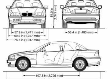
2.95 (75) 3.31 (84) Digital electronic engine-management systemDimensions
183n
Minimum turning circle dia.: 34.4 feet (10.5 m).
184nWeights
BMW 323Ci
lbs. (kg) lbs. (kg)
3,560 (1,615) 3,627 (1,645)
Curb weight (with one person, ready for operation, full tank of fuel, options not included) with manual transmission with automatic transmission* Approved gross vehicle weight with manual transmission with automatic transmission* Approved front axle weight Approved rear axle weight Permissible roof load for the hardtop* Luggage compartment capacity with raised convertible top compartment Permitted axle loads and permitted total vehicle weight may not be exceeded.
4,442 (2,015) 4,508 (2,045) 2,094 (950) 2,469 (1,120) 165 (75) 9.2 (260) 10.6 (300)
lbs. (kg) lbs. (kg) lbs. (kg) lbs. (kg) lbs. (kg) cu ft (l) cu ft (l)
Capacities
Fuel tank reserve Windshield washer system/ Headlamp washer system* Cooling system including heater circuit Engine oil filter change
gal. (liters) gal. (liters)
approx. 16.6 (approx. 63) approx. 2.1 (approx. 8)
quarts (liters) quarts (liters) quarts (liters)
approx. 5.6 (approx. 5.3) approx. 8.9 (approx. 8.4) approx. 6.9 (approx. 6.5)
Manual and automatic* transmission and differential
–
185n
Notes Fuel specification: page 27
For details: page 132
For details: page 135
BMW High Performance Synthetic Oil For further information, refer to page 134
Lifetime fluid, no fluid change required186nElectrical system
Drive belts
Battery 12 V, 80 Ah
Spark plugs NGK BKR 6 EQUP Bosch FGR 7 DQP
Water pump – AC alternator – Power steering Drive belt 6 PK x 1538
A/C compressor Drive belt 5 PK x 863You can obtain Original BMW Parts and Accessories, as well as
professional advice from your BMW center.<
187n
188n
Everything from A to Z 190
Owner service procedures 196189n
Overview
Controls and features
Operation, care and maintenance
Owner service procedures
Advanced technology
Technical data
Index
Index
Everything from A to Z
ABS (Antilock Brake
System) 22, 114
Accessories 6
Activated charcoal filter 98
Adaptive Transmission Control (ATC) 74, 172Adding engine oil 133
Adding washer fluid 132, 185
Adjust seats 53
Adjust the temperature 96
Adjusting the steeringwheel 58
Air distribution 96