- 2003 Volvo S40 V40 Owners Manuals
- Volvo S40 V40 Owners Manuals
- 2004 Volvo S40 V40 Owners Manuals
- Volvo S40 V40 Owners Manuals
- 2000 Volvo S40 V40 Owners Manuals
- Volvo S40 V40 Owners Manuals
- 2001 Volvo S40 V40 Owners Manuals
- Volvo S40 V40 Owners Manuals
- 2002 Volvo S40 V40 Owners Manuals
- Volvo S40 V40 Owners Manuals
- Download PDF Manual
-
Tires3, check pressure, wear and condition Check power steering fluid level Body Power antenna (clean) Trunk/hood, hinges and latches Cabin air filter (see page 108)
1) Replace at 105,000 miles (168,000 km)
2) Brake fluid should be changed at owner request every second year or 30,000 miles (48,000 km). The fluid should be replaced once a year or every 15,000 miles (24,000 km) when driving under extremely hard conditions (mountain driving, etc.).
3) Rotate tires at owner request.
The following items should be checked weekly by the driver (it takes only a few minutes):
Engine oil level, brake fluid level, radiator coolant level, operation of all lights, horns, windshield wipers, tire pressure (all five tires), windshield washer fluid level
The following should also be carried out at regular intervals:
Washing (check all drain holes), polishing, cleaning
pg. 108 Servicing
Air cleaner
Replace the air cleaner cartridge with a new one every 30,000 miles (48,000 km). The cartridge should be replaced more often when driving under dirty and dusty conditions. The filter cannot be cleaned and therefore should always be replaced with a new one.
Timing belt
For proper functioning of the vehicle and its emission control systems, the timing belt and tensioner must be replaced every 105,000 miles (168,000 km). Engine damage will occur if the belt fails.
Fuel system cap, tank and lines and connections
The effectiveness of the fuel system to contain hydrocarbons is dependent largely on a leakfree system. Check for proper sealing of the fuel filler cap which contains "O" ring type seals.
NOTE: If the fuel filler cap is not closed tightly or if the engine is running when the car is refueled, the Check Engine Lamp ("Check Engine") may indicate a fault. However, your vehicle's performance will not be affected. Use only Volvo original or approved fuel filler caps.
Fuel (line) filter
For proper functioning of the vehicle and its emission control systems, the fuel line filter should be replaced at 105,000
miles (168,000 km). The filter is replaced as one complete unit. Replace more frequently if contaminated fuel is introduced into the tank (or if there is reason to suspect that this has occurred).PCV system
The orifice nipple in the intake manifold and the filter at the end of the PCV hose in the air cleaner should be inspected at 60,000 miles (96,000 km) and thereafter, at 30,000 mile (48,000 km) intervals.
Cabin air filter
Replace the cabin air filter with a new one according every 15,000 miles (24,000 km). Volvo recommends replacing the filter more often if the car is driven under dirty and dusty conditions. The filter cannot be cleaned and therefore should always be replaced with a new one.
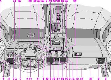
pg. 109 Engine compartment
Engine compartment S40/V40
1 Power brakes 2 - 3 Brake fluid reservoir 4 Fusebox 5 Air cleaner 6 Battery 7 Oil dipstick, automatic transmission 8 Radiator 9 Oil filter 10 Charcoal canister (under fender) 11 Oil dipstick, engine 12 Generator 13 Windshield/headlight washer fluid reservoir 14 Power steering pump 15 Power steering fluid reservoir 16 Oil filler cap, engine 17 Expansion tank, coolant 18 Windshield wiper motor 19 Chassis number
A ABS B Air conditioning compressor C Condenser, air conditioning D Accumulator, air conditioning
WARNING! The coolant fan may start or continue to operate (for up to 6 minutes) after the engine has been switched off.
pg. 110 Fuel/emissions systems
Fuel system
The fuel system is allelectronic and is microprocessorcontrolled. It can continually compensate for variation in engine load, speed and temperature to give the best economy and power. A mass air flow sensor measures the inducted air. In this way the system can make instantaneous adjustments for changes in air temperature or density, thus always assuring the best economy with the lowest possible exhaust emissions.
Heated oxygen sensor
This is an emission control system designed to reduce emissions and improve fuel economy. The heated oxygen sensor monitors the composition of the exhaust gases leaving the engine. The exhaust gas analysis is fed into an electronic module. This adjusts the airfuel ratio to provide optimum conditions for combustion and efficient reduction of the three major pollutants (hydrocarbons, carbon monoxide and oxides of nitrogen (NOx) by a threeway catalytic converter.
Secondary Air Injection (certain models)
This system adds air to the hot exhaust gases as they are expelled from the engine. This causes a secondary combustion of residual hydrocarbons and carbon monoxide, resulting in lower emissions levels in the exhaust gases.
Crankcase ventilation
The engine is provided with positive crankcase ventilation which prevents crankcase gases from being released into the atmosphere. Instead, the crankcase gases are admitted to the intake manifold and cylinders.
Evaporative control system
The car is equipped with an evaporative control system which prevents gasoline vapor from being released into the atmosphere.
The system consists of a fuel tank with filler pipe and cap, a rollover valve, a Fill Limit Vent Valve (FLVV), vapor vent lines, a charcoal canister, a purge line, a purge control valve and engine connections.
In addition, there is a pressure sensor connected to the fuel tank and a filter-protected Canister Close Valve (CCV) on the atmospheric side of the canister, for system diagnosis.
The gasoline vapor is channeled through the rollover valve and the FLVV via the vapor vent lines into the charcoal canister, where it is stored. When the engine is started, the gasoline vapor is drawn from the charcoal canister to the engine's air intake system and into the combustion process.
NOTE:
· If the fuel filler cap is not closed tightly or if the engine is running when the car is refueled, the Malfunction Indicator Lamp may indicate a fault.
· During a transitional period, a small number of service stations may still have fuel nozzles that are not compatible with the fuel filler neck on cars equipped with the evaporative control system (ORVR) mandated by the U.S. Environmental Protection Agency and the California Air Resources Board. If you experience difficulties in refueling your vehicle, please ask the gas station attendant for assistance.
CAUTION:
Fuel must not be siphoned from the fuel tank. This will damage the Evaporative control system.
Contents | Top of Page
2 0 0 0 VOLVO S & V 40
Chapter 9 - Specifications
pg. 119 Specifications
Specifications
This chapter contains facts and figures pertaining to the technical specifications of your car.
Oil/fluids specifications 120
Engine specifications 121
Cooling/fuel/distributor ignition systems 122
Front/rear suspensions 122
Transmission, Capacities, Vehicle loading 123
Electrical system/bulbs 124
Weights 125
Road assistance 126pg. 120 Oil/fluid specifications
Oil quality
Meeting API specification SJ, SJ/CF, or SJ/Energy Conserving.
For best fuel economy and engine protection, consult with your authorized Volvo retailer for recommended oils. Oil with a different quality rating may not provide adequate engine protection.
Synthetic oils complying with oil quality requirements are recommended for: driving in areas of sustained temperature extremes (hot or cold), when towing a trailer over long distances or for prolonged driving in mountainous areas.
Extra oil additives must not be used unless advised by an authorized Volvo retailer.
Viscosity (stable ambient temperatures):
Engine oil Automatic transmission fluid Power steering fluid Brake fluid
Quality: Meeting API specification SG or SH Quality: ATF Dexron III and Mercon Quality: ATF oil Quality: DOT 4+
Capacity (incl. filter): 5.7 US qts (5.4
liters) Capacity: 8 US qts. (7.6 liters) Capacity: 1.05 US qts. (1 liters) Capacity: 0.42 US qts. (0.4 liters)All specifications are subject to change without notice.
pg. 121 Engine
Engine
Liquidcooled gasoline, 4-cylinder, inline engine. Aluminum alloy cylinder block with castiron cylinder liners cast directly into the block. Aluminum alloy cylinder head with double overhead camshafts and separate intake and outlet channels.
Volvo B 4204 T2
160 hp at 5100 rpm (118 kw at 5100 rpm) 170 ft. lbs. at 1800-4800 rpm (230 Nm at 1800-4800 rpm)Engine lubrication is provided by an eccentric pump driven from the crankshaft. Fullflow type oil filter. Exhaust emission control is accomplished by multiport fuel injection, a heated oxygen sensor and a three-way catalytic converter. Designation: Output Max torque Number of cylinders 4
Bore Stroke Displacement Compression ratio Number of valves3.27" (83 mm) 3.54" (90 mm) 1.95 liters 9.0:1
16All specifications are subject to change without notice.
pg. 122 Specifications
Cooling system
Type: Positive pressure, closed system
Thermostat begins to open at 186° F (90° C)
Coolant: Volvo original coolant/antifreeze
Capacity: 6 US qts. (5.7 liters)
Fuel system
The engine is equipped with a multipoint fuel injection system.
Distributor ignition system
Firing order: 13-4-2
Distributor ignition setting: Not adjustable
Spark plugs: Champion RC8PYP or equivalent
Spark plug gap: 0.03" (0.75 mm)
Tightening torque: 18.4 ft. lbs. (25 Nm)
WARNING! The distributor ignition system operates at very high voltages. Special safety precautions must be followed to prevent injury. Always turn the ignition off when:
· Replacing distributor ignition components e.g. plugs, coil, etc.
· Do not touch any part of the distributor ignition system while the engine is running. This may result in unintended movements and body injury.
All specifications are subject to change without notice.
Replacing spark plugs
The spark plugs should be changed according to your service program in your Warranty booklet. However, city driving or fast highway driving may necessitate changing after 15,000 miles (24,000 km) of driving. When installing new plugs, be sure to fit the right type and use correct torque, see "Specifications". When changing the plugs, check that the suppressor connectors are in good condition. Cracked or damaged connectors should be replaced. When changing the spark plugs, clean the terminals and the rubber seals.
Front suspension
Spring strut suspension with integrated shock absorbers and control arms linked to the support frame. Powerassisted rack and pinion steering. Safety type steering column.
The alignment specifications apply to a car at curb weight (without passengers or cargo).
Toe-in measured on the wheel rims: 2,1 mm +- 0,7 mm
Toe-in measured on tire sides: 2,6 mm +- 0,8 mm
Rear suspension
Multilink individual rear wheel suspension with longitudinal support arms, double link arms and track rods.
Toe-in measured on the tire sides: 2,6 mm +- 0,8 mm
pg. 123 Specifications
Power transmission
Automatic transmission: AW 50-42
4speed automatic electronically controlled gearbox comprising a hydraulic torque converter with a lockup function; planetary gear, integrated final drive.
Operation via a floor mounted gear selector lever. Drive shafts with symmetrical joint location. Overdrive.
Final drive ratio 2.76:1
Reduction ratios
1st gear 3.61:1
2nd gear 2.06:1
3rd gear 1.37:1
4th gear 0.98:1
Reverse 3.96:1
Capacities
Fuel tank : 16 US gal. (60 liters)
Cooling system : 6 US qts. (5,7 liters)
Engine oil (incl. filter) : 5.7 US qts. ( 5.4 liters)
Automatic transmission : 8 US qts (7.6 liters)
Power steering fluid : 1.05 US qts (1 liters)
Washer fluid reservoir : 3.9 US qts. (3.75 liters)
Brake system : 0.42 US qts (0.4 liters)
Vehicle loading
The tires on your Volvo should perform to specifications at all normal loads when inflated as recommended on the tire information label. The label is located on the inside of the fuel filler flap. The label lists both tire and vehicle design limits. Do not load your car beyond the load limits indicated.
WARNING! Improperly inflated tires will reduce tire life, adversely affect vehicle handling and can possibly lead to failure resulting in loss of vehicle control without prior warning.
All specifications are subject to change without notice.
pg. 124 Specifications
Electrical system
12 Volt, negative ground.
Voltagecontrolled generator. Singlewire system with chassis and engine used as conductors.
Battery
Voltage: 12 Volt, capacity: 600 A/100 min
The battery contains corrosive and poisonous acids. It is of the utmost importance that old batteries are disposed of correctly. Your Volvo retailer can assist you in this matter.
Generator
Rated output: 120 A
Bulbs Bulb Headlights
US no.
Power
Socket No/bulbs
High beam 55W Low beam 55W
H7
H767
1156
1156
1156
H3Parking lights and Turn signals, front Turn signals, rear Side direction indicators - Tail lights Brake lights Backup lights Rear fog light Front fog lights License plate light (S40) - License plate light (V40) - Door step courtesy lights - Trunk light Vanity mirror lights Front courtesy lights Rear reading lights
3457NA 26/7W/30/2.2cp W2.5 16q 1156
21W/32cp 5W 5W/4cp 21W/32cp 21W/32cp 21W/32cp 55 W 5 W 5 W 10W 5 W 1.2 W 5 W 5 W
BA 15 s W 2.1x9.5 d BA 15 s BA 15 s BA 15 s BA 15 s PK22.5
W 2.1x9.5 d SV8.5
SV8.5
SV 8.5
SV5.5
SV5.5
W 2.1x9.5 dAll specifications are subject to change without notice.
pg. 125 Specifications
Dimensions S40/V40
Length S40/V40
Width S40/V40
Height S40/V40
Wheel base S40/V40
Track, front S40/V40
Track, rear Turning circle: S40/V40
Cargo capacity:176.4 in. (448 cm) 67.7 in. (172 cm) 55.5 in. (141 cm) 100.4 in. (255 cm) 57.1 in. (145 cm) 57.9 in. (147 cm) 34.1 ft. (11.2 m)
39.8 in. (101 cm) S40 (rear seat up) 68.5 in. (174 cm) S40 (rear seat down) 40.2 in. (102 cm) V40 (rear seat up) 68.9 in. (175 cm) V40 (rear seat down) Max width of load opening 27.6 in. (67 cm) Max height of load opening 20.1 in. (51 cm)
841 lbs (382 kg) 837 lbs (380 kg)
2093 lbs (950 kg) 2093 lbs (950 kg)
4180 lbs (1896 kg) 4340 lbs (1969 kg)
Weights Gross Vehicle Weight (GVW): S40
V40
Capacity Weight: S40
V40
Permissible axle weight, front: S40
V40
Permissible axle weight, rear: S40
V40
Permissible axle weight total: S40
V40
Curb weight: S40
V40
The max permissible axle loads or the gross vehicle weight must not be exceeded. Max roof load * Max trailer weight (w/o brakes) (with brakes) Max tongue weight **1100 lbs (500 kg) 2000 lbs (908 kg) 110 lbs (50 kg)
3921 lbs (1780 kg) 3964 lbs (1800 kg)
2996 lbs (1360 kg) 3040 lbs (1380 kg)
1885 lbs (856 kg) 1916 lbs (870 kg)
220 lbs (100 kg)
* For permanent roof racks, check the manufacturer's weight specifications.
** Please refer to section "Trailer towing"
WARNING! When adding accessories, equipment, luggage and other cargo to your vehicle, the total loaded weight capacity of the vehicle must not be exceeded.
All specifications are subject to change without notice.
pg. 126 Road Assistance
Your new Volvo comes with a four year road assistance program named ONCALL. Additional information, features, and benefits are described in a separate information package in your glove compartment.
If you have misplaced your package, dial:
In the U.S.A.
1-800-63-VOLVO (1-800-638-6586)
In Canada:
1-800-263-0475
Volvo supports Voluntary Mechanic Certification by the A.S.E. (pertains to the USA only). Certified mechanics have demonstrated a high degree of competence in specific areas. Besides passing exams each mechanic must also have worked in the field for two or more years before a certificate is issued. These professional mechanics are fully able to analyze vehicle problems and perform the necessary service procedures to keep your Volvo at peak operating condition.
All specifications are subject to change without notice.
Contents | Top of Page
2 0 0 0 VOLVO S & V 40
Chapter 10 - Audio systems
pg. 127 Audio systems
Audio systems
Even if you maintain your car in good running
This chapter describes the audio system in your car.
SC-813 128
SC-816 141
General information 157pg. 128 Audio system SC813
The following pages describe the use of your SC813 Cassette radio and CD remote control
1. On/off (push) 2. · Volume (turn) · Pause/Mute (push) · Balance (pull) 3. Active Sound Control 4. CD changer selector 5. · Tape mode selector · Tape direction selector PROG 6. Bass control 7. Treble control
8. Fader control 9. · Preset buttons - radio · CD-Disc No. selector 10. PROG - Reversing the tape 11. Dolby B NR button 12. Cassette eject 13. Not in use 14. Scan 15. Auto seek memory 16. · Radio - Seek tuning up/down · TP-Next/Previous song · CD-Next UP/Previous DOWN track 17. · Radio - Manual tuning · TP-fast forward/Rewind · CD-Music searchUP/DOWN 18. RND (random order play) button
19. Cassette slot 20. Display 21. Waveband selector (AM) 22. Waveband selectors (FM) 23. Anti-theft LED
TP = Applicable only in Tape Mode
CD = Applicable only when in CD mode and connected to a CD changer.
pg. 129 Anti-theft code
Anti-theft code
The radio features anti-theft circuitry. If the set is removed from the vehicle or if the battery power is disconnected, a special code must be entered to enable operation of the set.
Refer to the radio code card supplied with your vehicle or ask your Volvo retailer for the correct code.
When the car is parked with the ignition key removed, the anti-theft LED will flash. Anti-theft LED
To enter the code
After installation or when the set has been disconnected from power, the set displays "COdE" when it is switched on.
Enter the 4-digit code using the preset buttons.
If the correct code is entered, "on" is displayed and the set is ready to use.
If you enter an incorrect code you must enter the correct code again from the beginning.
Incorrect code
If an incorrect code has been entered "rPt" is displayed. Enter the correct code.
After three unsuccessful coding attempts the set will lock and remain locked for two hours. "OFF" is displayed.
During this waiting period:
· the battery must be connected
· the ignition key must be turned to position I
· the unit must be turned on
Make sure the headlights are turned off to help prevent battery drain (please refer to page 26 for information on turning the headlights off).
Enter the code again once this time has elapsed.
pg. 130 Radio SC-813
A - On/off switch
Push the button to switch on the radio. Press the button slightly longer to turn the radio off.
B - Volume control
Turn the button clockwise to increase the volume. The volume control is electronic and has no end stop.
C - Waveband selector
The desired waveband is set by pressing one of the waveband selector buttons. The frequency and waveband is shown on the display.
NOTE: There are two FM wavebands and one AM waveband. This makes it possible to store 2 x 6 FM stations and 6
AM stations in memory.D - Setting frequency selection
The radio can be used in most parts of the world by changing the frequency selection intervals as follows:
Depress and hold preset button 5 and turn the radio ON. "USA" will flash on the display.
Each time button 5 is pressed, the frequency selection will change from "USA" to "AUS", etc. When the correct country name is displayed, wait 5 seconds and the radio will be ready for use.
E - Manual tuning
Press the left side tune button to tune to lower frequencies and the right side to tune to higher frequencies. The tuned frequency is displayed.
ST will be displayed to indicate stereo FM reception.
pg. 131 Radio SC-813
A - Seek tuning up/down
Press the left side tune button to tune to lower frequencies and the right side to tune to higher frequencies. The radio seeks the next audible station and stops there. If you wish to continue the seek tuning, press the tune button again.
B - Preset programming
1. Tune to the desired frequency.
2. Depress and hold a preset button. The audio will cut out. Keep the button depressed until the audio comes on again (approx. 2 seconds).
3. The frequency is now stored on this preset button.
C - Preset buttons
To select a pre-programed radio frequency, depress the preset button. The set frequency will be displayed.
pg. 132 Radio SC-813
A - Automatic programming (Auto)
Please note that this function will not interfere with pre-stored stations on buttons 1-6.
This function automatically seeks and stores up to 8 strong AM or FM stations.
This is especially useful when travelling in areas where radio stations are unfamiliar.
1. Depress and hold the "AUTO" button for at least 1 second. A number of strong stations (max. 8) on the chosen waveband are now automatically stored in the memory.
If there are no audible stations, "- - - -" is displayed.
B - Bass control
Adjust the bass by sliding the control up or down (up to increase, down to decrease).
A "detent" indicates "equalized" bass.
C - Treble control
Adjust the treble by sliding the control up or down (up to increase, down to decrease).
A "detent" indicates "equalized" treble.
2. Briefly press the "AUTO" button again to retreive one of the newly stored stations. A new station will be retrieved each time the button is pressed again.
pg. 133 Radio SC-813
A - Fader control
Adjust front/rear speaker balance by sliding the control up or down.
(Up to direct more sound to the front speakers, Down to direct more sound to the rear speakers).
The "detent" indicates "equalized" front /rear balance position.
B - Pause function
Press the "volume" knob to temporarily mute the sound. "PAUSE" is displayed.
C - Balance control
Pull out the "volume" knob and adjust the left/right balance by turning the knob counter- clockwise or clockwise.
D - Scan
Press this button to listen to each station for five seconds. Press it again to stop scanning. "Scan" will be displayed during scanning.
E - Active sound control (ASC)
The ASC function automatically adjusts the volume level of the audio system according to driving speed.
To deactivate ASC depress the "ASC" button.
To activate ASC, depress the "ASC" button until "ASC" is displayed.
Contents | Top of Page
2 0 0 0 VOLVO S & V 40
INDEX
pg. 158 - 160 Index
ABS Adjustable steering wheel Air conditioning Air mix Air vents Airbag (SIPS) Airbag (SRS) Alarm Anti-lock Brake System (ABS) Antifreeze Ashtrays Audio systems SC-813
SC-816
Automatic car washing Automatic transmission Driving mode selector Automatic transmission fluid Auxiliary socket Battery Battery maintenance Booster cushion Brake failure warning light Brake fluid Brake fluid warning light Brake system Bulb failure warning Bulbs21,69
32
35
33
33
41
21,69
71,115
31128
141
100
63,64,65,123
63
118,120
3171,124
117
10
20
114,120
20
69,70
20
124Cabin air filter Capacities Center head restraint Central locking button Chains - winter driving Changing a wheel Child booster cushion Child safety Child safety locks - rear doors Clock Concealed storage bin (wagon) Coolant - checking/changing Cooling system Cruise control Cup holders Cupholders Dimensions Doors and locks Drive belt Driving economy Dynamic Stability Assistance (DSA) ECC - Electronic Climate Control Electrical system Electrically operated driver's seat Electrically operated front seats Electrically operated sun roof Electrically operated windows Emergency towing Emergency warning flashers Emissions systems Engine Engine compartment Engine oil Engine oil - checking/changing Fog light - rear Folding rear seat (sedan) Front courtesy lights Front seats Front seats - heated Front suspension Fuel gauge
33
123
39
77
83
10
13
44
18
56
115
64,122
29
51
31,51125
39
115
60
2834,35
65,124
47
46
49
36
66
24
110
121
109
113,120
11222
53
48
45,46
30
122
18Fuel system Fuel tank cover - opening Fuses Gas tank cover - opening Generator Hand brake Handling Hazard warning flashers Heated front seats Heating Heating and air conditioning Hood Ignition switch Immobilizer (start inhibitor) Instruments Integrated booster cushion Jack Jack (sedan) Jump starting Keyless entry system Keylock Keys Label information Locking button - central Locks Long distance trips Lubrication Lumbar support Maintenance schedule Maintenance service Malfunction indicator lamp Manual transmission fluid Mirrors - rear/side view Occupant safety Octane rating Odometer
110,122
59
91,92,9359
12430
56
24
30
35
33
5024
38
16,17
1082
52
6840
61
38104
39
39
72
111
45,46106
105
20
120
4714
59
18113
20
12698
30
20
100
46
114,120Oil - engine Oil pressure warning light On-call Paint touchup Parking brake Parking brake reminder light Polishing Power seats Power steering fluid Radio 128
SC-813
141
SC-816
48
Reading lights 22
Rear fog light 122
Rear suspension Refueling 59
Remote control (central locking system) 40
40
Remote keyless entry system 86,88,89,90
Replacing bulbs Replacing fuses 91
14
Reporting safety defects 56
Roadholding Roof rails/racks 56
Safety defects - reporting Safety locks - child Seat belt maintenance Seat belts Seat belts - cleaning Seats Service reminder indicator Servicing Shift lock Shiftlock release (override) Side Impact Protection System (SIPS) Side-view mirrors - heated SIPS Snow chains Snow tires Spare tire Spare tire (sedan) Spark plugs14
44
14
2,3
101
45
21
108,109
61,62
95
24
77
77
80
52
122Specifications Speed warning SRS SRS diagnostic system SRS warning light Start inhibitor (immobilizer) Starting the engine Steering wheel adjustment Steering wheel lock Storage compartments Studded tires Sun roof Tachometer Tailgate (opening/locking) Temperature gauge Temporary spare tire Tire pressure Tires Tires - changing Tool kit Towing Towing a trailer Traction Control System (TRACS) Trailer towing Trip Computer Trip odometer Turn signals Uniform tire quality grading Upholstery - cleaning Vanity mirrors Vehicle Identification Number (VIN) Vehicle loading Volvo On Call Warning flashers Warning lights Warranty Washer fluid reservoir Washing Waxing Weights
119
25
5,6,7
20
5,20
38
61
32
24
51
77
4918
43
18
80
78
76
83
82
66,67
73
21,70
73
25
18
2379
10148
104
123
12624
20,21
105
116
99
100
12582,83,84
Wheel changing Wheels and tires 76
Whiplash Protection System (WHIPS) 9
Windows - electrically-operated 36
116
Windshield washer nozzles 94
Windshield wiper blades - replacing Winter driving 71Contents | Top of Page
2 0 0 0 VOLVO S & V 40
This manual deals with the operation and care of your Volvo.
Welcome to the worldwide family of Volvo owners. We trust that you will enjoy many years of safe driving in your Volvo, an automobile designed with your safety and comfort in mind. To help ensure your satisfaction with this vehicle, we encourage you to familiarize yourself with the equipment descriptions, operating instructions and maintenance requirements/recommendations in this manual. We also urge you and your passengers to wear seat belts at all times in this (or any other) automobile. And, of course, please do not operate a vehicle if you may be affected by alcohol, medication or any impairment that could hinder your ability to drive.
Your Volvo is designed to meet all applicable safety and emission standards, as evidenced by the certification labels attached to the driver's door opening and on the left wheel housing in the engine compartment. For further information please contact your retailer, or:
In the USA:
Volvo Cars of North America
Customer Relations
P.O. Box 914
Rockleigh, New Jersey 07647-0914
800-458-1552
We also invite you to visit our Home Page on the Internet at:
http://www.volvocars.com
Contents
Contents
Chapter 1 - Occupant safety Chapter 2 - Instruments, switches and controls Chapter 3 - Body and interior Chapter 4 - Starting and driving Chapter 5 - Wheels and tires Chapter 6 - In case of an emergency Chapter 7 - Car care Chapter 8 - Volvo Service Chapter 9 - Specifications Chapter 10 - Audio systems Index
General information
Important
Before you operate your car for the first time please familiarize yourself with the engine oil consumption information and refueling recommendations on pages 58 and 59. You should also be familiar with the information in the first three chapters of this manual.
Information contained in the balance of the manual is extremely useful and should be read after operating the vehicle for the first time.
The manual is structured so that it can be used for reference. For this reason, it should be kept in the car for ready access.
Do not export your Volvo to another country before investigating that country's applicable safety and exhaust emission requirements. In some cases it may be difficult or impossible to comply with these requirements. Modifications to the emission control system(s) may render your Volvo not certifiable for legal operation in the U.S., Canada and other countries.
All information, illustrations and specifications contained in this manual are based on the latest product information available at the time of publication. Please note that some vehicles may be equipped differently, depending on special legal requirements and that optional equipment described in this manual may not be available in all markets.
Volvo reserves the right to make model changes at any time, or to change specifications or design, without notice and without incurring obligation. Shiftlock
When your car is parked, the gear selector is locked in the (P)ark position. To release the selector from this position, turn the ignition key to position II (or start the engine), depress the brake pedal, press the button on the front of the gear slector knob and move the selector from (P)ark.
If it is necessary to manually override the shiftlock system:
· Turn the starting (ignition) key to position I
· Press firmly on the "SHIFTLOCK OVERRIDE" button located at the base of the gear selector
· While holding the override button down, press the button on the front of the gear selector
· Move the selector from the (P)ark position. Keylock
When you switch off the ignition, the gear selector must be in the (P)ark position before the key can be removed. Anti-lock Brake System (ABS)
The ABS system in your car performs a self-diagnostic test when the vehicle first reaches the speed of approximately 12 mph (20 km/h). The brake pedal will pulsate several times and a sound may be audible from the ABS control module. This is normal. Fuel filler door
When you lock the doors, the fuel filler door also locks, with a delay of 10 minutes. When all doors are unlocked, the fuel filler door is also unlocked. Your key, keyless remote, and the door lock button on the dashboard will all unlock the fuel filler door. To open the unlocked fuel filler door, press at the forward edge of the door. See pages 39 for information about locking and unlocking features.
© 1999 Volvo Cars of North America Inc.
Volvo and the environment
Volvo is committed to the well being of our customers. As a natural part of this commitment, we care about the environment in which we all live. Caring for the environment means an everyday involvement in reducing our environmental impact.
Volvo's environmental activities are based on a holistic view, which means we consider the overall environmental impact of a product throughout its complete life cycle. In this context, design, production, product use, and recycling are all important considerations.
In production, Volvo has partly or completely phased out several chemicals including freons, lead chromates, naphtanates, asbestos, mercury and cadmium; and reduced the amount of chemicals used in our plants 50% since 1991.
In use, Volvo was the first in the world to introduce into production a three-way catalytic converter with a Lambda sond, now called oxygen sensor, in 1976. The current version of this highly efficient system reduces emissions of harmful substances (CO, HC, NOx) from the exhaust pipe by approximately 95% and the search to eliminate the remaining emissions continues. Volvo is the only automobile manufacturer to offer CFC-free retrofit kits for the air
conditioning system for all models as far back as the M/Y 1975 240. Advanced electronic engine controls, refined purification systems and cleaner fuels are bringing us closer to our goal.
After Volvo cars and parts have fulfilled their use, recycling is the next critical step in completing the life cycle. The metal content is about 75% of the total weight of a car, which makes the car among the most recycled industrial products. In order to have efficient and well controlled recycling, many Volvo variants have printed dismantling manuals, indicating the weight and material of individual components. For Volvo, all homogeneous plastic parts weighing more than 1.7 oz. (50 grams) are marked with international symbols that indicate how the component is to be sorted for recycling.
In addition to continuous environmental refinement of conventional gasoline-powered internal combustion engines, Volvo is actively looking at advanced technology alternative-fuel vehicles.
When you drive a Volvo, you become our partner in the work to lessen the car's impact on the environment.
To reduce your vehicle's environmental impact, you can:
· Maintain proper air pressure in your tires. Tests have shown decreased fuel economy with improperly inflated tires
· Follow the recommended maintenance schedule
· Drive at a constant speed
· See an authorized Volvo retailer as soon as possible for inspection if the check engine (malfunction indicator) lamp illuminates, or stays on after the vehicle has started
· Properly dispose of any vehicle related waste such as used motor oil, used batteries, brake pads, etc.
· When cleaning your car, use Volvo's own car care products, all of which have systematically been adapted to the environment
For additional information regarding the environmental activities in
which Volvo Cars of North America, Inc. and Volvo Car Corporation are involved, visit our Internet Home Page at:
http://www.volvocars.com
Top of Page
2 0 0 0 VOLVO S & V 40
Chapter 1 - Occupant safety
pg. 1 Occupant safety
Occupant safety
Not wearing a seat belt is like believing "It'll never happen to me!" Volvo, the inventor of the three-point seat belt, urges you and all adult occupants of your car to wear seat belts and ensure that children are properly restrained, using an infant, car or booster seat determined by age, weight and height. Volvo also believes no child should sit in the front seat of a car and that no one under 4 feet 7 inches should ride as a passenger in the front seat of any vehicle equipped with a passenger side airbag.
Fact: In every state and province, some type of child-restraint legislation has been passed. Additionally, most states and provinces have already made it mandatory for occupants of a car to use seat belts.
So, urging you to "buckle up" is not just our recommendation - legislation in your state or province may mandate seat belt usage. The few seconds it takes to buckle up may one day allow you to say, "It's a good thing I was wearing my seat belt".
Seat belts 2
Volvo SRS 4
Side Impact Protection System - (SIPS) air bag 8
Child safety 9
Occupant safety 14
Reporting Safety Defects 14pg. 2 Seat belts
Seat belts
Always fasten the seat belts before you drive or ride.
Two lights above the rear view mirror will be illuminated for 4-8 seconds after the starting
(ignition) key is turned to the driving position. A chime will sound at the same time if the
driver has not fastened his seat belt. The rear seats are provided with self- retracting inertial
reel belts. The front seats are provided with single roller belts with tensioners.
To buckle:
Pull the belt out far enough to insert the latch plate into the receptacle (buckle for rear seats)
until a distinct snapping sound is heard. The seat belt retractor is normally "unlocked" and
you can move freely, provided that the shoulder belt is not pulled out too far. The retractor will lock up as follows:
· if the belt is pulled out rapidly
· during braking and acceleration
· if the vehicle is leaning excessively
· when driving in turns
For the seat belt to provide maximum protection in the event of an accident, it must be worn correctly. When wearing the seat belt remember:
· The belt should not be twisted or turned.
· The lap belt must be positioned low on the hips (not pressing against the abdomen).
· The shoulder section of the front seat >belts adjusts automatically to the driver's height.
Adjusting the shoulder belt
Make sure that the shoulder belt is rolled up into its retractor and that the shoulder and lap
Lap portion of the seat belt should sit low
belts are taut.
Before exiting the car, check that the seat belt retracts fully after being unbuckled. If necessary, guide the belt back into the retractor slot.
NOTE: Legislation in your state or province may mandate seat belt usage.
WARNING! Any device used to induce slack into the shoulder belt portion of the three-point belt system will have a detrimental effect on the amount of protection available to you in the event of a collision. The seat back should not be tilted too far back. The shoulder belt must be taut in order to function properly.
WARNING! Do not use child safety seats or child booster cushions/backrests in the front passenger's seat. We also recommend that children who have outgrown these devices sit in the rear seat with the seat belt properly fastened.
pg. 3 Seat belts, Head restraints
During pregnancy
Pregnant women should always wear seat belts. Remember that the belt should always be positioned in such a way as to avoid any possible pressure on the abdomen. The lap portion of the belt should be located low, as shown in the above illustration.
WARNING! Never use a seat belt for more than one occupant. Never wear the shoulder
portion of the belt under the arm, behind the back or otherwise out of position. Such use could cause injury in the event of an accident. As the seat belts lose much of their strength when exposed to violent stretching, they should be replaced after any collision, even if they appear to be undamaged. Never repair the belt on your own; have this work done by an authorized Volvo retailer only.
Rear head restraints
The rear head restraints can be adjusted according to the passenger's height. The restraint should be carefully adjusted to support the occupant's head.
The head restraint can be raised by pulling straight up or lowered by pressing the catch (1) at the base of the left head restraint support and pushing down.
pg. 4 Volvo SRS
Passenger side SRS hatch
As an enhancement to the three-point seat belt system, your Volvo is equipped with a Supplemental Restraint System (SRS). The Volvo SRS consists of an airbag (2) on both the driver's and passenger's sides and seat belt tensioners in both front door pillars (4). The system is designed to supplement the protection provided by the three-point seat belt system.
The SRS system is indicated by the "SRS" embossed on the steering wheel pad and above the glove compartment, and by decals on both sun visors and on the far right side of the dash.
The airbags are folded and located in the steering wheel hub and above the glove compartment. They are designed to deploy during certain frontal or front-angular collisions, impacts, or decelerations, depending on the crash severity, angle, speed and object impacted. The airbags may also deploy in certain non-frontal collisions where rapid deceleration occurs.
The airbag system includes gas generators (1) surrounded by the airbags (2) and front seat belt tensioners for both of the front seats (4). To deploy the system, the sensor (3) activates the gas generators causing the airbags to be inflated with nitrogen gas. As the movement of the seats' occupants compresses the airbags, some of the gas is expelled at a controlled rate to provide better cushioning. Both seat belt tensioners also deploy, minimizing any seat belt slack.
The entire process, including inflation and deflation of the airbags, takes approximately two-tenths of a second.
WARNING!
· As its name implies, SRS is designed to be a SUPPLEMENT to - not a replacement for - the three-point belt system. For maximum protection, wear seat belts at all times. Be aware that no system can prevent all possible injuries that may occur in an accident.
· When installing any optional equipment, make sure that the SRS system is not damaged. Do not attempt to service any component of the SRS yourself. Attempting to do so may result in serious personal injury. If a problem arises, take your car to the nearest authorized Volvo retailer for inspection as soon as possible.
pg. 5 Volvo SRS
A self-diagnostic system incorporated into the sensor monitors the SRS. If a fault is detected, the "SRS" warning light will illuminate. The light is included in the warning/indicator light cluster in the instrument panel. Normally, the SRS warning lamp should light up when the ignition is switched on and should go out after 5 seconds or when the engine is started. Check that this light is functioning properly every time the car is started.
The following items are monitored by the self-diagnostic system:
· Sensor unit
· Cable harness
· Gas generator igniters
WARNING!
Never drive an SRS equipped car with your hands on the steering wheel pad / airbag housing.
No objects, accessory equipment or stickers may be placed on, attached to or installed near the SRS cover in the center of the steering wheel, the SRS cover above the glove compartment or the area affected by airbag deployment.
If the SRS warning light stays on after the engine has started or if it comes on while you are driving, drive the car to the nearest authorized Volvo retailer for inspection as soon as possible.
SRS decal on door pillar driver's side
There is no maintenance to perform on the SRS yourself. The month and year shown on the decal on the door pillar indicate when you should contact your Volvo retailer for specific servicing or replacement of airbags and seatbelt tensioners. This service must be performed by an authorized Volvo retailer.
Should you have any questions about the SRS system, please contact
your authorized Volvo retailer or Volvo Customer Support:
In the USA:
Volvo Cars of North America
Customer Relations
P.O. Box 914
Rockleigh, New Jersey 07647-0914
800-458-1552
pg. 6 Volvo SRS
SRS texts on inside of both sun visors
SRS texts on outside of both sun visors
SRS texts on the passenger's dash
SRS text at far right of instrument panel
WARNING! Do not use child safety seats or child booster cushions/backrests in the front passenger's seat. We also recommend that children who have outgrown these devices sit in the rear seat with the seat belt properly fastened.
NOTE: Deployment of SRS components occurs only one time during an accident. In a collision where deployment occurs, the air bags and seat belt tensioners activate. Some noise occurs and a small amount of powder is released. The release of the powder may appear as smoke-like matter. This is a normal characteristic and does not indicate fire.
NOTE: NOTE: Volvo's dual-threshold air bags use special sensors that are integrated with the front seat buckles. The point at which the air bag deploys is determined by whether or not the seat belt is being used, as well as, the severity of the collision. Collisions can occur where only one of the airbags deploys.
WARNING!
· Children must never be allowed in the front passenger seat. Volvo recommends that ALL occupants (adults and children) shorter than 4 feet 7 inches (140 cm) be seated in the back seat of any vehicle with a front passenger side airbag. See page 11 for guidelines.
· Occupants in the front passenger's seat must never sit on the edge of the seat, sit leaning toward the instrument panel or otherwise sit out of position. The occupant's back must be as upright as comfort allows and be against the seat back with the seat belt properly fastened.
· Feet must be on the floor, e.g. not on the dash, seat or out of the window.
· No objects or accessory equipment, e.g. dash covers, may be placed on, attached to or installed near the SRS hatch (the area above the glove compartment) or the area affected by airbag deployment (see illustration).
· There should be no loose articles, e.g. coffee cups, on the floor, seat or dash area.
· Never try to open the SRS cover on the steering wheel or the passenger side SRS seam. This should only be done by an authorized Volvo service technician.
· Failure to follow these instructions can result in injury to the vehicle occupants in an accident.
pg. 7 Volvo SRS
NOTE: The information on this page does not pertain to the Side Impact Protection System airbags. When are the airbags deployed?
The SRS system is designed to deploy during certain frontal or frontangular collisions, impacts, or decelerations, depending on the crash severity, angle, speed and object impacted. The SRS sensor is designed to react to both the impact of the collision and the inertial forces generated by it and to determine if the intensity of the collision is sufficient for the airbags to be deployed.
WARNING! The SRS is designed to help prevent serious injury. Deployment occurs very quickly and with considerable force. During normal deployment and depending on variables such as seating position, one may experience abrasions, bruises, swellings, or other injuries as a result of airbag(s) deployment.
If the airbags have been deployed, we recommend the following:
· Have the car towed to an authorized Volvo retailer. Never drive with the airbags deployed.
· Have an authorized Volvo retailer replace the SRS system components.
· Use only new, Genuine Volvo Parts when replacing SRS components (airbags, seat belts, tensioners, etc.). When are the airbags NOT deployed?
Not all frontal collisions activate the SRS system. If the collision involves a nonrigid object (e.g., a snow drift or bush), or a rigid, fixed object at a low speed, the SRS system will not necessarily deploy. Front airbags do not normally deploy in a side impact collision, in a collision from the rear or in a rollover situation. The amount of damage to the bodywork does not reliably indicate if the airbags should have deployed or not. Seat belts the heart of the Volvo safety system
The heart of the Volvo safety system is the threepoint seat belt (a Volvo invention)! In order for the SRS system to provide the protection intended, seat belts must be worn at all times by everyone in the car. The SRS system is a supplement to the seat belts.
WARNING! If your car has been subjected to flood conditions (e.g. soaked carpeting/standing water on the floor of the vehicle) or if your car has become flooddamaged in any way, do not attempt to start the vehicle or put the key in the ignition before disconnecting the battery (see below). This may cause airbag deployment which could result in personal injury. Have the car towed to an authorized Volvo retailer for repairs.
Before attempting to tow the car, use the following procedure to override the shiftlock system to move the gear selector to the neutral position.
· Disconnect the battery
· Wait at least one minute
· Insert the key in the ignition and turn it to position 1
· Press firmly on the shiftlock override button (located near the base of the gear selector).
· While holding the override button down, move the gear selector from the park position.
WARNING! Never drive with the airbags deployed. The fact that they hang out can impair the steering of your car. Other safety systems can also be damaged. The smoke and dust formed when the airbags are deployed can cause skin and eye irritation in the event of prolonged exposure.
Contents | Top of Page
2 0 0 0 VOLVO S & V 40
Chapter 2 - Instruments, switches and controls
pg. 15 Instruments, switches and controls
Instruments, switches and controls
Instruments, switches, controls etc. are described on the following pages.
Instruments 17
Warning lights 20
Lights 22
Wipers 23
Hazard warning, Heated window, mirrors 24
Trip Computer 25
Dynamic Stability Assistance 28
Cruise control 29
Heated seats, Parking brake 30
Ashtrays 31
Steering wheel adjustment 32
Heating, Ventilation 33
Electrcaly operated windows 36pg. 16 Instruments, switches and controls
pg. 17 Instruments, switches and controls
Chapter 2 - Instruments, switches and controls The pages in this section provide detailed descriptions of the vehicle's instruments and controls. Note that vehicles may be equipped differently, depending on special legal requirements.
Page 47
34
33
22
31
22
22
29
181 Adjustable door mirrors 2 Defroster side windows 3 Air vents 4 Light switch 5 Cup holder 6 Foglight switch 7 Dimmer instrument lighting 8 Turn signals, high/low beams, Home Safe Lighting, cruise control 9 Instruments 10 Horn 23
11 Windshield wash/wipe, headlight wash/wipe 34
12 Fan 34
13 Air distribution control (ECC: temperature control) 24
14 Hazard warning flashers 33
15 Mixing outside air, air vents 33
16 Air flow, air vents 34
17 Temperature control (ECC: temperature control) 43
18 Glove compartment 19 Passenger airbag 20 Light-sensitive diode for Electronic Climate Control and LED for immobilizer and alarm 35
91
21 Fuse box22 Hood latch 23 Steering wheel height adjustment 24 ECC temperature sensor 25 Recirculation 26 Door lock switch 27 - 28 Trip Computer operation 29 Seat heater 30 DSA switch (Dynamic Stability Assistance) 31 Seat heater 32 Rear window/door mirror heater switch 34 ECC: air-conditioning switch 35 Automatic transmission switch 36 Door mirror switch 37 Electric window switch front 38 Cut-out switch windows rear 39 Electric window switch rear
50
32
34
35
3925
30
28
30
34
34
63
47
36
36
36Controls in center console Some of the items listed on this page are available on certain models only.
pg. 18 Instruments
1 Clock reset knob Turn the knob: Clockwise: advance Counterclockwise: set clock back The longer the knob is turned, the faster the setting will change.
2 Clock
3 Tachometer Reads thousands of engine rpm. The needle should never be in the solid red range.
4 Trip odometer reset button Press the button to reset the trip odometer. The ignition must be switched on.
5 Odometer
6 Speedometer
7 Trip odometer Used for measuring shorter distances. The last digit indicates 1/10 mile/kilometer.
8 Fuel gauge Fuel tank capacity: 16 US gallons (60 liters). When the warning light comes on there is approximately 1.5 US gal. (7 liters) of fuel remaining. See "Refueling" for additional information. When refuelling the fuel gauge needle will not register until the volume of gasoline in the tank exceeds 3.5 US gal. (12 liters).
9 Trip Computer/Ambient temperature
NOTE: See page 26/27 for information on the trip computer.
10 Temperature gauge (engine coolant) Do not drive the car with the pointer in the red range. The pointer should be approximately midway on the gauge face when driving. If the pointer approaches the red range repeatedly, check coolant level. See page 116.
pg. 19 Indicator and warning lights
1 Turn signal, left 2 Turn signal, right 3 Fuel level low 4 Not in use 5 Front fog lamp on 6 Rear fog lamp on 7 Cruise control 8 Brake light* failure warning. 9 Main beam on 10 ABS (anti-lock brakes) malfunction 11 Door open 12 Parking brake applied 13 Low oil pressure 14 Hazard warning light on 15 Fault in SRS system 16 Brake circuit not working (brake fluid level too low) and EBD 17 Battery charge failure
18 Not in use 19 DSA (option) 19 Not in use 20 Automatic transmission: position W, 3 or L or MIL** 21 Check engine light 22 Immobilizer on or MIL** 23 Service Reminder Indicator 24 Not connected 25 Low washer fluid level 26 Turn indicator trailer (certain models)
Starting check After a few seconds, all lights except 10 and 22 will go out. Once the engine starts, 10 and 22 will also go out.
* Indicates failure of a brake light, not failure of the braking system (see item 16).
**MIL = Check Engine Lamp pg. 20 Warning lights
The warning lights described on pages 20 and 21 should never stay on when driving
When the ignition key is turned on and before the engine starts, all of the warning lights should go on to test the function of the bulbs. Should a light not go off after the engine has started, the system indicated should be inspected. However, the parking brake reminder light will not go off until the parking brake has been fully released.
Supplemental Restraint System (SRS)
If the light comes on (or stays on after the vehicle has started), the SRS diagnostic system has detected a fault. Drive to an authorized Volvo retailer for an inspection of the system. See the SRS section for more information.
Check Engine Lamp
If the lamp comes on (or stays on after the vehicle has started), the engine diagnostic system has detected a possible fault in the emission control system. Although driveability may not be affected, see an authorized Volvo retailer as soon as possible for inspection.
NOTE: If the fuel filler cap is not closed tightly or if the engine is running when the car is refueled, the Check Engine Lamp may indicate a fault. However, your vehicle's performance will not be affected. Use only Volvo original or approved fuel filler caps.
Oil pressure warning light
If the light comes on while driving, stop the car and then stop the engine immediately and check the engine oil level. See page 112. If the light stays on after restart, have the car towed to the nearest authorized Volvo retailer. After hard driving, the light may come on occasionally when the engine is idling. This is normal, provided it goes off when the engine speed is increased.
Parking brake reminder light
This light will be on when the parking brake (hand brake) is applied. The parking brake lever is situated between the front seats. WARNING!
If the fluid level is below the MIN mark in either section of the reservoir: DO NOT DRIVE. Tow the car to a Volvo retailer and have the brake system checked and any leakage repaired.
Brake failure warning light
If the light comes on while driving or braking, stop immediately, open the hood and check the brake fluid level in the reservoir. See page 114 for reservoir position.
If the control lamp still stays on, the EBD (Electronic Brakeforce Distribution) is not working.
Drive to your Volvo dealer. See ABS control lamp and also page 69.
Bulb failure warning light
The light will come on if one of the brake light bulbs are defective when the brake pedal is pressed.
Check the fuse and bulb. See sections "Replacing bulbs" and "fuses. pg. 21 Warning lights, Daytime Running Lights
DSA (option)
Dynamic Stability Assistance This is a system which helps keep the drivewheels from spinning. The light flashes if the road surface is slippery, the wheels are spinning and the system is working.
The control light comes on if a fault occurs in the DSA system. It also comes on if the system is switched off via the switch.
For more information see page 28.
Service reminder indicator
This light will come on according to preset service intervals or after 750 hours of driving or after 12 months, whichever occurs first. It is a reminder to the driver that the service interval has been exceeded. The light will stay on for 2 minutes after start until reset by the servicing retailer.
Anti-lock Brake system (ABS)
If the warning lamp lights up there is a malfunction of the ABS system (the standard braking system will however function). The vehicle should be driven to a Volvo retailer for inspection.
See page 69 for additional information.
Daytime Running Lights:
The S40 and V40 come from the factory with daytime running lights activated. Carry out the following steps if you will deactivate them. These steps may be carried out again to reactivate and deactivate the daytime running lights as desired.
Programming for On or OFF
Turn the headlight switch to position
Turn the ignition key in position II.
Pull the turn signal lever towards you and hold it while turning the headlight switch to position 0.
If the green light underneath the headlight switch is on the daytime running lights are on.
WARNING!
Do not activate or deactive the Daytime Running Lights while driving.
pg. 22 Headlights, Parking lights, Instrument illumination, Fog lights
1 Headlights and parking lights
A green lamp (3) below the switch indicates when the lighting is on. 0 Switch position
Ignition key in positions 0+I: All lights switched off Ignition key in position II: Low beam headlights on (+ front and rear parking lights, license plate light and instrument lighting). Switch position Parking lights front and rear. Ignition key in positions 0, I and II Parking lights should only be used when the car is parked, never when the car is being driven. It also switches on the position lights in bumpers, and license plate light (and the instrument lights in position II). Switch position Ignition key in positions 0 and I: All lights off. Ignition key in position II: Headlights on (+ parking lights front and rear,license plate light, position lights in the bumpers and instrument lights).
Note: You have to turn the light switch to this position in order to switch on high beams.
Rear fog light * The rear fog light (located in the driver's side tail light cluster) is considerably brighter than the normal tail lights and should be used only when the atmospheric conditions, such as fog, rain, snow, smoke or dust reduce the daytime or nighttime visibility of other vehicles to less than 500 ft (150 meters).
Fog lights
Ignition key must always be in position II.
Headlight or parking lights must be activated
- Front fog lights (option): press
- Rear fog light: press
- headlights or front fog lights must be activated
Switching fog lights off
To switch the fog lights off, press the appropriate fog light switch again.
If headlights or parking lights are switched off, the fog lights will also go out. The fog lights are also switched off when the ignition is switched off and must be switched back on manually if required when the ignition is switched on again.
The fog lights switch off automatically when the high beams are switched on.
2 Dimmer instrument lighting
Instrument lighting can be dimmed to 6% of maximum lighting. + brighter
- darker * By design, there is one rear fog light only, located in the driver's side tail light cluster.
pg. 23 Turn signals, Home Safe lighting, Wipers/washers
Turn signals
Wipers/washers
Turn signals
1 Lane change position. In maneuvers such as lane changing, the driver can flash the turn signals by moving the turn signal lever to the first stop and holding it there. The lever will return to the neutral position when released.
2 Signal lever engaged for normal turns.
3 High beam/low beam switch (headlights on). Move the lever towards the steering wheel and release it.
4 Headlight flasher (headlights off).
Move the lever towards the steering wheel. The headlight high beam will be on until the lever is released.
NOTE: A defective turn signal bulb will cause the turn signal indicator and remaining signal lights to flash more rapidly than normal.
Home Safe lighting
When you leave your car at night, you can make use of the exterior courtesy lighting function:
· Remove the key from the ignition switch.
· Pull the turn signal lever towards the steering wheel (as when using the headlight flasher function).
The low beam headlights will now remain on for 30 seconds to light your way.
Repeat the above measures if you want to switch off the Home Safe Lighting.
Wipers/washers
1 "Single sweep" position:
The switch returns automatically when released.
2 Intermittent wiper
The wipers will sweep approximately every 5 seconds (car speed depending).
3 Wipers, normal speed
4 Wipers, high speed
5 Windshield wiper/washer, headlight wiper/washer. The wipers will make 23 sweeps across the windshield and headlights and 1 sweep after 3 seconds.
6 Tailgate window wiper (V40)
The tailgate wiper switch has two positions:
OFF
ON : intermittent and synchronized with windshield wiper
Tip function
When pressing switch 7 briefly the wiper will make one sweep, independent of the interval
Backing up
When the gearlever is moved towards rear and the windshield wipers are on, the rear window wiper will come on for two sweeps.
7 Tailgate window washer (V40)
The washer keeps working for as long as you keep the button depressed.
The wiper will make 2-3 sweeps after the lever is released and 1 sweep after 3 seconds.
Contents | Top of Page
2 0 0 0 VOLVO S & V 40
Chapter 3 - Body and interior
pg. 37 Body and interior
Body and interior
The seats, sun roof, mirrors, etc. are described on the following pages.
Keys 38
Doors and locks 39
Alarm 41
Trunk/tailgate 43
Child safety locks 44
Front seats 45
Rear/side view mirrors 47
Interior lights, Vanity mirror 48
Sun roof 49
Hood 50
Storage compartments 51
Trunk light, Spare tire, Jack 52
Folding rear seat 53
Folding front seat, Luggage strap 54
Side cargo net, Luggage net 55
Weight distribution, Handling, Roadholding, Roofrack 56pg. 38 Keys
Key
The key activates all locks (ignition switch/steering wheel lock, all doors, trunk/tailgate, fuel filler door and glove compartment).
Immobilizer (start inhibitor)
Each of the keys supplied with your car is electronically coded. When the key is inserted into the igniton switch, the code is transmitted to and compared with a code stored in the start inhibitor module. The car can only be started if a properly coded key is used.
If you misplace a key, take the other keys to an authorized Volvo retailer. The existing code in the start inhibitor module and all the keys will be erased as an antitheft measure and a new code will be programmed in.
NOTE:
You should never keep more than one of your ignition keys on the ring at the same time. This could cause conflicting signals to be transmitted to the ignition switch, making it impossible to start the car.
This device complies with part 15 of the FCC rules. Operation is subject to the following condition: (1) This device may not cause harmful interference, and (2) this device must accept any interference received, including interference that may cause undesired operation.
pg. 39 Doors and locks
Doors and locks
Your car is equipped with a central locking system.
The key, used on the driver's door, the remote control, or central locking button, will lock/unlock all doors, trunk/tailgate.
Turn the key once to unlock the driver's door and the fuel filler door.
Turn the key again within 10 seconds to unlock other doors, trunk/tailgate.
One turn with the key towards "lock" in the driver's door locks all doors, trunk/tailgate and fuel filler door with a 10
minutes delay in the fuel filler door.WARNING!
If the doors are locked while driving, this may hinder rapid access to the occupants of the car in the event of an accident. (Also see information on "Child safety locks").
Central locking button
Central locking button
The central locking button (1) can be used to lock or unlock all doors and trunk/tailgate.
Lock: Press the lower side of the button.
Unlock: Press the upper side of the button.
Note:As long as ignition is on, you can always lock or unlock with the central locking button.
With ignition off and 25 seconds after having locked all doors and trunk/tailgate with the key or with the remote control, the central locking button will not lock or unlock the car any more.
Note: If the key is in the ignition switch and you close the driver's door, the driver's door will be immediately unlocked again in order to prevent accidentally locking the car with the keys left inside the car.
pg. 40 Remote keyless entry system
Remote keyless entry system
Your car is equipped with a remote control transmitter. This transmitter uses a radio frequency which will allow "keyless" entry into the passenger compartment or the trunk. You will be supplied with two coded key ring transmitters, which will enable you to lock/unlock all doors and the trunk/tailgate and fuel filler door from a distance of 10-15 feet (3-5 meters).
The Remote also activates/deactivates the alarm system that comes standard with this car.
The car can also be locked/unlocked with the key.
Using the remote control
· Press the LOCK button once to lock all doors and trunk/tailgate.
· Press the UNLOCK button once to unlock the driver's door and the fuel filler door only. Press this button again (within 10 seconds) to unlock other doors, trunk/tailgate.
· Press the OPEN trunk/tailgate button to unlock the tailgate/trunk.
This device complies with FCC rules Part 15. Operation is subject to the following two conditions: (1) This device may not cause harmful interference and (2) this device must accept any interference that may be received, including interference that may cause undesired operation.
NOTE: If only the driver's door is unlocked, the lock will automatically reengage (re-lock) and the alarm will be set after 2 minutes unless the door has been opened (see page 42).
The lock/unlock and alarm features can also be utilized by using the keys. See section: Doors and Locks on page 39.
WARNING! Volvo does not recommend using the transmitter to lock the doors from inside the car. The alarm would be activated and would sound when one of the doors is opened. The doors must not be locked using the remote transmitter while the vehicle is occupied. In case of an accident, this may hinder rapid access to the occupants of the vehicle.
Remote control not functioning.
If the remote control is not functioning the car can be started as follows:
Open the driver's door with the key. The alarm and alarm siren will activate.
Turn the ignition on. The alarm will deactivate.
Note: The remote control will not function if a key is left in the ignition switch.
pg. 41 Alarm
Alarm
The radio signal emitted from the transmitter, which is used to set/unset the alarm, is a "rolling code" signal. This means that the signal is changed randomly for each transmission and is intended to help prevent unauthorized recording of the code.
When armed (set), the alarm continuously monitors a number of points on the car. The following conditions will set off the alarm: · The hood is opened · The trunk/tailgate is opened · A door is opened · The ignition switch is tampered with
The alarm will sound for 30 second intervals, with a 10 second pause between intervals. This function cannot be interrupted. · If the battery or the siren are disconnected, the alarm will sound for five minutes
Arming (setting) the alarm
Press the LOCK button on the remote control, lock the car using the key in the driver's door . One long flash of the turn signals will confirm that the alarm is set.
Disarming the alarm
Press the UNLOCK button on the remote control or unlock the driver's door with the key.
Turning off (stopping) the alarm
If the alarm is sounding, it can be stopped by pressing the UNLOCK button on the remote control or by unlocking the driver's door with the key.
Visual alarm signal
The visual alarm signal is given by flashing all turn signals and turning on the interior lighting for approximately 5
minutes.Audible alarm signal
An audible alarm signal is given by the backup siren. One alarm cycle lasts for 30 seconds.
"Panic" function
In an emergency situation, this feature can be used to attract attention, if you are within 10-15 feet (3-5) meters of the car. .
Activate the "panic" function by pressing the red panic button on the remote control for at least 3 seconds or by pressing this button twice within 3 seconds. The turn signals will flash, the interior lights will go on and the alarm will sound.
The "panic" alarm can be turned off after 5 seconds by pressing any of the buttons on the remote control or it will stop automatically after 25 seconds.
NOTE: This button will NOT unlock the car.
pg. 42 Alarm
LED alarm status signals
The status of the alarm system is indicated by the red LED at the right side of the dash:
· LED off - the alarm is not armed (set)
· LED flashes once per second - the alarm is armed (set)
· LED flashes rapidly before the ignition is switched on - the alarm has been triggered
· LED flashes rapidly for 15 seconds after the ignition has been switched on - a fault has been detected in the alarm system. Contact a Volvo retailer.
Automatic relock
If only the driver's door is unlocked with the remote control, the lock will automatically reengage (re-lock) and the alarm will be set after 2 minutes unless the door has been opened.
Batteries
Each remote transmitter is powered by two three-volt batteries, type CR 2016. If the range of the transmitter is noticeably reduced, this indicates that the battery is weak and should be replaced.
Replacement: Open the remote control by twisting a coin in the ring between front and back (leave the ring in place). Replace the batteries. Reinstall the cover, making sure it is secured tightly to help protect the transmitter.
CAUTION: Do not attempt to service or repair any components of the alarm system yourself. This should only be done by an authorized Volvo retailer.
pg. 43 Trunk/Tailgate, Glove compartment
Opening/unlocking the trunk/tailgate