- Download PDF Manual
-
The trunk/tailgate locks are incorporated in the central locking system and are locked or unlocked when the driver's door is locked/unlocked.
A - Remove key vertically: Trunk/tailgate remains locked (disconnected from the central locking system). B - Turn key clockwise and remove: Trunk/tailgate are locked/unlocked with the central locking system). C - Turn key counterclockwise: Insert key and open lock without using central locking system. The key cannot be removed.
Glove compartment
The glove compartment can be locked with the key.
A unlocked
B locked
Contents | Top of Page
2 0 0 0 VOLVO S & V 40
Chapter 4 - Starting and driving
pg. 57 Starting and driving
Starting and driving
This section on starting and driving contains items such as starting the engine, operating the gear selector, towing, trailers, etc.
Fuel requirements, Refueling 58
Driving economy 60
Starting the engine 61
Automatic transmission 62
Points to remember 64
Emergency towing 66
Vehicle towing information 67
Jump starting 68
Brake system, ABS 69
Electronic Brake Force Distribution 70
Winter driving 71
Long distance trips 72
Trailer towing 73pg. 58 Fuel requirements
NOTE ENGINE OIL:
Although some oil consumption occurs during normal engine operation, more oil is consumed when the engine is new as the internal parts generate higher friction while wearingin to each other. From the time the engine is new until the first service is performed, the oil consumption could be higher than normal. For this reason, it is especially important to check the oil every time you refuel your car during this period. See page 112.
Deposit control gasoline (detergent additives)
Volvo recommends the use of gasoline containing deposit control additives. These additives have shown to be efficient in keeping injectors and intake valves clean. Consistent use of deposit control gasolines will help ensure good driveability and fuel economy. If you are not sure whether the gasoline contains deposit control additives, check with the service station operator.
Unleaded fuel
Each Volvo has a three-way catalytic converter and must use only unleaded gasoline. U.S. and Canadian regulations require that pumps delivering unleaded gasoline be labelled "UNLEADED". Only these pumps have nozzles which fit your car's filler inlet. It is unlawful to dispense leaded fuel into a vehicle labelled "unleaded gasoline only". Leaded gasoline damages the three-way catalytic converter and the heated oxygen sensor system. Repeated use of leaded gasoline will lessen the effectiveness of the emission control system and could result in loss of emission warranty coverage. State and local vehicle inspection programs will make detection of misfueling easier, possibly resulting in emission test failure for misfueled vehicles.
NOTE: Some U.S. and Canadian gasolines contain an octane enhancing additive called methly-cyclopentadienyl manganese tricarbonyl (MMT). If such fuels are used, your Emission Control System performance may be affected, and the Check Engine Lamp located on your instrument panel may light. If this occurs, please return your vehicle to an authorized Volvo retailer for service.
pg. 59 Fuel requirements, Refueling
Octane rating
Volvo engines are designed for optimum performance on unleaded premium gasoline with an octane rating. AKI of 91, or above. AKI (ANTI KNOCK INDEX) is an average of the Research Octane Number, RON, and the Motor Octane Number, MON. (RON + MON/2).
The minimum octane requirement is AKI 87 (RON 91).
Gasoline containing alcohol and ethers
"Oxygenated fuels"
Some fuel suppliers sell gasoline containing "oxygenates" which are usually alcohols or ethers. In some areas, state or local laws require that the service pump be marked indicating use of alcohols or ethers. However, there are areas in which the pumps are unmarked. If you are not sure whether there is alcohol or ethers in the gasoline you buy, check with the service station operator. To meet seasonal air quality standards, some areas require the use of "oxygenated" fuel.
Volvo allows the use of the following "oxygenated fuels; however, the octane ratings listed on this page must still be met.
Alcohol — Ethanol
Fuels containing up to 10% ethanol by volume may be used.
Ethanol may also be referred to as Ethyl alcohol, or "Gasohol".
Ethers — MTBE
Fuels containing up to 15% MTBE may be used.
Refueling
The fuel tank is designed to hold approximately: 16 US gallons (60 liters) with sufficient volume left over to accommodate possible expansion of the fuel in hot weather.
Fuel filler door
The fuel filler door (on the left rear fender) is unlocked along with the car's central locking system.
Open fuel filler cap slowly during hot weather conditions.
See page 95 in case the fuel filler door does not unlock along with the central locking system
CAUTION:
· Do not refuel with the engine running *. Turn the ignition off or to position I. If the ignition is on, an incorrect reading could occur in the fuel gauge.
· After refueling, close the fuel filler cap by turning it clockwise until it clicks into place *.
· Avoid spilling gasoline during refueling. Gasolines containing alcohol can cause damage to painted surfaces, which may not be covered under the New Vehicle Limited Warranty.
· Do not use gasolines containing methanol (methyl alcohol, wood alcohol). This practice can result in vehicle performance deterioration and can damage critical parts in the fuel system. Such damage may not be covered under the New Vehicle Limited Warranty.
· Do not overfill the fuel tank. Overfilling could damage the emission control system.
* If the fuel filler cap is not closed tightly or if the engine is running when the car is refueled, the Check Engine Lamp may indicate a fault. However, your vehicle's performance will not be affected. Use only Volvo original or approved fuel filler caps.
pg. 60 Driving economy
Economical driving conserves natural resources
Better driving economy may be obtained by thinking ahead, avoiding rapid starts and stops and adjusting the speed of your vehicle to immediate traffic conditions. Observe the following rules: · Bring the engine to normal operating temperature as soon as possible by driving with a light foot on the accelerator pedal for the first few minutes of operation. A cold engine uses more fuel and is subject to increased wear. · Whenever possible, avoid using the car for driving short distances. This does not allow the engine to reach normal operating temperature. · Drive carefully and avoid rapid acceleration and hard braking. · Do not exceed posted speed limits. · Avoid carrying unnecessary items (extra load) in the car. · Maintain correct tire pressure. Check tire pressure regularly (check when tires are cold). · Remove snow tires when threat of snow or ice has ended. · Note that roof racks, ski racks, etc., increase air resistance and thereby fuel consumption. · Avoid using automatic transmission kickdown feature unless necessary.
· Avoid using the air conditioning when it is not required. When engaged, the air conditioner's compressor places an additional load on the engine. However, please note that fuel consumption is lower with the air conditioning on than it is when driving with the air conditioning switched off and the windows down. · Utilizing the fuel consumption modes in the Trip Computer can help you "learn" how to drive more economically.
Other factors which decrease gas mileage are: · Worn or dirty spark plugs · Incorrect spark plug gap · Dirty air cleaner · Dirty engine oil and clogged oil filter · Dragging brakes · Incorrect front end alignment
Some of the above mentioned items and others are checked at the standard Maintenance Service intervals.
NOTE: The automatic transmission's (D)rive position should be used as often as possible to help improve fuel economy.
WARNING! It is recommended that tires of the same make and dimensions be used on all four wheels (including the use of snow tires). Do not use bias ply tires as this will adversely alter vehicle handling characteristics. Maintain correct tire pressure.
pg. 61 Starting the engine
Starting and stopping
1. Fasten the seat belt.
WARNING! Before starting, check that the seat, steering wheel and mirrors are adjusted properly. Make sure the brake pedal can be depressed completely. Move the seat closer if necessary. Refer to section "front seats".
2. Apply the parking brake, if not already set. The gear selector is locked in the (P)ark position (SHIFT LOCK).
3. Without touching the accelerator pedal, turn the ignition key to the starting position. Allow the starter to operate for up to 5 seconds. Release the key as soon as the engine starts. If the engine fails to start, repeat step 3.
For cold starts at altitudes above 6000 ft (1800 meters), depress the accelerator pedal halfway and turn the key to the starting position. Release the pedal slowly when the engine starts.
4. To release the gear selector from the (P)ark position, the ignition key must be in position II and the brake pedal must be depressed.
See page 95 for instructions on manually releasing the SHIFTLOCK system.
NOTE: Your car is equipped with a KEYLOCK system. When the engine is switched off, the gear selector must be in the (P)ark position before the starting key can be removed from the ignition switch.
5. Select the desired gear. The gear engages after a slight delay which is especially noticeable when selecting R.
CAUTION:
The engine should be idling; never accelerate until after you feel the gear engage! Toorapid acceleration immediately after selecting a gear will cause harsh engagement and premature transmission wear.
NOTE: Selecting P or N when idling at a standstill for prolonged periods of time will help prevent overheating of transmission oil.
WARNING! Always place the gear selector in Park and apply the parking brake before leaving the vehicle. Never leave the car unattended with the engine running.
Always open the garage doors fully before starting the engine inside a garage to ensure adequate ventilation. The exhaust gases contain carbon monoxide, which is invisible and odorless but very poisonous.
CAUTION:
Never race the engine immediately after starting. Oil flow may not reach some lubricating points fast enough to prevent engine damage.
Do not race the engine just prior to switching off!
pg. 62 Automatic transmission
Automatic transmission - shift gate positions
The gear selector can be moved freely between N and D. Selections of other positions are obtained by depressing the selector knob prior to moving the selector.
Slightly depressing the selector knob allows selection of positions R, N, D, 3 and L. Fully
depressing the selector knob allows selection of position P. This is also necessary when
initially bringing the selector out of position P. Fully depressing the selector knob permits
shifting freely between all positions.
P (Park)
Use this position when starting the engine or parking the car.
Never select P while the car is in motion.
The parking brake should also be used when parking on grades.
The gear selector is mechanically locked in the P position (SHIFT LOCK). To release the selector, start the engine and depress the brake pedal.
If it is necessary to manually release the gear selector, see page 95 for instructions. WARNING! Never leave the car unattended when the engine is running. If, by mistake, the gear selector is moved from P, the car may start moving.
R (Reverse)
Never engage R while the car is moving forward.
N (Neutral)
Neutral = no gear engaged. Use the parking brake. The engine can be started with the gear
selector in this position.
D (Drive)
D is the normal driving position and should be used as often as possible to help improve fuel economy. When the driving modes S or E are selected, upshift and downshift of the forward gears occur automatically and are governed by accelerator pedal position and engine speed.
3 (Intermediate position)
The indicator lamp in the instrument panel lights up when this gear is selected. The transmission automatically shifts up and down between 1st, 2nd, and 3rd gears when the driving modes S or E are selected. There is no upshift from 3rd gear. Position 3 can be used for driving in hilly terrain, for towing trailers or for increased engine braking power.
pg. 63 Automatic transmission
L (Low position)
The indicator lamp in the instrument panel lights up when this gear is selected. No upshift can occur when L is engaged. Select position L for driving in first and second gears. Use this position to select low gear with no upshift, e.g. when ascending and descending steep grades. The transmission will make a very noticeable downshift from 2nd to 1st gear if road speed drops to below 30 mph (45 km/h) in E mode or 6 mph (10 km/h) in S mode.
Kick-down
Automatic shift to a lower gear (kick-down) is achieved by depressing the accelerator pedal fully and briskly. An upshift will be achieved when approaching the top speed for a particular gear or by releasing the accelerator pedal slightly. Kick-down can be used for maximum acceleration or when passing at highway speeds. Avoid using the kick- down function during the break-in period (first 1,200 miles of vehicle operation).
"Lock-up"
The automatic transmission has a "lock-up" function which reduces engine speed and saves fuel. The "lock-up" function can sometimes be felt as an additional gear change.
Driving mode selectors
Driving mode selectors
The button at the base of the gear lever allows you to select the Winter/Wet driving mode.
W Winter/Wet mode Enhanced Vehicle Traction
This mode may be selected for starting/moving off on slippery roads. · In position D*, the gearbox starts in 3rd gear and changes up to 4th gear. · In position 3*, 2nd gear is locked and there is no change up to 3rd gear. · In position L, 1st gear is locked.
The indicator lamp in the instrument panel position 3 or L). Press W to disengage this mode. When this mode is disengaged or if the ignition is switched off, the gearbox automatically reverts to Economy (the default driving mode).
lights up when this mode is selected (even if the gear selector is in
Economy mode
This is the default driving mode. The transmission changes gears at a lower engine speeds to help improve fuel consumption.
S Sport Mode
Press S to select Sport mode. The transmission shifts up and down at higher engine speeds for improved performance. The red LED in the button comes on to indicate that Sport mode is selected.
Press the switch again to return to Economy mode (the LED in the button will go out).
Check Engine Lamp
If the indicator lamp begins to flash, this is an indication of a fault in the automatic gearbox. The Check Engine Lamp will also light up if a fault is detected. If the transmission does not shift properly, place the gear selector in position L. Please contact your Volvo retailer if this occurs.
* These positions always offer the kick-down function.
Contents | Top of Page
2 0 0 0 VOLVO S & V 40
Chapter 5 - Wheels and tires
pg. 75 Wheels and tires
Wheels and tires
The handling and riding comfort of the vehicle is dependent on the inflation pressure and the type of tires fitted. Read the following pages carefully.
General information, Wear indicator, Tire economy, Flat spots 76
Snow chains, Winter tires 77
Inflation pressure 78
Uniform tire quality grading 79
"Special spare" tire 80pg. 76 Wheels and tires
General information
Your vehicle is equipped with tires according to the tire information label located on the inside of the fuel filler door
The following is an example of a tire designation code 195/60R15:
195 = tire width in mm. 60 = tire profile. This is the relationship (in percent) between the section height and width of the tire. R = radial tires. 15 = diameter in inches.
The tires have good road holding characteristics and offer good handling on dry and wet surfaces. It should be noted however that the tires have been developed to give these features on snow/icefree surfaces. However, for optimum road holding on icy or snow covered roads we recommend suitable winter tires on all four wheels. When replacing tires, be sure that the new tires are the same size designation, type (radial) and from the same manufacturer, on all four wheels. Otherwise there is a risk of altering the car's roadholding and handling characteristics.
NOTE: When storing wheel/tire assemblies (e.g. winter tires and wheels), either stand the assemblies upright, or suspend them off the ground. Laying wheel/tire assemblies on their sides for prolonged periods can cause wheel and/or
tire damage.
Wear indicator
The tires have a socalled "wear indicator" in the form of a number of narrow strips running across or parallel to the tread. When approx. 1/16" (1.6 mm) is left on the tread, these strips become visible and indicate that the tire should be replaced.
Tires with less than 1/16" (1.6 mm) tread have a very poor grip in rain or snow.
When replacing worn tires, it is recommended that the tire be identical in type (radial) and size as the one being replaced. Using a tire of the same make (manufacturer) will prevent alteration of the driving characteristics of the vehicle.
To improve tire economy:
· Maintain correct tire pressure. See the tire pressure label on the inside of the fuel filler door.
· Drive smoothly: avoid fast starts, hard braking and tire screeching.
· Tire wear increases with speed.
· Correct front wheel alignment is very important.
· Unbalanced wheels impair tire economy and driving comfort.
· If the wheels are rotated, they should be kept on the same side of the car so that they revolve in the same direction as prior to rotation.
· Hitting curbs or potholes can damage the tires and/or wheels permanently.
Flat spots
All tires become warm during use. After cooling, when the vehicle is parked, the tires have a tendency to distort slightly, forming flat spots. These flat spots can cause vibrations similar to the vibrations caused by unbalanced wheels. They do, however, disappear when the tire warms up. The degree to which flat spots form depends on the type of cord used in the tire. Remember that, in cold weather, it takes longer for the tire to warm up and consequently longer for the flat spot to disappear.
CAUTION: The car must not be driven with wheels of different dimensions or with a spare tire other than the one that came with the car. The use of different size wheels can seriously damage your car's transmission.
pg. 77 Wheels and tires
Snow chains
Snow chains can be used on your Volvo with the following restrictions:
· Snow chains should be installed on front wheels only. Use only Volvo approved snow chains.
· Snow chains may only be mounted on approved snow tires 195/55 R15. Consult your Volvo retailer.
If accessory, aftermarket or "custom" tires and wheels are installed and are of a size different than the original tires and wheels, chains in some cases CANNOT be used. Sufficient clearances between chains and brakes, suspension and body components must be maintained.
· Some strapon type chains will interfere with brake components and therefore CANNOT be used.
Consult your Volvo retailer for additional snow chain information. Snow tires, studded tires *
Tires for winter use:
Owners who live in or regularly commute through areas with sustained periods of snow or icy driving conditions are strongly advised to fit suitable winter tires to help retain the highest degree of traction.
It is important to install winter tires on all four wheels to help retain traction during cornering, braking, and accelerating. Failure to do so could reduce traction to an unsafe level or adversely affect handling. Do not mix tires of different design as this could also negatively affect overall tire road grip. Volvo recommends 195/55 R15 winter tires on 15" steel rims on all S/V 40 models.
Winter tires wear more quickly on dry roads in warm weather. They should be removed when the winter driving season has ended.
Studded tires should be runin 300600 miles (5001000 km) during which the car should be driven as smoothly as possible to give the studs the opportunity to seat properly in the tires. The car tires should have the same rotational direction throughout their entire lifetime. In other words, if you wish to rotate the wheels, make sure that the same wheels are always on the same side of the car.
NOTE: Please consult state or provincial regulations restricting the use of studded winter tires before installing such tires.
CAUTION:
· Check local regulations regarding the use of snow chains before installing.
· Always follow the chain manufacturer's installation instructions carefully. Install chains as tightly as possible and retighten periodically.
· Never exceed the chain manufacturer's specified maximum speed limit. (Under no circumstances should that limit be higher than 30 mph (45 km/h).
· Avoid bumps, holes or sharp turns when driving with snow chains.
· The handling of the vehicle can be adversely affected when driving with chains. Avoid fast or sharp turns as well as locked wheel braking.
* Where permitted.
pg. 78 Wheels and tires
Checking and correcting tire pressure
· Check the tire pressure when refuelling.
· The tire pressure should be corrected only when the tires are cold.
· With warm tires, correct only when the pressure is too low. The tire temperature rises after driving just a few miles.
Vehicle loading
The tires on your Volvo will perform to specifications at all normal loads when inflated as recommended on the tire information label* located on the inside of the fuel filler flap. This label lists both tire and vehicle design limits.
Do not load your car beyond the load limits indicated.
*Please note that the tire information label indicates pressure for both comfort and fuel economy.
Tire pressure label on fuel filler door
pg. 79 Wheels and tires
Uniform tire quality grading
All passenger car tires must conform to Federal Safety Requirements in addition to these grades
TREADWEAR
The treadwear grade is a comparative rating based on the wear rate of the tire when tested under controlled conditions on a specified government test course. For example, a tire graded 150 would wear one and one half (1 1/2) times as well on the government course as a tire graded 100. The relative performance of tires depends upon the actual conditions of their use, however, and many depart significantly from the norm due to variation in driving habits, service practices and differences in road characteristics and climate.
TRACTION
The traction grades, from highest to lowest, are AA, A, B, and C, as measured under controlled conditions on specified government test surfaces of asphalt and concrete. A tire marked C may have poor traction performance.
WARNING! The traction grade assigned to this tire is based on braking (straight-ahead) traction tests and does not include cornering (turning) traction.
TEMPERATURE
The temperature grades are AA (the highest), A, B, and C, representing the tire's resistance to the generation of heat and its ability to dissipate heat when tested under controlled conditions on a specified indoor laboratory test wheel. Sustained high temperature can cause the material of the tire to degenerate and reduce tire life, and excessive temperature can lead to sudden tire failure. The grade C corresponds to a level of performance which all passenger car tires must meet under the Federal Motor Safety Standard No. 109. Grades B and A represent higher levels of performance on the laboratory test wheel than the minimum required by law.
WARNING! The temperature grade for this tire is established for a tire that is properly inflated and not overloaded. Excessive speed, underinflation, or excessive loading, either separately or in combination, can cause heat buildup and possible tire failure.
pg. 80 Spare tire
Special Spare
The spare tire in your car is called a "Special Spare". It has the following designation: 124/90 R15 96M.
Recommended tire pressure (see decal on the inside of the fuel filler door) should be maintained irrespective of which position on the car the Special Spare tire is used on.
In the event of damage to this tire, a new one can be purchased from your Volvo retailer. WARNING!
Current legislation prohibits the use of the "Special Spare" tire other than as a temporary replacement for a punctured tire. In other words, it must be replaced as soon as possible by a standard tire. Roadholding, etc., may be affected with the "Special Spare" in use. Do not, therefore, exceed 50 mph (80 km/h).
CAUTION: The car must not be driven with wheels of different dimensions or with a spare tire other than the one that came with the car. The use of different size wheels can seriously damage your car's transmission.
CAUTION: We recomend that you switch the DSA system off whenever you use the "Special Spare" tire that does not match the diameter of your other tires. See page 28.
Contents | Top of Page
2 0 0 0 VOLVO S & V 40
Chapter 6 - In case of an emergency
pg. 81 In case of an emergency
In case of an emergency
Even if you maintain your car in good running condition, there is always the possibility that something might go wrong and prevent you from driving, such as a punctured tire, blown fuse or bulb, etc. For additional information, see section "ON CALL Road Assistance".
Tool kit, Jack 82
Changing a wheel 83
Replacing bulbs 85
Replacing fuses 91
Replacing wiper blades 94
In case of emergency 96
Manually closing the sun roof 96pg. 82 Tool kit, Jack
Tool kit and jack
The tool kit and jack are under the carpet in the cargo space floor, next to the spare wheel.
Contents of tool kit 1. Combined screwdriver/socket wrench 2. Lug wrench 3. Crank (for the jack) 4. Gloves
The screwdriver is combined with the socket wrench. The tools can be alternated by pulling the shaft out of the handle and reinserting the opposite end of the shaft into the handle.
Removing the jack
Take the spare wheel out.
Tighten the jack slightly by turning the axle (1) and remove it from the retaining clip.
Replacing the jack
Put the jack in the clip and turn axle (1) until the jack is securely in place.
Replace the tools in the same place.
CAUTION:
· The car must not be driven with wheels of different dimensions or with a spare tire other than the one that came with the car. The use of different size wheels can seriously damage your car's transmission.
· Correct tightening torque on wheel bolts must be observed. The wheel bolts should never be greased or lubricated. Extended, chromed wheel bolts must not be used with steel rims, as they make it impossible to fit the hub caps.
WARNING!
· The jack (see the following pages) must be correctly placed in the jack attachment.
· Be sure the jack is on a firm, level, non-slippery surface.
· Never allow any part of your body to be extended under a car supported by a jack.
· Use the jack intended for the car when replacing a wheel. For any other job, use stands to support the side of the car being worked on.
· Apply the parking brake and put the gear selector in position P.
· Block the wheels standing on the ground, use rigid wooden blocks or large stones.
· The jack should be kept well-greased.
· Use gloves
pg. 83 Wheel changing
Changing a wheel
· Engage the parking brake.
· Put the gear selector in (P)ark.
· Get all the passengers to move to a safe place outside the car.
· Close all doors.
· Block the wheels remaining on the ground with wooden blocks, stones or something similar.
· Pull the wheel cover off the wheel (steel rims) or use the flat end of the lug wrench in the tool kit (1) (alloy rims) and twist it to loosen the wheel cap (2).
· With the car still on the ground, use the lug wrench to loosen the wheel bolts 1/2 1 turn. Turn the bolts counterclockwise to loosen. Press the lug wrench with your foot to loosen the bolts if necessary (3).
pg. 84 Wheel changing
Attaching the jack
There are two jack attachment points located on each side of the car. These attachment points are marked by arrows on the outside of the cover over the bottom sill (see illustration).
Check that the doors are closed and stay closed all the time the car is jacked up.
· Position the jack under the two notches closest to the wheel to be changed (1).
· Attach the crank to the jack (C).
· Attach the lug wrench (D) to the crank.
· Raise the jack by cranking it clockwise. Be sure the jack engages the attachment point correctly. The base of the jack must be flat on a level, firm, non-slippery surface. Before raising the car, check that the jack is still correctly positioned in the attachment point.
· Raise the car until the wheel to be changed is lifted off the ground.
· Unscrew the wheel bolts completely and carefully remove the wheel so as not to damage the thread on the studs.
WARNING!
The jack must be correctly placed in the jack attachment.
Installing the wheel
Clean the contact surfaces on the wheel and
hub. Lift the wheel and place it on the hub. Install the wheel bolts crosswise and tighten by turning lightly clockwise. Lower the vehicle to the ground and alternately tighten the bolts to 81 ft. lbs. (110 Nm). Install the wheel cap (where applicable).
pg. 85 Replacing bulbs
Remove cover
Removing high/low beam headlight bulbs
· Switch off the ignition
· Turn the light switch off and open the hood.
· Lift the tab (A) to release (B) the hard plastic cover above the headlight unit and remove it.
· Pull off the rubber cover from the rear of the bulb unit to be replaced.
· Release the retaining spring and withdraw the connector/bulb from the headlight unit. Pull the bulb out of the
connector.
NOTE: Never touch the glass of a bulb with your fingers: this could leave traces of grease or oil on the glass which then evaporate and may damage the reflector.
pg. 86 Replacing bulbs
Replacing cover
Installing high/low beam headlight bulbs
· Insert the new bulb in the headlight unit
· Reconnect the connector and wiring.
· Press the retaining spring over the connector/bulb until it clicks into position.
· Reinstall the rubber cover at the rear of the headlight unit.
· Put the hard plastic cover in place above the headlight housing and press the tab down to secure the cover.
NOTE: Never touch the glass of a bulb with your fingers: this could leave traces of grease or oil on the glass which then evaporate and may damage the reflector.
pg. 87 Replacing bulbs
Front direction indicators and parking lights Removing the bulb:
· Loosen the screw (A) between the headlight and direction indicator housings (max. 2 complete turns
counterclockwise), using the screwdriver supplied in the tool kit.
· Press clip D and move the direction indicator housing forward.
· With the wiring still attached, turn bulb holder slightly counterclockwise and withdraw it from the lamp housing.
· Pull the bulb to remove.
Replacement
· Insert a new bulb in the holder.
· Reinsert the bulb holder in the lamp housing and turn it clockwise until it clicks into place.
· Press the lamp housing into place. Make sure than locating pin B fits into the hole in the fender and slotted hole (C) around the screw.
· Tighten the screw.
pg. 88 Replacing bulbs
1 Tail light (rear parking light) 5W 2 Direction indicator 21W 3 Brake light 21W 4 Tail light 5W 5 Backup light 21W 6 Rear fog light (left side only) 21W
Tail light bulbs
All the bulbs in the tail light unit are replaced from inside the trunk/cargo compartment.
The bulb holders are behind one cover on each side.
V40: Bulbs 4,5 and 6 are located in the tailgate.
Procedure:
· Switch off the lights and turn the ignition key to position 0.
· Open the rear light cover. The cover is held in place by a clip.
· Press in catches A and B and remove the bulb holder.
· Leave the connector and cables connected to the bulb holder.
· Remove the bulb by pressing it inward and turning it slightly counterclockwise.
· Insert a new bulb into the bulb holder and replace the holder. Check that the bulb works and refit the cover.
pg. 89 Replacing bulbs
Side direction indicator
1. Slide the lens forward and pull out the rear edge. 2. Pull out the entire lens/bulb unit. 3. With the lens toward you, turn the bulb holder 1/4 turn (the wires should not be disconnected from the holder) and pull out the bulb holder from the lens unit. 4. Pull the old bulb straight out and press a new one into place. 5. Replace the entire unit in the reverse order.
Insert screwdriver, turn and pull downward
Front courtesy lights
· Switch off the ignition.
· Insert a flat screwdriver and turn carefully to loosen the glass lens.
· Replace the bulb and press the glass lens back into place.
Insert a screwdriver and turn
Rear reading lights
· Switch off the ignition.
· Insert a screwdriver and turn to loosen the lamp unit.
· Replace the bulb and press the lamp unit back into place.
Contents | Top of Page
2 0 0 0 VOLVO S & V 40
Chapter 7 - Car care
pg. 97 Car care
Car care
Car care includes not only maintaining the appearance of the car, but also protecting the car exterior from the effects of air pollution, rain, mud or road salt. The paintwork should also be touched up immediately, if damaged, to prevent rust formation.
Paint touchup 98
Washing 99
Automatic car washing, Polishing and waxing 100
Cleaning the upholstery 101pg. 98 Paint touch up
Paint touchup
Paint damage requires immediate attention to avoid rusting. Make it a habit to check the finish regularly when washing the car for instance. Touchup if necessary.
Paint repairs require special equipment and skill. Contact your Volvo retailer for any extensive damage.
Minor scratches can be repaired by using Volvo touchup paint.
NOTE: When ordering touchup paint from your Volvo retailer, use the paint code indicated on the model plate. The plate is located in the rear wall of the engine compartment (fire wall).
Minor stone chips and scratches
Material: Primer can Paint touchup bottle Brush Masking tape
NOTE: When touching up the car, it should be clean and dry. The surface temperature should be above 60° F (15° C).
Scratches on the surface
If the stone chip has not penetrated down to the metal and an undamaged layer of paint remains, the touchup paint can be applied as soon as the spot has been cleaned.
Deep scratches 1. Place a strip of masking tape over the damaged surface. Pull the tape off so that any loose flakes of paint adhere to it. 2. Thoroughly mix the primer and apply it with a small brush. When the primer surface is dry, the paint can be applied using a brush. Mix the paint thoroughly; apply several thin paint coats and let dry after each application. 3. If there is a longer scratch, you may want to protect surrounding paint by masking it off.
pg. 99 Washing
Washing the car
· The car should be washed at regular intervals since dirt, dust, insects and tar spots adhere to the paint and may cause damage.
NOTE: It is particularly important to wash the car frequently in the wintertime to prevent corrosion, when salt has been used on the roads.
· When washing the car, do not expose it to direct sunlight. Use lukewarm water to soften the dirt before you wash with a sponge, and plenty of water, to avoid scratching.
· Bird droppings: Remove from paintwork as soon as possible. Otherwise the finish may be permanently damaged.
· A detergent can be used to facilitate the softening of dirt and oil.
· A water-soluble grease solvent may be used in cases of sticky dirt. However, use a wash place equipped with a drainage separator.
· Dry the car with a clean chamois and remember to clean the drain holes in the doors and rocker panels.
· The power radio antenna (sedans) must be dried after washing.
· Tar spots can be removed with kerosene or tar remover after the car has been washed.
· A stiff-bristle brush and lukewarm soapy water can be used to clean the wiper blades. Frequent cleaning improves visibility considerably.
· Wash off the dirt from the underside (wheel housings fenders, etc.).
· In areas of high industrial fallout, more frequent washing is recommended.
CAUTION: During high pressure washing, the spray mouthpiece must never be closer to the vehicle than 13" (30
cm). Do not spray into the locks.· When washing or steam cleaning the engine, avoid spraying water or steam directly on the electrical components or toward the rear side of the engine.
· After cleaning the engine, the spark plug wells should be inspected for water and blown dry if necessary.
Suitable detergents
Special car washing detergents should be used. A suitable mixture is about 2.5 fl. oz. (8.5 cl) of detergent to 2.6 US gal. (10 liters) of warm water. After washing with a detergent the car should be well rinsed with clean water.
WARNING!
· When the car is driven immediately after being washed, apply the brakes several times in order to remove any moisture from the brake linings.
· Engine cleaning agents should not be used when the engine is warm. This may constitute a fire risk.
NOTE: When washing the car, remember to remove dirt from the drain holes in the doors and sills. Bumpers: Wash the bumpers with the same cleaning agent used on the rest of the car. Never clean the bumpers with gasoline or paint thinner. Difficult spots can be removed with denatured alcohol. To avoid scratches, do not dry the bumpers with paper.
pg. 100 Automatic car washing, Polishing and waxing
Automatic washing simple and quick
Brushless car washes are recommended. An automatic wash is a simple and quick way to clean your car, but it is worth remembering that it may not be as thorough as when you yourself go over the car with sponge and water. Keeping the underbody clean is most important, especially in the winter. Some automatic washers do not have facilities for washing the underbody.
Before driving into an automatic wash, make sure that side view mirrors, auxiliary lamps, etc., are secure, otherwise there is risk of the machine dislodging them. You should also lower the antenna (sedans).
We do NOT recommend washing your car in an automatic wash during the first six months (because the paint will not have hardened sufficiently).
Polishing and waxing
Normally, polishing is not required during the first year after delivery, however, waxing is recommended.
Before applying polish or wax the car must be washed and dried. Tar spots can be removed with kerosene or tar remover. Difficult spots may require a fine rubbing compound.
After polishing use liquid or paste wax.
Several commercially available products contain both polish and wax.
Waxing alone does not substitute for polishing of a dull surface.
A wide range of polymerbased car waxes can be purchased today. These waxes are easy to use and produce a longlasting, highgloss finish that protects the bodywork against oxidation, road dirt and fading.
Note: Polishing removes oxidized paint from the surface. This is normal. Therefore, when polishing, it may be noticed that traces of paint color remain on the polishing cloth. This is also normal.
Note: Machine buffing is not recommended.
pg. 101 Cleaning the upholstery
Cleaning the upholstery
The fabric can be cleaned with soapy water or a detergent. For more difficult spots caused by oil, ice cream, shoe polish, grease, etc., use a clothing/fabric stain remover.
The plastic in the upholstery can be cleaned with a soft cloth and mild soap solution.
Leather upholstery/suede-like upholstery (alcantera™) can be cleaned with a soft cloth and mild soap solution. For more difficult spots, Volvo offers a leather care kit.
On no account must gasoline, naphtha or similar cleaning agents be used on the plastic or the leather since these can cause damage.
Cleaning the seat belts
Clean only with lukewarm water and mild soap solution.
Cleaning floor mats
The floor mats should be vacuumed or brushed clean regularly, especially during winter when they should be taken out for drying. Spots on textile mats can be removed with a mild detergent. Make sure the carpets are properly secured in the fixation points on the floor.
Bear in mind
· Take extra care when removing stains such as ink or lipstick since the coloring can spread.
· Use solvents sparingly. Too much solvent can damage the seat padding.
· Start from the outside of the stain and work toward the center.
pg. 102 Paint touch up
Contents | Top of Page
2 0 0 0 VOLVO S & V 40
Chapter 8 - Volvo Service
pg. 103 Volvo Service
Service - an investment
An investment which will pay dividends in the form of improved reliability, durability and resale value.
Label information 104
Maintenance service, Warranty 105
Maintenance schedule 106
Servicing 108
Engine compartment 109
Fuel/emissions systems 110
Lubrication 111
Engine oil 112
Power steering fluid, Brake/clutch system fluid reservoir 114
Coolant 115
Windshield washer nozzle, Washer fluid reservoir 116
Battery maintenance 117
Automatic transmission fluid 118pg. 104 Label information
1 Vehicle Emission Control Information
Your Volvo is designed to meet all applicable emission standards, as evidenced by the certification label on the underside of the hood. For further information regarding these regulations, please consult your Volvo retailer.
2 Vacuum hose routing
(underside of hood)
3 Loads and Tire Pressures (on inside of fuel filler door)
4 Model plate
Vehicle Identification Number (VIN). Codes for color and upholstery, etc. The plate is located in the engine compartment.
5 Vehicle Identification Number (VIN) *
The VIN plate is located on the top left surface of the dashboard.
6 Federal Motor Vehicle Safety Standards (FMVSS) specifications (USA) and Ministry of Transport (CMVSS) standards (Canada)
Your Volvo is designed to meet all applicable safety standards, as evidenced by the certification label on the facing side of the driver's door. For further information regarding these regulations, please consult your Volvo retailer.
7 Child safety latch label
* The Vehicle Identification Number (VIN) should always be quoted in all correspondence concerning your vehicle with the retailer and when ordering parts.
** These decals are located on the underside of the hood.
All specifications are subject to change without notice.
pg. 105 Maintenance service, Warranty
Maintenance service
Volvo advises you to follow the service program which is outlined in the "Warranty and Service Records Information booklet". This maintenance program contains inspections and services necessary for the proper function of your car.
The maintenance services contain several checks which require special instruments and tools and therefore must be performed by a qualified technician. To keep your Volvo in top condition, specify time tested and proven Genuine Volvo Parts and Accessories.
The Federal Clean Air Act U.S.
The Clean Air Act requires vehicle manufacturers to furnish written instructions to the ultimate purchaser to assure the proper functioning of those components that control emissions. The maintenance instructions listed in the "Servicing" section of this Manual represent the minimum maintenance required. These services are not covered by the warranty. You will be required to pay for labor and material used. Refer to your Warranty booklet for further details.
Maintenance services
Your Volvo has passed several major inspections before being delivered to you, according to Volvo specifications. The maintenance services outlined in this book should be performed as indicated. The extended maintenance service intervals make it even more advisable to follow this program. Inspection and service should also be performed any time a malfunction is observed or suspected. It is recommended that receipts for vehicle emission services be retained in the event that questions arise concerning maintenance. See your "Warranty and Service Records Information booklet".
Applicable warranties
In accordance with U.S. Federal Regulations, the following list of applicable U.S. warranties is provided.
· New Car Limited Warranty
· Parts and Accessories Limited Warranty
· Corrosion Protection Limited Warranty
· Seat belt and Supplemental Restraint Systems Limited Warranty
· Emission Design and Defect Warranty
· Emission Performance Warranty
These are the Federal warranties; other warranties are provided as required by state law. Refer to your separate "Warranty and Service Records Information booklet" for detailed information concerning each of the warranties.
pg. 106 Maintenance schedule
MAINTENANCE SCHEDULE
2000
SV40
For complete maintenance information, please refer to your Warranty and Service Records Information Booklet.
A = Adjust (Correct if necessary) R = Replace I = Inspect (Correct or Replace if necessary) L = Lubricate
Maintenance Operation
82.5 90 2
thousand miles 7.5 15 22.5 30 37.5 45 52.5 60 67.5
(thousand km) (12) (24) (36) (48) (60) (72) (84) (96) (108) (120) (132) (144)75
EMISSION SYSTEM MAINTENANCE
Engine oil and filter 1
Engine drive belt (accessory belt)2
Air cleaner filter Spark plugs Automatic transmission fluid Timing belt - all engines3R R R R
R R
R R
1) See section "Engine oil" for detailed information.
NOTE: The oil should be changed at these intervals, after 750 hours of driving or after 12 months, whichever occurs first.
2) For services beyond 90,000 miles (144,000 km), please refer to the Warranty and Service Records Information Booklet".
3) For proper functioning of the vehicle and its emission control systems, the timing belt and tensioner must be replaced every 105,000 miles (168,000 km).
pg. 107 Maintenance schedule
MAINTENANCE SCHEDULE
2000
SV40
A = Adjust (Correct if necessary) R = Replace I = Inspect (Correct or Replace if necessary) L = Lubricate
Maintenance Operation
thousand miles 7.5 15 22.5 30 37.5 45 52.5 60 67.5
90
(thousand km) (12) (24) (36) (48) (60) (72) (84) (96) (108) (120) (132) (144)82.5
75
EMISSION SYSTEM MAINTENANCE
Engine Fuel line filter1
PCV nipple (orifice)/hoses, clean Battery (check charge and electrolyte level) Brakes Inspect brake pads, replace components as necessary Brake fluid level2 - check Steering/suspensionTires3, check pressure, wear and condition Check power steering fluid level Body Power antenna (clean) Trunk/hood, hinges and latches Cabin air filter (see page 108)
1) Replace at 105,000 miles (168,000 km)
2) Brake fluid should be changed at owner request every second year or 30,000 miles (48,000 km). The fluid should be replaced once a year or every 15,000 miles (24,000 km) when driving under extremely hard conditions (mountain driving, etc.).
3) Rotate tires at owner request.
The following items should be checked weekly by the driver (it takes only a few minutes):
Engine oil level, brake fluid level, radiator coolant level, operation of all lights, horns, windshield wipers, tire pressure (all five tires), windshield washer fluid level
The following should also be carried out at regular intervals:
Washing (check all drain holes), polishing, cleaning
pg. 108 Servicing
Air cleaner
Replace the air cleaner cartridge with a new one every 30,000 miles (48,000 km). The cartridge should be replaced more often when driving under dirty and dusty conditions. The filter cannot be cleaned and therefore should always be replaced with a new one.
Timing belt
For proper functioning of the vehicle and its emission control systems, the timing belt and tensioner must be replaced every 105,000 miles (168,000 km). Engine damage will occur if the belt fails.
Fuel system cap, tank and lines and connections
The effectiveness of the fuel system to contain hydrocarbons is dependent largely on a leakfree system. Check for proper sealing of the fuel filler cap which contains "O" ring type seals.
NOTE: If the fuel filler cap is not closed tightly or if the engine is running when the car is refueled, the Check Engine Lamp ("Check Engine") may indicate a fault. However, your vehicle's performance will not be affected. Use only Volvo original or approved fuel filler caps.
Fuel (line) filter
For proper functioning of the vehicle and its emission control systems, the fuel line filter should be replaced at 105,000
miles (168,000 km). The filter is replaced as one complete unit. Replace more frequently if contaminated fuel is introduced into the tank (or if there is reason to suspect that this has occurred).PCV system
The orifice nipple in the intake manifold and the filter at the end of the PCV hose in the air cleaner should be inspected at 60,000 miles (96,000 km) and thereafter, at 30,000 mile (48,000 km) intervals.
Cabin air filter
Replace the cabin air filter with a new one according every 15,000 miles (24,000 km). Volvo recommends replacing the filter more often if the car is driven under dirty and dusty conditions. The filter cannot be cleaned and therefore should always be replaced with a new one.
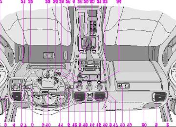
pg. 109 Engine compartment
Engine compartment S40/V40
1 Power brakes 2 - 3 Brake fluid reservoir 4 Fusebox 5 Air cleaner 6 Battery 7 Oil dipstick, automatic transmission 8 Radiator 9 Oil filter 10 Charcoal canister (under fender) 11 Oil dipstick, engine 12 Generator 13 Windshield/headlight washer fluid reservoir 14 Power steering pump 15 Power steering fluid reservoir 16 Oil filler cap, engine 17 Expansion tank, coolant 18 Windshield wiper motor 19 Chassis number
A ABS B Air conditioning compressor C Condenser, air conditioning D Accumulator, air conditioning
WARNING! The coolant fan may start or continue to operate (for up to 6 minutes) after the engine has been switched off.
pg. 110 Fuel/emissions systems
Fuel system
The fuel system is allelectronic and is microprocessorcontrolled. It can continually compensate for variation in engine load, speed and temperature to give the best economy and power. A mass air flow sensor measures the inducted air. In this way the system can make instantaneous adjustments for changes in air temperature or density, thus always assuring the best economy with the lowest possible exhaust emissions.
Heated oxygen sensor
This is an emission control system designed to reduce emissions and improve fuel economy. The heated oxygen sensor monitors the composition of the exhaust gases leaving the engine. The exhaust gas analysis is fed into an electronic module. This adjusts the airfuel ratio to provide optimum conditions for combustion and efficient reduction of the three major pollutants (hydrocarbons, carbon monoxide and oxides of nitrogen (NOx) by a threeway catalytic converter.
Secondary Air Injection (certain models)
This system adds air to the hot exhaust gases as they are expelled from the engine. This causes a secondary combustion of residual hydrocarbons and carbon monoxide, resulting in lower emissions levels in the exhaust gases.
Crankcase ventilation
The engine is provided with positive crankcase ventilation which prevents crankcase gases from being released into the atmosphere. Instead, the crankcase gases are admitted to the intake manifold and cylinders.
Evaporative control system
The car is equipped with an evaporative control system which prevents gasoline vapor from being released into the atmosphere.
The system consists of a fuel tank with filler pipe and cap, a rollover valve, a Fill Limit Vent Valve (FLVV), vapor vent lines, a charcoal canister, a purge line, a purge control valve and engine connections.
In addition, there is a pressure sensor connected to the fuel tank and a filter-protected Canister Close Valve (CCV) on the atmospheric side of the canister, for system diagnosis.
The gasoline vapor is channeled through the rollover valve and the FLVV via the vapor vent lines into the charcoal canister, where it is stored. When the engine is started, the gasoline vapor is drawn from the charcoal canister to the engine's air intake system and into the combustion process.
NOTE:
· If the fuel filler cap is not closed tightly or if the engine is running when the car is refueled, the Malfunction Indicator Lamp may indicate a fault.
· During a transitional period, a small number of service stations may still have fuel nozzles that are not compatible with the fuel filler neck on cars equipped with the evaporative control system (ORVR) mandated by the U.S. Environmental Protection Agency and the California Air Resources Board. If you experience difficulties in refueling your vehicle, please ask the gas station attendant for assistance.
CAUTION:
Fuel must not be siphoned from the fuel tank. This will damage the Evaporative control system.
Contents | Top of Page
2 0 0 0 VOLVO S & V 40
Chapter 9 - Specifications
pg. 119 Specifications
Specifications
This chapter contains facts and figures pertaining to the technical specifications of your car.
Oil/fluids specifications 120
Engine specifications 121
Cooling/fuel/distributor ignition systems 122
Front/rear suspensions 122
Transmission, Capacities, Vehicle loading 123
Electrical system/bulbs 124
Weights 125
Road assistance 126pg. 120 Oil/fluid specifications
Oil quality
Meeting API specification SJ, SJ/CF, or SJ/Energy Conserving.
For best fuel economy and engine protection, consult with your authorized Volvo retailer for recommended oils. Oil with a different quality rating may not provide adequate engine protection.
Synthetic oils complying with oil quality requirements are recommended for: driving in areas of sustained temperature extremes (hot or cold), when towing a trailer over long distances or for prolonged driving in mountainous areas.
Extra oil additives must not be used unless advised by an authorized Volvo retailer.
Viscosity (stable ambient temperatures):
Engine oil Automatic transmission fluid Power steering fluid Brake fluid
Quality: Meeting API specification SG or SH Quality: ATF Dexron III and Mercon Quality: ATF oil Quality: DOT 4+
Capacity (incl. filter): 5.7 US qts (5.4
liters) Capacity: 8 US qts. (7.6 liters) Capacity: 1.05 US qts. (1 liters) Capacity: 0.42 US qts. (0.4 liters)All specifications are subject to change without notice.
pg. 121 Engine
Engine
Liquidcooled gasoline, 4-cylinder, inline engine. Aluminum alloy cylinder block with castiron cylinder liners cast directly into the block. Aluminum alloy cylinder head with double overhead camshafts and separate intake and outlet channels.
Volvo B 4204 T2
160 hp at 5100 rpm (118 kw at 5100 rpm) 170 ft. lbs. at 1800-4800 rpm (230 Nm at 1800-4800 rpm)Engine lubrication is provided by an eccentric pump driven from the crankshaft. Fullflow type oil filter. Exhaust emission control is accomplished by multiport fuel injection, a heated oxygen sensor and a three-way catalytic converter. Designation: Output Max torque Number of cylinders 4
Bore Stroke Displacement Compression ratio Number of valves3.27" (83 mm) 3.54" (90 mm) 1.95 liters 9.0:1
16All specifications are subject to change without notice.
pg. 122 Specifications
Cooling system
Type: Positive pressure, closed system
Thermostat begins to open at 186° F (90° C)
Coolant: Volvo original coolant/antifreeze
Capacity: 6 US qts. (5.7 liters)
Fuel system
The engine is equipped with a multipoint fuel injection system.
Distributor ignition system
Firing order: 13-4-2
Distributor ignition setting: Not adjustable
Spark plugs: Champion RC8PYP or equivalent
Spark plug gap: 0.03" (0.75 mm)
Tightening torque: 18.4 ft. lbs. (25 Nm)
WARNING! The distributor ignition system operates at very high voltages. Special safety precautions must be followed to prevent injury. Always turn the ignition off when:
· Replacing distributor ignition components e.g. plugs, coil, etc.
· Do not touch any part of the distributor ignition system while the engine is running. This may result in unintended movements and body injury.
All specifications are subject to change without notice.
Replacing spark plugs
The spark plugs should be changed according to your service program in your Warranty booklet. However, city driving or fast highway driving may necessitate changing after 15,000 miles (24,000 km) of driving. When installing new plugs, be sure to fit the right type and use correct torque, see "Specifications". When changing the plugs, check that the suppressor connectors are in good condition. Cracked or damaged connectors should be replaced. When changing the spark plugs, clean the terminals and the rubber seals.
Front suspension
Spring strut suspension with integrated shock absorbers and control arms linked to the support frame. Powerassisted rack and pinion steering. Safety type steering column.
The alignment specifications apply to a car at curb weight (without passengers or cargo).
Toe-in measured on the wheel rims: 2,1 mm +- 0,7 mm
Toe-in measured on tire sides: 2,6 mm +- 0,8 mm
Rear suspension
Multilink individual rear wheel suspension with longitudinal support arms, double link arms and track rods.
Toe-in measured on the tire sides: 2,6 mm +- 0,8 mm
pg. 123 Specifications
Power transmission
Automatic transmission: AW 50-42
4speed automatic electronically controlled gearbox comprising a hydraulic torque converter with a lockup function; planetary gear, integrated final drive.
Operation via a floor mounted gear selector lever. Drive shafts with symmetrical joint location. Overdrive.
Final drive ratio 2.76:1
Reduction ratios
1st gear 3.61:1
2nd gear 2.06:1
3rd gear 1.37:1
4th gear 0.98:1
Reverse 3.96:1
Capacities
Fuel tank : 16 US gal. (60 liters)
Cooling system : 6 US qts. (5,7 liters)
Engine oil (incl. filter) : 5.7 US qts. ( 5.4 liters)
Automatic transmission : 8 US qts (7.6 liters)
Power steering fluid : 1.05 US qts (1 liters)
Washer fluid reservoir : 3.9 US qts. (3.75 liters)
Brake system : 0.42 US qts (0.4 liters)
Vehicle loading
The tires on your Volvo should perform to specifications at all normal loads when inflated as recommended on the tire information label. The label is located on the inside of the fuel filler flap. The label lists both tire and vehicle design limits. Do not load your car beyond the load limits indicated.
WARNING! Improperly inflated tires will reduce tire life, adversely affect vehicle handling and can possibly lead to failure resulting in loss of vehicle control without prior warning.
All specifications are subject to change without notice.
pg. 124 Specifications
Electrical system
12 Volt, negative ground.
Voltagecontrolled generator. Singlewire system with chassis and engine used as conductors.
Battery
Voltage: 12 Volt, capacity: 600 A/100 min
The battery contains corrosive and poisonous acids. It is of the utmost importance that old batteries are disposed of correctly. Your Volvo retailer can assist you in this matter.
Generator
Rated output: 120 A
Bulbs Bulb Headlights
US no.
Power
Socket No/bulbs
High beam 55W Low beam 55W
H7
H767
1156
1156
1156
H3Parking lights and Turn signals, front Turn signals, rear Side direction indicators - Tail lights Brake lights Backup lights Rear fog light Front fog lights License plate light (S40) - License plate light (V40) - Door step courtesy lights - Trunk light Vanity mirror lights Front courtesy lights Rear reading lights
3457NA 26/7W/30/2.2cp W2.5 16q 1156
21W/32cp 5W 5W/4cp 21W/32cp 21W/32cp 21W/32cp 55 W 5 W 5 W 10W 5 W 1.2 W 5 W 5 W
BA 15 s W 2.1x9.5 d BA 15 s BA 15 s BA 15 s BA 15 s PK22.5
W 2.1x9.5 d SV8.5
SV8.5
SV 8.5
SV5.5
SV5.5
W 2.1x9.5 dAll specifications are subject to change without notice.
pg. 125 Specifications
Dimensions S40/V40
Length S40/V40
Width S40/V40
Height S40/V40
Wheel base S40/V40
Track, front S40/V40
Track, rear Turning circle: S40/V40
Cargo capacity:176.4 in. (448 cm) 67.7 in. (172 cm) 55.5 in. (141 cm) 100.4 in. (255 cm) 57.1 in. (145 cm) 57.9 in. (147 cm) 34.1 ft. (11.2 m)
39.8 in. (101 cm) S40 (rear seat up) 68.5 in. (174 cm) S40 (rear seat down) 40.2 in. (102 cm) V40 (rear seat up) 68.9 in. (175 cm) V40 (rear seat down) Max width of load opening 27.6 in. (67 cm) Max height of load opening 20.1 in. (51 cm)
841 lbs (382 kg) 837 lbs (380 kg)
2093 lbs (950 kg) 2093 lbs (950 kg)
4180 lbs (1896 kg) 4340 lbs (1969 kg)
Weights Gross Vehicle Weight (GVW): S40
V40
Capacity Weight: S40
V40
Permissible axle weight, front: S40
V40
Permissible axle weight, rear: S40
V40
Permissible axle weight total: S40
V40
Curb weight: S40
V40
The max permissible axle loads or the gross vehicle weight must not be exceeded. Max roof load * Max trailer weight (w/o brakes) (with brakes) Max tongue weight **1100 lbs (500 kg) 2000 lbs (908 kg) 110 lbs (50 kg)
3921 lbs (1780 kg) 3964 lbs (1800 kg)
2996 lbs (1360 kg) 3040 lbs (1380 kg)
1885 lbs (856 kg) 1916 lbs (870 kg)
220 lbs (100 kg)
* For permanent roof racks, check the manufacturer's weight specifications.
** Please refer to section "Trailer towing"
WARNING! When adding accessories, equipment, luggage and other cargo to your vehicle, the total loaded weight capacity of the vehicle must not be exceeded.
All specifications are subject to change without notice.
pg. 126 Road Assistance
Your new Volvo comes with a four year road assistance program named ONCALL. Additional information, features, and benefits are described in a separate information package in your glove compartment.
If you have misplaced your package, dial:
In the U.S.A.
1-800-63-VOLVO (1-800-638-6586)
In Canada:
1-800-263-0475
Volvo supports Voluntary Mechanic Certification by the A.S.E. (pertains to the USA only). Certified mechanics have demonstrated a high degree of competence in specific areas. Besides passing exams each mechanic must also have worked in the field for two or more years before a certificate is issued. These professional mechanics are fully able to analyze vehicle problems and perform the necessary service procedures to keep your Volvo at peak operating condition.
All specifications are subject to change without notice.
Contents | Top of Page
2 0 0 0 VOLVO S & V 40
Chapter 10 - Audio systems
pg. 127 Audio systems
Audio systems
Even if you maintain your car in good running
This chapter describes the audio system in your car.
SC-813 128
SC-816 141
General information 157pg. 128 Audio system SC813
The following pages describe the use of your SC813 Cassette radio and CD remote control
1. On/off (push) 2. · Volume (turn) · Pause/Mute (push) · Balance (pull) 3. Active Sound Control 4. CD changer selector 5. · Tape mode selector · Tape direction selector PROG 6. Bass control 7. Treble control
8. Fader control 9. · Preset buttons - radio · CD-Disc No. selector 10. PROG - Reversing the tape 11. Dolby B NR button 12. Cassette eject 13. Not in use 14. Scan 15. Auto seek memory 16. · Radio - Seek tuning up/down · TP-Next/Previous song · CD-Next UP/Previous DOWN track 17. · Radio - Manual tuning · TP-fast forward/Rewind · CD-Music searchUP/DOWN 18. RND (random order play) button
19. Cassette slot 20. Display 21. Waveband selector (AM) 22. Waveband selectors (FM) 23. Anti-theft LED
TP = Applicable only in Tape Mode
CD = Applicable only when in CD mode and connected to a CD changer.
pg. 129 Anti-theft code
Anti-theft code
The radio features anti-theft circuitry. If the set is removed from the vehicle or if the battery power is disconnected, a special code must be entered to enable operation of the set.
Refer to the radio code card supplied with your vehicle or ask your Volvo retailer for the correct code.
When the car is parked with the ignition key removed, the anti-theft LED will flash. Anti-theft LED
To enter the code
After installation or when the set has been disconnected from power, the set displays "COdE" when it is switched on.
Enter the 4-digit code using the preset buttons.
If the correct code is entered, "on" is displayed and the set is ready to use.
If you enter an incorrect code you must enter the correct code again from the beginning.
Incorrect code
If an incorrect code has been entered "rPt" is displayed. Enter the correct code.
After three unsuccessful coding attempts the set will lock and remain locked for two hours. "OFF" is displayed.
During this waiting period:
· the battery must be connected
· the ignition key must be turned to position I
· the unit must be turned on
Make sure the headlights are turned off to help prevent battery drain (please refer to page 26 for information on turning the headlights off).
Enter the code again once this time has elapsed.
pg. 130 Radio SC-813
A - On/off switch
Push the button to switch on the radio. Press the button slightly longer to turn the radio off.
B - Volume control
Turn the button clockwise to increase the volume. The volume control is electronic and has no end stop.
C - Waveband selector
The desired waveband is set by pressing one of the waveband selector buttons. The frequency and waveband is shown on the display.
NOTE: There are two FM wavebands and one AM waveband. This makes it possible to store 2 x 6 FM stations and 6
AM stations in memory.D - Setting frequency selection
The radio can be used in most parts of the world by changing the frequency selection intervals as follows:
Depress and hold preset button 5 and turn the radio ON. "USA" will flash on the display.
Each time button 5 is pressed, the frequency selection will change from "USA" to "AUS", etc. When the correct country name is displayed, wait 5 seconds and the radio will be ready for use.
E - Manual tuning
Press the left side tune button to tune to lower frequencies and the right side to tune to higher frequencies. The tuned frequency is displayed.
ST will be displayed to indicate stereo FM reception.
pg. 131 Radio SC-813
A - Seek tuning up/down
Press the left side tune button to tune to lower frequencies and the right side to tune to higher frequencies. The radio seeks the next audible station and stops there. If you wish to continue the seek tuning, press the tune button again.
B - Preset programming
1. Tune to the desired frequency.
2. Depress and hold a preset button. The audio will cut out. Keep the button depressed until the audio comes on again (approx. 2 seconds).
3. The frequency is now stored on this preset button.
C - Preset buttons
To select a pre-programed radio frequency, depress the preset button. The set frequency will be displayed.
pg. 132 Radio SC-813
A - Automatic programming (Auto)
Please note that this function will not interfere with pre-stored stations on buttons 1-6.
This function automatically seeks and stores up to 8 strong AM or FM stations.
This is especially useful when travelling in areas where radio stations are unfamiliar.
1. Depress and hold the "AUTO" button for at least 1 second. A number of strong stations (max. 8) on the chosen waveband are now automatically stored in the memory.
If there are no audible stations, "- - - -" is displayed.
B - Bass control
Adjust the bass by sliding the control up or down (up to increase, down to decrease).
A "detent" indicates "equalized" bass.
C - Treble control
Adjust the treble by sliding the control up or down (up to increase, down to decrease).
A "detent" indicates "equalized" treble.
2. Briefly press the "AUTO" button again to retreive one of the newly stored stations. A new station will be retrieved each time the button is pressed again.
pg. 133 Radio SC-813
A - Fader control
Adjust front/rear speaker balance by sliding the control up or down.
(Up to direct more sound to the front speakers, Down to direct more sound to the rear speakers).
The "detent" indicates "equalized" front /rear balance position.
B - Pause function
Press the "volume" knob to temporarily mute the sound. "PAUSE" is displayed.
C - Balance control
Pull out the "volume" knob and adjust the left/right balance by turning the knob counter- clockwise or clockwise.
D - Scan
Press this button to listen to each station for five seconds. Press it again to stop scanning. "Scan" will be displayed during scanning.
E - Active sound control (ASC)
The ASC function automatically adjusts the volume level of the audio system according to driving speed.
To deactivate ASC depress the "ASC" button.
To activate ASC, depress the "ASC" button until "ASC" is displayed.
Contents | Top of Page
2 0 0 0 VOLVO S & V 40
INDEX
pg. 158 - 160 Index
ABS Adjustable steering wheel Air conditioning Air mix Air vents Airbag (SIPS) Airbag (SRS) Alarm Anti-lock Brake System (ABS) Antifreeze Ashtrays Audio systems SC-813
SC-816
Automatic car washing Automatic transmission Driving mode selector Automatic transmission fluid Auxiliary socket Battery Battery maintenance Booster cushion Brake failure warning light Brake fluid Brake fluid warning light Brake system Bulb failure warning Bulbs21,69
32
35
33
33
41
21,69
71,115
31128
141
100
63,64,65,123
63
118,120
3171,124
117
10
20
114,120
20
69,70
20
124Cabin air filter Capacities Center head restraint Central locking button Chains - winter driving Changing a wheel Child booster cushion Child safety Child safety locks - rear doors Clock Concealed storage bin (wagon) Coolant - checking/changing Cooling system Cruise control Cup holders Cupholders Dimensions Doors and locks Drive belt Driving economy Dynamic Stability Assistance (DSA) ECC - Electronic Climate Control Electrical system Electrically operated driver's seat Electrically operated front seats Electrically operated sun roof Electrically operated windows Emergency towing Emergency warning flashers Emissions systems Engine Engine compartment Engine oil Engine oil - checking/changing Fog light - rear Folding rear seat (sedan) Front courtesy lights Front seats Front seats - heated Front suspension Fuel gauge
33
123
39
77
83
10
13
44
18
56
115
64,122
29
51
31,51125
39
115
60
2834,35
65,124
47
46
49
36
66
24
110
121
109
113,120
11222
53
48
45,46
30
122
18Fuel system Fuel tank cover - opening Fuses Gas tank cover - opening Generator Hand brake Handling Hazard warning flashers Heated front seats Heating Heating and air conditioning Hood Ignition switch Immobilizer (start inhibitor) Instruments Integrated booster cushion Jack Jack (sedan) Jump starting Keyless entry system Keylock Keys Label information Locking button - central Locks Long distance trips Lubrication Lumbar support Maintenance schedule Maintenance service Malfunction indicator lamp Manual transmission fluid Mirrors - rear/side view