- Download PDF Manual
-
385
4-3. Do-it-yourself maintenance
■Tire types
●Summer tires
Summer tires are high-speed performance tires best suited to highway driving under dry conditions. Since summer tires do not have the same traction performance as snow tires, summer tires are inadequate for driving on snow-covered or icy roads. For driving on snow-covered roads or icy roads, the use of snow tires is recommended. When installing snow tires, be sure to replace all four tires.
●All season tires
All season tires are designed to provide better traction in snow and to be adequate for driving in most winter conditions as well as for use year-round. All season tires, however, do not have adequate traction performance compared with snow tires in heavy or loose snow. Also, all season tires fall short in acceleration and handling performance compared with summer tires in highway driving.
●Snow tires
For driving on snow-covered roads or icy roads, we recommend using snow tires. If you need snow tires, select tires of the same size, con- struction and load capacity as the originally installed tires. Since your vehicle has radial tires as original equipment, make sure your snow tires also have radial construction. Do not install studded tires without first checking local regulations for possible restrictions. Snow tires should be installed on all wheels. (→P. 229) ■Initializing the tire pressure warning system
Initialize the system with the tire inflation pressure adjusted to the speci- fied level.
■If the tread on snow tires wears down below 0.16 in. (4 mm)
The effectiveness of the tires as snow tires is lost.
■If you press the tire pressure warning reset switch accidentally
If initialization is performed, adjust the tire inflation pressure to the speci- fied level and initialize the tire pressure warning system again.
386
4-3. Do-it-yourself maintenance
■When the initialization of the tire pressure warning system has
failed Initialization can be completed in a few minutes. However, in the follow- ing cases, the settings have not been recorded and the system will not operate properly. If repeated attempts to record tire inflation pressure settings are unsuccessful, have the vehicle inspected by your Toyota dealer. ●When operating the tire pressure warning reset switch, the tire pres-
sure warning light does not blink 3 times.
●After driving for a certain period of time since the initialization has been completed, the warning light comes on after blinking for 1
minute.■Tire pressure warning system certification
U.S.A. FCC ID: PAXPMVC010
This device complies with part 15 of the FCC Rules. Operation is subject to the following two conditions: (1) This device may not cause harmful interference, and (2) this device must accept any interference received, including interference that may cause undesired operation. FCC WARNING: Changes or modifications not expressly approved by the party responsi- ble for compliance could void the user's authority to operate the equip- ment. Canada Operation is subject to the following two conditions: (1) this device may not cause interference, and (2) this device must accept any interference, including interference that may cause undesired operation of the device.387
4-3. Do-it-yourself maintenance
CAUTION
■When inspecting or replacing tires
Observe the following precautions to prevent accidents. Failure to do so may cause damage to parts of the drive train as well as dangerous handling characteristics, which may lead to an accident resulting in death or serious injury. ●Do not mix tires of different makes, models or tread patterns.
Also, do not mix tires of remarkably different treadwear.
●Do not use tire sizes other than those recommended by Toyota. ●Do not mix differently constructed tires (radial, bias-belted or bias-ply
tires).
●Do not mix summer, all season and snow tires. ●Do not use tires that have been used on another vehicle.
Do not use tires if you do not know how they were used previously.
●Do not tow if your vehicle has a compact spare tire installed.
■When initializing the tire pressure warning system
Do not operate the tire pressure warning reset switch without first adjust- ing the tire inflation pressure to the specified level. Otherwise, the tire pressure warning light may not come on even if the tire inflation pressure is low, or it may come on when the tire inflation pressure is actually nor- mal.
388
4-3. Do-it-yourself maintenance
NOTICE
■Repairing or replacing tires, wheels, tire pressure warning valves,
transmitters and tire valve caps ●When removing or fitting the wheels, tires or the tire pressure warning valves and transmitters, contact your Toyota dealer as the tire pres- sure warning valves and transmitters may be damaged if not handled correctly.
●When replacing tire valve caps, do not use tire valve caps other than
those specified. The cap may become stuck.
■To avoid damage to the tire pressure warning valves and transmit-
ters When a tire is repaired with liquid sealants, the tire pressure warning valve and transmitter may not operate properly. If a liquid sealant is used, contact your Toyota dealer or other qualified service shop as soon as possible. Make sure to replace the tire pressure warning valve and transmitter when replacing the tire. (→P. 383)
■Driving on rough roads
Take particular care when driving on roads with loose surfaces or pot- holes. These conditions may cause losses in tire inflation pressure, reducing the cushioning ability of the tires. In addition, driving on rough roads may cause damage to the tires themselves, as well as the vehicle’s wheels and body.
■Low profile tires (vehicles with P195/50R16 tires)
Low profile tires may cause greater damage than usual to the tire wheel when sustaining impact from the road surface. Therefore, pay attention to the following: ●Be sure to use proper tire inflation pressure. If tires are under-inflated,
they may be damaged more severely.
●Avoid potholes, uneven pavement, curbs and other road hazards. Fail-
ure to do so may lead to severe tire and wheel damage.
■If tire inflation pressure of each tire becomes low while driving Do not continue driving, or your tires and/or wheels may be ruined.
389
4-3. Do-it-yourself maintenance Tire inflation pressure
■ Tire inflation pressure
The recommended cold tire inflation pressure and tire size are displayed on the tire and loading information label. (→P. 500)
390
4-3. Do-it-yourself maintenance
■ Inspection and adjustment procedure
Tire valve Tire pressure gauge
STEP 1
STEP 2
STEP 3
STEP 4
STEP 5
STEP 6
Remove the tire valve cap. Press the tip of the tire pressure gauge onto the tire valve. Read the pressure using the gauge gradations. If the tire inflation pressure is not at the recommended level, adjust the pressure. If you add too much air, press the center of the valve to deflate. After completing the tire inflation pressure measurement and adjustment, apply soapy water to the valve and check for leakage. Put the tire valve cap back on.
391
4-3. Do-it-yourself maintenance
■Tire inflation pressure check interval
You should check tire inflation pressure every two weeks, or at least once a month. Do not forget to check the spare.
■Effects of incorrect tire inflation pressure
Driving with incorrect tire inflation pressure may result in the following: ●Reduced fuel efficiency ●Reduced driving comfort and tire life ●Reduced safety ●Damage to the drive train If a tire needs frequent inflating, have it checked by your Toyota dealer.
■Instructions for checking tire inflation pressure
When checking tire inflation pressure, observe the following: ●Check only when the tires are cold.
If your vehicle has been parked for at least 3 hours or has not been driven for more than 1 mile or 1.5 km, you will get an accurate cold tire inflation pressure reading.
●Always use a tire pressure gauge.
The appearance of the tire can be misleading. In addition, tire infla- tion pressure that is even just a few pounds off can affect ride quality and handling.
●Do not reduce tire inflation pressure after driving. It is normal for tire
inflation pressure to be higher after driving. ●Never exceed the vehicle capacity weight.
Passengers and luggage weight should be placed so that the vehicle is balanced.
392
4-3. Do-it-yourself maintenance
CAUTION
■Proper inflation is critical to save tire performance
Keep your tires properly inflated. Otherwise, the following conditions may occur and result in an accident causing death or serious injury: ●Excessive wear ●Uneven wear ●Poor handling ●Possibility of blowouts resulting from overheated tires ●Poor sealing of the tire bead ●Wheel deformation and/or tire separation ●A greater possibility of tire damage from road hazards
NOTICE
■When inspecting and adjusting tire inflation pressure
Be sure to put the tire valve caps back on. Without the valve caps, dirt or moisture could get into the valve and cause air leakage, which could result in an accident. If the caps are lost, replace them as soon as possible.
393
4-3. Do-it-yourself maintenance Wheels
If a wheel is bent, cracked or heavily corroded, it should be replaced. Otherwise, the tire may separate from the wheel or cause a loss of handling control. ■ Wheel selection
When replacing wheels, care should be taken to ensure that they are equivalent to those removed in load capacity, diameter, rim width and inset*. Replacement wheels are available at your Toyota dealer. *: Conventionally referred to as “offset”. Toyota does not recommend using the following: ● Wheels of different sizes or types ● Used wheels ● Bent wheels that have been straightened
■ Aluminum wheel precautions (if equipped)
● Use only Toyota wheel nuts and wrenches designed for use
with your aluminum wheels.
● When rotating, repairing or changing your tires, check that the
wheel nuts are still tight after driving 1000 miles (1600 km).
● Be careful not to damage the aluminum wheels when using
tire chains.
● Use only Toyota genuine balance weights or equivalent and use a plastic or rubber hammer when balancing your wheels.
394
4-3. Do-it-yourself maintenance
■When replacing wheels
The wheels of your vehicle are equipped with tire pressure warning valves and transmitters that allow the tire pressure warning system to provide advance warning in the event of a loss in tire inflation pressure. Whenever wheels are replaced, tire pressure warning valves and trans- mitters must be installed. (→P. 383)
CAUTION
■When replacing wheels
●Do not use wheels that are a different size from those recommended in
the Owner’s Manual, as this may result in a loss of handling control.
●Never use an inner tube in a leaking wheel which is designed for a tubeless tire. Doing so may result in an accident, causing death or seri- ous injury.
■When installing the wheel nuts
Tapered portion
facing
tapered ends
●Be sure to install the wheel nuts with the inward. Installing the nuts with the tapered ends facing outward can cause the wheel to break and eventually cause the wheel to come off while driving, which could lead to an accident resulting in death or serious injury.
●Never use oil or grease on the wheel bolts or wheel nuts.
Oil and grease may cause the wheel nuts to be excessively tightened, leading to bolt or disc wheel damage. In addition, the oil or grease can cause the wheel nuts to loosen and the wheel may fall off, causing an accident and resulting in death or serious injury. Remove any oil or grease from the wheel bolts or wheel nuts.
395
4-3. Do-it-yourself maintenance
NOTICE
■Replacing tire pressure warning valves and transmitters
●Because tire repair or replacement may affect the tire pressure warn- ing valves and transmitters, make sure to have tires serviced by your Toyota dealer or other qualified service shop. In addition, make sure to purchase your tire pressure warning valves and transmitters at your Toyota dealer.
●Ensure that only genuine Toyota wheels are used on your vehicle.
Tire pressure warning valves and transmitters may not work properly with non-genuine wheels.
396
4-3. Do-it-yourself maintenance Air conditioning filter
The air conditioning filter must be changed regularly to maintain air conditioning efficiency. ■ Replacement method STEP 1
Vehicles without a smart key system Turn the engine switch to the “LOCK” position. Vehicles with a smart key system Turn the “POWER” switch off.
STEP 2
STEP 3
STEP 4
Open the glove box. Slide off the damper.
Push in each side of the glove box to disconnect the upper claws.
Pull out the glove box and dis- connect the lower claws.
397
4-3. Do-it-yourself maintenance
STEP 5
Remove the filter cover.
STEP 6
Remove the air conditioning filter and replace it with a new one.
The “↑UP” mark shown on the filter should be pointing up.
■Checking interval
Inspect and replace the air conditioning filter according to the maintenance schedule. In dusty areas or areas with heavy traffic flow, more frequent cleaning or early replacement may be required. (For scheduled maintenance information, please refer to the “Scheduled Maintenance Guide” or “Owner’s Manual Supplement”.)
■If air flow from the vents decreases dramatically
The filter may be clogged. Check the filter and replace if necessary.
NOTICE
■When using the air conditioning system
Make sure that a filter is always installed. Using the air conditioning system without a filter may cause damage to the system.
398
4-3. Do-it-yourself maintenance Wireless remote control/electronic key battery
Replace the battery with a new one if it is depleted. ■ You will need the following items:
● Flathead screwdriver ● Small flathead screwdriver ● Lithium battery CR2016 (vehicles without a smart key sys-
tem), or CR2032 (vehicles with a smart key system)
■ Replacing the battery (vehicles without a smart key system) STEP 1
Remove the cover.
To prevent damage to the key, cover the tip of the screwdriver with a rag.
STEP 2
Remove the module.
STEP 3
Open the case cover using a coin protected with tape etc. and remove the depleted bat- tery using a small flathead screwdriver.
Insert a new battery with the “+” terminal facing up.
399
4-3. Do-it-yourself maintenance
■ Replacing the battery (vehicles with a smart key system) STEP 1
Take out the mechanical key.
STEP 2
Remove the cover.
To prevent damage to the key, cover the tip of the screwdriver with a rag.
Remove the depleted battery using a small flathead screw- driver.
Insert a new battery with the “+” terminal facing up.
STEP 3
400
4-3. Do-it-yourself maintenance
■Use a CR2016 (vehicles without a smart key system) or CR2032 (vehi-
cles with a smart key system) lithium battery ●Batteries can be purchased at your Toyota dealer, local electrical appli-
ance shops or camera stores.
●Replace only with the same or equivalent type recommended by the
manufacturer.
●Dispose of used batteries according to local laws.
■If the key battery is depleted
The following symptoms may occur: ●The smart key system and wireless remote control will not function prop-
erly.
●The operational range will be reduced.
CAUTION
■Removed battery and other parts
These parts are small and if swallowed by a child, they can cause choking. Keep away from children. Failure to do so could result in death or serious injury.
NOTICE
■For normal operation after replacing the battery
Observe the following precautions to prevent accidents: ●Always work with dry hands.
Moisture may cause the battery to rust.
●Do not touch or move any other component inside the remote control. ●Do not bend either of the battery terminals.
401
4-3. Do-it-yourself maintenance Checking and replacing fuses
If any of the electrical components do not operate, a fuse may have blown. If this happens, check and replace the fuses as necessary. STEP 1
Vehicles without a smart key system Turn the engine switch off. Vehicles with a smart key system Turn the “POWER” switch off. Open the fuse box cover.
STEP 2
Engine compartment (type A fuse box)
Push the tab in and lift the lid off.
Engine compartment (type B fuse box)
Push the tab in and lift the lid off.
402
4-3. Do-it-yourself maintenance
Under the instrument panel
Remove the lid.
STEP 3
STEP 4
After a system failure, see “Fuse layout and amperage rat- ings” (→P. 406) for details about which fuse to check. Remove the fuse with the pull-out tool.
type A
Only removed using tool.
fuse can be the pullout
403
4-3. Do-it-yourself maintenance
STEP 5
Check if the fuse is blown.
Type A
Type B
Type C
404
Normal fuse Blown fuse Replace the blown fuse with a new fuse of an appropriate amperage rating. The amper- age rating can be found on the fuse box lid.
Normal fuse Blown fuse Replace the blown fuse with a new fuse of an appropriate amperage rating. The amper- age rating can be found on the fuse box lid.
Normal fuse Blown fuse Replace the blown fuse with a new fuse of an appropriate amperage rating. The amper- age rating can be found on the fuse box lid.
Type D
Type E
4-3. Do-it-yourself maintenance
Normal fuse Blown fuse Replace the blown fuse with a new fuse of an appropriate amperage rating. The amper- age rating can be found on the fuse box lid.
Normal fuse Blown fuse Contact your Toyota dealer.
405
4-3. Do-it-yourself maintenance
Fuse layout and amperage ratings
Engine compartment (type A fuse box)
Fuse
Ampere
Circuit
EFI-MAIN
HORN IG2
SPARE SPARE SPAREEFI NO.2
H-LP RH-LO
H-LP LH-LO
10 H-LP RH-HI
11 H-LP LH-HI
406
20 A
10 A 30 A 7.5 A 15 A 30 A
10 A
10 A
10 A
10 A
10 A
Multiport fuel injection system/ sequential multiport fuel injection system, EFI NO.2
Horn IG2 NO.2, METER, IGN Spare fuse Spare fuse Spare fuse Multiport fuel injection system/ sequential multiport fuel injection system Right-hand headlight (low beam) Left-hand headlight (low beam), gauge and meters Right-hand headlight (high beam) Left-hand headlight (high beam), gauge and meters4-3. Do-it-yourself maintenance
Fuse
Ampere
Circuit
12
IG2 NO.2
10 A
13 DOME
ECU-B NO.1
14
15 METER16
IGN
17 HAZ
18
ETCS
19
ABS NO.1
20
ENG W/PMP
21 H-LP-MAIN
22 H-LP CLN 23
24ABS MTR NO.1
P/I15 A
7.5 A 7.5 A
15 A
10 A
10 A
20 A
30 A
40 A
30 A 30 A 50 A
Multiport fuel injection system/ sequential multiport fuel injection system, steering switches, brake system, starter system, smart key system, occupant classification system, SRS airbag system Audio system, vehicle control and operation data recording, main body ECU, personal lights, lug- gage compartment light Main body ECU, smart key system Gauge and meters Multiport fuel injection system/ sequential multiport fuel injection system Emergency flashers Multiport fuel injection system/ sequential multiport fuel injection system Brake system Multiport fuel injection system/ sequential multiport fuel injection system H-LP LH-LO, H-LP RH-LO, H-LP LH-HI, H-LP RH-HI, daytime run- ning light system No circuit Brake system EFI-MAIN, HORN, IG2
407
4-3. Do-it-yourself maintenance
Fuse
Ampere
Circuit
25
ECU-B NO.2
7.5 A
26
27
2829
AM2
STRG LOCK ABS NO.2IGCT-MAIN
PTC HTR NO.1
PTC HTR NO.2
FAN PTC HTR NO.330 D/C CUT 31
32
33
34
35 DEF 36 DEICER 37
38
39
40
41
42 MIR HTRBATT FAN IGCT NO.2
IGCT NO.4
PCU IGCT NO.37.5 A 20 A 10 A
30 A
30 A 30 A 30 A 30 A 30 A 30 A 20 A 10 A 10 A 10 A 10 A 10 A 10 A
Air conditioning system, gauge and meters, occupant classifica- tion system, tire pressure warning system, starter system, smart key system, power door lock system Starter system Starter system Brake system IGCT NO.2, IGCT NO.3, IGCT NO.4, PCU, BATT FAN DOME, ECU-B NO.1
PTC heater PTC heater Electric cooling fan PTC heater MIR HTR, rear window defogger No circuit Battery cooling fan Hybrid system Hybrid system Hybrid system Hybrid system Outside rear view mirror defoggers408
4-3. Do-it-yourself maintenance
Engine compartment (type B fuse box)
Fuse DC/DC ABS MTR NO.2
HTR EPSAmpere 100 A 30 A 40 A 50 A
Circuit
Hybrid system Brake system Air conditioning system Electric power steering system
409
4-3. Do-it-yourself maintenance
Under the driver’s side instrument panel
Fuse
Ampere
Circuit
TAIL
PANEL DOOR R/R DOOR P
10 A
5 A 20 A 20 A
ECU-IG NO.1
5 A
ECU-IG NO.2
HTR-IG
GAUGE
9 WASHER 10 WIPER 11 WIPER RR 12
P/W
410
5 A
7.5 A
10 A
15 A 25 A 15 A 30 A
Parking lights, side marker lights, tail lights, license plate lights, front fog lights, gauge and meters Instrument panel lights Rear power window (right side) Front power window (right side) Rear window defogger, tire pres- sure warning system, main body ECU, brake system, vehicle stabil- ity control system, power door lock system, smart key system Electric power steering system Air conditioning system, PTC heater Back-up lights, audio system, shift lock control system, moon roof, vehicle control and operation data recording, vehicle proximity notifi- cation system Windshield wipers and washer Windshield wipers and washer Windshield wipers and washer Power window
4-3. Do-it-yourself maintenance
Fuse
Ampere
Circuit
13 DOOR R/L 14 DOOR D 15 CIG
16
ACC
17 D/L 18 OBD
19
STOP
20
21
2223
AM1
FOG FR S/ROOFS/HTR
20 A 20 A 15 A
5 A
25 A 7.5 A
7.5 A
7.5 A 15 A 25 A
15 A
Rear power window (left side) Front power window (left side) Power outlet Main body ECU, audio system, out- side rear view mirrors, shift lock control system Power door lock system On-board diagnosis Starter system, shift lock control system, vehicle proximity notifica- tion system, brake system, stop lights, high mounted stoplight Starter system Front fog lights Moon roof Seat heaters, air conditioning sys- tem
■After a fuse is replaced
●If the lights do not turn on even after the fuse has been replaced, a bulb
may need replacement. (→P. 413)
●If the replaced fuse blows again, have the vehicle inspected by your
Toyota dealer.
■If there is an overload in a circuit
The fuses are designed to blow, protecting the wiring harness from damage.
411
4-3. Do-it-yourself maintenance
CAUTION
■To prevent system breakdowns and vehicle fire
Observe the following precautions. Failure to do so may cause damage to the vehicle, and possibly a fire or injury. ●Never use a fuse of a higher amperage rating than that indicated, or use
any other object in place of a fuse.
●Always use a genuine Toyota fuse or equivalent.
Never replace a fuse with a wire, even as a temporary fix.
●Do not modify the fuses or fuse boxes. ■Fuse box near the power control unit
Never check or replace the fuses as there are high voltage parts and wiring near the fuse box. Doing so may cause electric shock, resulting in death or serious injury.
NOTICE
■Before replacing fuses
Have the cause of electrical overload determined and repaired by your Toyota dealer as soon as possible.
412
4-3. Do-it-yourself maintenance Light bulbs
You may replace the following bulbs by yourself. The difficulty level of replacement varies depending on the bulb. As there is a danger that components may be damaged, we recommend that replacement is carried out by your Toyota dealer. ■ Preparing for light bulb replacement
Check the wattage of the light bulb to be replaced. (→P. 501)
■ Front bulb locations
Parking lights
Front side marker lights
Front turn signal lights
Headlights (low beam)
Headlights (high beam) and daytime running lights
Front fog lights (if equipped)
413
4-3. Do-it-yourself maintenance
■ Rear bulb locations
Rear turn signal lights
Tail and rear side marker lights
Back-up lights
License plate lights
Replacing light bulbs
■ Headlights and daytime running lights STEP 1
Turn the bulb base counterclock- wise.
High beam and daytime run- ning lights (inside) Low beam (outside)
414
STEP 2
STEP 3
4-3. Do-it-yourself maintenance
Unplug pushing the lock release.
the connector while
High beam and daytime run- ning lights Low beam
Replace the light bulb, and install the bulb base.
Align the 3 tabs on the light bulb with the mounting, and insert.
STEP 4
Turn and secure the bulb base.
■ Front fog lights (if equipped) STEP 1
Shake the bulb base gently to check that it is not loose, turn the headlights and daytime running lights and headlight low beams on once and visually confirm that no light is leaking through the mount- ing.
Turn the steering wheel in the opposite direction of the light to be replaced.
Turn the steering wheel to a point that allows your hand to easily fit between the tire and fender liner.
415
4-3. Do-it-yourself maintenance
STEP 2
Partly remove the fender liner.
STEP 3
STEP 4
Unplug pushing the lock release.
the connector while
Turn the bulb base counterclock- wise.
STEP 5
Install a new bulb.
Align the 3 tabs on the light bulb with the mounting, and insert.
416
STEP 6
4-3. Do-it-yourself maintenance
Turn and secure the bulb. Install the connector.
Shake the bulb base gently to check that it is not loose, turn the front fog light on once and visu- ally confirm that no light is leaking through the mounting.
STEP 7
STEP 5When installing the fender liner, install by conducting with the directions reversed.
STEP 7
STEP 2
STEP 5■ Parking lights STEP 1
Unplug pushing the lock release.
the connector while
417
4-3. Do-it-yourself maintenance
STEP 2
Turn the bulb base counterclock- wise.
STEP 3
Remove the light bulb.
When installing, reverse the steps listed.
STEP 4
■ Front side marker lights STEP 1Turn the steering wheel in the opposite direction of the light to be replaced.
Turn the steering wheel to a point that allows your hand to easily fit between the tire and fender liner.
418
4-3. Do-it-yourself maintenance
STEP 2
Remove the clips.
STEP 3
Partly remove the fender liner.
STEP 4
Turn the bulb base counterclock- wise.
STEP 5
Remove the light bulb.
419
4-3. Do-it-yourself maintenance
STEP 6
When installing the light bulb and bulb base, reverse the steps listed.
STEP 7
Installing the clips.
■ Front turn signal lights STEP 1
Partly remove the fender liner as described in STEP 2
of “Front fog lights”. (→P. 415)
STEP 1
and
STEP 2
Turn the bulb base counterclock- wise.
STEP 3
Remove the light bulb.
STEP 4
When installing, reverse the steps listed.
420
4-3. Do-it-yourself maintenance
■ Rear turn signal lights, tail and rear side marker lights, and
back-up lights
STEP 1
STEP 2
Open the back door and remove the bolts. Pull the lamp assembly straight back to disengage the clip and 2 pins.
Where the clip attaches Pin
Turn the bulb base counterclock- wise.
Rear turn signal light Tail and rear side marker light Back-up light
421
4-3. Do-it-yourself maintenance
STEP 3
Remove the light bulb. Rear turn signal light Tail and rear side marker light Back-up light
When installing, reverse the steps listed.
STEP 4
■ License plate light STEP 1Remove the cover.
Insert a properly sized screw- driver into the hole of the cover, and pry off the cover as shown in the illustration. To prevent damaging the vehicle, wrap the tip of the screwdriver with tape.
STEP 2
Remove the light bulb.
STEP 3
When installing, reverse the steps listed.
422
4-3. Do-it-yourself maintenance
■ Lights other than the above
If any of the lights listed below has burnt out, have it replaced by your Toyota dealer. ● Side turn signal lights ● Stop lights ● High mounted stoplight
■LED light bulbs
The stop lights and high mounted stoplight consist of a number of LEDs. If any of the LEDs burn out, take your vehicle to your Toyota dealer to have the light replaced.
■Condensation build-up on the inside of the lens
Temporary condensation build-up on the inside of the headlight lens does not indicate a malfunction. Contact your Toyota dealer for more information in the following situations: ●Large drops of water have built up on the inside of the lens. ●Water has built up inside the headlight.
423
4-3. Do-it-yourself maintenance
CAUTION
■Replacing light bulbs
●Turn off the lights. Do not attempt to replace the bulb immediately after
turning off the lights. The bulbs become very hot and may cause burns.
●Do not touch the glass portion of the light bulb with bare hands. Hold the
bulb by the plastic or metal portion. If the bulb is scratched or dropped, it may blow out or crack.
●Fully install light bulbs and any parts used to secure them. Failure to do so may result in heat damage, fire, or water entering the headlight unit. This may damage the headlights or cause condensation to build up on the lens.
■To prevent damage or fire
Make sure bulbs are fully seated and locked.
424
5-1. Essential information Emergency flashers
The emergency flashers are used to warn other drivers when the vehicle has to be stopped in the road due to a breakdown, etc.
Press the switch.
All the turn signal lights will flash. To turn them off, press the switch once again.
■Emergency flashers
If the emergency flashers are used for a long time while the hybrid system is not operating (while the “READY” indicator is not illuminated), the 12-volt battery may discharge.
426
5-1. Essential information If your vehicle needs to be towed
If towing is necessary, we recommend having your vehicle towed by your Toyota dealer or a commercial towing service, using a lift-type truck or flatbed truck. Use a safety chain system for all towing, and abide by all state/pro- vincial and local laws.
Before towing
The following may indicate a problem with your hybrid transmission. Contact your Toyota dealer before towing. ● The hybrid system is operating but the vehicle will not move. ● The vehicle makes an abnormal sound.
Emergency towing
If a tow truck is not available in an emergency, your vehicle may be temporarily towed using a cable or chain secured to the emergency towing eyelet. This should only be attempted on hard surfaced roads for short distances at under 18 mph (30
km/h). A driver must be in the vehicle to steer and operate the brakes. The vehicle’s wheels, drive train, axles, steering and brakes must be in good condition.427
Push the eyelet cover and then open it.
Insert the towing eyelet into the hole and tighten partially by hand.
Tighten down the towing eyelet securely using a wheel nut wrench.
5-1. Essential information
Installing towing eyelet
STEP 1
STEP 2
STEP 3
428
Towing with a sling-type truck
5-1. Essential information
Do not tow with a sling-type truck to prevent body damage.
Towing with a wheel-lift type truck
From the front
Release the parking brake.
From the rear
Use a towing dolly under the front wheels.
429
5-1. Essential information
Using a flatbed truck
■Before emergency towing
If you use chains or cables to tie down your vehicle, the angles shaded in black must be 45°. Do not overly tighten the tie downs or the vehicle may be damaged.
STEP 1
Vehicles without a smart key system Turn the engine switch to the “ACC” (hybrid system off) or “ON” (hybrid system operating) position. Vehicles with a smart key system Turn the “POWER” switch to ACCESSORY (hybrid system off) or ON (hybrid system operating) mode. Shift the shift lever to N. Release the parking brake. ■Emergency towing eyelet location
STEP 2
STEP 3
→P. 459
430
5-1. Essential information
CAUTION
■Caution while towing
●Use extreme caution when towing the vehicle.
Avoid sudden starts or erratic driving maneuvers which place excessive stress on the emergency towing eyelet and the cables or chains. Always be cautious of the surroundings and other vehicles while towing.
●Do not turn the engine switch off (vehicles without a smart key system) or
the “POWER” switch off (vehicles with a smart key system). This may lead to accidents because the steering wheel will be locked and you will not be able to operate the steering wheel.
●If the hybrid system is off, the power assist for the brakes and steering will
not function, making steering and braking more difficult.
■Installing towing eyelet to the vehicle
Make sure that towing eyelet is installed securely. If not securely installed, towing eyelet may come loose during towing. This may lead to accidents that cause serious injury or even death.
NOTICE
■To prevent causing serious damage to the transmission when towing
using a wheel-lift type truck Never tow this vehicle from the rear with the front wheels on the ground.
■To prevent damage to the vehicle when towing using a wheel-lift type
truck When raising the vehicle, ensure adequate ground clearance for towing at the opposite end of the raised vehicle. Without adequate clearance, the vehicle could be damaged while being towed.
■To prevent body damage when towing with a sling-type truck
Do not tow with a sling-type truck, either from the front or rear.
■To prevent causing serious damage to the transmission in emergency
towing Never tow a vehicle from the rear with four wheels on the ground. This may cause serious damage to the transmission.
431
5-1. Essential information If you think something is wrong
If you notice any of the following symptoms, your vehicle probably needs adjustment or repair. Contact your Toyota dealer as soon as possible. ■ Visible symptoms
● Fluid leaks under the vehicle
(Water dripping from the air conditioning after use is normal.)
● Flat-looking tires or uneven tire wear
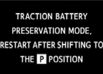
●
is shown on the multi-information display
■ Audible symptoms
● Changes in exhaust sound ● Excessive tire squeal when cornering ● Strange noises related to the suspension system ● Pinging or other noises related to the hybrid system
■ Operational symptoms
● Engine missing, stumbling or running roughly ● Appreciable loss of power ● Vehicle pulls heavily to one side when braking ● Vehicle pulls heavily to one side when driving on a level road ● Loss of brake effectiveness, spongy feeling, pedal almost
touches the floor
432
5-2. Steps to take in an emergency If a warning light turns on or a warning buzzer sounds
Calmly perform the following actions if any of the warning lights comes on or flashes. If a light comes on or flashes, but then goes off, this does not necessarily indicate a malfunction in the system. However, if this continues to occur, have the vehicle inspected by your Toyota dealer.
Stop the vehicle immediately. Continuing to drive the vehicle may be dangerous.
The following warning indicates a possible problem in the brake sys- tem. Immediately stop the vehicle in a safe place and contact your Toyota dealer.
Warning light
Warning light/Details
(U.S.A.)
(Canada)
Brake system warning light in red (warning buzzer)* • Low brake fluid • Malfunction in the brake system This light also comes on when the parking brake is not released. If the light turns off after the parking brake is fully released the system is operating normally.
*: Brake system warning buzzer:
When there is a possible problem that could affect braking performance, the warning light will come on and a warning buzzer will sound. Parking brake engaged warning buzzer: →P. 446
433
5-2. Steps to take in an emergency
Stop the vehicle immediately.
The following warning indicates the possibility of damage to the vehi- cle that may lead to an accident. Immediately stop the vehicle in a safe place and contact your Toyota dealer.
Warning light
Warning light/Details
Charging system warning light Indicates a malfunction in the vehicle's charging sys- tem
Have the vehicle inspected by your Toyota dealer immediately.
Failure to investigate the cause of the following warnings may lead to the system operating abnormally and possibly cause an accident. Have the vehicle inspected by your Toyota dealer immediately.
Warning light
Warning light/Details
(U.S.A.)
(Canada)
Malfunction indicator lamp Indicates a malfunction in: • The hybrid system; • The electronic engine control system; or • The electronic throttle control system
SRS warning light Indicates a malfunction in: • The SRS airbag system; • The front passenger occupant classification system; or • The seat belt pretensioner system
(U.S.A.)
(Canada)
ABS warning light Indicates a malfunction in: • The ABS; or • The brake assist system
434
5-2. Steps to take in an emergency
Warning light
Warning light/Details
(Comes on)
Electric power steering system warning light (warn- ing buzzer) Indicates a malfunction in the EPS (Electric Power Steering) system Slip indicator light Indicates a malfunction in: • Vehicle stability control; • Traction control; or • Hill-start assist control Brake system warning light in yellow Indicates a malfunction in: • The regenerative brake system; or • The electronically controlled brake system
Follow the correction procedures.
After taking the specified steps to correct the suspected problem, check that the warning light goes off.
Warning light
(Flashes)
Warning light/Details Low fuel level warning light Remaining fuel is low When the remaining fuel is approximately 1.2 gal. (4.7 L, 1.0 Imp. gal.) or less, a buzzer sounds and the lowest segment of the fuel gauge flashes
Correction procedure
Refuel the vehicle.