- Download PDF Manual
-
the light illuminates steadily after blinking for approximately one minute, promptly contact a SUBARU dealer to have the system inspected.
If
immedi-
& Tire inspection Check on a daily basis that the tires are free from serious damage, nails, and stones. At the same time, check the tires for abnormal wear. Contact your SUBARU dealer ately if you find any problem. NOTE . When the wheels and tires strike curbs or are subjected to harsh treat- ment as when the vehicle is driven on a rough surface, they can suffer damage that cannot be seen with the naked eye. This type of damage does not become evident until time has passed. Try not to drive over curbs, potholes or on other rough surfaces. If doing so is unavoidable, keep the vehicle’s speed down to a walking pace or less, and approach the curbs as squarely as possible. Also, make sure the tires are not pressed against the curb when you park the vehicle.
北米Model "A8130BE-B" EDITED: 2007/ 7/ 25
Black plate (323,1)
Maintenance and service 11-33
trollability and ride comfort, and they cause the tires to wear abnormally. . Correct evenly)
tire pressure (tread worn
Roadholding is good, and steering is responsive. Rolling resistance is low, so fuel consumption is also lower.
11
. If you feel unusual vibration while driving or find it difficult to steer the vehicle in a straight line, one of the tires and/or wheels may be damaged. Drive slowly to the nearest authorized SUBARU dealer and have the vehicle inspected.
& Tire pressures and wear tire pressures Maintaining the correct helps to maximize the tires’ service lives and is essential for good running perfor- mance. Check and, if necessary, adjust the pressure of each tire (including the spare) at least once a month (for example, during a fuel stop) and before any long journey.
the tire pressures to the values shown on the tire placard. The tire placard is located on the door pillar on the driver’s side.
Driving even a short distance warms up the tires and increases the tire pressures. Also, the tire pressures are affected by the outside temperature. It is best to check tire pressure outdoors before driving the vehicle.
When a tire becomes warm, the air inside it expands, causing the tire pressure to increase. Be careful not to mistakenly release air from a warm tire to reduce its pressure. NOTE . The air pressure in a tire increases by approximately 4.3 psi (30 kPa, 0.3
kgf/cm2) when the tire becomes warm. . The tires are considered cold when the vehicle has been parked for at least three hours or has been driven less than one mile (1.6 km).WARNING
Do not let air out of warm tires to adjust pressure. Doing so will result in low tire pressure.
Check the tire pressures when the tires are cold. Use a pressure gauge to adjust
Incorrect tire pressures detract from con-
– CONTINUED –
北米Model "A8130BE-B" EDITED: 2007/ 7/ 25
11-34 Maintenance and service
. Abnormally low tire pressure (tread worn at shoulders)
. Abnormally high tire pressure (tread worn in center)
Rolling resistance is high, so fuel con- sumption is also higher.
is poor. Also,
the tire Ride comfort magnifies the effects of road-surface bumps and dips, possibly resulting in vehicle damage.
If the tire placard shows tire pressures for the vehicle when fully loaded and for the vehicle when towing a trailer, adjust the tire pressures to the values that match current loading conditions.
WARNING
Driving at high speeds with exces- sively low tire pressures can cause the tires to deform severely and to rapidly become hot. A sharp in- crease in temperature could cause
Black plate (324,1)
tread separation, and destruction of the tires. The resulting loss of vehicle control could lead to an accident.
that
& Wheel balance Each wheel was correctly balanced when your vehicle was new, but the wheels will become unbalanced as the tires become worn during use. Wheel imbalance causes the steering wheel to vibrate slightly at certain vehicle speeds and detracts from the vehicle’s straight-line stability. It can also cause steering and suspension sys- tem problems and abnormal tire wear. If you suspect the wheels are not correctly balanced, have them checked and adjusted by your SUBARU dealer. Also have them adjusted after tire repairs and after tire rotation. NOTE Loss of correct wheel alignment* causes the tires to wear on one side and reduces the vehicle’s running stability. Contact your SUBARU dealer if you notice abnormal tire wear. *: The suspension system is designed to hold each wheel at a certain alignment (relative to the other wheels and to the road) for optimum straight-line stability and cornering perfor-
北米Model "A8130BE-B" EDITED: 2007/ 7/ 25
Black plate (325,1)
Maintenance and service 11-35
mance.
& Wear indicators
a tire in this condition, driving at high speeds in wet weather can cause the vehicle to hydroplane. The resulting loss of vehicle control can lead to an accident.
When you install a tire that has the tire rotation direction mark, install the tire with the direction mark facing forward.
& Tire rotation
NOTE For safety, inspect tire tread regularly and replace the tires before their tread wear indicators become visible.
& Tire rotation direction mark
1) New tread 2) Worn tread 3)
Tread wear indicator
Each tire incorporates a tread wear indicator, which becomes visible when the depth of the tread grooves decreases to 0.063 in (1.6 mm). A tire must be replaced when the tread wear indicator appears as a solid band across the tread.
WARNING
When a tire’s tread wear indicator becomes visible, the tire is worn beyond the acceptable limit and must be replaced immediately. With
Example of tire rotation direction mark 1)
Front
the tire has the rotation direction the tire rotation direction
If specification, mark is placed on its sidewall.
Vehicles equipped with 4 non-unidirec- tional tires 1)
Front
11
– CONTINUED –
北米Model "A8130BE-B" EDITED: 2007/ 7/ 25
11-36 Maintenance and service
Vehicles equipped with unidirectional tires 1)
Front
Tire wear varies from wheel to wheel. To maximize the life of each tire and ensure that the tires wear uniformly, it is best to rotate the tires every 7,500 miles (12,000
km). Move the tires to the positions shown in the illustration each time they are rotated. Replace any damaged or unevenly worn tire at tire rotation, adjust the tire pressures and make sure the wheel nuts are correctly tightened.rotation. After
the time of
After driving approximately 600 miles (1,000 km), check the wheel nuts again and retighten any nut that has become loose.
Black plate (326,1)
& Tire replacement The wheels and tires are important and integral parts of your vehicle’s design; they cannot be changed arbitrarily. The tires fitted as standard equipment are optimally matched to the characteristics of the vehicle and were selected to give the best possible combination of running performance, ride comfort, and service life. It is essential for every tire to have a size and construction matching those shown on the tire placard and to have a speed symbol and load index matching those shown on the tire placard.
Using tires of a non-specified size detracts from controllability, ride comfort, braking performance, speedometer accuracy and odometer accuracy. It also creates incor- rect body-to-tire clearances and inappro- priately changes the vehicle’s ground clearance.
All four tires must be the same in terms of manufacturer, brand (tread pattern), con- struction, and size. You are advised to replace the tires with new ones that are identical to those fitted as standard equip- ment.
For safe vehicle operation, SUBARU recommends replacing all tires at the same time.
four
WARNING
. All four tires must be the same in terms of manufacturer, brand (tread pattern), construction, de- gree of wear, speed symbol, load index and size. Mixing tires of different types, sizes or degrees of wear can result in damage to vehicle’s power train. Use of different types or sizes of tires can also dangerously reduce controllability and braking per- formance and can lead to an accident.
. Use only radial tires. Do not use radial tires together with belted bias tires and/or bias-ply tires. Doing so can dangerously re- duce controllability, resulting in an accident.
& Wheel replacement When replacing wheels due, for example, to damage, make sure the replacement wheels match the specifications of the wheels that are fitted as standard equip- ment. Replacement wheels are available from SUBARU dealers.
北米Model "A8130BE-B" EDITED: 2007/ 7/ 25
WARNING
Use only those wheels that are specified for your vehicle. Wheels not meeting specifications could interfere with brake caliper opera- tion and may cause the tires to rub against the wheel well housing dur- ing turns. The resulting loss of vehicle control could lead to an accident.
Aluminum wheels (if equipped)
Aluminum wheels can be scratched and damaged easily. Handle them carefully to maintain their appearance, performance, and safety. . When any of the wheels is removed and replaced for tire rotation or to change a flat, always check the tightness of the wheel nuts after driving approximately 600
miles (1,000 km). If any nut is loose, tighten it to the specified torque. . Never apply oil to the threaded parts, wheel nuts, or the wheel. . Never let the wheel rub against sharp protrusions or curbs. . Be sure to fit tire chains on uniformly and completely around the tire, otherwise the chains may scratch the wheel. . When wheel nuts, balance weights, or the center cap is replaced, be sure to replace them with genuine SUBARU parts designed for aluminum wheels.tapered surface of
Black plate (327,1)
Maintenance and service 11-37
Windshield washer fluid
CAUTION
Never use engine coolant as washer fluid because it could cause paint damage.
If you spray washer fluid on the windshield but the supply of washer fluid appears to diminish, check the level of washer fluid in the tank.
11
– CONTINUED –
北米Model "A8130BE-B" EDITED: 2007/ 7/ 25
11-38 Maintenance and service
Washer fluid level gauge
Remove the washer tank filler cap, then check the fluid level indicated by the level gauge (attached to the inside of the cap). is near the “Low” mark, add If the level fluid until it reaches the “Hi” level on the
level gauge or the “Full” mark on the tank. Use windshield washer fluid. If windshield washer fluid is unavailable use clean water. In areas where water freezes in winter, use an anti-freeze type windshield washer fluid. SUBARU Windshield Washer Fluid contains 58.5% methyl alcohol and 41.5% surfactant, by volume. Its freezing tem- perature varies according to how much it is diluted, as indicated in the following table.
Washer Fluid Concentration
30%
50%
100%
Freezing
Temperature 10.48F (−128C) −48F (−208C) −498F (−458C)
CAUTION
Never use engine coolant as washer fluid because it could cause paint damage.
In order to prevent freezing of washer fluid, check the freezing temperatures in the table above when adjusting the fluid concentration to the outside temperature. If you fill the reservoir tank with a fluid with a different concentration from the one
Black plate (328,1)
used previously, purge the old fluid from the piping between the reservoir tank and washer nozzles by operating the washer for a certain period of time. Otherwise, if the concentration of the fluid remaining in the piping is too low for the outside temperature, it may freeze and block the nozzles.
CAUTION
Adjust the washer fluid concentra- tion appropriately for the outside temperature. If the concentration is inappropriate, sprayed washer fluid may freeze on the windshield and obstruct your view, and the fluid may freeze in the reservoir tank.
北米Model "A8130BE-B" EDITED: 2007/ 7/ 25
Replacement of wiper blades
Grease, wax, insects, or other material on the windshield or the wiper blade results in jerky wiper operation and streaking on the glass. If you cannot remove the streaks after operating the windshield washer or if the wiper operation is jerky, clean the outer surface of the windshield (or rear window) and the wiper blades using a sponge or soft cloth with a neutral detergent or mild abrasive cleaner. After cleaning, rinse the windshield and wiper blades with clean water. The windshield is clean if beads do not form when you rinse the windshield with water.
CAUTION
Do not clean the wiper blades with gasoline or a solvent, such as paint thinner or benzene. This will cause deterioration of the wiper blades.
If you cannot eliminate the streaking even after following this method, replace the wiper blades using the following proce- dures:
Black plate (329,1)
Maintenance and service 11-39
& Windshield wiper blades 1. Raise the wiper arm off the windshield.
1) Stopper
2. Remove the wiper blade assembly by holding its pivot area and pushing it in the direction shown by the arrow while de- pressing the wiper blade stopper.
1) Metal support
3. Grasp the locked end of the blade rubber assembly and pull it firmly until the stoppers on the rubber are free of the metal support.
11
– CONTINUED –
北米Model "A8130BE-B" EDITED: 2007/ 7/ 25
Black plate (330,1)
11-40 Maintenance and service
with the grooves in the rubber and slide the blade rubber assembly into the metal support until it locks.
& Rear window wiper blade 1. Raise the wiper arm off window.
the rear
1) Metal spines
4. If the new blade rubber is not provided with two metal spines, remove the metal spines from the old blade rubber and install them in the new blade rubber.
5. Align the claws of the metal support
2. Turn the wiper blade assembly coun- terclockwise.
1) Stopper
Be sure to position the claws at the end of the metal support between the stoppers on the rubber as shown. If the rubber is not retained properly, the wiper blade may scratch the windshield. 6. Install the wiper blade assembly to the wiper arm. Make sure that it locks in place. 7. Lower the wiper arm.
北米Model "A8130BE-B" EDITED: 2007/ 7/ 25
Black plate (331,1)
Maintenance and service 11-41
install them in the new blade rubber.
3. Having turned the wiper blade assem- bly to the angle shown in the illustration, pull the arrow to remove it from the wiper arm.
in the direction of
it
5. Pull the blade rubber assembly out of the plastic support.
7. Align the claws of the plastic support with the grooves in the blade rubber assembly, then slide the blade rubber assembly into place.
1) Plastic support
4. Pull out the end of the blade rubber assembly to unlock it from the plastic support.
11
1) Metal spines
6. If the new blade rubber is not provided with two metal spines, remove the metal spines from the old blade rubber and
Securely lock the end of
the plastic
– CONTINUED –
北米Model "A8130BE-B" EDITED: 2007/ 7/ 25
11-42 Maintenance and service
support as shown in the illustration. If the rubber is not retained properly, the wiper may scratch the rear window glass. 8. Install the wiper blade assembly to the wiper arm. Make sure that it locks in place. 9. Lower the wiper arm.
Battery
WARNING
. Before beginning work on or near any battery, be sure to extinguish all cigarettes, matches, and light- ers. Never expose a battery to an open flame or electric sparks. Batteries give off a gas which is highly flammable and explosive. . For safety, in case an explosion does occur, wear eye protection or shield your eyes when work- ing near any battery. Never lean over a battery.
. Do not let battery fluid contact eyes, skin, fabrics, or paint be- cause battery fluid is a corrosive acid. If battery fluid gets on your skin or in your eyes, immediately flush the area with water thor- oughly. Seek medical help imme- diately if acid has entered the eyes. If battery fluid is accidentally swallowed, immediately drink a large amount of milk or water, and seek medical attention im- mediately.
. To lessen the risk of sparks,
Black plate (332,1)
remove rings, metal watchbands, and other metal jewelry. Never allow metal tools to contact the positive battery terminal and any- thing connected to it WHILE you are at the same time in contact with any other metallic portion of the vehicle because a short cir- cuit will result.
. Keep everyone including children
away from the battery.
. Charge the battery in a well-
ventilated area.
. Battery posts, terminals and re- lated accessories contain lead and lead compounds, chemicals known to the State of California to cause cancer and reproductive harm. Batteries also contain other chemicals known to the State of California to cause can- cer. Wash hands after handling.
CAUTION
Never use more than 10 amperes when charging the battery because it will shorten battery life.
北米Model "A8130BE-B" EDITED: 2007/ 7/ 25
Black plate (333,1)
Maintenance and service 11-43
Fuses
CAUTION
Never replace a fuse with one hav- ing a higher rating or with material other than a fuse because serious damage or a fire could result.
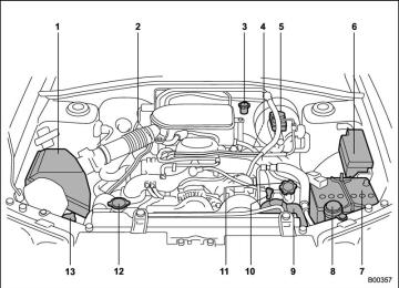
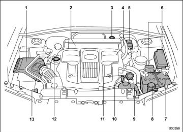
The fuses are designed to melt during an overload to prevent damage to the wiring harness and electrical equipment. The fuses are located in two fuse boxes.
1) Cap 2) Upper level Lower level 3)
It is unnecessary to periodically check the battery fluid level or periodically refill with distilled water. However, if the battery fluid level is below the lower level, remove the cap. Fill to the upper level with distilled water.
The other one is housed in the engine compartment.
11
One is located under the instrument panel behind the cover on the driver’s seat side. To remove the cover, pull it out.
1) Fuse puller 2) Spare fuse
The fuse puller and spare fuses are stored in the main fuse box cover in the engine – CONTINUED –
北米Model "A8130BE-B" EDITED: 2007/ 7/ 25
11-44 Maintenance and service
compartment.
1) Good 2) Blown
inspect
If any lights, accessories or other electrical controls do not operate, the corresponding fuse. If a fuse has blown, replace it. 1. Turn the ignition switch to the “LOCK” position and turn off all electrical acces- sories. 2. Remove the cover. 3. Determine which fuse may be blown. The back side of each fuse box cover and the “Fuses and circuits” section in chapter 12 in this manual show the circuit for each fuse.
If
Inspect
the fuse.
4. Pull out the fuse with the fuse puller. 5. it has blown, replace it with a spare fuse of the same rating. 6. this indicates that its system has a problem. Contact your SUBARU dealer for repairs.
the same fuse blows again,
If
Black plate (334,1)
Main fuse
Main fuse box
The main fuses are designed to melt during an overload to prevent damage to the wiring harness and electrical equip- ment. Check the main fuses if any electrical component fails to operate (ex- cept the starter motor) and other fuses are good. A melted main fuse must be replaced. Use only replacements with the same specified rating as the melted main fuse. is replaced, have the electrical system checked by your nearest SUBARU dealer.
If a main fuse blows after
it
北米Model "A8130BE-B" EDITED: 2007/ 7/ 25
Installation of accessories
Always consult your SUBARU dealer before installing fog lights or any other electrical equipment in your vehicle. Such accessories may cause the electronic system to malfunction if they are incor- rectly installed or if they are not suited for the vehicle.
Black plate (335,1)
Maintenance and service 11-45
11
北米Model "A8130BE-B" EDITED: 2007/ 7/ 25
Black plate (336,1)
11-46 Maintenance and service
Replacing bulbs
北米Model "A8130BE-B" EDITED: 2007/ 7/ 25
1) 2)
High beam headlight Low beam headlight
Wattage
12V-60W
Vehicle with HID headlights
12V-35W
Vehicle without HID headlights
12V-55W
3) 4) 5) 6) 7) 8) 9) 10) 11) 12) 13) 14) 15)
Front turn signal light Map light Dome light Side marker light (Front) Front fog light
Parking light High mount stop light Cargo area light Tail/stop light Backup light Rear turn signal light Tail/stop light License plate light
12V-21W (Amber) 12V-8W 12V-8W 12V-5W 12V-51W
12V-5W 12V-13W 12V-5W 12V-21/5W 12V-16W 12V-21W (Amber) 12V-21/5W 12V-5W
Bulb No.
9005 (HB3)
D2R
H1
1474
––
168
9006 (HB4)168
912
–7443
921
1474
7443
168Black plate (337,1)
Maintenance and service 11-47
CAUTION
Replace any bulb only with a new bulb of the specified wattage. Using a bulb of different wattage could result in a fire.
11
– CONTINUED –
北米Model "A8130BE-B" EDITED: 2007/ 7/ 25
Black plate (338,1)
the screw that retains the windshield washer nozzle and tip the windshield washer nozzle sideways. ! Low beam light bulbs
1. Remove the bulb cover, by turning it counterclockwise.
the bulb surface with bare hands or greasy gloves, finger prints or grease on the bulb surface will develop into hot spots and cause the bulb to break. If there are finger prints or grease on the bulb surface, wipe them away with a soft cloth moistened with alcohol.
NOTE . If headlight aiming is required, con- sult your SUBARU dealer for proper adjustment of the headlight aim. . It may be difficult to replace the bulbs. Have your SUBARU dealer re- place the bulbs if necessary.
11-48 Maintenance and service
& Headlights (Vehicle with HID
headlights)
WARNING
High-intensity-discharge (HID) bulbs are used for the low beams of the headlights on the Canada-spec. 2.5XT. These HID bulbs use an extremely high voltage. To avoid the risk of an electric shock and resulting serious injury, you should not attempt to replace them. Neither should you attempt to replace the high-beam bulbs, remove/refit the headlight assemblies, or remove any headlight-assembly compo- nents. For replacement of the head- light bulbs (low-beam and high- beam), removal and installation of the headlight assemblies, and re- moval of headlight-assembly com- ponents, contact your SUBARU dealer.
& Headlights (Vehicle without
HID headlights)
CAUTION
Halogen headlight bulbs become very hot while in use. If you touch
Before replacing the left-hand (battery- side) low- or high-beam light bulb, remove
北米Model "A8130BE-B" EDITED: 2007/ 7/ 25
securely. 5.
Install the bulb cover.
! High beam light bulbs
Black plate (339,1)
Maintenance and service 11-49
2. Remove the bulb from the headlight assembly by turning it counterclockwise. 3. Replace the bulb with new one. 4. Reconnect the electrical connector. At this time, use care not to touch the bulb surface. 5. To install assembly, turn it clockwise until it clicks.
the bulb to the headlight
2. Remove the retainer spring, then pull out the bulb and electrical connector unit.
1. Disconnect from the bulb.
the electrical connector
the electrical connector
3. Disconnect from the bulb. 4. connector,
Install a new bulb into the electrical the retainer spring
then set
11
– CONTINUED –
北米Model "A8130BE-B" EDITED: 2007/ 7/ 25
11-50 Maintenance and service
& Rear combination lights
1. Remove the upper and lower screws. Then, slide the rear combination lamp assembly to the rear and remove it from the vehicle.
1) Tail/stop light 2) Backup light 3) Rear turn signal light 4)
Tail/stop light
2. Remove the bulb holder from the rear combination light assembly by turning it counterclockwise. 3. Pull the bulb from the holder. Install a new bulb. 4. Set into the rear combination light assembly and turn it clockwise until it locks. 5. Reinstall assembly.
the rear combination light
the bulb holder
Black plate (340,1)
& License plate light
1. Remove the mounting screws using a Phillips screwdriver. 2. Remove the cover and lens. 3. Pull the bulb out of the socket. Install a new bulb. 4. Reinstall the lens and cover. 5. Tighten the mounting screws.
北米Model "A8130BE-B" EDITED: 2007/ 7/ 25
& Dome light and map light
2. Pull the bulb out of the socket. Install a new bulb. 3. Reinstall the lens.
& High mount stop light
Dome light
1. Remove the mounting screws using a Phillips screwdriver and then remove the high mount stop light cover. 2. Pull the bulb from the socket. Install a new bulb. 3. Reinstall the cover. 4. Tighten the mounting screws then reinstall the covers.
NOTE Other bulbs may be difficult to replace. Have your SUBARU dealer replace these bulbs if necessary.
Map light
1. Remove the lens by prying the edge of the lens with a flat-head screwdriver.
Black plate (341,1)
Maintenance and service 11-51
11
北米Model "A8130BE-B" EDITED: 2007/ 7/ 25
Black plate (2,1)
— — — — — — — — — — — — — — — — — — — — — — — — — — — — — — — — — — — — — — — —
— — — — — — — — — — — — — — — — — — — — — — — — — — — — — — — — — — — — — — — —
— — — — — — — — — — — — — — — — — — — — — — — — — — — — — — — — — — — — — — — —
— — — — — — — — — — — — — — — — — — — — — — — — — — — — — — — — — — — — — — — —
— — — — — — — — — — — — — — — — — — — — — — — — — — — — — — — — — — — — — — — —
— — — — — — — — — — — — — — — — — — — — — — — — — — — — — — — — — — — — — — — —
— — — — — — — — — — — — — — — — — — — — — — — — — — — — — — — — — — — — — — — —
— — — — — — — — — — — — — — — — — — — — — — — — — — — — — — — — — — — — — — — —
— — — — — — — — — — — — — — — — — — — — — — — — — — — — — — — — — — — — — — — —
— — — — — — — — — — — — — — — — — — — — — — — — — — — — — — — — — — — — — — — —
— — — — — — — — — — — — — — — — — — — — — — — — — — — — — — — — — — — — — — — —
— — — — — — — — — — — — — — — — — — — — — — — — — — — — — — — — — — — — — — — —
— — — — — — — — — — — — — — — — — — — — — — — — — — — — — — — — — — — — — — — —
Left Page
Model "ALL_MODEL_MEMO" EDITED: 2006/ 1/ 17
Black plate (23,1)
Specifications
Specifications ..................................................... 12-2
Dimensions........................................................ 12-2
Engine ............................................................... 12-3
Electrical system................................................ 12-3
Capacities .......................................................... 12-4
Tires .................................................................. 12-5
Wheel alignment ................................................ 12-5Fuses and circuits .............................................
12-6
Fuse panel located behind the instrument
panel...............................................................
Fuse panel located in the engine
compartment ................................................... Bulb chart........................................................... Vehicle identification .......................................
12-6
12-8
12-9
12-1012
北米Model "A8130BE-B" EDITED: 2007/ 7/ 25
Black plate (344,1)
12-2 Specifications
Specifications
These specifications are subject to change without notice. & Dimensions
Item
Drive system
Transmission type
Overall length
Overall width
Overall height
Wheel base
Tread
Front
Rear
Ground clearance*1
*1: Measured with vehicle empty AT: Automatic transmission MT: Manual transmission
2.5-liter non-turbo models
2.5-liter turbo models
AWD
AT
MT
AT
MT
in (mm)
62.6 (1,590)
176.6 (4,485)
68.3 (1,735)
99.4 (2,525)
58.9 (1,495)
58.5 (1,485)
62.4 (1,585)
8.07 (205)
7.87 (200)
北米Model "A8130BE-B" EDITED: 2007/ 7/ 25
Black plate (345,1)
Specifications 12-3
& Engine
Engine model
Engine type
Displacement cc (cu-in) Bore 6 Stroke in (mm) Compression ratio
Firing order
& Electrical system
Battery type and capacity (5HR)
Alternator
Spark plugs
EJ253 (2.5-liter, SOHC, non-turbo)
EJ255 (2.5-liter, DOHC, turbo)
Horizontally opposed, liquid cooled 4 cylinder, 4 stroke gasoline engine
2,457 (150)
3.92 6 3.11 (99.5 6 79.0)
10.0 : 1
8.4 : 1
1 – 3 – 2 – 4
MT models
AT models
2.5-liter non-turbo models
2.5-liter turbo models
2.5-liter non-turbo models
2.5-liter turbo models
12V-48AH (55D23L)
12V-52AH (75D23L)
12V-90A 12V-110A
FR5AP-11 (NGK)
ILFR6A (NGK)
12
– CONTINUED –
北米Model "A8130BE-B" EDITED: 2007/ 7/ 25
12-4 Specifications
& Capacities
Fuel tank Engine oil
Transmission oil
Front differential gear oil (AT)
Rear differential gear oil
Power steering fluid Engine coolant
AT: Automatic transmission MT: Manual transmission
MT
AT
2.5-liter non-turbo models
2.5-liter turbo models
MT
AT
MT
AT
Black plate (346,1)
15.9 US gal (60 liters, 13.2 Imp gal)
4.2 US qt (4.0 liters, 3.5 Imp qt)
3.7 US qt (3.5 liters, 3.1 Imp qt)
9.8 US qt (9.3 liters, 8.2 Imp qt)
1.3 US qt (1.2 liter, 1.1 Imp qt)
0.8 US qt (0.8 liter, 0.7 Imp qt)
0.7 US qt (0.7 liter, 0.6 Imp qt)
7.3 US qt (6.9 liters, 6.1 Imp qt)
7.2 US qt (6.8 liters, 6.0 Imp qt)
7.8 US qt (7.4 liters, 6.5 Imp qt) 7.7 US qt (7.3 liters, 6.4 Imp qt)
北米Model "A8130BE-B" EDITED: 2007/ 7/ 25
Black plate (347,1)
Specifications 12-5
& Tires
Tire size
Wheel size Pressure
Front
Rear
Light load
Full load
Light load
Full load
Trailer towing
Temporary spare tire
Size
Pressure
P215/60R16 94H
16 6 61/2 JJ or 16 6 61/2 J 29 psi (200 kPa, 2.0 kgf/cm2) 29 psi (200 kPa, 2.0 kgf/cm2) 28 psi (190 kPa, 1.9 kgf/cm2) 36 psi (250 kPa, 2.5 kgf/cm2) 41 psi (280 kPa, 2.8 kgf/cm2)
P215/55R17 93H
17 6 7 JJ
32 psi (220 kPa, 2.2 kgf/cm2) 32 psi (220 kPa, 2.2 kgf/cm2) 30 psi (210 kPa, 2.1 kgf/cm2) 32 psi (220 kPa, 2.2 kgf/cm2) 36 psi (250 kPa, 2.5 kgf/cm2)
T135/80D16
T135/90D16
60 psi (420 kPa, 4.2 kgf/cm2)
NOTE . For the Canada specification non-turbo models, there is a conventional tire installed under the floor of the cargo area. . For the temporary spare tire, T135/80D16 or T135/90D16 is equipped to the vehicle.
& Wheel alignment
Drive system
Toe
Camber
Item
Front
Rear
Front
Rear
2.5-liter non-turbo models
2.5-liter turbo models
AWD
0 + 0.12 in (0 + 3 mm)
0.079 + 0.12 in (2 + 3 mm)
−0825’ + 45’
−0850’ + 45’
−0855’ + 45’
12
北米Model "A8130BE-B" EDITED: 2007/ 7/ 25
Black plate (348,1)
12-6 Specifications
Fuses and circuits & Fuse panel located behind the instrument panel
Fuse panel
10
11
12
13
Fuse rating 15A
15A
15A
15A
10A
15A
15A
30A
15A
10A
15A
10A
20A
Circuit
. Heater fan . Heater fan . Power door lock . Remote keyless entry . Power outlet (front) . Remote controlled rear
view mirrors
Tail light
. Parking light . SRS airbag . ABS . Vehicle Dynamics Con-
Fog light
trol system (models with Vehicle Dynamics Control system only)
. Radio – . Engine ignition system . SRS airbag . AT control system
Illumination brightness control
. Wiper deicer . Outside mirror defogger
北米Model "A8130BE-B" EDITED: 2007/ 7/ 25
Fuse panel
14
15
16
17
18
19
20
21
22
23
Fuse rating 10A
30A
20A
15A
15A
15A
15A
15A
15A
Empty
Circuit
. Meter . Windshield wiper and
washer
. Brake light . Air conditioner . Backup light . Cruise control . Power outlet (cargo) . Rear window wiper and
washer
Ignition coil (non-turbo model only) . Seat heater
Black plate (349,1)
Specifications 12-7
12
– CONTINUED –
北米Model "A8130BE-B" EDITED: 2007/ 7/ 25
12-8 Specifications
& Fuse panel located in the engine compartment
A) FWD socket (AT models without Vehicle Dynamics Control system) B) Main fuse
Fuse panel
10
11
12
13
Fuse rating 30A
30A
50A
30A
30A
20A
15A
15A
10A
10A
15A
15A
20A
15A
Black plate (350,1)
Circuit
. Radiator
(main)
. Radiator
(sub)
cooling
fan
cooling
fan
. Vehicle Dynamics Con- trol system (models with Vehicle Dynamics Con- trol system only)
. ABS motor . Engine sensor (non-turbo
models only)
transmission
Turn signal lights
. Rear window defogger . Hazard warning flasher . Horn . Automatic control unit . Alternator . Headlight (right side) . Headlight (left side) . Clock
Lighting switch
Interior light
北米Model "A8130BE-B" EDITED: 2007/ 7/ 25
Fuse panel
14
Fuse rating 10A
Circuit
. Secondary air combina- tion valve (turbo models only)
Black plate (351,1)
Specifications 12-9
Bulb chart
Description Headlight High beam Low beam
Vehicle with HID headlights Vehicle without HID head- lights
Front fog light Front turn signal light Parking light Side marker light (Front) Rear combination light
Tail/stop light Turn signal light Backup light
High mount stop light License plate light Cargo area light Dome light Map light
Wattage
12V-60W
12V-35W
12V-55W
12V-51W 12V-21W 12V-5W 12V-5W
12V-21/5W 12V-21W (amber) 12V-16W 12V-13W 12V-5W 12V-5W 12V-8W 12V-8W
Bulb No.
9005 (HB3)
D2R
H1
9006 (HB4) 1474
168
1687443
1474
921
912
168
––
–
12
北米Model "A8130BE-B" EDITED: 2007/ 7/ 25
12-10 Specifications
Vehicle identification
Black plate (352,1)
1) Vehicle identification number 2) Emission control label 3) Vehicle identification number plate 4) 5) Certification label
Tire inflation pressure plate
Bar code label (U.S. only)
6) Model number label 7) Radio noise label (Canada only) 8)
Fuel label
北米Model "A8130BE-B" EDITED: 2007/ 7/ 25
Black plate (25,1)
Consumer information and Reporting safety defects
For U.S.A. ........................................................... 13-2
Tire information.................................................. 13-2
Tire labeling ....................................................... 13-2
Recommended tire inflation pressure.................. 13-5
Glossary of tire terminology ............................... 13-6
Tire care – maintenance and safety practices...... 13-7
Vehicle load limit – how to determine.................. 13-8
Determining compatibility of tire and vehicle load capacities ......................................................13-11
Adverse safety consequences of overloading on handling and stopping and on tires ................ Steps for Determining Correct Load Limit......... Uniform tire quality grading standards .......... Treadwear ....................................................... Traction AA, A, B, C......................................... Temperature A, B, C......................................... Reporting safety defects (USA) ......................
13-11
13-11
13-12
13-12
13-12
13-13
13-1413
北米Model "A8130BE-B" EDITED: 2007/ 7/ 25
13-2 Consumer information and Reporting safety defects
Black plate (356,1)
For U.S.A.
The following information has been compiled according to Code of Federal Regulations “Title 49, Part 575”.
Tire information & Tire labeling Many markings (e.g. Tire size, Tire Identification Number or TIN) are placed on the sidewall of a tire by tire manufacturers. These marking can provide you with useful infor- mation on the tire. ! Tire size Your vehicle comes equipped with P-Metric tire size. It is important to understand the sizing system in selecting the proper tire for your vehicles. Here is a brief review of the tire sizing system with a break- down of its individual elements. ! P Metric With the P-Metric system, Section Width is measured in millimeters. To convert millimeters into inches, divide by 25.4. The Aspect Ratio (Section Height divided by Section Width) helps provide more dimen- sional the tire size.
information about
Example:
(1) P = Certain tire type used on light duty vehicles such as passen- ger cars (2) Section Width in millimeters (3) Aspect Ratio (= section height 7 section width). (4) R = Radial Construction (5) Rim diameter in inches ! Load and Speed Rating Descrip-
tions
The load and speed rating descrip- tions will appear following the size designation. facts They provide two important the number about designation is its load index. Sec- ond, the letter designation indicates the tire’s speed rating.
the tire. First,
北米Model "A8130BE-B" EDITED: 2007/ 7/ 25
Black plate (357,1)
Consumer information and Reporting safety defects 13-3
Example:
(6) Load Index: A numerical code which specifies the maximum load a tire can carry at the speed indicated by its speed symbol, at maximum inflation pressure. For example, “94” means 1,477 lbs (670 kg).
WARNING
Load indices apply only to the tire, not to the vehicle. Putting a load rated tire on any vehicle does not mean the vehicle can be loaded up to the tire’s rated load.
(7) Speed Rating: An alphabetical system describing a tire’s capability to travel at established and prede- termined speeds. For example, “H” means 130 mph (210 km/h)
WARNING
. Speed ratings apply only to the tire, not to the vehicle. Putting a speed rated tire on any vehicle does not mean the vehicle can be operated at the tire’s rated speed.
. The speed rating is void if the tires are worn out, da- maged, repaired, retreaded, or otherwise altered from their original condition. If tires are repaired, re- treaded, or otherwise al- tered, they may not be sui- table for original equipment tire designed loads and speeds.
! Tire Identification Number (TIN) Tire Identification Number (TIN) is marked on the intended outboard sidewall. The TIN is composed of four groups. Here is a brief review of the TIN with a breakdown of its individual elements.
(1) Manufacturer’s Identification Mark (2) Tire Size (3) Tire Type Code (4) Date of Manufacture The first two figures identify the week, starting with “01” to represent the first full week of the calendar year; the second two figures repre- sent the year. For example, 0101
means the 1st week of 2001. ! Other markings The following makings are also placed on the sidewall. ! Maximum permissible inflationpressure
The maximum cold inflation pres- sure to which this tire may be “300 kpa inflated. For example, (44 PSI) MAX. PRESS”
– CONTINUED –
北米Model "A8130BE-B" EDITED: 2007/ 7/ 25
13
13-4 Consumer information and Reporting safety defects
Black plate (358,1)
POLYESTER 1 TREAD POLYE- STER 1 + STEEL 2 + NYLON 1” ! Uniform Tire Quality Grading
(UTQG) For details, quality grading standards” chapter.
refer
to “Uniform tire in this
! Maximum load rating The load rating at the maximum permissible weight load for this tire. For example, “MAX. LOAD 670 kg (1477 LBS) @ 300 kpa (44 PSI) MAX. PRESS.”
WARNING
Maximum load rating applies only to the tire, not to the vehicle. Putting a load rated tire on any vehicle does not mean the vehicle can be loaded up to the tire’s rated load.
! Construction type Applicable construction of this tire. For example, “TUBELESS STEEL BELTED RADIAL” ! Construction The generic name of each cord material used in the plies (both sidewall and tread area) of this tire. For example, “PLIES: SIDEWALL
北米Model "A8130BE-B" EDITED: 2007/ 7/ 25
Black plate (359,1)
Consumer information and Reporting safety defects 13-5
& Recommended tire inflation pressure ! Recommended cold tire inflation pressure Recommended cold tire inflation pressure for your vehicle’s tires is as follows,
Tire size Wheel size Pressure
Front
Light load
Full load
Rear
Light load
Full load
Trailer towing
P215/60R16 94H
16 6 61/2 JJ or 16 6 61/2 JJ
P215/55R17 93H
17 6 7 JJ
29 psi
(200 kPa, 2.0 kgf/cm2)
29 psi
(200kPa, 2.0 kgf/cm2)
28 psi
(190 kPa, 1.9 kgf/cm2)
36 psi
(250 kPa, 2.5 kgf/cm2)
41 psi
(280 kPa, 2.8 kgf/cm2)
32 psi
(220 kPa, 2.2 kgf/cm2)
32 psi
(220 kPa, 2.2 kgf/cm2)
30 psi
(210 kPa, 2.1 kgf/cm2)
32 psi
(220 kPa, 2.2 kgf/cm2)
36 psi
(250 kPa, 2.5 kgf/cm2)
Temporary spare tire Size
Pressure
T135/80D16
T135/90D16
60 psi (420 kPa, 4.2 kgf/cm2)
NOTE For the temporary spare tire, T135/80D16 or T135/90D16 is equipped to the vehicle.
13
– CONTINUED –
北米Model "A8130BE-B" EDITED: 2007/ 7/ 25
13-6 Consumer information and Reporting safety defects
Black plate (360,1)
! Vehicle placard
The vehicle placard is affixed to the driver’s side door pillar. Example:
The vehicle placard shows original tire size, recommended cold tire inflation pressure on each tire at maximum loaded vehicle weight, seating capacity and loading infor- mation. ! Adverse safety consequences
of under-inflation
Driving at high speeds with exces- sively low tire pressures can cause the tires to flex severely and to rapidly become hot. A sharp in- crease in temperature could cause tread separation, and failure of the tire(s). Possible resulting loss of vehicle control could lead to an accident. ! Measuring and adjusting air
pressure to achieve proper in- flation
Check and, if necessary, adjust the pressure of each tire (including the spare) at least once a month and before any long journey. Check the tire pressures when the tires are cold. Use a pressure gauge to adjust the tire pressures to the
specific values. Driving even a short distance warms up the tires and increases the tire pressures. Also, the tire pressures are affected by the outside temperature. is best to check tire pressure out- doors before driving the vehicle. When a tire becomes warm, the air inside it expands, causing the tire pressure to increase. Be careful not to mistakenly release air from a warm tire to reduce its pressure.
It
& Glossary of tire terminology . Cold tire pressure The pressure in a tire that has been driven less than 1 mile or has been standing for three hours or more. . Maximum inflation pressure The maximum cold inflation pres- sure to which a tire may be inflated. . Recommended inflation pres- sure The cold inflation pressure recom- mended by a vehicle manufacturer. . Intended outboard sidewall
(1) The sidewall that contains a
北米Model "A8130BE-B" EDITED: 2007/ 7/ 25
Black plate (361,1)
Consumer information and Reporting safety defects 13-7
whitewall, bears white lettering or bears manufacturer, brand, and/or model name molding that is higher or deeper than the same molding on the other side- wall of the tire, or (2) The outward facing sidewall of an asymmetrical tire that has a particular side that must al- ways face outward when mount- ing on a vehicle. . Accessory weight The combined weight (in excess of those standard items which may be replaced) of leather seats and cross bars to the extent that these items are available as f a c t o r y - i n s t a l l e d e q u i p m e n t (whether installed or not). . Curb weight The weight of a motor vehicle with standard equipment including the maximum capacity of fuel, oil, and coolant and air conditioning. . Maximum loaded vehicle weight The sum of curb weight, accessory weight, vehicle capacity weight and
floor mats,
production options weight. . Normal occupant weight 150 lbs (68 kg) times the number of occupants (3 occupants). . Occupant distribution Distribution of occupants in a vehi- cle, 2 in front, 1 in rear seat. . Production options weight The combined weight of those installed regular production options weighing over 5.1 lbs (2.3 kg) in excess of those standards items which they replace, not previously considered in curb weight or acces- sory weight. . Vehicle capacity weight The total weight of cargo, luggage and occupants that can be added to the vehicle. . Vehicle maximum load on a tire Load on an individual tire that is determined by distributing to each axle its share of the maximum loaded vehicle weight and dividing by two. . Vehicle normal load on a tire Load on an individual
tire that is
determined by distributing to each axle its share of the curb weight, accessory weight, and normal oc- cupant weight and dividing by two. & Tire care – maintenance and
safety practices
. Check on a daily basis that the tires are free from serious damage, nails, and stones. At the same time, check the tires for abnormal wear. Inspect the tire tread regularly and replace the tires before their tread wear indicators become visi- ble. When a tire’s tread wear indicator becomes visible, the tire is worn beyond the acceptable limit and must be replaced immediately. With a tire in this condition, driving at even low speeds in wet weather can cause the vehicle to hydro- plane. Possible resulting loss of