- Download PDF Manual
-
stability offered by ESC is unavailable. In an emer- gency evasive maneuver the ESC system will not engage to assist in maintaining stability. “ESC Off” mode is intended for off-highway or off-road use only.
ESC Activation/Malfunction Indicator Light And ESC OFF Indicator Light
The “ESC Activation/Malfunction Indicator Light” in the instrument cluster will come on when the ignition switch is turned to the ON position. It should go out with the engine running. If the “ESC Activation/Malfunction Indicator Light” comes on continuously with the engine running, a malfunction has been detected in the ESC system. If this light remains on after several ignition cycles, and the vehicle has been driven several miles (kilometers) at speeds greater than 30 mph (48 km/h), see your autho- rized dealer as soon as possible to have the problem diagnosed and corrected. The “ESC Activation/Malfunction Indicator Light” (lo- cated in the instrument cluster) starts to flash as soon as the tires lose traction and the ESC system becomes active. The “ESC Activation/Malfunction Indicator Light” also flashes when TCS is active. If the “ESC Activation/
Malfunction Indicator Light” begins to flash during ac- celeration, ease up on the accelerator and apply as little throttle as possible. Be sure to adapt your speed and driving to the prevailing road conditions. NOTE: • The “ESC Activation/Malfunction Indicator Light” and the “ESC OFF Indicator Light” come on momen- tarily each time the ignition switch is turned ON. • Each time the ignition is turned ON, the ESC system • The ESC system will make buzzing or clicking sounds when it is active. This is normal; the sounds will stop when ESC becomes inactive following the maneuver that caused the ESC activation.
will be ON even if it was turned off previously.
The “ESC OFF Indicator Light” indicates the Electronic Stability Control (ESC) is off.
STARTING AND OPERATING 491
Trailer Sway Control (TSC) – If Equipped The TSC system uses sensors in the vehicle to recognize an excessively swaying trailer and will take the appro- priate actions to attempt to stop the sway. The system may reduce engine power and apply the brake of the appropriate wheel(s) to counteract the sway of the trailer. TSC will become active automatically once an excessively swaying trailer is recognized. No driver action is re- quired. Note that TSC cannot stop all trailers from swaying. Always use caution when towing a trailer and follow the trailer tongue weight recommendations. Refer to “Trailer Towing” in “Starting and Operating” for further information. When TSC is functioning, the “ESP Off Indicator Light” will flash, the engine power may be reduced and you may feel the brakes being applied to individual wheels to attempt to stop the trailer from swaying. TSC is disabled when the ESC system is in the “Partial Off” or “Full Off” modes.
TIRE SAFETY INFORMATION
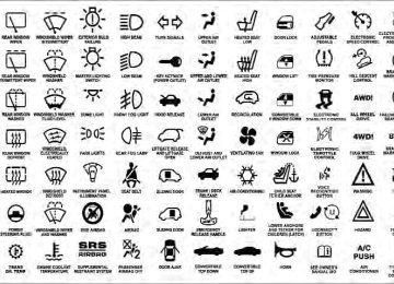
Tire Markings
492 STARTING AND OPERATING TSC is only active in the default “ESC On” mode. TSC can be disabled by pressing the “ESC Off” switch and entering “ESC Partial Off” mode. It is not active in the “ESC Partial Off” or “ESC Off” modes. Refer to the ESC portion of this section for an explanation of the different ESC operating modes.
WARNING!
If TSC activates while driving, slow the vehicle down, stop at the nearest safe location, and adjust the trailer load to eliminate trailer sway.
1 — U.S. DOT Safety Standards Code (TIN) 2 — Size Designation 3 — Service Description
4 — Maximum Load
5 — Maximum Pressure 6 — Treadwear, Traction and Temperature Grades
NOTE: • P (Passenger) - Metric tire sizing is based on U.S. design standards. P-Metric tires have the letter “P” molded into the sidewall preceding the size designa- tion. Example: P215/65R15 95H. • European-Metric tire sizing is based on European design standards. Tires designed to this standard have the tire size molded into the sidewall beginning with the section width. The letter ⬙P⬙ is absent from this tire size designation. Example: 215/65R15 96H. • LT (Light Truck) - Metric tire sizing is based on U.S. design standards. The size designation for LT-Metric
STARTING AND OPERATING 493
tires is the same as for P-Metric tires except for the letters “LT” that are molded into the sidewall preced- ing the size designation. Example: LT235/85R16. • Temporary spare tires are spares designed for tempo- rary emergency use only. Temporary high pressure compact spare tires have the letter “T” or “S” molded into the sidewall preceding the size designation. Ex- ample: T145/80D18 103M. • High flotation tire sizing is based on U.S. design standards and it begins with the tire diameter molded into the sidewall. Example: 31x10.5 R15 LT.494 STARTING AND OPERATING Tire Sizing Chart
Size Designation:
EXAMPLE:
P = Passenger car tire size based on U.S. design standards ⴖ....blank....ⴖ = Passenger car tire based on European design standards LT = Light truck tire based on U.S. design standards T or S= Temporary spare tire 31 = Overall diameter in inches (in) 215 = Section width in millimeters (mm) 65 = Aspect ratio in percent (%)
— Ratio of section height to section width of tire
10.5 = Section width in inches (in) R = Construction code
— ⬙R⬙ means radial construction — ⬙D⬙ means diagonal or bias construction
15 = Rim diameter in inches (in)
EXAMPLE:
STARTING AND OPERATING 495
Service Description:
95 = Load Index
— A numerical code associated with the maximum load a tire can carry
H = Speed Symbol
— A symbol indicating the range of speeds at which a tire can carry a load corresponding to its load index under certain operating conditions — The maximum speed corresponding to the speed symbol should only be achieved under specified operating conditions (i.e., tire pressure, vehicle loading, road conditions, and posted speed limits)
Load Identification:
ⴖ....blank....ⴖ = Absence of any text on the sidewall of the tire indicates a Standard Load (SL) tire Extra Load (XL) = Extra load (or reinforced) tire Light Load (LL) = Light load tire C, D, E, F, G = Load range associated with the maximum load a tire can carry at a specified pressure
Maximum Load — Maximum load indicates the maximum load this tire is designed to carry Maximum Pressure — Maximum pressure indicates the maximum permissible cold tire inflation pressure for this tire
496 STARTING AND OPERATING Tire Identification Number (TIN) The TIN may be found on one or both sides of the tire, however, the date code may only be on one side. Tires with white sidewalls will have the full TIN, including the date code, located on the white sidewall side of the tire.
Look for the TIN on the outboard side of black sidewall tires as mounted on the vehicle. If the TIN is not found on the outboard side, then you will find it on the inboard side of the tire.
EXAMPLE:
DOT MA L9 ABCD 0301
DOT = Department of Transportation
— This symbol certifies that the tire is in compliance with the U.S. Department of Transportation tire safety standards and is approved for highway use
MA = Code representing the tire manufacturing location (two digits) L9 = Code representing the tire size (two digits) ABCD = Code used by the tire manufacturer (one to four digits) 03 = Number representing the week in which the tire was manufactured (two digits)
—03 means the 3rd week.
01 = Number representing the year in which the tire was manufactured (two digits)
—01 means the year 2001
— Prior to July 2000, tire manufacturers were only required to have one number to represent the year in which the tire was manufactured. Example: 031 could represent the 3rd week of 1981 or 1991Tire Terminology And Definitions
B-Pillar
Term
Cold Tire Inflation Pressure
Maximum Inflation Pressure
Recommended Cold Tire Inflation Pressure Tire Placard
STARTING AND OPERATING 497
Definition
The vehicle B-Pillar is the structural member of the body located behind the front door. Cold tire inflation pressure is defined as the tire pressure after the vehicle has not been driven for at least 3 hours, or driven less than 1 mile (1.6 km) after sitting for a three hour period. Inflation pressure is measured in units of PSI (pounds per square inch) or kPa (kilopascals). The maximum inflation pressure is the maximum permissible cold tire inflation pressure for this tire. The maximum inflation pres- sure is molded into the sidewall. Vehicle manufacturer’s recommended cold tire inflation pressure as shown on the tire placard. A paper label permanently attached to the vehicle describing the vehicle’s loading capacity, the original equipment tire sizes and the recommended cold tire inflation pressures.
498 STARTING AND OPERATING Tire Loading And Tire Pressure
Tire And Loading Information Placard Location NOTE: The proper cold tire inflation pressure is listed on the driver’s side B-Pillar or the rear edge of the driver’s side door.
Tire And Loading Information Placard
Tire and Loading Information Placard
Tire Placard Location
This placard tells you important information about the: 1) number of people that can be carried in the vehicle 2) total weight your vehicle can carry 3) tire size designed for your vehicle 4) cold tire inflation pressures for the front, rear, and spare tires. Loading The vehicle maximum load on the tire must not exceed the load carrying capacity of the tire on your vehicle. You will not exceed the tire’s load carrying capacity if you adhere to the loading conditions, tire size, and cold tire inflation pressures specified on the Tire and Loading Information placard and in the “Vehicle Loading” section of this manual. NOTE: Under a maximum loaded vehicle condition, gross axle weight ratings (GAWRs) for the front and rear
STARTING AND OPERATING 499
axles must not be exceeded. For further information on GAWRs, vehicle loading, and trailer towing, refer to “Vehicle Loading” in this section. To determine the maximum loading conditions of your vehicle, locate the statement “The combined weight of occupants and cargo should never exceed XXX lbs or XXX kg” on the Tire and Loading Information placard. The combined weight of occupants, cargo/luggage and trailer tongue weight (if applicable) should never exceed the weight referenced here. Steps For Determining Correct Load Limit 1. Locate the statement “The combined weight of occu- pants and cargo should never exceed XXX lbs or XXX kg” on your vehicle’s placard. 2. Determine the combined weight of the driver and passengers that will be riding in your vehicle.500 STARTING AND OPERATING 3. Subtract the combined weight of the driver and pas- sengers from XXX lbs or XXX kg. 4. The resulting figure equals the available amount of cargo and luggage load capacity. For example, if “XXX” amount equals 1,400 lbs (635 kg) and there will be five 150 lb (68 kg) passengers in your vehicle, the amount of available cargo and luggage load capacity is 650 lbs (295 kg) (since 5 x 150 = 750, and 1400 – 750 = 650 lbs [295 kg]). 5. Determine the combined weight of luggage and cargo being loaded on the vehicle. That weight may not safely exceed the available cargo and luggage load capacity calculated in Step 4. 6. If your vehicle will be towing a trailer, load from your trailer will be transferred to your vehicle. Consult this manual to determine how this reduces the available cargo and luggage load capacity of your vehicle.
NOTE: • The following table shows examples on how to calcu- late total load, cargo/luggage, and towing capacities of your vehicle with varying seating configurations and number and size of occupants. This table is for illustration purposes only and may not be accurate for the seating and load carry capacity of your vehicle. • For the following example, the combined weight of occupants and cargo should never exceed 865 lbs (392 kg).
STARTING AND OPERATING 501
502 STARTING AND OPERATING
WARNING!
Safety
Overloading of your tires is dangerous. Overloading can cause tire failure, affect vehicle handling, and increase your stopping distance. Use tires of the recommended load capacity for your vehicle. Never overload them.
TIRES — GENERAL INFORMATION
Tire Pressure Proper tire inflation pressure is essential to the safe and satisfactory operation of your vehicle. Three primary areas are affected by improper tire pressure:
WARNING!
cause collisions.
sult in over-heating and tire failure.
• Improperly inflated tires are dangerous and can • Under-inflation increases tire flexing and can re- • Over-inflation reduces a tire’s ability to cushion shock. Objects on the road and chuckholes can cause damage that result in tire failure. • Over-inflated or under-inflated tires can affect vehicle handling and can fail suddenly, resulting in loss of vehicle control. • Unequal tire pressures can cause steering prob-
lems. You could lose control of your vehicle.
(Continued)
WARNING! (Continued)
• Unequal tire pressures from one side of the ve- hicle to the other can cause the vehicle to drift to the right or left. • Always drive with each tire inflated to the recom-
mended cold tire inflation pressure.
Economy Improper inflation pressures can cause uneven wear patterns to develop across the tire tread. These abnormal wear patterns will reduce tread life resulting in a need for earlier tire replacement. Under-inflation also increases tire fuel rolling consumption. Ride Comfort And Vehicle Stability Proper tire inflation contributes to a comfortable ride. Over-inflation produces a jarring and uncomfortable ride.
resistance
resulting
higher
in
STARTING AND OPERATING 503
Tire Inflation Pressures The proper cold tire inflation pressure is listed on the driver’s side “B” Pillar or rear edge of the driver’s side door. Some vehicles may have Supplemental Tire Pressure Information for vehicle loads that are less than the maximum loaded vehicle condition. Refer to “Supple- mental Tire Pressure Information” in “Starting and Op- erating” for further information. The pressure should be checked and adjusted as well as inspecting for signs of tire wear or visible damage at least once a month. Use a good quality pocket-type gauge to check tire pressure. Do not make a visual judgement when determining proper inflation. Radial tires may look properly inflated even when they are under-inflated.
504 STARTING AND OPERATING
CAUTION!
After inspecting or adjusting the tire pressure, al- ways reinstall the valve stem cap. This will prevent moisture and dirt from entering the valve stem, which could damage the valve stem.
Inflation pressures specified on the placard are always “cold tire inflation pressure.” Cold tire inflation pressure is defined as the tire pressure after the vehicle has not been driven for at least three hours or driven less than 1 mile (1.6 km) after a three hour period. The cold tire inflation pressure must not exceed the maximum infla- tion pressure molded into the tire sidewall. Check tire pressures more often if subject to a wide range of outdoor temperatures as tire pressures vary with temperature changes.
Tire pressures change by approximately 1 psi (7 kPa) per 12°F (7°C) of air temperature change. Keep this in mind when checking tire pressure inside a garage, especially in the Winter. Example: If garage temperature = 68°F (20°C) and the outside temperature = 32°F (0°C) then the cold tire inflation pressure should be increased by 3 psi (21 kPa), which equals 1 psi (7 kPa) for every 12°F (7°C) for this outside temperature condition. Tire pressure may increase from 2 to 6 psi (13 to 40 kPa) during operation. Do not reduce this normal pressure build up or your tire pressure will be too low.
Tire Pressures For High Speed Operation The manufacturer advocates driving at safe speeds within posted speed limits. Where speed limits or condi- tions are such that the vehicle can be driven at high speeds, maintaining correct tire inflation pressure is very important. Increased tire pressure and reduced vehicle loading may be required for high-speed vehicle opera- tion. Refer to original equipment or an authorized tire dealer for recommended safe operating speeds, loading and cold tire inflation pressures.
WARNING!
High speed driving with your vehicle under maxi- mum load is dangerous. The added strain on your tires could cause them to fail. You could have a serious collision. Do not drive a vehicle loaded to the maximum capacity at continuous speeds above 75 mph (120 km/h).
STARTING AND OPERATING 505
Radial Ply Tires
WARNING!
Combining radial ply tires with other types of tires on your vehicle will cause your vehicle to handle poorly. The instability could cause a collision. Al- ways use radial ply tires in sets of four (or six, in the case of trucks with dual rear wheels). Never combine them with other types of tires.
Cuts and punctures in radial tires are repairable only in the tread area because of sidewall flexing. Consult your authorized tire dealer for radial tire repairs.
506 STARTING AND OPERATING Spare Tire Matching Original Equipped Tire And Wheel – If Equipped Your vehicle may be equivalent with a spare tire and wheel in look and function as the original equipment tire and wheel found on the front or rear axle of your vehicle. This spare tire may be used in the tire rotation for your vehicle. If your vehicle has this option refer to an authorized tire dealer for the recommended tire rotation pattern. If your vehicle is not equipped with an original equip- ment tire and wheel as a spare, a non-matching tempo- rary emergency use spare may be equipped with your vehicle. Temporary use spares are engineered to be used only with your vehicle. Your vehicle may be equipped with one of the following types of non-matching tempo- rary use spares; compact, full size, or limited-use. Do not install more than one non-matching temporary use spare tire/wheel on the vehicle at any given time.
CAUTION!
Because of the reduced ground clearance, do not take your vehicle through an automatic car wash with a compact, full size or limited-use temporary spare installed. Damage to the vehicle may result.
Compact Spare Tire – If Equipped The compact spare is for temporary emergency use only. You can identify if your vehicle is equipped with a compact spare by looking at the spare tire description on the Tire and Loading Information Placard located on the driver’s side door opening or on the sidewall of the tire. Compact spare tire descriptions begin with the letter “T” or “S” preceding the size designation. Example: T145/ 80D18 103M. T, S = Temporary Spare Tire
Since this tire has limited tread life the original equip- ment tire should be repaired (or replaced) and reinstalled on your vehicle at the first opportunity. Do not install a wheel cover or attempt to mount a conventional tire on the compact spare wheel, since the wheel is designed specifically for the compact spare tire. Do not install more than one compact spare tire and wheel on the vehicle at any given time
WARNING!
Compact spares are for temporary emergency use only. With these spares, do not drive more than 50 mph (80 km/h). Temporary use spares have limited tread life. When the tread is worn to the tread wear indicators, the temporary use spare tire needs to be replaced. Be sure to follow the warnings, which apply to your spare. Failure to do so could result in spare tire failure and loss of vehicle control.
STARTING AND OPERATING 507
Full Size Spare – If Equipped The full size spare is for temporary emergency use only. This tire may look like the original equipped tire on the front or rear axle of your vehicle, but it is not. This spare tire may have limited tread life. When the tread is worn to the tread wear indicators, the temporary use full size spare tire needs to be replaced. Since it is not the same as your original equipment tire, replace (or repair) the original equipment tire and reinstall on the vehicle at the first opportunity. Limited-Use Spare – If Equipped The limited-use spare tire is for temporary emergency use only. This tire is identified by a label located on the limited-use spare wheel. This label contains the driving limitations for this spare. This tire may look like the original equipped tire on the front or rear axle of your vehicle, but it is not. Installation of this limited-use spare tire affects vehicle handling. Since it is not the same as
508 STARTING AND OPERATING your original equipment tire, replace (or repair) the original equipment tire and reinstall on the vehicle at the first opportunity.
WARNING!
Limited-use spares are for emergency use only. In- stallation of this limited-use spare tire affects vehicle handling. With this tire, do not drive more than the speed listed on the limit-use spare wheel. Keep inflated to the cold tire inflation pressure listed on your Tire and Loading Information Placard located on the driver’s side door opening. Replace (or repair) the original equipment tire at the first opportunity and reinstall it on your vehicle. Failure to do so could result in loss of vehicle control.
Tire Spinning When stuck in mud, sand, snow, or ice conditions, do not spin your vehicle’s wheels faster than 30 mph (48 km/h) or for longer than 30 seconds continuously without stopping when you are stuck. Refer to “Freeing A Stuck Vehicle” in “What To Do In Emergencies” for further information.
WARNING!
Fast spinning tires can be dangerous. Forces gener- ated by excessive wheel speeds may cause tire dam- age or failure. A tire could explode and injure some- one. Do not spin your vehicle’s wheels faster than 30 mph (48 km/h) or for more than 30 seconds continuously when you are stuck, and do not let anyone near a spinning wheel, no matter what the speed.
Tread Wear Indicators Tread wear indicators are in the original equipment tires to help you in determining when your tires should be replaced.
1 — Worn Tire 2 — New Tire
STARTING AND OPERATING 509
These indicators are molded into the bottom of the tread grooves. They will appear as bands when the tread depth becomes 1/16 in (2 mm). When the tread is worn to the tread wear indicators, the tire should be replaced. Life Of Tire The service life of a tire is dependent upon varying factors including, but not limited to: • Driving style • Tire pressure • Distance drivenWARNING!
Tires and the spare tire should be replaced after six years, regardless of the remaining tread. Failure to follow this warning can result in sudden tire failure. You could lose control and have a collision resulting in serious injury or death.
510 STARTING AND OPERATING Keep dismounted tires in a cool, dry place with as little exposure to light as possible. Protect tires from contact with oil, grease, and gasoline. Replacement Tires The tires on your new vehicle provide a balance of many characteristics. They should be inspected regularly for wear and correct cold tire inflation pressure. The manu- facturer strongly recommends that you use tires equiva- lent to the originals in size, quality and performance when replacement is needed. (Refer to the paragraph on “Tread Wear Indicators”). Refer to the “Tire and Loading Information” placard for the size designation of your tire. The Load Index and Speed Symbol for your tire will be found on the original equipment tire sidewall. See the Tire Sizing Chart example found in the Tire Safety Information section of this manual for more information relating to the Load Index and Speed Symbol of a tire.
It is recommended to replace the two front tires or two rear tires as a pair. Replacing just one tire can seriously affect your vehicle’s handling. If you ever replace a wheel, make sure that the wheel’s specifications match those of the original wheels. It is recommended you contact your original equipment or an authorized tire dealer with any questions you may have on tire specifications or capability. Failure to use equivalent replacement tires may adversely affect the safety, handling, and ride of your vehicle.
WARNING!
• Do not use a tire, wheel size or rating other than that specified for your vehicle. Some combinations of unapproved tires and wheels may change sus- pension dimensions and performance characteris- tics, resulting in changes to steering, handling, and braking of your vehicle. This can cause unpredict- able handling and stress to steering and suspen- sion components. You could lose control and have a collision resulting in serious injury or death. Use only the tire and wheel sizes with load ratings approved for your vehicle. • Never use a tire with a smaller load index or capacity other than what was originally equipped on your vehicle. Using a tire with a smaller load index could result in tire overloading and failure. You could lose control and have a collision.
(Continued)
STARTING AND OPERATING 511
WARNING! (Continued)
• Failure to equip your vehicle with tires having adequate speed capability can result in sudden tire failure and loss of vehicle control.
CAUTION!
Replacing original tires with tires of a different size may result in false speedometer and odometer read- ings.
SUPPLEMENTAL TIRE PRESSURE INFORMATION — IF EQUIPPED A light load vehicle condition is defined as two passen- gers [150 lbs (68 kg) each] plus 200 lbs (91 kg) of cargo. Cold tire inflation pressures for a lightly loaded vehicle will be found on the face of the driver’s door.
512 STARTING AND OPERATING TIRE CHAINS Use “Class S” chains, or other traction aids that meet SAE Type “S” specifications. Use “Class U” chains on 2500/3500 model trucks, or other traction aids that meet SAE Type “U” specifica- tions. NOTE: Chains must be the proper size for the vehicle as recommended by the chain manufacturer.
CAUTION!
To avoid damage to your vehicle, tires or chains, observe the following precautions:
(Continued)
CAUTION! (Continued)
• Because of limited chain clearance between tires and other suspension components, it is important that only chains in good condition are used. Bro- ken chains can cause serious vehicle damage. Stop the vehicle immediately if noise occurs that could suggest chain breakage. Remove the damaged parts of the chain before further use. • Install chains as tightly as possible and then • Do not exceed 45 mph (72 km/h). • Drive cautiously and avoid severe turns and large • Do not install tire chains on front wheels of 4x2
• Do not drive for a prolonged period on dry pave-retighten after driving about 0.5 mile (0.8 km).
bumps, especially with a loaded vehicle.
vehicles.
ment.
(Continued)
STARTING AND OPERATING 513
• On 4x4 2500 model trucks, the use of class “U” snow chains is permitted on the rear wheels only of trucks equipped with LT245/70R17, LT265/70R17, or LT285/ 70R17 tires. • On 4x2 and 4x4 3500 SRW (Single Rear Wheel) model trucks, the use of class “U” snow chains is permitted on the rear wheels only of trucks equipped with LT265/70R17 tires. • On 4x2 and 4x4 3500 DRW (Dual Rear Wheel) model trucks, the use of class “U” snow chains is permitted on the front and rear wheels of trucks equipped with LT235/80R17 tires.
CAUTION! (Continued)
• Observe the tire chain manufacturer’s instructions on method of installation, operating speed, and conditions for usage. Always use the lower sug- gested operating speed of the chain manufacturer if different than the speed recommended by the manufacturer.
These cautions apply to all chain traction devices, includ- ing link and cable (radial) chains. NOTE: • On 4x2 and 4x4 1500 model trucks, the use of class “S” snow chains is permitted on the rear wheels only of trucks equipped with P265/70R17 tires. • On 4x2 2500 model trucks, the use of class “U” snow chains is permitted on the rear wheels only of trucks equipped with LT245/70R17 or LT265/70R17 tires.
514 STARTING AND OPERATING
CAUTION!
Do not use tire chains on the front wheels of any model except for 3500 DRW (Dual Rear Wheel) trucks equipped with LT235/80R17 tires. There may not be adequate clearance for the chains and you are risking structural or body damage to your vehicle. Do not use tire chains on the rear wheels of 1500 model trucks equipped with LT275/70R17, P275/60R20, or 285/45R22 tires. There may not be adequate clearance for the chains and you are risking structural or body damage to your vehicle.
SNOW TIRES Some areas of the country require the use of snow tires during the winter. All season tires can be identified by the M+S designation on the tire sidewall.
If you need snow tires, select tires equivalent in size and type to the original equipment tires. Use snow tires only in sets of four; failure to do so may adversely affect the safety and handling of your vehicle. Snow tires generally have lower speed ratings than what was originally equipped with your vehicle and should not be operated at sustained speeds over 75 mph (120 km/h). For speeds above 75 mph (120 km/h) refer to original equipment or an authorized tire dealer for recommended safe operating speeds, loading and cold tire inflation pressures. While studded tires improve performance on ice, skid and traction capability on wet or dry surfaces may be poorer than that of non-studded tires. Some states pro- hibit studded tires; local laws should be checked before using these tire types.
therefore,
TIRE ROTATION RECOMMENDATIONS Tires on the front and rear axles of vehicles operate at different loads and perform different steering, driving, and braking functions. For these reasons, they wear at unequal rates. These effects can be reduced by timely rotation of tires. The benefits of rotation are especially worthwhile with aggressive tread designs such as those on all season type tires. Rotation will increase tread life, help to maintain mud, snow and wet traction levels and contribute to a smooth, quiet ride. Refer to the “Maintenance Schedule” for the proper maintenance intervals. More frequent rotation is permis- sible if desired. The reasons for any rapid or unusual wear should be corrected prior to rotation being per- formed.
STARTING AND OPERATING 515
The suggested rotation method is the “forward cross” shown in the following diagram. This rotation pattern does not apply to some directional tires that must not be reversed.Tire Rotation
516 STARTING AND OPERATING Directional Tires – If Equipped For the R/T package with 22” tires & wheels, tire rotation must be performed with consideration of the tire rotation direction. The recommended rotation pattern for direc- tional tires is shown below.
Dual Rear Wheels – If Equipped
Tire Rotation
Tire Rotation
The tires used on dual wheel assemblies should be matched for wear to prevent overloading one tire in a set. To check if tires are even, lay a straight edge across all four tires. The straight edge should touch all the tires.
CAUTION!
3500 Dual Rear Tires have only one approved direc- tion of rotation. This is to accommodate the asym- metrical design (tread pattern) of the On/Off-Road tire and the use of Outline White Letter (OWL) tires. • When replacing a flat, the spare tire may have to be remounted on the rim, or installed at a different location, to maintain the correct placement of the tire on the wheel relative to the tire/wheel position on the truck. For example, if the spare is used to replace an outer rear tire it will have to be re- mounted on the rim so that the wheel is dished inward. That way the tread design of asymmetrical tires and the white writing of the OWL tires will maintain proper position.
STARTING AND OPERATING 517
TIRE PRESSURE MONITOR SYSTEM (TPMS) The Tire Pressure Monitor System (TPMS) will warn the driver of a low tire pressure based on the vehicle recom- mended cold placard pressure. The tire pressure will vary with temperature by about 1 psi (6.9 kPa) for every 12°F (6.5°C). This means that when the outside temperature decreases, the tire pressure will decrease. Tire pressure should always be set based on cold inflation tire pressure. This is defined as the tire pressure after the vehicle has not been driven for at least three hours, or driven less than 1 mile (1.6 km) after a three hour period. The cold tire inflation pressure must not exceed the maximum inflation pressure molded into the tire sidewall. Refer to “Tires – General Information” in “Starting and Operating” for information on how to properly inflate the vehicle’s tires. The tire pressure will also increase as the vehicle is driven - this is normal and there should be no adjustment for this increased pres- sure.
518 STARTING AND OPERATING The TPMS will warn the driver of a low tire pressure if the tire pressure falls below the low-pressure warning limit for any reason, including low temperature effects and natural pressure loss through the tire. The TPMS will continue to warn the driver of low tire pressure as long as the condition exists, and will not turn off until the tire pressure is at or above the recommended cold placard pressure. Once the low tire pressure warn- ing (Tire Pressure Monitoring [TPM] Telltale Light) illu- minates, you must increase the tire pressure to the recommended cold placard pressure in order for the TPM Telltale Light to turn off. The system will automatically update and the TPM Telltale Light will turn off once the system receives the updated tire pressures. The vehicle may need to be driven for up to 20 minutes above 15 mph (24 km/h) in order for the TPMS to receive this informa- tion.
For example, your vehicle may have a recommended cold (parked for more than three hours) placard pressure of 30 psi (207 kPa). If the ambient temperature is 68°F (20°C) and the measured tire pressure is 27 psi (186 kPa), a temperature drop to 20°F (-7°C) will decrease the tire pressure to approximately 23 psi (158 kPa). This tire pressure is sufficiently low enough to turn ON the TPM Telltale Light. Driving the vehicle may cause the tire pressure to rise to approximately 27 psi (186 kPa), but the TPM Telltale Light will still be ON. In this situation, the TPM Telltale Light will turn OFF only after the tires are inflated to the vehicle’s recommended cold placard pres- sure value.
CAUTION!
• The TPMS has been optimized for the original equipment tires and wheels. TPMS pressures and warning have been established for the tire size equipped on your vehicle. Undesirable system operation or sensor damage may result when us- ing replacement equipment that is not of the same size, type, and/or style. Aftermarket wheels can cause sensor damage. Do not use aftermarket tire sealants or balance beads if your vehicle is equipped with a TPMS, as damage to the sensors may result. • After inspecting or adjusting the tire pressure, always reinstall the valve stem cap. This will prevent moisture and dirt from entering the valve stem, which could damage the TPM sensor.
STARTING AND OPERATING 519
while adjusting your tire pressure.
NOTE: • The TPMS is not intended to replace normal tire care and maintenance or to provide warning of a tire failure or condition. • The TPMS should not be used as a tire pressure gauge • Driving on a significantly under-inflated tire causes the tire to overheat and can lead to tire failure. Under-inflation also reduces fuel efficiency and tire tread life, and may affect the vehicle’s handling and stopping ability. • The TPMS is not a substitute for proper tire mainte- nance, and it is the driver’s responsibility to maintain correct tire pressure using an accurate tire pressure gauge, even if under-inflation has not reached the level to trigger illumination of the TPM Telltale Light.
520 STARTING AND OPERATING
• Seasonal temperature changes will affect tire pressure, and the TPMS will monitor the actual tire pressure in the tire.
Base System The Tire Pressure Monitor System (TPMS) uses wireless technology with wheel rim mounted electronic sensors to monitor tire pressure levels. Sensors mounted to each wheel as part of the valve stem transmit tire pressure readings to the receiver module. It is particularly important for you to check the NOTE: tire pressure in all of the tires on your vehicle monthly and to maintain the proper pressure. The TPMS consists of the following components: • Receiver module, • Four TPM sensors, and • TPM Telltale Light
The matching full size spare wheel and tire assembly (if equipped) has a TPM sensor. The matching full size spare can be used in place of any of the four road tires. The TPMS will only monitor the pressure in the full size spare when it is used in place of a road tire. Otherwise, a spare with a pressure below the low-pressure limit will not cause the TPM Telltale Light to illuminate or the chime to sound. Tire Pressure Monitoring Low Pressure Warnings
The TPM Telltale Light will illuminate in the instrument cluster, a “LOW TIRE PRESSURE” message will display in the EVIC, and a chime will sound when tire pressure is low in one or more of the four active road tires. Should this occur, you should stop as soon as possible, check the inflation pressure of each tire on your vehicle, and inflate each tire to the vehicle’s recommended cold placard pressure value. Once the system receives the updated tire pressures, the system will automatically update and the TPM Telltale Light will
turn off. The vehicle may need to be driven for up to 20 minutes above 15 mph (24 km/h) in order for the TPMS to receive this information. Service TPMS Warning If a system fault is detected, the TPM Telltale Light will flash on and off for 75 seconds and then remain on solid. The system fault will also sound a chime. If the ignition switch is cycled, this sequence will repeat, providing the system fault still exists. The TPM Telltale Light will turn off when the fault condition no longer exists. A system fault can occur due to any of the following: 1. Signal interference due to electronic devices or driving next to facilities emitting the same radio frequencies as the TPM sensors. 2. Installing aftermarket window tinting that contains materials that may block radio wave signals. 3. Accumulation of snow or ice around the wheels or wheel housings.
STARTING AND OPERATING 521
4. Using tire chains on the vehicle. 5. Using wheels/tires not equipped with TPM sensors. Vehicles With Full Size Spare 1. The matching full size spare wheel and tire assembly has a TPM sensor that can be monitored by the TPMS. 2. If you install the full size spare in place of a road tire that has a pressure below the low-pressure warning limit, upon the next ignition switch cycle, a chime will sound, a “LOW TIRE PRESSURE” message will be displayed, and the TPM Telltale Light will turn ON. 3. Driving the vehicle for up to 20 minutes above 15 mph (24 km/h) will turn off the TPM Telltale Light and “LOW TIRE PRESSURE” text message, as long as no tire pres- sure is below the low-pressure warning limit in any of the four active road tires.
522 STARTING AND OPERATING Premium System – If Equipped The Tire Pressure Monitor System (TPMS) uses wireless technology with wheel rim mounted electronic sensors to monitor tire pressure levels. Sensors mounted to each wheel as part of the valve stem transmit tire pressure readings to the receiver module. It is particularly important for you to check the NOTE: tire pressure in all of the tires on your vehicle monthly and to maintain the proper pressure. The TPMS consists of the following components: • Receiver module, • Four TPM sensors, • Various TPMS messages, which display in the Elec- • TPM Telltale Light
tronic Vehicle Information Center (EVIC), and
The matching full size spare wheel and tire assembly (if equipped) has a TPM sensor. The full size spare can be used in place of any of the four road tires. A spare with a pressure below the low-pressure limit will not cause the TPM Telltale Light to illuminate or the chime to sound. Tire Pressure Monitoring Low Pressure Warnings
The TPM Telltale Light will illuminate in the instrument cluster and a chime will sound when tire pressure is low in one or more of the four active road tires. In addition, the EVIC will display a “LOW TIRE PRESSURE” message for a minimum of five seconds and a graphic showing the pressure values of each tire with the low tire pressure values flashing.
STARTING AND OPERATING 523
Should this occur, you should stop as soon as possible and inflate the tires with a low pressure condition (those flashing in the EVIC graphic) to the vehicle’s recom- mended cold placard pressure inflation value. Once the system receives the updated tire pressures, the system will automatically update, the graphic display in the EVIC will stop flashing, and the TPM Telltale Light will turn off. The vehicle may need to be driven for up to 20 minutes above 15 mph (24 km/h) in order for the TPMS to receive this information.524 STARTING AND OPERATING Service TPMS Warning If a system fault is detected, the TPM Telltale Light will flash on and off for 75 seconds and then remain on solid. The system fault will also sound a chime. In addition, the EVIC will display a “SERVICE TPM SYSTEM” message for five seconds and then display dashes (- -) in place of the pressure value to indicate which sensor is not being received.
If the ignition switch is cycled, this sequence will repeat, providing the system fault still exists. If the system fault no longer exists, the TPM Telltale Light will no longer flash, and the “SERVICE TPM SYSTEM” message will no longer display, and a pressure value will display in place of the dashes. A system fault can occur due to any of the following: 1. Signal interference due to electronic devices or driving next to facilities emitting the same radio frequencies as the TPM sensors. 2. Installing aftermarket window tinting that contains materials that may block radio wave signals. 3. Accumulation of snow or ice around the wheels or wheel housings. 4. Using tire chains on the vehicle. 5. Using wheels/tires not equipped with TPM sensors.
The EVIC will also display a “SERVICE TPM SYSTEM” message for a minimum of five seconds when a system fault possibly related to an incorrect sensor location fault is present. In this case, the “SERVICE TPM SYSTEM” message is then followed by a graphic display with pressure values still shown. This indicates that the pres- sure values are still being received from the TPM sensors but they may not be in the correct vehicle position. The system still needs to be serviced as long as the “SERVICE TPM SYSTEM” message exists.
STARTING AND OPERATING 525
Vehicles With Full Size Spare 1. The matching full size spare wheel and tire assembly has a TPM sensor that can be monitored by the TPMS. 2. If you install the full size spare in place of a road tire that has a pressure below the low-pressure warning limit, upon the next ignition switch cycle, a chime will sound and the TPM Telltale Light will turn ON. In addition, the EVIC will display a low pressure message and a graphic showing the low tire pressure value flashing. 3. After driving the vehicle for up to 20 minutes above 15 mph (24 km/h) the TPM Telltale Light will turn OFF, as long as no tire pressure is below the low-pressure warning limit in any of the four active road tires.
526 STARTING AND OPERATING Tire Pressure Monitor System (TPMS) Tire Light Load Inflation Switch Description (2500 Models) – If Equipped
WARNING!
Never operate your vehicle with the TPMS and tire pressures set to the Light Load Inflation Pressure settings if carrying more than two occupants (150 lbs [68 kg] each) plus 200 lbs (91 kg) of cargo. The vehicle “Light Load Definition” is found in the Supplemen- tal Tire Pressure Information Label which is located on the rear face of the driver door opening. Failure to do so may cause you to lose control resulting in a collision, causing serious or fatal injury.
The TPMS tire light load inflation switch will allow the driver to switch between the max load inflation pressure (cold) low pressure warning threshold and the light load inflation pressure (cold) low pressure warning threshold depending on the vehicle’s load condition. The Tire and Loading Information label defines the recommended front and rear cold tire inflation pressures for the vehicle when operating in the Max Load condition. A Supple- mental Tire Pressure Information label is also available defining Light Load tire inflation pressures when oper- ating in the Light Load condition. When the tire light load inflation switch LED is ON, the TPMS is using the light load inflation pressure (cold) low inflation warning thresholds.
STARTING AND OPERATING 527
Tire Light Load Inflation Switch Operation – If Equipped • This vehicle may have different recommended tire pressure values between the front and rear tires as shown in both the Tire Loading Information Label and the Supplemental Tire Pressure Information Label. It is also equipped to be driven with tire pressures appro- priate to either a Light Load condition or the vehicle Max Load condition.
Tire Light Load Inflation Switch
528 STARTING AND OPERATING
• The tire light load inflation switch will allow the driver to change between the max load inflation pressure (cold) low pressure warning threshold and the light load inflation pressure (cold) low pressure warning threshold depending on the vehicle’s load condition. Refer to the “Supplemental Tire Pressure Information” label for the vehicle’s Light Load inflation pressures and “Tire and Loading Information” label for the vehicle’s Max Load inflation pressures.
Example Supplemental Tire Pressure Label
To switch from the max load inflation pressure (cold) low pressure warning threshold to the light load inflation pressure (cold) low pressure warning threshold, begin by placing the ignition switch in the RUN position. Next, lower all four road tire pressures to the Light Load Inflation Pressure values as listed on the Supplemental
Tire Pressure Information label. The Supplemental Tire Pressure Information label is located on the rear face of the driver door opening. Use an accurate tire gauge to check the tire pressures when lowering all four tire pressures. The vehicle may need to be driven above 15 mph (24 km/h) to receive this updated pressure information. After all four tire pressures have been lowered to the Light Load inflation pressures, press the tire light load inflation switch. If the tire light load inflation switch’s amber colored LED turns ON, the TPMS is using the light load inflation pressure (cold) low pressure warning thresholds. If the tire light load inflation switch amber colored LED flashes on and off for 10 seconds, after all four tire pressures have been lowered to the Light Load inflation pressures, the pressure in any one of the four tires may not be at the light load inflation pressure (cold) values as indicated for the Light Load condition as defined on the
STARTING AND OPERATING 529
Supplemental Tire Pressure Information label located on the rear face of the driver door. Using an accurate tire pressure gauge, re-check the tire pressures for the light load inflation pressure (cold) value.WARNING!
It is the driver’s responsibility to change to the max load inflation pressure (cold) low pressure warning threshold condition when not driving in the light load condition as defined as two occupants (150 lbs [68 kg] each) plus 200 lbs (91 kg) of cargo. The vehicle “Light Load Definition” is found in the Supplemen- tal Tire Pressure Information label located on the rear face of the driver door. Failure to do so may cause you to lose control resulting in a collision, causing seri- ous or fatal injury.
530 STARTING AND OPERATING To switch back to the max load inflation pressure (cold) low pressure warning threshold, press the tire light load inflation switch. It is not necessary to first fill the tires to the max load inflation pressure (cold) values to switch the TPMS system to the max load inflation pressure (cold) low pressure warning threshold. If after pressing the tire light load inflation switch, and tire pressures are below the max load inflation pressure (cold) low pressure warning thresholds, the TPMS low pressure warning telltale light (located in the instrument cluster) will turn ON and a chime will sound. The tire pressures are now required to be inflated to the max load inflation pressure (cold) values described on the Tire and Loading Informa- tion label. The Tire and Loading Information label is located on the drivers side B-pillar. If the tire light load inflation switch LED turns OFF, the TPMS has been reset and the TPMS is using the max load inflation pressure (cold) low pressure warning thresholds.
General Information This device complies with Part 15 of the FCC rules and RSS 210 of Industry Canada. Operation is subject to the following conditions: • This device may not cause harmful interference. • This device must accept any interference received, including interference that may cause undesired operation.
The TPM sensors are regulated under one of the follow- ing licenses:
United States . . . . . . . . . . . . . . . . . . . MRXC4W4MA4
Canada . . . . . . . . . . . . . . . . . . . . . 2546A-C4W4MA4FUEL REQUIREMENTS
3.7L and 4.7L Engine
These engines are designed to meet all emissions regulations and provide excel- lent fuel economy and performance when using high quality unleaded “regular” gasoline having an octane rating of 87. The use of premium gasoline is not recom- mended, as it will not provide any benefit over regular gasoline in these engines. 5.7L Engine
This engine is designed to meet all emis- sions regulations and provide satisfactory fuel economy and performance when us- ing high quality unleaded gasoline having an octane range of 87 to 89. The manufac- turer recommends the use of 89 octane for
STARTING AND OPERATING 531
optimum performance. The use of premium gasoline is not recommended, as it will not provide any benefit over regular gasoline in these engines. Light spark knock at low engine speeds is not harmful to your engine. However, continued heavy spark knock at high speeds can cause damage and immediate service is required. Poor quality gasoline can cause problems such as hard starting, stalling, and hesitations. If you experi- ence these symptoms, try another brand of gasoline before considering service for the vehicle. Over 40 auto manufacturers worldwide have issued and endorsed consistent gasoline specifications (the World- wide Fuel Charter, WWFC) which define fuel properties necessary to deliver enhanced emissions, performance, and durability for your vehicle. The manufacturer recom- mends the use of gasoline that meets the WWFC speci- fications if they are available.532 STARTING AND OPERATING Reformulated Gasoline Many areas of the country require the use of cleaner burning gasoline referred to as “Reformulated Gasoline.” Reformulated gasolines contain oxygenates and are spe- cifically blended to reduce vehicle emissions and im- prove air quality. The manufacturer supports the use of reformulated gaso- lines. Properly blended reformulated gasolines will pro- vide excellent performance and durability for the engine and fuel system components. Gasoline/Oxygenate Blends Some fuel suppliers blend unleaded gasoline with oxy- genates such as Ethanol. Fuels blended with oxygenates may be used in your vehicle.
CAUTION!
DO NOT use gasoline containing Methanol or gaso- line containing more than 10% Ethanol. Use of these blends may result in starting and driveability prob- lems, damage critical fuel system components, cause emissions to exceed the applicable standard, and/or cause the “Malfunction Indicator Light” to illumi- nate. Pump labels should clearly communicate if a fuel contains greater than 10% Ethanol.
Problems that result from using gasoline containing Methanol or gasoline containing more than 10% Ethanol are not the responsibility of the manufacturer and may not be covered under warranty. E-85 Usage In Non-Flex Fuel Vehicles Non-FFV vehicles are compatible with gasoline contain- ing 10% ethanol (E10). Gasoline with higher ethanol content may void the vehicle’s warranty.
If a Non-FFV vehicle is inadvertently fueled with E-85
fuel, the engine will have some or all of these symptoms: • operate in a lean mode • OBD II “Malfunction Indicator Light” on • poor engine performance • poor cold start and cold drivability • increased risk for fuel system component corrosion To fix a Non-FFV vehicle inadvertently fueled once with E-85 perform the following: • drain the fuel tank (see your authorized dealer) • change the engine oil and oil filter • disconnect and reconnect the battery to reset theengine controller memory
More extensive repairs will be required for prolonged exposure to E-85 fuel.
STARTING AND OPERATING 533
MMT In Gasoline MMT is a manganese containing metallic additive that is blended into some gasoline to increase octane. Gasoline blended with MMT provides no performance advantage beyond gasoline of the same octane number without MMT. Gasoline blended with MMT reduces spark plug life and reduces emissions system performance in some vehicles. The manufacturer recommends that gasoline without MMT be used in your vehicle. The MMT content of gasoline may not be indicated on the gasoline pump, therefore, you should ask your gasoline retailer whether or not his/her gasoline contains MMT. It is even more important to look for gasolines without MMT in Canada, because MMT can be used at levels higher than those allowed in the United States. MMT is prohibited in Federal and California reformulated gasoline.
534 STARTING AND OPERATING Materials Added To Fuel All gasoline sold in the United States is required to contain effective detergent additives. Use of additional detergents or other additives is not needed under normal conditions and would result in unnecessary cost. There- fore, you should not have to add anything to the fuel. Fuel System Cautions
CAUTION!
Follow these guidelines to maintain your vehicle’s performance: • The use of leaded gas is prohibited by Federal law. Using leaded gasoline can impair engine perfor- mance and damage the emission control system.
(Continued)
CAUTION! (Continued)
• An out-of-tune engine or certain fuel or ignition malfunctions can cause the catalytic converter to overheat. If you notice a pungent burning odor or some light smoke, your engine may be out of tune or malfunctioning and may require immediate service. Contact your authorized dealer for service assistance. • The use of fuel additives, which are now being sold as octane enhancers are not recommended. Most of these products contain high concentra- tions of methanol. Fuel system damage or vehicle performance problems resulting from the use of such fuels or additives is not the responsibility of the manufacturer.
Intentional tampering with emissions control in civil penalties being assessed
NOTE: systems can result against you. Carbon Monoxide Warnings
WARNING!
Carbon monoxide (CO) in exhaust gases is deadly. Follow the precautions below to prevent carbon monoxide poisoning:
(Continued)
STARTING AND OPERATING 535
WARNING! (Continued)
• Do not inhale exhaust gases. They contain carbon monoxide, a colorless and odorless gas which can kill. Never run the engine in a closed area such as a garage, and never sit in a parked vehicle with the engine running for an extended period. If the vehicle is stopped in an open area with the engine running for more than a short period, adjust the ventilation system to force fresh, outside air into the vehicle. • Guard against carbon monoxide with proper maintenance. Have the exhaust system inspected every time the vehicle is raised. Have any abnor- mal conditions repaired promptly. Until repaired, drive with all side windows fully open.
536 STARTING AND OPERATING FLEXIBLE FUEL (4.7L ENGINE ONLY) — IF EQUIPPED
E-85 General Information The information in this section is for Flexible Fuel ve- hicles only. These vehicles can be identified by a unique fuel filler door label that states Ethanol (E-85) or Un- leaded Gasoline Only. This section only covers those subjects that are unique to these vehicles. Please refer to the other sections of this manual for information on features that are common between Flexible Fuel and gasoline-only powered vehicles.
E-85 Fuel Cap
CAUTION!
Only vehicles with the E-85 fuel filler door label can operate on E-85.
STARTING AND OPERATING 537
WARNING!
Ethanol vapors are extremely flammable and could cause serious personal injury. Never have any smok- ing materials lit in or near the vehicle when remov- ing the fuel filler tube cap (gas cap) or filling the tank. Do not use E-85 as a cleaning agent and never use it near an open flame.
Fuel Requirements Your vehicle will operate on both unleaded gasoline with an octane rating of 87, or E-85 fuel, or any mixture of these two. For best results, a refueling pattern that alternates between E-85 and unleaded gasoline should be avoided. When you do switch fuel types it is recommended that: • you do not switch when the fuel gauge indicates less
than 1/4 full
E-85 Badge
Ethanol Fuel (E-85) E-85 is a mixture of approximately 85% fuel ethanol and 15% unleaded gasoline.
538 STARTING AND OPERATING
• you do not add less than 5 gallons (19 Liters) when • you operate the vehicle immediately after refueling for
refueling
a period of at least 5 minutes
Observing these precautions will avoid possible hard starting and/or significant deterioration in driveability during warm up. NOTE: • When the ambient temperature is above 90° F (32° C), you may experience hard starting and rough idle following start up even if the above recommendations are followed. • Some additives used in regular gasoline are not fully compatible with E-85 and may form deposits in your engine. To eliminate driveability issues that may be caused by these deposits, a supplemental gasoline additive, such as MOPAR威 Injector Cleanup or Techron may be used.
Selection Of Engine Oil For Flexible Fuel Vehicles (E-85) And Gasoline Vehicles FFV vehicles operated on E-85 require specially formu- lated engine oils. These special requirements are included in MOPAR威 engine oils, and in equivalent oils meeting Chrysler Specification MS-6395. The manufacturer re- quires engine oils that are API Certified and meet the requirements of Material Standard MS-6395. MS-6395
contains additional requirements, developed during ex- tensive fleet testing, to provide additional protection to Chrysler Group LLC engines. Use MOPAR威 or an equivalent oil meeting the specification MS-6395. Starting The characteristics of E-85 fuel make it unsuitable for use when ambient temperatures fall below 0°F (-18°C). In the range of 0°F (-18°C) to 32°F (0°C), you may experience an increase in the time it takes for your engine to start, and a deterioration in driveability (sags and/or hesitations) until the engine is fully warmed up.NOTE: Use of the engine block heater (if equipped) is beneficial for E-85 startability when the ambient tempera- ture is less than 32°F (0°C). Cruising Range Because E-85 fuel contains less energy per gallon/liter than gasoline, you will experience an increase in fuel consumption. You can expect your miles per gallon (mpg)/miles per liter and your driving range to decrease by about 30%, compared to gasoline operation. Replacement Parts Many components in your Flexible Fuel Vehicle (FFV) are designed to be compatible with ethanol. Always be sure that your vehicle is serviced with correct ethanol com- patible parts.
STARTING AND OPERATING 539
CAUTION!
Replacing fuel system components with non-ethanol compatible components can damage your vehicle.
Maintenance
CAUTION!
Do not use ethanol mixture greater than 85% in your vehicle. It will cause difficulty in cold starting and may affect driveability.
540 STARTING AND OPERATING ADDING FUEL The fuel filler cap (gas cap) is located behind the fuel filler door, on the left side of the vehicle. Open the fuel door and remove the fuel cap by turning it counter- clockwise.
Fuel Filler Cap
NOTE: When removing the fuel filler cap, lay the cap tether in the hook, located on the fuel filler door.
CAUTION!
the fuel system.
• Damage to the fuel system or emissions control system could result from using an improper fuel tank filler tube cap (gas cap). • A poorly fitting gas cap could let impurities into • A poorly fitting gas cap may cause the “Malfunc- • To avoid fuel spillage and overfilling, do not “top off” the fuel tank after filling. When the fuel nozzle “clicks” or shuts off, the fuel tank is full.
tion Indicator Light (MIL)” to turn on.
WARNING!
• Never have any smoking materials lit in or near the vehicle when the gas cap is removed or the tank is being filled. • Never add fuel to the vehicle when the engine is • A fire may result if gasoline is pumped into a portable container that is inside of a vehicle. You could be burned. Always place gas containers on the ground while filling.
running.
NOTE: • Tighten the gas cap until you hear a “clicking” sound. This is an indication that the gas cap is tightened properly. The MIL in the instrument cluster may turn on if the gas cap is not secured properly. Make sure that the gas cap is tightened each time the vehicle is refueled.
• When the fuel nozzle “clicks” or shuts off, the fuel
STARTING AND OPERATING 541
tank is full.
Loose Fuel Filler Cap Message
If the vehicle diagnostic system determines that the fuel filler cap is loose, improperly installed, or damaged, a loose gascap indicator will display in the EVIC telltale display area. Refer to “Electronic Vehicle Information Center (EVIC) in “Understanding Your Instrument Panel” for further in- formation. Tighten the fuel filler cap properly and press the SELECT button to turn off the message. If the problem continues, the message will appear the next time the vehicle is started.
VEHICLE LOADING
Certification Label As required by National Highway Traffic Safety Admin- istration regulations, your vehicle has a certification label affixed to the driver’s side door or pillar.
542 STARTING AND OPERATING This label contains the month and year of manufacture, Gross Vehicle Weight Rating (GVWR), Gross Axle Weight Rating (GAWR) front and rear, and Vehicle Identification Number (VIN). A Month-Day-Hour (MDH) number is included on this label and indicates the Month, Day and Hour of manufacture. The bar code that appears on the bottom of the label is your VIN. Gross Vehicle Weight Rating (GVWR) The GVWR is the total permissible weight of your vehicle including driver, passengers, vehicle, options and cargo. The label also specifies maximum capacities of front and rear axle systems (GAWR). Total load must be limited so GVWR and front and rear GAWR are not exceeded. Payload The payload of a vehicle is defined as the allowable load weight a truck can carry, including the weight of the driver, all passengers, options and cargo.
Gross Axle Weight Rating (GAWR) The GAWR is the maximum permissible load on the front and rear axles. The load must be distributed in the cargo area so that the GAWR of each axle is not exceeded. Each axle GAWR is determined by the components in the system with the lowest load carrying capacity (axle, springs, tires or wheels). Heavier axles or suspension components sometimes specified by purchasers for in- creased durability does not necessarily increase the vehi- cle’s GVWR. Tire Size The tire size on the label represents the actual tire size on your vehicle. Replacement tires must be equal to the load capacity of this tire size. Rim Size This is the rim size that is appropriate for the tire size listed.
Inflation Pressure This is the cold tire inflation pressure for your vehicle for all loading conditions up to full GAWR. Curb Weight The curb weight of a vehicle is defined as the total weight of the vehicle with all fluids, including vehicle fuel, at full capacity conditions, and with no occupants or cargo loaded into the vehicle. The front and rear curb weight values are determined by weighing your vehicle on a commercial scale before any occupants or cargo are added. Loading The actual total weight and the weight of the front and rear of your vehicle at the ground can best be determined by weighing it when it is loaded and ready for operation.
STARTING AND OPERATING 543
The entire vehicle should first be weighed on a commer- cial scale to insure that the GVWR has not been exceeded. The weight on the front and rear of the vehicle should then be determined separately to be sure that the load is properly distributed over the front and rear axle. Weigh- ing the vehicle may show that the GAWR of either the front or rear axles has been exceeded but the total load is within the specified GVWR. If so, weight must be shifted from front to rear or rear to front as appropriate until the specified weight limitations are met. Store the heavier items down low and be sure that the weight is distributed equally. Stow all loose items securely before driving. Improper weight distributions can have an adverse effect on the way your vehicle steers and handles and the way the brakes operate.544 STARTING AND OPERATING
CAUTION!
Do not load your vehicle any heavier than the GVWR or the maximum front and rear GAWR. If you do, parts on your vehicle can break, or it can change the way your vehicle handles. This could cause you to lose control. Also overloading can shorten the life of your vehicle.
TRAILER TOWING In this section you will find safety tips and information on limits to the type of towing you can reasonably do with your vehicle. Before towing a trailer, carefully review this information to tow your load as efficiently and safely as possible. To maintain warranty coverage, follow the requirements and recommendations in this manual concerning ve- hicles used for trailer towing.
Common Towing Definitions The following trailer towing related definitions will assist you in understanding the following information: Gross Vehicle Weight Rating (GVWR) The GVWR is the total allowable weight of your vehicle. This includes driver, passengers, cargo and tongue weight. The total load must be limited so that you do not exceed the GVWR. Refer to “Vehicle Loading/Vehicle Certification Label” in “Starting and Operating” for further information. Gross Trailer Weight (GTW) The GTW is the weight of the trailer plus the weight of all cargo, consumables and equipment (permanent or tem- porary) loaded in or on the trailer in its ⬙loaded and ready for operation⬙ condition. The recommended way to measure GTW is to put your fully loaded trailer on a vehicle scale. The entire weight of the trailer must be supported by the scale.
Gross Combination Weight Rating (GCWR) The GCWR is the total permissible weight of your vehicle and trailer when weighed in combination. NOTE: The GCWR rating includes a 150 lbs (68 kg) allowance for the presence of a driver. Gross Axle Weight Rating (GAWR) The GAWR is the maximum capacity of the front and rear axles. Distribute the load over the front and rear axles evenly. Make sure that you do not exceed either front or rear GAWR. Refer to “Vehicle Loading/Vehicle Certifica- tion Label” in “Starting and Operating” for further information.
WARNING!
It is important that you do not exceed the maximum front or rear GAWR. A dangerous driving condition can result if either rating is exceeded. You could lose control of the vehicle and have a collision.
STARTING AND OPERATING 545
Tongue Weight (TW) The tongue weight is the downward force exerted on the hitch ball by the trailer. In most cases it should not be less than 10% or more than 15% of the trailer load. You must consider this as part of the load on your vehicle. Frontal Area The frontal area is the maximum height multiplied by the maximum width of the front of a trailer. Trailer Sway Control The trailer sway control can be a mechanical telescoping link that can be installed between the hitch receiver and the trailer tongue that typically provides adjustable fric- tion associated with the telescoping motion to dampen any unwanted trailer swaying motions while traveling. If equipped, the electronic Trailer Sway Control (TSC) recognizes a swaying trailer and automatically applies individual wheel brakes and/or reduces engine power to attempt to eliminate the trailer sway.
546 STARTING AND OPERATING Weight-Carrying Hitch A weight-carrying hitch supports the trailer tongue weight, just as if it were luggage located at a hitch ball or some other connecting point of the truck. These kind of hitches are the most popular on the market today and they are commonly used to tow small- and medium- sized trailers. Weight-Distributing Hitch A weight-distributing system works by applying lever- age through spring (load) bars. They are typically used for heavier loads to distribute trailer tongue weight to the tow vehicle’s front axle and the trailer axle(s). When used in accordance with the manufacturer’s directions, it pro- vides for a more level ride, offering more consistent steering and brake control, thereby enhancing towing safety. The addition of a friction/hydraulic sway control also dampens sway caused by traffic and crosswinds and contributes positively to tow vehicle and trailer stability. Trailer sway control and a weight distributing (load
equalizing) hitch are recommended for heavier Tongue Weights (TW) and may be required depending on vehicle and trailer configuration/loading to comply with GAWR requirements.
WARNING!
• An improperly adjusted weight distributing hitch system may reduce handling, stability and braking performance and could result in a collision. • Weight distributing systems may not be compat- ible with surge brake couplers. Consult with your hitch and trailer manufacturer or a reputable Rec- reational additional information.
Vehicle
dealer
for
STARTING AND OPERATING 547
EXAMPLE — Without Weight-Distributing
EXAMPLE — With Weight-Distributing Hitch (Correct)
Hitch (Incorrect)
548 STARTING AND OPERATING
EXAMPLE — Improper Adjustment of Weight-Distributing Hitch (Incorrect)
Fifth-Wheel Hitch The fifth-wheel hitch is a special high platform with a coupling that mounts over the rear axle of the tow vehicle in the truck bed. It connects a vehicle and fifth-wheel trailer with a coupling king pin. Gooseneck Hitch The gooseneck hitch employs a pivoted coupling arm which attaches to a ball mounted in the bed of a pickup truck. The coupling arm connects to the hitch mounted over the rear axle in the truck bed. Trailer Hitch Classification The following chart provides the industry standard for the maximum trailer weight a given trailer hitch class can tow and should be used to assist you in selecting the correct trailer hitch for your intended towing condition.
STARTING AND OPERATING 549
All trailer hitches should be professionally installed on your vehicle. Trailer Towing Weights (Maximum Trailer Weight Ratings) The rear bumper is intended to tow trailers up to 5,000 lbs (2 268 kg) without added equipment or altera- tions to the standard equipment.Trailer Hitch Classification Definitions
Class
Max. Trailer Hitch Industry
Standards
2,000 lbs (907 kg) 3,500 lbs (1587 kg)
5,000 lbs (2268 kg) 10,000 lbs (4540 kg)
Class I - Light Duty Class II - Medium Duty Class III - Heavy Duty Class IV - Extra Heavy Duty Fifth Wheel/ Gooseneck Refer to the “Trailer Towing Weights (Maximum Trailer Weight Ratings)” for the Maximum Gross Trailer Weight (GTW) towable for your given drive- train.
Greater than 10,000 lbs
(4540 kg)
550 STARTING AND OPERATING Ram 1500 4x2
3.7L V-6 4–Speed Automatic Transmission
4.7L V-8 6–Speed Automatic Transmission
5.7L HEMI威V-8 6–Speed Automatic Transmission
ST Towing: 3,750 lbs (1701 kg) - max Payload: 1,860 lbs (839 kg) - max Towing: 5,000 lbs (2268 kg) - std 7,600 lbs (3447 kg) - max Payload: 1,700 lbs (771 kg) - max Towing: 5,000 lbs (2268 kg) - std 10,400 lbs (4717 kg) - max Payload: 1,660 lbs (753 kg) - max
SLT/Outdoorsman/Sport
Laramie
—
Towing: 5,000 lbs (2268 kg) - std 7,650 lbs (3470 kg) - max Payload: 1,730 lbs (785 kg) - max Towing: 5,000 lbs (2268 kg) - std 10,450 lbs (4740 kg) - max Payload: 1,670 lbs (757 kg) - max
—
—
Towing: 5,000 lbs (2268 kg) - std 10,050 lbs (4559 kg) - max Payload: 1,610 lbs (730 kg) - max
Ram 1500 4x4
4.7L V-8 6–Speed Automatic Transmission
5.7L HEMI威V-8 6–Speed Automatic Transmission
ST Towing: 5,000 lbs (2268 kg) - std 7,400 lbs (3356 kg) - max Payload: 1,540 lbs (698 kg) - max Towing: 5,000 lbs (2268 kg) - std 10,250 lbs (4649 kg) - max Payload: 1,510 lbs (685 kg) - max
SLT/Outdoorsman/Sport Towing: 5,000 lbs (2268 kg) - std 7,450 lbs (3379 kg) - max Payload: 1,560 lbs (708 kg) - max Towing: 5,000 lbs (2268 kg) - std 10,250 lbs (4649 kg) - max Payload: 1,530 lbs (694 kg) - max
STARTING AND OPERATING 551
Laramie
—
Towing: 5,000 lbs (2268 kg) - std 9,850 lbs (4468 kg) - max Payload: 1,610 lbs (730 kg) - max
552 STARTING AND OPERATING Ram 2500 & 3500
2500 Power Wagon威
Towing: 10,100 lbs (4581 kg) - max Payload: 1,780 lbs (807 kg) - max
—
—
5.7L HEMI威 V-8 6-Speed Automatic Transmission
6.7L Cummins威 Turbo Diesel I-6 6-Speed Manual Transmission
6.7L Cummins威 Turbo Diesel I-6 6-Speed Automatic Transmission
2500 ST SLT Bighorn/ Lonestar Laramie Out- doorsman Towing: 12,300 lbs (5579 kg) - max Payload: 3,120 lbs (1415 kg) - max Towing: 13,350 lbs (6055 kg) - max Payload: 2,490 lbs (1129 kg) - max Towing: 15,450 lbs (7008 kg) - max Payload: 2,580 lbs (1170 kg) - max
3500 ST SLT Bighorn/ Lonestar Laramie Out- doorsman
—
Towing: 14,050 lbs (6372 kg) - max Payload: 5,050 lbs (2291 kg) - max Towing: 22,700 lbs (10296 kg) - max Payload: 5,130 lbs (2327 kg) - max
NOTE: For additional trailer towing information (maxi- mum trailer weight ratings) refer to the following website addresses: • http://www.ramtrucks.com. • http://www.ramtruck.ca (Canada). Trailer And Tongue Weight Always load a trailer with 60% to 65% of the weight in the front of the trailer. This places 10% to 15% of the GTW on the tow hitch of your vehicle. Loads balanced over the wheels or heavier in the rear can cause the trailer to sway severely side to side which will cause loss of control of the vehicle and trailer. Failure to load trailers heavier in front is the cause of many trailer collisions.
STARTING AND OPERATING 553
Consider the following items when computing the weight on the rear axle of the vehicle: • The tongue weight of the trailer • The weight of any other type of cargo or equipment • The weight of the driver and all passengers.
put in or on your vehicle
554 STARTING AND OPERATING NOTE: Remember that everything put into or on the trailer adds to the load on your vehicle. Also, additional factory-installed options or dealer-installed options must be considered as part of the total load on your vehicle. Refer to “Tire Safety Information/Tire and Loading In- formation Placard” in “Starting and Operating” for fur- ther information. Towing Requirements To promote proper break-in of your new vehicle drive- train components the following guidelines are recom- mended:
CAUTION!
• Do not tow a trailer at all during the first 500 miles (805 km) the new vehicle is driven. The engine, axle or other parts could be damaged.
(Continued)
CAUTION! (Continued)
• Then, during the first 500 miles (805 km) that a trailer is towed, do not drive over 50 mph (80 km/h) and do not make starts at full throttle. This helps the engine and other parts of the vehicle wear in at the heavier loads.
WARNING!
Improper towing can lead to a collision. Follow these guidelines to make your trailer towing as safe as possible:
(Continued)
STARTING AND OPERATING 555
WARNING! (Continued)
• Make certain that the load is secured in the trailer and will not shift during travel. When trailering cargo that is not fully secured, dynamic load shifts can occur that may be difficult for the driver to control. You could lose control of your vehicle and have a collision. • When hauling cargo or towing a trailer, do not overload your vehicle or trailer. Overloading can cause a loss of control, poor performance or dam- age to brakes, axle, engine, transmission, steering, suspension, chassis structure or tires. • Safety chains must always be used between your vehicle and trailer. Always connect the chains to the hook retainers of the vehicle hitch. Cross the chains under the trailer tongue and allow enough slack for turning corners.
(Continued)
WARNING! (Continued)
• Vehicles with trailers should not be parked on a grade. When parking, apply the parking brake on the tow vehicle. Put the tow vehicle transmission in PARK. For four-wheel drive vehicles, make sure the transfer case is not in NEUTRAL. Always, block or ⴖchockⴖ the trailer wheels.
• GCWR must not be exceeded. • Total weight must be distributed between the tow vehicle and the trailer such that the following four ratings are not exceeded: 1. GVWR 2. GTW 3. GAWR 4. Trailer tongue weight rating for the trailer hitch utilized (This requirement may limit the ability to always achieve the 10% to 15% range of tongue weight as a percentage of total trailer weight).
size spare tire.
556 STARTING AND OPERATING Towing Requirements – Tires • Do not attempt to tow a trailer with less than the full • Proper tire inflation pressures are essential to the safe and satisfactory operation of your vehicle. Refer to “Tires – General Information” in “Starting and Oper- ating” for proper tire inflation procedures. • Check the trailer tires for proper tire inflation pres- • Check for signs of tire wear or visible tire damage before towing a trailer. Refer to “Tires – General Information” in “Starting and Operating” for the proper inspection procedure.
sures before trailer usage.
• When replacing tires, refer to “Tires – General Infor- mation” in “Starting and Operating” for proper tire replacement procedures. Replacing tires with a higher load carrying capacity will not increase the vehicle’s GVWR and GAWR limits.
Towing Requirements – Trailer Brakes • Do not interconnect the hydraulic brake system or vacuum system of your vehicle with that of the trailer. This could cause inadequate braking and possible personal injury. • An electronically actuated trailer brake controller is required when towing a trailer with electronically actuated brakes. When towing a trailer equipped with a hydraulic surge actuated brake system, an electronic brake controller is not required.
• Trailer brakes are recommended for trailers over 1,000 lbs (454 kg) and required for trailers in excess of 2,000 lbs (907 kg).
CAUTION!
If the trailer weighs more than 1,000 lbs (454 kg) loaded, it should have its own brakes and they should be of adequate capacity. Failure to do this could lead to accelerated brake lining wear, higher brake pedal effort, and longer stopping distances.
STARTING AND OPERATING 557
WARNING!
• Do not connect trailer brakes to your vehicle’s hydraulic brake lines. It can overload your brake system and cause it to fail. You might not have brakes when you need them and could have a collision. • Towing any trailer will increase your stopping distance. When towing you should allow for addi- tional space between your vehicle and the vehicle in front of you. Failure to do so could result in a collision.
Integrated Trailer Brake Module – If Equipped Your vehicle may have an Integrated Trailer Brake Mod- ule (ITBM) for Electric and Electric Over Hydraulic (EOH) trailer brakes.
558 STARTING AND OPERATING NOTE: This module has been designed and verified with electric trailer brakes and new electric over hydrau- lic systems. Some previous EOH systems may not be compatible with ITBM.
1 — GAIN/Brake Output Power Display 2 — Manual Brake Control Lever 3 — Trailer Brake Status Indicator Light 4 — GAIN Adjustment Buttons
The user interface consists of the following: GAIN/ Brake Output Power Display Shows the current GAIN setting. This display may also be used to display diagnostic information, if needed. • SC — Short Circuit to Ground • Sb — Short to Battery • CF — Controller Fault – If this message appears on the
display, see your authorized dealer.
When the vehicle brakes are applied, the display will no longer show GAIN and will change to the output to the trailer brakes. Manual Brake Control Lever Slide the manual brake control lever to the right to activate power to the trailer’s electric brakes independent of the tow vehicle’s brakes. If the manual brake control
lever is activated while the brake is also applied, the greater of the two inputs determines the power sent to the trailer brakes. The trailer and the vehicle’s brake lamps will come on when either vehicle braking or manual trailer brakes are applied. Trailer Brake Status Indicator Light This light indicates the trailer electrical connection status. If no electrical connection is detected after the ignition is turned on, pressing the GAIN adjustment button or sliding the manual brake control lever will display the GAIN setting for 10 seconds and the “Trailer Brake Status Indicator Light” will not be displayed. If a fault is detected in the trailer wiring or the Integrated Trailer Brake Module (ITBM), the “Trailer Brake Status Indicator Light” will flash.
STARTING AND OPERATING 559
GAIN Adjustment Buttons (+/-) Pressing these buttons will adjust the brake control power output to the trailer brakes in 0.5 increments. The GAIN setting can be increased to a maximum of 10 or decreased to a minimum of 0 (no trailer braking). GAIN The GAIN setting is used to set the trailer brake control for the specific towing condition and should be changed as towing conditions change. Changes to towing condi- tions include trailer load, vehicle load, road conditions and weather. Adjusting GAIN NOTE: This should only be performed in a traffic free environment at speeds of approximately 20–25 mph (30–40 km/h).
560 STARTING AND OPERATING 1. Make sure the trailer brakes are in good working condition, functioning normally, and properly adjusted. See your trailer dealer if necessary. 2. Hook up the trailer and make the electrical connec- tions according to the trailer manufacturer’s instructions. 3. When a trailer with electric/EOH brakes is plugged in, the trailer connected message should appear in the EVIC (if the connection is not recognized by the ITBM, braking functions will not be available), the GAIN setting will illuminate and the correct type of trailer must be selected from the EVIC options. 4. Press the UP or DOWN button on the steering wheel until System Setup appears on the screen.
5. Press the SELECT button and then press the UP or DOWN buttons until Trailer Brake Type appears on the screen.
STARTING AND OPERATING 561
6. Press the SELECT button and then press the UP or DOWN buttons until the proper Trailer Brake Type appears on the screen.
1500 Models Only – Light Electric and Heavy NOTE: Electric will only be available due to the tow capacities of the vehicle. 7. Use the GAIN adjustment (+/-) buttons to increase or decrease the GAIN setting to the desired starting point. A GAIN setting of 5 is a good starting point.
562 STARTING AND OPERATING 8. In a traffic-free environment, tow the trailer on a dry, level surface at a speed of 20–25 mph (30–40 km/h) and squeeze the manual brake control lever completely. 9. If the trailer wheels lockup (indicated by squealing tires), reduce the GAIN setting; if the trailer wheels turn freely, increase the GAIN setting. Repeat Steps 8 and 9 until the GAIN setting is at a point just below trailer wheel lockup. If towing a heavier trailer, trailer wheel lockup may not be attainable even with the maximum GAIN setting of 10. EVIC Display Messages The trailer brake control interacts with the Electronic Vehicle Information Center (EVIC). Display messages, along with a single chime, will be displayed when a malfunction is determined in the trailer connection, trailer brake control, or on the trailer. Refer to “Electronic Vehicle Information Center” in “Understanding Your Instrument Panel” for further information.
CAUTION!
Connecting a trailer that is not compatible with the ITBM system may result in reduced or complete loss of trailer braking. There may be a increase in stop- ping distance or trailer instability which could result in damage to your vehicle, trailer, or other property.
WARNING!
Connecting a trailer that is not compatible with the ITBM system may result in reduced or complete loss of trailer braking. There may be a increase in stop- ping distance or trailer instability which could result in personal injury.
NOTE: • An aftermarket controller may be available for use with air trailer brake systems and other systems not
compatible with ITBM. To determine the type of brakes on your trailer and the availability of control- lers, check with your trailer manufacturer or dealer. • Removal of the ITBM will cause errors and it may cause damage to the electrical system and electronic modules of the vehicle. See your authorized dealer if an aftermarket module is to be installed.
Towing Requirements – Trailer Lights And Wiring Whenever you pull a trailer, regardless of the trailer size, stop lights and turn signals on the trailer are required for motoring safety. The Trailer Tow Package will include a four and seven- pin wiring harness. Use a factory approved trailer har- ness and connector. NOTE: Do not cut or splice wiring into the vehicle’s wiring harness.
STARTING AND OPERATING 563
The electrical connections are all complete to the vehicle but you must mate the harness to a trailer connector. Refer to the following illustrations.1 — Female Pins 2 — Male Pin 3 — Ground