- 2005 Nissan Murano Owners Manuals
- Nissan Murano Owners Manuals
- 2007 Nissan Murano Owners Manuals
- Nissan Murano Owners Manuals
- 2012 Nissan Murano Owners Manuals
- Nissan Murano Owners Manuals
- 2009 Nissan Murano Owners Manuals
- Nissan Murano Owners Manuals
- 2004 Nissan Murano Owners Manuals
- Nissan Murano Owners Manuals
- 2011 Nissan Murano Owners Manuals
- Nissan Murano Owners Manuals
- 2003 Nissan Murano Owners Manuals
- Nissan Murano Owners Manuals
- 2010 Nissan Murano Owners Manuals
- Nissan Murano Owners Manuals
- 2006 Nissan Murano Owners Manuals
- Nissan Murano Owners Manuals
- Download PDF Manual
-
쐌 Make sure the selector lever is in the P position and the ignition switch is turned to the LOCK position.
the chime sounds continuously when the
If driver’s door is opened, check the following:
Alarm and warning when the engine starts When the key warning light 쎻A is blinking in red and the outside buzzer sounds, make sure the Intelligent Key is inside the vehicle. Warning for low battery power 쐌 This warning is to let you know that
the battery of the Intelligent Key will run down soon. Replace it with a new one. Refer to the “8. Maintenance and do-it-yourself” section for battery replacement. • The green blinking key warning light 쎻A the Pre-driving checks and adjustments 3-17
goes out about 30 seconds after
墌 06.7.5/Z50-D/V5.0 墍
ignition switch is turned to ON.
쐌 We recommend replacing the battery at a
NISSAN dealer.
Preventing the Intelligent Key from being left in the vehicle If you lock all doors using the power door lock switch with the Intelligent Key in the vehicle, all of the doors unlock immediately and the buzzer will warn you when the door is closed.
3-18 Pre-driving checks and adjustments
墌 06.7.5/Z50-D/V5.0 墍
TROUBLE-SHOOTING GUIDE Symptom
Possible Cause
When pushing the door handle request switch or the lift gate request switch
The outside buzzer sounds for approxi- mately 2 seconds.
The doors cannot be locked.
When closing the doors
When locking the doors
When opening the driver’s door
When stopping the engine When turning the ignition switch When starting the engine
The outside buzzer sounds for approxi- mately 10 seconds. The key warning light in the instrument panel blinks in red and the outside buzzer sounds 3 times. The outside buzzer sounds for approxi- mately 3 seconds and all doors unlock. The outside buzzer sounds for approxi- mately 3 seconds and all doors unlock.
A warning chime sounds continuously.
The P position warning light in the in- strument panel blinks in red. A warning chime sounds continuously. The key warning light in the instrument panel blinks in green.
The ignition switch is not turned to the LOCK position.
The Intelligent Key has been left in the ve- hicle. The Intelligent Key has been left in the trunk room. The ignition switch is not in the LOCK posi- tion, or the mechanical key or valet key is inserted into the ignition switch.
The selector lever is not in the P position. The ignition switch is not turned to the LOCK position. The battery charge is low.
When pushing the ignition switch
The key warning light in the instrument panel comes on in red.
The Intelligent Key is not in the vehicle.
Remedy
Take out the Intelligent Key from the vehicle and push the door handle request switch or the lift gate request switch. Turn the ignition switch to the LOCK posi- tion and push the door handle request switch or the lift gate request switch while carrying the Intelligent Key with you. Close all the doors securely and push the door handle request switch or the lift gate request switch while carrying the Intelligent Key with you. Turn the ignition switch to the LOCK posi- tion.
Take out the Intelligent Key from the vehicle and close the door. Take out the Intelligent Key from the vehicle and close the door. Turn the ignition switch to the LOCK posi- tion. Remove the mechanical key or valet key from the ignition switch. Make sure that the selector lever is in the P position. Turn the ignition switch to the LOCK posi- tion. Replace the battery with a new one. See “BATTERY REPLACEMENT” on page 8-24. If the key warning light comes on in red even while you are carrying the Intelligent Key, the battery is completely discharged. Replace the battery with a new one. See “BATTERY REPLACEMENT” on page 8-24.
The Intelligent Key is not in the vehicle.
Be sure to carry the Intelligent Key with you.
Pre-driving checks and adjustments 3-19
墌 06.7.5/Z50-D/V5.0 墍
쐌 the Intelligent Key is too far away from the
vehicle
쐌 the Intelligent Key battery runs down After locking with the Intelligent remote keyless entry function, pull the door handle to make sure the doors are securely locked. The operating range varies depending on the environment. To securely operate the LOCK and UNLOCK buttons on the Intelligent Key, ap- proach the vehicle to about 3 ft (1 m) from the door. The panic alarm will not activate when the mechanical key or the valet key is in the ignition switch.
Trouble-shooting examples When it is difficult to turn the ignition switch 쐌 Push the ignition switch and turn it to the left
and then to the right.
쐌 While gently turning the steering wheel to the
left or right, turn the ignition switch.
OPERATION WITH INTELLIGENT REMOTE KEYLESS ENTRY SYSTEM It is possible to lock/unlock all doors, fuel-filler door, activate the panic alarm and open the windows by pushing the buttons on the Intelli- gent Key from outside the vehicle. Before locking the doors, make sure the key is not left in the vehicle. The LOCK/UNLOCK button on the Intelligent Key can operate at a distance of approximately 33 ft (10 m) from the vehicle. (The effective distance depends upon the conditions around the vehicle.) As many as 4 Intelligent Key can be used with one vehicle. For information concerning the pur- chase and use of an additional Intelligent Key, contact a NISSAN dealer. The LOCK and UNLOCK buttons on the Intelli- gent Key will not operate when: 3-20 Pre-driving checks and adjustments
SPA1926
쎻A LOCK button 쎻B UNLOCK button 쎻C PANIC alarm How to use remote keyless entry system Setting hazard indicator and horn (buzzer) mode:
This vehicle is set in hazard indicator and horn (buzzer) mode when you first receive the vehicle. The hazard indicator and horn (buzzer) mode also can be changed with vehicle electronic systems on the monitor. See “4.
墌 06.7.5/Z50-D/V5.0 墍
Display screen, heater, air conditioner and audio systems”.
For buzzer operation, refer to the following chart.
In hazard indicator and horn (buzzer) mode, when the LOCK button 쎻A is pushed, the hazard indicator flashes twice and the horn chirps once (refer to the “operation guide” chart for the Intelligent Key request switch mode). When the UNLOCK button 쎻B is pushed, the hazard indi- cator flashes once.
If hazard indicator and horn mode is not neces- sary, you can switch to hazard indicator only mode by following the switching procedure.
In hazard indicator only mode, when the LOCK button 쎻A is pushed, the hazard indicator flashes twice. When the UNLOCK button 쎻B is pushed, neither the hazard indicator nor the horn oper- ates.
(Switching procedure) Push the LOCK 쎻A and UNLOCK 쎻B buttons on the Intelligent key simultaneously for more than 2
seconds to switch from one mode to the other.When pushing the buttons to set hazard indica- tor mode, the hazard indicator flashes 3 times. When pushing the buttons to set hazard indica- tor and horn mode, the hazard indicator flashes
SPA1950A
once and the horn chirps once. Locking doors and fuel-filler door:
1. Remove the mechanical key or the valet key if
any key is in the ignition switch.*1
2. Close all the doors.*2
3. Push the LOCK button 쎻A on the IntelligentKey.
4. All the doors (including lift gate) and fuel-filler
door will lock.
All of the doors will lock when the LOCK button 쎻A on the Intelligent Key is pushed
Pre-driving checks and adjustments 3-21
墌 06.7.5/Z50-D/V5.0 墍
even though the ignition switch is in the ON position.
5. The hazard indicator flashes twice and the
horn chirps once.
쐌 When the LOCK button 쎻A is pushed with all doors locked, the hazard indicator flashes twice and the horn chirps once as a reminder that the doors are already locked.
*1: Doors lock with the Intelligent Key while the mechanical key or the valet key is in the ignition switch or the ignition switch is pushed in.
*2: Doors do not lock and buzzer sounds when the LOCK button is pushed while any door is open.
Unlocking doors and fuel-filler door: 1. Push the UNLOCK button 쎻B on the Intelli-
gent Key once.
쐌 The driver’s door and fuel-filler door unlock 쐌 The hazard indicator flashes once if all doors are completely closed with the ignition switch in any position except the ON position.
쐌 The interior light turns on and the light timer activates for 30 seconds when the switch is in the DOOR position with the ignition switch in any position except the ON position.
3-22 Pre-driving checks and adjustments
2. Push the UNLOCK button 쎻B on the Intelli-
gent Key again within 5 seconds.
쐌 All doors unlock. 쐌 Lift gate unlocks. 쐌 The hazard indicator flashes once if all doors
are completely closed.
All doors will be locked automatically unless one of the following operations is performed within 1
minute of pushing the UNLOCK button 쎻B . 쐌 any door is open 쐌 the ignition switch is pushed 쐌 the mechanical key or the valet key is insertedinto the ignition switch
The interior light can be turned off without waiting for 30 seconds by turning the ignition switch to the ON position or by locking the doors with the Intelligent Key. Opening and closing front windows: 쐌 To open the windows, push the UNLOCK button 쎻B for about 3 seconds or turn the driver’s door key lock with the metal key to the rear of the vehicle for about 2 seconds after the door is unlocked. To stop opening, release the UNLOCK but- ton 쎻B or turn the key to the neutral position.
쐌 To close the front windows, turn the driver’s door key lock to the front of the vehicle for about 2 seconds after the door is locked. To stop closing, turn the key to the neutral position.
The door windows will open or close while turning the metal key. See “Doors” earlier in this section. Using the panic alarm: If you are near your vehicle and feel threatened, you may activate the alarm to call attention as follows: 1. Push the PANIC button 쎻C on the Intelligent Key for longer than 0.5 seconds with the metal key removed from the ignition switch or the ignition switch not pushed in.
2. The theft warning alarm and headlights will
stay on for 25 seconds.
3. The panic alarm stops when: 쐌 It has run for 25 seconds, or 쐌 Any of the buttons on the Intelligent Key are
pushed.
墌 06.7.5/Z50-D/V5.0 墍
Windows open/close with the mechanical key See “Opening and closing windows” on the previous page.
쐌 To install the mechanical key to the intelligent key, securely lock the lock knob and then check that the mechanical key will not move.
CAUTION
Be sure to carry the Intelligent Key with the mechanical key installed in it.
Locking/unlocking the doors with the key (mechanical key and valet key) The doors can be locked/unlocked by inserting the mechanical and valet key into the key cylin- der in the driver’s door in the same way as the ordinary key. Starting the engine with the mechanical key and valet key 1. Securely depress the brake pedal. 2.
Insert the mechanical key or the valet key into the ignition switch.
3. Turn the ignition switch to the START posi-
tion and start the engine.
4. After starting the engine, release the switch. For important safety information, see the “5. Starting and driving” section.
SPA1951
OPERATION WITH THE MECHANICAL KEY AND VALET KEY If the Intelligent Key cannot be used because its battery is discharged, use the metal key to lock or unlock the doors and use the mechanical key or the valet key, which is registered to the NISSAN Vehicle Immobilizer System compo- nents, to start the engine. Removing the mechanical key 쐌 Release the lock knob at the back of the intelligent key and remove the mechanical key.
Pre-driving checks and adjustments 3-23
墌 06.7.5/Z50-D/V5.0 墍
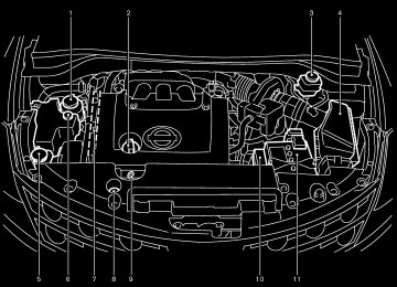
HOOD
LIFT GATE
1. Pull the hood lock release handle 쎻1 located below the instrument panel; the hood will then spring up slightly.
2. Move the lever 쎻2 at the front of the hood
with your fingertips and raise the hood.
3. When closing the hood, slowly close the
hood and make sure it locks into place.
3-24 Pre-driving checks and adjustments
SPA1578
WARNING
쐌 Make sure the hood is completely closed and latched before driving. Failure to do so could cause the hood to fly open and result in an accident. 쐌 If you see steam or smoke coming to
from the engine compartment, avoid injury do not open the hood.
SPA1947
쐌 The power door lock system allows you to lock or unlock all doors including the lift gate simultaneously.쐌 Push the opener switch and pull up the lift
gate to open.
WARNING
Do not drive with the lift gate open. This could allow dangerous exhaust gases to be drawn into the vehicle. See “Precau- tions when driving”
starting
and
墌 06.7.5/Z50-D/V5.0 墍
in the “5. Starting and driving” section for exhaust gas.
WARNING
쐌 Always be sure the lift gate has been closed securely to prevent it from opening while driving.
쐌 Do not drive with the lift gate open. This could allow dangerous exhaust gases to be drawn into the vehicle.
SPA1915
Emergency unlock lever If the lift gate cannot be opened with the door lock switch or remote controller due to a dis- charged battery, follow the next steps. 1. Remove the cover inside of the lift gate with a
suitable tool.
2. Move the lever toward the direction 쎻A as
illustrated to open the lift gate.
Contact a NISSAN dealer as soon as possible.
Pre-driving checks and adjustments 3-25
墌 06.7.5/Z50-D/V5.0 墍
FUEL-FILLER DOOR
switch once model).
(Intelligent Key
equipped
쐌 Push the passenger side door handle request switch or lift gate request switch twice (Intel- ligent Key equipped model).
To lock, close the fuel-filler door and lock the doors.
SPA1580
OPEN THE FUEL-FILLER DOOR To open the fuel-filler door, unlock it using one of the following operations, then push the right- hand side of the lid 쎻A . 쐌 Push the unlock button on the remote keyless
entry once.
쐌 Insert the key into the door lock cylinder and
turn the door key clockwise twice.
쐌 Push the power door lock switch to the
unlock side.
쐌 Push the driver’s side door handle request
3-26 Pre-driving checks and adjustments
墌 06.7.5/Z50-D/V5.0 墍
FUEL-FILLER CAP The fuel-filler cap is a ratcheting type. Turn the cap counterclockwise 쎻A to remove. To tighten, turn the cap clockwise until ratchet- ing clicks are heard. Put the fuel-filler cap on the cap holder 쎻B while refueling.
WARNING
쐌 Gasoline is extremely flammable and
SPA1581A
highly explosive under certain condi- tions. You could be burned or seri- ously injured if it is misused or mis- handled. Always stop the engine and do not smoke or allow open flames or sparks near the vehicle when refu- eling.
쐌 Fuel may be under pressure. Turn the cap a third of a turn, and wait for any “hissing sound” to stop to prevent fuel from spraying out and possibly causing personal injury. Then remove the cap.
쐌 Do not attempt to top off the fuel tank after the fuel pump nozzle shuts off automatically. Continued refueling may cause fuel overflow, resulting in fuel spray and possibly a fire.
쐌 Use only an original equipment type fuel-filler cap as a replacement. It has a built-in safety valve needed for proper operation of the fuel system and emission control system. An in- correct cap can result in a serious It malfunction and possible injury. could also cause the malfunc- tion indicator light to come on.
쐌 Do not fill a portable fuel container in the vehicle or trailer. Static electricity can cause an explosion of flammable liquid, vapor or gas in any vehicle or trailer. To reduce the risk of serious injury or death when filling portable fuel containers: — Always place the container on the
ground when filling.
— Do not use electronic devices
Pre-driving checks and adjustments 3-27
墌 06.7.5/Z50-D/V5.0 墍
when filling.
— Keep the pump nozzle in contact with the container while you are filling it.
— Use only approved portable fuel
containers for flammable liquid.
쐌 Never pour fuel into the throttle body
to attempt to start your vehicle.
CAUTION
쐌 If fuel is spilled on the vehicle body, flush it away with water to avoid paint damage.
쐌 Tighten until the fuel-filler cap clicks. Failure to tighten the fuel-filler cap mal- properly may cause the function indicator light (MIL) to illu- light illuminates minate. If the because the fuel-filler cap is loose or missing, tighten or install the cap and continue to drive the vehicle. The light should turn off after a few light does
driving trips. If the
3-28 Pre-driving checks and adjustments
STEERING WHEEL
not turn off after a few driving trips, have the vehicle inspected by a NISSAN dealer.
쐌 For additional information, see the “Malfunction indicator light (MIL)” in the “Instruments and controls” sec- tion.
SPA1582
WARNING
쐌 Do not adjust the steering wheel while driving. You could lose control of your vehicle and cause an acci- dent.
쐌 Do not put anything on or near the
steering wheel when tilting.
TILT OPERATION The steering wheel will pop up when the lock
墌 06.7.5/Z50-D/V5.0 墍
PEDAL POSITION ADJUSTMENT (if so equipped)
lever is pulled as illustrated 쎻1 . Keep holding the lock lever and adjust steering wheel to the desired position 쎻2 . Release the lock lever to lock the steering wheel.
the
CAUTION
Do not adjust the pedal position with your foot on the pedal.
SPA1574
The accelerator and brake pedals can be ad- justed for driving comfort. Use the pedal adjusting switch to adjust the brake and accelerator pedal position forward 쎻1
or backward 쎻2 . Pedal adjustment can only be performed when: 쐌 Ignition switch is in the OFF, ACC or LOCKposition, or
쐌 Ignition switch is ON and the selector lever is
in the P (Park) position
The brake and accelerator pedals cannot be adjusted separately.
Pre-driving checks and adjustments 3-29
墌 06.7.5/Z50-D/V5.0 墍
SUN VISORS
MIRRORS
CAUTION
쐌 Do not store the main sun visor be- fore storing the extension sun visor. 쐌 Do not pull the extension sun visor
forcedly downward.
1. To block out glare from the front, swing down
the main sun visor 쎻1 .
2. To block glare from the side, remove the main sun visor from the center mount and swing it to the side 쎻2 .
3. Draw out the extension sun visor 쎻3 from the
main sun visor 쎻4 to block further glare.
SPA1756
INSIDE MIRROR While holding the inside rearview mirror, adjust the mirror angles until the desired position is achieved. The adjusting lever 쎻1 can be operated when the glare from the headlights of the vehicle behind you obstructs your vision at night.
WARNING
Use the night position only when neces- sary, because it reduces rear view clar-
3-30 Pre-driving checks and adjustments
SPA2176
墌 06.7.5/Z50-D/V5.0 墍
ity.
light goes off), and the inside mirror will operate normally. To turn on the system again, push the MIRROR switch once again. For the HomeLink Universal Transceiver and the compass display, see the description in the “2. Instruments and controls” section. Do not hang any object on the mirror or apply glass cleaner. Doing so will reduce the sensitivity of the sensor, resulting in improper operation.
SPA2177
AUTOMATIC ANTI-GLARE INSIDE MIRROR (if so equipped) The inside mirror is designed so that it automati- cally changes reflection according to the inten- sity of the headlights of the vehicle following you.
The anti-glare system will be automatically turned on when you turn the ignition switch to the ON position. When the inside MIRROR switch 쎻A is turned on (The indicator light 쎻B will illuminate), exces- sive glare from the headlights of the vehicle behind you will be reduced. Push the MIRROR switch 쎻A to turn the system off (the indicator
Pre-driving checks and adjustments 3-31
墌 06.7.5/Z50-D/V5.0 墍
selector lever, will operate only when the ignition switch is in the ACC or ON position. Move the switch to right 쎻A or left 쎻B to select the right or left outside mirror, then adjust the mirror to the desired position by pushing the button 쎻C .
SPA1449A
OUTSIDE MIRRORS
WARNING
Objects viewed in the outside mirror on the passenger side are closer than they appear. Be careful when moving to the right. Using only this mirror could cause an accident. Use the inside mirror or glance over your shoulder to properly judge distances to other objects.
The outside mirror switch, located in front of the 3-32 Pre-driving checks and adjustments
SPA1829
Foldable outside mirrors Fold the outside mirror by pushing it toward the rear of the vehicle.
墌 06.7.5/Z50-D/V5.0 墍
AUTOMATIC DRIVE POSITIONER (if so equipped) The automatic drive positioner system has two features: 쐌 Entry/exit function 쐌 Memory storage ENTRY/EXIT FUNCTION This system is designed so that the driver’s seat and outside mirror will automatically move when the selector lever is in the P (Park) position. This allows the driver to get into and out of the driver’s seat more easily.
The driver’s seat will slide backward:
The driver’s seat will slide backward when the driver’s door is opened with the ignition switch (knob) in the LOCK position.
The driver’s seat will return to the previous position: 쐌 When the key is inserted into the ignition switch after closing the driver’s door, or when the driver’s door is closed after inserting the key into the ignition switch.
쐌 The driver’s seat will not return to the previ- ous positions if the seat adjusting switch is operated when the seat is at the exit position. The entry/exit feature can be canceled. See “4. Display screen, heater, air conditioner and audio systems” section of this manual. The entry/exit function can be activated or can- celled by pressing and holding the SET switch for more than 10 seconds while the ignition key is in the LOCK position. The indicator light will blink once when the function is cancelled, and light will blink twice when the the indicator function is activated. the battery cable is disconnected, or if the fuse opens, the entry/exit function will be cancelled. In such a case, after connecting the battery or replacing with a new fuse, open and close the driver’s door more than two times with the ignition key or ignition switch in the LOCK position to activate the entry/exit function.
If
쐌 When the ignition switch is pushed with the (Intelligent Key
closed.
driver’s equipped model)
door
쐌 When the key or ignition switch is turned to
the ON position.
SPA2185
MEMORY STORAGE Two positions for the driver’s seat, pedals (Brake and Accelerator) and outside mirrors can be stored in the automatic drive positioner memory. Follow these procedures to use the memory system.
1. Set the selector lever to the P (Park) position.
2. Adjust the driver’s seat, pedals (Brake and Accelerator) and outside mirrors to the de- sired positions by manually operating each adjusting switch. For additional information, see “Seats” in the “1. Safety — seats, seat belts and supplemental restraint system” Pre-driving checks and adjustments 3-33
墌 06.7.5/Z50-D/V5.0 墍
section and “Pedal position adjustment” and “Outside mirrors” earlier in this section.
3. Turn the ignition ON.
4. Push the SET switch and, within 5 seconds, push the memory switch (1 or 2) fully for at least 1 second.
The indicator light for the pushed memory switch will come on and stay on for approxi- mately 5 seconds after pushing the switch. After the indicator light goes off, the selected positions are stored in the selected memory (1 or 2).
If memory is stored in the same memory switch, the previous memory will be deleted. Linking a remote keyless entry to a stored memory position A remote keyless entry can be linked to a stored memory position with the following procedure. 1. Follow the steps for storing a memory posi-
tion.
for
light
2. While the indicator
the memory switch being set is illuminated for 5 seconds, push the unlock button on the remote keyless entry. The indicator light will blink. After the indicator light goes off, the remote keyless entry is linked to that memory setting.
3-34 Pre-driving checks and adjustments
With the key removed from the ignition switch, push the unlock button on the keyfob. The driver’s seat, pedals (Brake and Accelerator) and outside mirrors will move to the memorized position. Confirming memory storage 쐌 Turn the ignition switch to the ON position and push the SET switch. If the main memory has not been stored, the indicator light will come on for approximately 0.5 seconds. When the memory has stored the position, the indicator light will stay on for approxi- mately 5 seconds.
쐌 If the battery cable is disconnected, or if the fuse opens, the memory will be canceled. In this case, reset the desired position using the previous procedure.
쐌 If a new memory is stored,
the previous memory and link will be erased. In this case, reset the desired position and link using the previous procedure.
Selecting the memorized position 1. Set the selector lever to the P (Park) position. 2. Turn the ignition ON. 3. Push the memory switch (1 or 2) fully for at
least 1 second.
The driver’s seat, pedals (Brake and Accel- erator) and outside mirrors will move to the memorized position with the indicator light flashing, and then the light will stay on for approximately 5 seconds. SYSTEM OPERATION The automatic drive positioner system will not work or will stop operating under the following conditions: 쐌 when the vehicle speed is above 4 MPH (7
km/h).
쐌 when the adjusting switch for the driver’s seat, pedals and outside mirror are operated while the automatic drive positioner is oper- ating.
쐌 when the memory switch (1 or 2) and the least 1
SET switch is not pushed for at second.
쐌 when the seat, pedals and outside mirror have been already moved to the memorized positions.
쐌 when no seat, pedals and outside mirror positions are stored in the memory switch. 쐌 when the engine is started while moving the
automatic drive positioner.
쐌 when the selector lever is moved from the P
墌 06.7.5/Z50-D/V5.0 墍
position to any other position (However, it will not be cancelled if the switch is pushed while the seat is returning to the previous positions (entry/exit function).).
Pre-driving checks and adjustments 3-35
墌 06.7.5/Z50-D/V5.0 墍
MEMO
3-36 Pre-driving checks and adjustments
墌 06.7.5/Z50-D/V5.0 墍
4 Display screen, heater, air conditioner and
audio systems
Safety note .............................................................................. 4-2
Control panel buttons — without navigation system.... 4-2
How to use joystick and “ENTER” button................. 4-3
How to use “BACK” button .......................................... 4-3
How to use “TRIP” button............................................. 4-3
How to use “FUEL ECON” button.............................. 4-3
Clock ................................................................................... 4-4
How to use “E/M” button .............................................. 4-4
How to use “MAINT” (Maintenance) button ............. 4-4
Maintenance notice ......................................................... 4-5
How to use “SETTING” button .................................... 4-6
“DAY/NIGHT” button.................................................... 4-10
Control panel buttons — with navigation system ....... 4-11
How to use joystick and “ENTER” button .............. 4-11
How to use “BACK” button........................................ 4-11
Setting up the start-up screen................................... 4-12
How to use the “TRIP” button ................................... 4-12
Maintenance notice....................................................... 4-14
How to use the “SETTING” button .......................... 4-15
“DAY/NIGHT” button.................................................... 4-19
RearView Monitor (if so equipped)................................. 4-19
How to read the displayed lines................................ 4-20RearView Monitor setting ............................................ 4-20
Operating tips................................................................. 4-20
Ventilators.............................................................................. 4-21
Heater and air conditioner (Automatic) ......................... 4-23
Automatic operation...................................................... 4-24
Manual operation ........................................................... 4-25
Operating tips................................................................. 4-25
In-cabin microfilter......................................................... 4-26
Servicing air conditioner.................................................... 4-26
Audio system ........................................................................ 4-27
FM radio reception........................................................ 4-27
AM radio reception ....................................................... 4-28
Satellite radio reception............................................... 4-28
Audio operation precautions....................................... 4-28
FM-AM-SAT radio with CD player .......................... 4-34
FM-AM-SAT radio with cassette player and CD changer ............................................................................ 4-38
CD care and cleaning .................................................. 4-43
Steering switch for audio control (if so equipped)......................................................................... 4-43
Antenna ............................................................................ 4-44
Car phone or CB radio .................................................... 4-45墌 06.7.5/Z50-D/V5.0 墍
SAFETY NOTE
CONTROL PANEL BUTTONS — WITHOUT NAVIGATION SYSTEM
WARNING
쐌 Do not disassemble or modify this system. If you do, it may result in accidents, fire, or electrical shock.
쐌 Do not use this system if you notice any abnormality, such as a frozen screen or lack of sound. Continued use of the system may result in acci- dent, fire or electric shock.
쐌 In case you notice any foreign object in the system hardware, spill liquid on it, or notice smoke or smell com- ing from it, stop using the system immediately and contact a NISSAN dealer. Ignoring such conditions may lead to accidents, fire, or electrical shock.
1. “TRIP” button
2. “FUEL ECON” button
3. Clock adjust button
4. “TRIP RESET” button
SAA1352
5. “E/M” button
6. “DAY/NIGHT” button
7. “BACK” button
8. JOYSTICK and “ENTER” button
4-2 Display screen, heater, air conditioner and audio systems
墌 06.7.5/Z50-D/V5.0 墍
9. “SETTING” button 10. “MAINT” maintenance button Make sure the engine is running before using this system. If you use the system with the engine not running (ignition ON or ACC) for a long time, it will use up all the battery power, and the engine will not start. HOW TO USE JOYSTICK AND “ENTER” BUTTON Choose an item on the display using the joystick. Push the “ENTER” button only when the use of it is instructed on the display. HOW TO USE “BACK” BUTTON Finish setup: If you push the “BACK” button after the setup is completed, the display will return to the previous screen.
SAA1317
SAA1318
HOW TO USE “TRIP” BUTTON When the “TRIP” button is pushed, the following modes will display on the screen. TRIP 1 (TIME, DIST, AVG) → TRIP 2 (TIME, DIST, AVG) → OFF Elapsed Time, Driving Distance and Average Speed will be displayed. To reset, select the “Reset” key using the joy- stick and push the “ENTER” button, or push the “TRIP RESET” or “TRIP” button for more than approximately 1.5 seconds.
HOW TO USE “FUEL ECON” BUTTON Average Fuel Economy and Distance to Empty will be displayed for reference when the “FUEL ECON” button is pushed. To reset, select the “Reset” key using the joy- stick and push the “ENTER” button, or push the “TRIP RESET” or “TRIP” button for more than approximately 1.5 seconds.
Display screen, heater, air conditioner and audio systems 4-3
墌 06.7.5/Z50-D/V5.0 墍
To finish the adjusting, push the “BACK” button or the screen will return to normal after 10
seconds. The clock can be adjusted on the setting display. See the “HOW TO USE “SETTING” BUTTON” later in this section. HOW TO USE “E/M” BUTTON You can change the unit as follows using the “E/M” (English/Metric) button. Unit: US — Mile, °F, MPGMetric — km, °C, L/100 km
SAA1353
CLOCK The digital clock displays time when the ignition switch is in ACC or ON. If the battery cable is disconnected, the clock will not indicate the correct time. Readjust the time. Adjusting the time To adjust the time, push the “H” or “M” button for more than approximately 1.5 seconds. The time indicator will flash. Push the H button to adjust the hour. Push the M button to adjust the minute. 4-4 Display screen, heater, air conditioner and audio systems
SAA1319
HOW TO USE “MAINT” (Maintenance) BUTTON Maintenance and tire pressure information (if so equipped) will be displayed when the “MAINT” button is pushed.
To display the setting of the maintenance inter- val, select the “Engine Oil” or “Tire Rotation” key using the joystick and push the “ENTER” button.
the maintenance interval, select
To set the “Maintenance Schedule” key by using the joy- stick and move the joystick to the right or left.
To reset the maintenance interval, select the
墌 06.7.5/Z50-D/V5.0 墍
The “MAINTENANCE NOTICE” screen displays each time the key is turned ON until one of the following conditions are met: 쐌 “RESET” is selected. 쐌 “Display Maintenance Notification” is set
OFF.
쐌 the maintenance interval is set again.
SAA1320
SAA1354
“Reset” key using the joystick and push the “ENTER” button. To display the MAINTENANCE NOTICE, auto- matically when setting trip distance is reached, select the “Display Maintenance Notification” key and push the “ENTER” button.
MAINTENANCE NOTICE The “MAINTENANCE NOTICE” screen (“EN- GINE OIL” or “TIRE ROTATION”) will be auto- matically displayed as shown when both of the following conditions are met: 쐌 the vehicle is driven the set distance and the
ignition switch is turned OFF.
쐌 the ignition key is turned ON the next time the
vehicle will be driven.
To return to the previous display after the “MAINTENANCE NOTICE” screen is displayed, push the “BACK” button.
Display screen, heater, air conditioner and audio systems 4-5
墌 06.7.5/Z50-D/V5.0 墍
TIRE or CHECK ALL TIRE) is displayed on the screen: FLAT TIRE — Check All Tires.
WARNING
쐌 When a spare tire is mounted or a wheel is replaced, tire pressure will not be indicated, the Tire Pressure Monitoring System (TPMS) will not function and the low tire pressure warning light will flash for approxi- mately 1 minute and remain on after the 1 minute. Contact your NISSAN dealer as soon as possible for tire replacement and/or system reset- ting.
쐌 Replacing tires with those not origi- nally specified by NISSAN could af- fect the TPMS.
the proper operation of
SAA1321
Tire pressure information (if so equipped) Pressure indication in ** psi on the screen indicates that the pressure is being measured. After a few driving trips, the pressure for each tire will be displayed randomly. The order of tire pressure figures displayed on the screen does not correspond with the actual order of the tire position. Tire pressure rises and falls depending on the heat caused by the vehicle’s traveling condition and the temperature. In case of low tire pressure, a message (FLAT 4-6 Display screen, heater, air conditioner and audio systems
SAA1355
HOW TO USE “SETTING” BUTTON The SETTINGS screen will appear when the “SETTING” button is pushed.
墌 06.7.5/Z50-D/V5.0 墍
Display Off: To turn off the screen, push the “SETTING” button and select the “Display” key and “Display Off” key. The indicator of the “Display Off” will turn on. When any mode button is pushed with the screen off, the screen turns on for further operation. The screen will turn off automatically 5
seconds after the operation is finished. To turn on the screen, push the “SETTING” button and select the “Display” key and “Display Off” key, then set the screen to on by pushing the “ENTER” button. Setting Audio or HVAC display: Choose the “Audio” or “HVAC” (Heater and air conditioner) key to be displayed at the bottom, by using the joystick. The audio or HVAC (heater, air conditioner) setting condition will normally appear on the screen. To return to the setting screen, push the “SETTING” button or “BACK” button.SAA1550
“Display” settings The DISPLAY SETTINGS screen will appear when selecting the “Display” key and pushing the “ENTER” button. Brightness/Contrast: To adjust the brightness and contrast of the screen, select the “Brightness/Contrast” key and push the “ENTER” button. Then you can adjust the brightness to Darker or Brighter, the contrast to Lower or Higher using the joystick.
SAA1357
Vehicle electronic systems The VEHICLE ELECTRONIC SYSTEMS screen will appear when selecting the “Vehicle Elec- tronic Systems” key with the joystick and push- ing the “ENTER” button. You can set operating conditions. To set an operating condition, select the appli- cable item using the joystick, and push the “ENTER” button. The indicator light alternately turns on and off each time the “ENTER” button is pushed. Indicator light is illuminated. — ON
the various electronic systems
Display screen, heater, air conditioner and audio systems 4-7
墌 06.7.5/Z50-D/V5.0 墍
the Intelligent Key to return to the previ- ous mode.
Auto Re-Lock Time:
The length of the auto door re-lock time can be set. Select the “Auto Re-Lock Time” key, then move the joystick and push the ENTER button to adjust the time. Sensitivity of Automatic Headlights:
Automatic light illumination can be set as de- sired.
Select the “Sensitivity of Automatic Headlights” key, then move the joystick to the left (lower) or right (higher). Automatic Headlights Off Delay:
You can control how long it takes the automatic turn off timer to extinguish the headlights in the AUTO position.
Select the “Automatic Headlights Off Delay” key, then move the joystick to the left or right to adjust the timer. Speed Dependent Wiper:
When this item is turned to on, the wiper interval is adjusted automatically according to the ve- hicle speed.
SAA1548
SAA1549
Indicator light is not illuminated. — OFF Adjust driver seat when exiting vehicle: The driver’s seat automatically moves back and returns to the original position for ease of exit and entry. Selective door unlock: This key can switch the unlock doors of the 1st unlocking operation as follows: ON (Only the driver side door) ←→ OFF (All the doors)
Keyless Remote Response — Horn*:
This key changes the horn chirp mode that occurs when pushing the LOCK button on the keyfob or the Intelligent Key. Keyless Remote Response — Lights*:
This key changes the hazard indicator flash mode that occurs when pushing the LOCK or UNLOCK button on the keyfob or the Intelligent Key. * Even if you change the horn chirp or the hazard flash with the keyfob or the Intel- ligent Key, the change may not be re- flected in the display. Use the keyfob or
4-8 Display screen, heater, air conditioner and audio systems
墌 06.7.5/Z50-D/V5.0 墍
Intelligent Key Lock Response — Sound (if so equipped): The sound pattern of the Intelligent request switch operation can be set as desired. Select the “Intelligent Key lock response — Sound” key, then push the ENTER button to change the sound pattern. Intelligent Key Unlock Response — Beep Sound (if so equipped): The beep sounds when unlocking door with the Intelligent request switch can be turned on or off. Return All Settings to Default: When this key is selected and turned on using the “ENTER” button, all settings made by VEHICLE ELECTRONICS will return to the initial conditions.
SAA1327
SAA1353
System settings Language/Unit: The LANGUAGE/UNIT screen will appear when selecting the “Language/Unit” key and pushing the “ENTER” button. Language: English or French Unit: US — Mile, °F, MPG
Metric — km, °C, L/100 km
You can select the language and unit using the joystick and “ENTER” button.
Clock: Adjusting the time Select the “Hours” or “Minutes” key and move the joystick to the right or left to adjust the time. The time will change step by step. After completion of the setting, push the “BACK” button.
Display screen, heater, air conditioner and audio systems 4-9
墌 06.7.5/Z50-D/V5.0 墍
“DAY/NIGHT” BUTTON Pushing the “DAY/NIGHT” button will change the display to the DAY or NIGHT display. Then, adjust the brightness moving the joystick right or left. If no operation is done within 10 seconds, or if the “BACK” button is pushed, the display will return to the previous display. Pushing the “DAY/NIGHT” button for more than approximately 2 seconds will turn the display off and on.
4-10 Display screen, heater, air conditioner and audio systems
墌 06.7.5/Z50-D/V5.0 墍
CONTROL PANEL BUTTONS — WITH NAVIGATION SYSTEM
1. “DAY/NIGHT” button 2. “BACK” button 3. Joystick and “ENTER” button 4. “SETTING” button 5. “TRIP” button 쎻A : For Navigation system control buttons; refer to the separate Navigation System Owner’s Manual.
When you use this system, make sure the engine is running. If you use the system with the engine not running (ignition ON or ACC) for a long time, it will use up all the battery power, and the engine will not start. HOW TO USE JOYSTICK AND “ENTER” BUTTON Choose an item on the display using the joystick and push the “ENTER” button for operation. HOW TO USE “BACK” BUTTON This has two functions. 쐌 Go back to the previous display (cancel). If you push the “BACK” button during setup, the setup will be canceled and/or the display will return to the previous screen.
SAA1316
Display screen, heater, air conditioner and audio systems 4-11
墌 06.7.5/Z50-D/V5.0 墍
HOW TO USE THE “TRIP” BUTTON When the “TRIP” button is pushed, the following modes will display on the screen. Warning message (if there are any) → TRIP 1 → TRIP 2 → FUEL ECONOMY → MAINTE- NANCE.
쐌 Finish setup. If you push the “BACK” button after the setup is completed, the setup will start over, and the display will return to the climate control or Audio mode, and Navigation screen. SETTING UP THE START-UP SCREEN When you turn the ignition switch to ACC, the SYSTEM START-UP warning is displayed on the screen. Read the warning and select the “I AGREE” (English) or “ENTER” (Franc¸ ais) key then push the “ENTER” button. If you do not push the “ENTER” button, this system will not proceed to the next step display. If you do not push the button or select the screen key for more than 1 minute on the TRIP, SETTING or START-UP screen, the screen will change to TRIP screen automatically. To proceed to the next step, refer to the separate Navigation System Owner’s Manual.
SAA1317
“TRIP” information Elapsed Time, Driving Distance and Average Speed will be displayed. To reset, select the “Reset” key using the joy- stick and push the “ENTER” button or push the “TRIP” button for more than approximately 1.5
seconds.4-12 Display screen, heater, air conditioner and audio systems
墌 06.7.5/Z50-D/V5.0 墍
SAA1318
SAA1319
SAA1320
“FUEL ECONOMY” information Average Fuel Economy and Distance to Empty will be displayed for reference. To reset, select the “Reset” key using the joy- stick and push the “ENTER” button or push the “TRIP” button for more than approximately 1.5
seconds.“MAINTENANCE” information You can set the engine oil and the tire rotation interval. And the tire pressure will appear on the screen (if the tire pressure system is equipped). To display the setting of the maintenance inter- val, select the “Engine Oil” or “Tire Rotation” key using the joystick and push the “ENTER” button.
the maintenance interval, select
the To set “Maintenance Schedule” key by using the joy- stick and move the joystick to the right or left. To reset the maintenance interval, select the “Reset” key using the joystick and push the “ENTER” button. To display the MAINTENANCE NOTICE, auto- matically when setting trip distance is reached, select the “Display Maintenance Notification” key and push the “ENTER” button.
Display screen, heater, air conditioner and audio systems 4-13
墌 06.7.5/Z50-D/V5.0 墍
The “MAINTENANCE NOTICE” screen displays each time the key is turned ON until one of the following conditions are met: 쐌 “RESET” is selected. 쐌 “Display Maintenance Notification” is set
OFF.
쐌 the maintenance interval is set again.
SAA1354
MAINTENANCE NOTICE The “MAINTENANCE NOTICE” screen (“EN- GINE OIL” or “TIRE ROTATION”) will be auto- matically displayed as shown when both of the following conditions are met: 쐌 the vehicle is driven the set distance and the
ignition switch is turned OFF.
쐌 the ignition key is turned ON the next time the
vehicle will be driven.
To return to the previous display after the “MAINTENANCE NOTICE” screen is displayed, push the “BACK” button.
4-14 Display screen, heater, air conditioner and audio systems
SAA1321
Tire pressure information (if so equipped) To view “TIRE PRESSURE” information, push the “TRIP” button repeatedly until the “MAINTE- NANCE” screen is displayed. Select “TIRE PRESSURE” using the joystick and push the “ENTER” button.
Pressure indication in ** psi on the screen indicates that the pressure is being measured. After a few driving trips, the pressure for each tire will be displayed randomly.
The order of tire pressure figures displayed on the screen does not correspond with the actual
墌 06.7.5/Z50-D/V5.0 墍
order of the tire position. Tire pressure rises and falls depending on the heat caused by the vehicle’s traveling condition and the temperature. In case of displayed on the screen: FLAT TIRE — low tire air pressure.
low tire pressure, a message is
WARNING
쐌 When a spare tire is mounted or a wheel is replaced, tire pressure will not be indicated, the TPMS will not function and the low tire pressure warning light will flash for approxi- mately 1 minute and remain on after the 1 minute. Contact your NISSAN dealer as soon as possible for tire replacement and/or system reset- ting.
쐌 Replacing tires with those not origi- nally specified by NISSAN could af- fect the TPMS.
the proper operation of
SAA1322
SAA1551
* — Refer to the separate Navigation System Owner’s Manual. HOW TO USE THE “SETTING” BUTTON The SETTINGS screen will appear when the “SETTING” button is pushed.
“Display” settings The DISPLAY SETTINGS screen will appear when selecting the “Display” key and pushing the “ENTER” button. Brightness/Contrast: To adjust the brightness and contrast of the screen, select the “Brightness/Contrast” key and push the “ENTER” button. Then you can adjust the brightness to Darker or Brighter, the contrast to Lower or Higher using the joystick.
Display screen, heater, air conditioner and audio systems 4-15
墌 06.7.5/Z50-D/V5.0 墍
Display Off: To turn off the screen, push the “SETTING” button and select the “Display” key and “Display Off” key. The indicator of the “Display Off” will turn on. When any mode button is pushed with the screen off, the screen turns on for further operation. The screen will turn off automatically 5
seconds after the operation is finished on the map display in the Audio, HVAC (Heater and air conditioner). To turn on the screen, push the “SETTING” button and select the “Display” key and “Display Off” key, then set the screen to on by pushing the “ENTER” button. Setting Audio or HVAC display: Choose the “Audio” or “HVAC” (Heater and air conditioner) key to be displayed at the bottom, by using the joystick. The audio or HVAC (heater, air conditioner) setting condition will normally appear on the screen. To return to the setting screen, push the “SETTING” button or “BACK” button.SAA1324
SAA1552
Indicator light is not illuminated. — OFF Selective door unlock: This key can switch the unlock doors of the 1st unlocking operation as follows: ON (Only the driver side door) ←→ OFF (All the doors)
Vehicle electronic systems The VEHICLE ELECTRONIC SYSTEMS screen will appear when selecting the “Vehicle Elec- tronic Systems” key with the joystick and push- ing the “ENTER” button.
the various electronic systems
You can set operating conditions. To set an operating condition, select the appli- cable item using the joystick, and push the “ENTER” button. The indicator light alternately turns on and off each time the “ENTER” button is pushed. Indicator light is illuminated. — ON
4-16 Display screen, heater, air conditioner and audio systems
墌 06.7.5/Z50-D/V5.0 墍
Intelligent Key Lock Response — Sound (if so equipped): The sound pattern of the Intelligent request switch operation can be set as desired. Select the “Intelligent Key lock response — Sound” key, then push the ENTER button to change the sound pattern. Intelligent Key Unlock Response — Beep Sound (if so equipped): The beep sounds when unlocking door with the Intelligent request switch can be turned on or off. Return All Settings to Default: When this key is selected and turned on using the “ENTER” button, all settings made by VEHICLE ELECTRONICS will return to the initial conditions.
the Intelligent Key to return to the previ- ous mode.
Auto Re-Lock Time:
The length of the auto door re-lock time can be set. Select the “Auto Re-Lock Time” key, then move the joystick and push the ENTER button to adjust the time. Sensitivity of Automatic Headlights:
Automatic light illumination can be set as de- sired.
Select the “Sensitivity of Automatic Headlights” key, then move the joystick to the left (lower) or right (higher). Automatic Headlights Off Delay:
You can control how long it takes the automatic turn off timer to extinguish the headlights in the AUTO position.
Select the “Automatic Headlights Off Delay” key, then move the joystick to the left or right to adjust the timer. Speed Dependent Wiper:
When this item is turned to on, the wiper interval is adjusted automatically according to the ve- hicle speed.
Display screen, heater, air conditioner and audio systems 4-17
墌 06.7.5/Z50-D/V5.0 墍
SAA1553
Keyless Remote Response — Horn*:
This key changes the horn chirp mode that occurs when pushing the LOCK button on the keyfob or the Intelligent Key. Keyless Remote Response — Lights*:
This key changes the hazard indicator flash mode that occurs when pushing the LOCK or UNLOCK button on the keyfob or the Intelligent Key. * Even if you change the horn chirp or the hazard flash with the keyfob or the Intel- ligent Key, the change may not be re- flected in the display. Use the keyfob or
ON: The displayed time advances by one hour. OFF: The current time is displayed. Adjusting the time to the GPS Select the “Auto Adjust” key. The time will be reset to the GPS time.
SAA1327
SAA1328
System settings Language/Unit: The LANGUAGE/UNIT screen will appear when selecting the “Language/Unit” key and pushing the “ENTER” button. Language: English or French Unit: US — Mile, °F, MPG
Metric — km, °C, L/100 km
You can select the language and unit using the joystick and “ENTER” button.
Clock:
Adjusting the time
Select the “Hours” or “Minutes” key and move the joystick to the right or left to adjust the time.
The time will change step by step.
After completion of the setting, push the “BACK” button. Setting daylight saving time
Turn ON or OFF daylight saving time.
Every time the “Daylight Saving Time” key is selected, the light turns ON and OFF alternately.
4-18 Display screen, heater, air conditioner and audio systems
墌 06.7.5/Z50-D/V5.0 墍
쐌 “Newfoundland” zone After selection, the CLOCK SETTINGS screen will appear. The GPS time (manual time) corresponding to the selected zone will be displayed. “Pacific” zone has been set as the initial (default) setting. Beep setting: When Beep setting is on (indicator light on), a beep will sound if any audio button is pushed. “DAY/NIGHT” BUTTON Pushing the “DAY/NIGHT” button will change the display to the DAY or NIGHT display. Then, adjust the brightness moving the joystick right or left. If no operation is done within 10 seconds, or if the “BACK” button is pushed, the display will return to the previous display. Pushing the “DAY/NIGHT” button for more than approximately 2 seconds will turn the display off and on.
REARVIEW MONITOR (if so equipped) When the selector lever is shifted into the R (Reverse) position, the monitor display shows view to the rear of the vehicle.
The system is designed as an aid to the driver in detecting large stationary objects to help avoid damaging the vehicle. The system will not detect small objects below the bumper and may not detect objects close to the bumper or on the ground.
WARNING
쐌 The rear view camera is a conve- nience but it is not a substitute for proper backing. Always turn and check that it is safe to do so before backing up. Always back up slowly. 쐌 Objects viewed in the RearView Monitor differ from actual distance because a wide-angle lens is used. Objects in the RearView Monitor will appear visually opposite like ones viewed in the inside and outside mir- rors.
쐌 Make sure that the lift gate is se-
curely closed when backing up.
Display screen, heater, air conditioner and audio systems 4-19
墌 06.7.5/Z50-D/V5.0 墍
SAA1329
Selecting the time zone
1. Select the “Select Time Zone” key.
The TIME ZONE screen will appear.
2. Select one of the following zones depending
on the current location.
쐌 “Pacific” zone 쐌 “Mountain” zone 쐌 “Central” zone 쐌 “Eastern” zone 쐌 “Atlantic” zone
쐌 Underneath the bumper and the cor- ner areas of the bumper cannot be viewed on the RearView Monitor be- cause of its monitoring range limita- tion.
쐌 Do not put anything on the rear view camera. The rear view camera is in- stalled above the license plate.
쐌 When washing the vehicle with high- pressure water, be sure not to spray it around the camera. Otherwise, wa- ter may enter the camera unit caus- ing water condensation on the lens, a malfunction, fire or an electric shock. 쐌 Do not strike the camera. It is a pre- cision instrument. Otherwise, it may malfunction or cause damage result- ing in a fire or an electric shock.
CAUTION
There is a plastic cover over the camera. Do not scratch the cover when cleaning dirt or snow from it.
SAA0889
HOW TO READ THE DISPLAYED LINES Lines which indicate the vehicle clearance and distances to objects with reference to the bumper line 쎻A are displayed on the monitor. They are indicated as reference distances to objects. Displayed lines indicate distances 1.5
feet (red) 쎻1 , 3 feet (yellow) 쎻2 , 7 feet (green) 쎻3 and 10 feet (green) 쎻4 from the lower part of the bumper line 쎻A . The vehicle clearance lines are wider than the actual clearance.REARVIEW MONITOR SETTING
WARNING
Do not adjust the Brightness, Contrast, Tint and Color of the RearView Monitor while the vehicle is moving. Make sure the parking brake is firmly applied and the engine is not running.
To adjust the Brightness, Contrast, Tint and Color of the RearView Monitor, push the “SET- TING” button with the RearView Monitor on, select the item key and adjust the level using the joystick. OPERATING TIPS 쐌 When the selector lever is shifted to R, the monitor screen automatically changes to the RearView Monitor mode. However, the radio can be heard.
쐌 It may take some time until the RearView Monitor is displayed after the selector lever has been shifted to R. Objects may be dis- torted momentarily until the RearView Moni- tor screen is displayed completely. When the selector lever is returned to a position other than R, it may take some time until the screen
4-20 Display screen, heater, air conditioner and audio systems
墌 06.7.5/Z50-D/V5.0 墍
changes. Objects on the screen may be distorted until they are completely displayed. 쐌 When the temperature is extremely high or low, the screen may not clearly display ob- jects. This is not a malfunction.
쐌 When strong light directly enters the camera,
objects may not be displayed clearly.
쐌 Vertical lines may be seen in objects on the screen. This is due to strong reflected light from the bumper. This is not a malfunction.
쐌 The screen may flicker under light. This is not a malfunction.
fluorescent
쐌 The colors of objects on the RearView Moni- tor may differ somewhat from those of the actual object.
쐌 When the contrast of objects is low at night, pushing the “ENTER” button may not change the brightness.
쐌 Objects on the monitor may not be clear in a
dark place or at night.
쐌 If dirt, rain or snow attaches to the camera, the RearView Monitor may not clearly display objects. Clean the camera.
쐌 Do not use alcohol, benzine or thinner to clean the camera. This will cause discolora- tion. To clean the camera, wipe with a cloth
VENTILATORS
dampened with diluted mild cleaning agent and then wipe with a dry cloth.
쐌 Do not damage the camera as the monitor
screen may be adversely affected.
쐌 Do not use body wax on the camera window. Wipe off any wax with a clean cloth damp- ened with mild detergent diluted with water.
Center ventilators
SAA1064
Display screen, heater, air conditioner and audio systems 4-21
Side ventilators
SAA1065A
墌 06.7.5/Z50-D/V5.0 墍
Rear ventilator (if so equipped)
Open or close, and/or adjust the air flow direc- tion of ventilators.
SAA1066
: This symbol indicates that the vents are closed when the vent switch is moved to the left.
: This symbol indicates that the vents are open when the vent switch is moved to the right.
4-22 Display screen, heater, air conditioner and audio systems
墌 06.7.5/Z50-D/V5.0 墍
HEATER AND AIR CONDITIONER (Automatic)
8. Temperature control knob (driver only, or
driver and passenger)
9. “OFF” button for climate control system 10. Fan speed control knob 11. “DUAL” passenger side temperature con-
trol ON/OFF button
12. Temperature control knob (passenger side)
1. “AUTO” climate control ON button 2. “
” fresh air button
3. “
4. “
” air recirculation button
” front defroster button
SAA0641
5. “
” rear window defroster switch; refer to the “2. Instrument and controls” section.
6. “A/C” air conditioner ON/OFF button 7. “MODE” manual air flow control button
Display screen, heater, air conditioner and audio systems 4-23
墌 06.7.5/Z50-D/V5.0 墍
WARNING
쐌 The air conditioner cooling function operates only when the engine is running.
쐌 On hot, sunny days, temperatures in a closed vehicle could quickly be- come high enough to cause severe or possibly fatal injuries to people or animals. Do not leave children or adults who would normally require the assistance of others in your ve- hicle. Unattended pets should also not be left alone.
쐌 Do not use the recirculation mode for long periods as it may cause the interior air to become stale and the windows to fog up.
Start the engine and operate the controls to activate the air conditioner.
AUTOMATIC OPERATION Cooling and/or dehumidified heating (AUTO) This mode may be normally used all year round as the system automatically works to keep a constant temperature. Air flow distribution and fan speed are also controlled automatically.
1. Push the AUTO button on. (AUTO will be
displayed.)
2. Turn the temperature set dial to the left or
right to set the desired temperature.
쐌 Adjust the temperature set dial to about 75°F
(24°C) for normal operation.
쐌 The temperature of the passenger compart- ment will be maintained automatically. Air flow distribution and fan speed are also con- trolled automatically.
3. You can individually set driver and front pas- senger side temperature using each tem- perature control knob. When the DUAL but- ton is pushed or passenger side temperature control knob is turned, the DUAL indicator will come on. To turn off the passenger side temperature control, push the DUAL button. A visible mist may be seen coming from the ventilators in hot, humid conditions as the air is
4-24 Display screen, heater, air conditioner and audio systems
cooled rapidly. This does not indicate a malfunc- tion. Heating (A/C OFF) The air conditioner does not activate. When you need to heat only, use this mode.
1. Push the A/C button.
(A/C OFF will be
displayed and A/C indicator will turn off.)
2. Turn the temperature set dial to the left or
right to set the desired temperature.
쐌 The temperature of the passenger compart- ment will be maintained automatically. Air flow distribution and fan speed are also con- trolled automatically.
쐌 Do not set the temperature lower than the outside air temperature. Otherwise the sys- tem may not work properly.
쐌 Not recommended if windows fog up. Dehumidified defrosting or defogging FRONT defroster button on. 1. Push the (The indicator light on the button will come on.)
2. Turn the temperature set dial to the left or
right to set the desired temperature.
쐌 To quickly remove ice from the outside of the windows, turn the fan speed control knob to
墌 06.7.5/Z50-D/V5.0 墍
right and set to the maximum position.
쐌 As soon as possible after the windshield is clean, push the AUTO button to return to the auto mode. 쐌 When the
front defroster button is pushed, the air conditioner will automatically be turned on at outside temperatures above 23°F (−5°C) to defog the windshield, and the air recirculate mode will automatically be turned off.
Outside air is drawn into the passenger compartment to improve the defogging per- formance.
MANUAL OPERATION Fan speed control Turn the fan control button control the fan speed.
to manually
Push the AUTO button to return to automatic control of the fan speed. Air recirculation to recir- Push the air recirculation button culate interior air inside the vehicle. The indicator light on the
button will come on.
The air recirculation
cannot be activated
: Air flows from defroster,
foot outlets
and side ventilators. To turn the system off Push the OFF button. OPERATING TIPS When the engine coolant temperature and out- side air temperature are low, the air flow from the foot outlets may not operate for a maximum of 150 seconds. However, this is not a malfunction. After the coolant temperature warms up, the air flow from the foot outlets will operate normally.
when the air conditioner is in the front defrosting mode Fresh air Push the button to draw outside air into the passenger compartment. The indicator light button will come on. on the Automatic intake air control In the AUTO mode, the intake air will be con- trolled automatically. To manually control the or fresh intake air, push the air recirculate button. To return to the automatic air control mode, push the indicator-illuminated but- ton for about 2 seconds. The indicator lights (both air recirculate and fresh air buttons) will flash twice, and then the intake air will be controlled automatically. Air flow control Pushing the MODE manual air button selects the air outlet to:
flow control
: Air flows from center and side ventila-
tors.
: Air flows from center and side ventila-
tors and foot outlets.
: Air flows from foot outlets and side
ventilators.
Display screen, heater, air conditioner and audio systems 4-25
墌 06.7.5/Z50-D/V5.0 墍
decreases significantly or if windows fog up easily when operating the heater or air conditioning system.
SAA0642
The sensor on the instrument panel helps main- tain a constant temperature; do not put anything on or around this sensor. IN-CABIN MICROFILTER The air conditioning system is equipped with an in-cabin microfilter which collects dirt, pollen, dust, etc. To make sure the air conditioner heats, defogs, and ventilates efficiently, replace the filter according to the specified maintenance intervals listed in your Service and Maintenance Guide. To replace the filter, contact a NISSAN dealer. The filter should be replaced if the air flow 4-26 Display screen, heater, air conditioner and audio systems
SERVICING AIR CONDITIONER
The air conditioning system in your NISSAN vehicle is charged with a refrigerant designed with the environment in mind. This refrigerant will not harm the earth’s ozone layer. How- ever, special charging equipment and lubricants are required when servicing your NISSAN air conditioner. Using improper refrigerants or lubri- cants will cause severe damage to your air conditioning system. See “Capacities and rec- ommended fuel/lubricants” in the “9. Technical and consumer information” section for air con- ditioning system refrigerant and lubricant recom- mendations.
A NISSAN dealer will be able to service your environmentally friendly air conditioning system.
WARNING
The air conditioner system contains re- frigerant under high pressure. To avoid personal injury, any air conditioner ser- vice should be done only by an experi- enced technician with proper equip- ment.
墌 06.7.5/Z50-D/V5.0 墍
AUDIO SYSTEM
Turn the ignition switch to ACC or ON and push the power on switch to turn on the radio. If you listen to the radio with the engine not running, the key should be turned to the ACC position. Radio reception is affected by station signal strength, distance from radio transmitter, build- ings, bridges, mountains and other external in- fluences. Intermittent changes in reception qual- ity normally are caused by these external influences. Using a cellular phone in or near the ve- hicle may influence radio reception quality. Radio reception Your radio system is equipped with state-of-the-