- 2009 Nissan Armada Owners Manuals
- Nissan Armada Owners Manuals
- 2004 Nissan Armada Owners Manuals
- Nissan Armada Owners Manuals
- 2012 Nissan Armada Owners Manuals
- Nissan Armada Owners Manuals
- 2006 Nissan Armada Owners Manuals
- Nissan Armada Owners Manuals
- 2008 Nissan Armada Owners Manuals
- Nissan Armada Owners Manuals
- 2005 Nissan Armada Owners Manuals
- Nissan Armada Owners Manuals
- 2007 Nissan Armada Owners Manuals
- Nissan Armada Owners Manuals
- 2011 Nissan Armada Owners Manuals
- Nissan Armada Owners Manuals
- 2010 Nissan Armada Owners Manuals
- Nissan Armada Owners Manuals
- Download PDF Manual
-
LRS0349
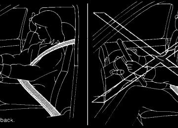
Front facing When you install a child restraint on the 2nd row captain(cid:146)s chairs, follow these steps: 1. Position the child restraint on the seat. It can be placed in a front facing direction, de- pending on the size of the child. Adjust the head restraint to its highest position. Always follow the restraint manufacturer(cid:146)s instruc- tions.
2. Route the seat belt tongue through the child restraint and insert it into the buckle until you hear and feel the latch engage. Be sure to follow the child restraint manu- facturer(cid:146)s instructions for belt routing.
3. Pull on the shoulder belt until all of the belt is fully extended. At this time, the seat belt retractor is in the automatic locking mode (child restraint mode). It reverts back to emergency locking mode when the seat belt is fully retracted.
1-44 Safety(cid:151)Seats, seat belts and supplemental air bags
Z REVIEW COPY:—2004 Pathfinder Armada (wzw) Owners Manual (owners)—USA English (nna) 01/14/04—tbrooks X
After the child restraint is removed and the seat belt is fully retracted, the automatic locking mode (child restraint mode) is canceled.
Front Facing (cid:151) step 4
Front Facing (cid:151) step 5
WRS0146
LRS0350
4. Allow the seat belt to retract. Pull up on the shoulder belt to remove any slack in the belt.
5. Before placing the child in the child restraint, use force to tilt the child restraint from side to side, and tug it forward to make sure that it is securely held in place. It should not move more than 1 inch (25 mm).
6. Check that the retractor is in the automatic locking mode by trying to pull more seat belt out of the retractor. If you cannot pull any more belt webbing out of the retractor, the retractor is in the automatic locking mode.
7. Check to make sure that the child restraint is properly secured prior to each use. If the belt is not locked, repeat steps 3 through 6.
Safety(cid:151)Seats, seat belts and supplemental air bags 1-45
Z REVIEW COPY:—2004 Pathfinder Armada (wzw) Owners Manual (owners)—USA English (nna) 01/14/04—tbrooks X
Rear Facing (cid:151) step 1
Rear Facing (cid:151) step 2
Rear Facing (cid:151) step 3
LRS0352
LRS0353
LRS0354
Rear facing When you install a child restraint on the 2nd row captain(cid:146)s chair, follow these steps: 1. Position the child restraint on the seat. The direction of the child restraint depends on the type of the child restraint and the size of the child. Always follow the restraint manu- facturer(cid:146)s instructions.
2. Route the seat belt tongue through the child restraint and insert it into the buckle until you hear and feel the latch engage. Be sure to follow the child restraint manu- facturer(cid:146)s instructions for belt routing.
3. Pull on the shoulder belt until all of the belt is fully extended. At this time, the seat belt retractor is in the automatic locking mode (child restraint mode). It reverts to emer- gency locking mode when the seat belt is fully retracted.
1-46 Safety(cid:151)Seats, seat belts and supplemental air bags
Z REVIEW COPY:—2004 Pathfinder Armada (wzw) Owners Manual (owners)—USA English (nna) 01/14/04—tbrooks X
7. Check to make sure that the child restraint is properly secured prior to each use. If the belt is not locked, repeat steps 3 through 6.
After the child restraint is removed and the seat belt fully retracted, the automatic locking mode (child restraint mode) is canceled. INSTALLATION ON 2ND ROW BENCH SEATS (if so equipped)
WARNING
c The three-point seat belt in your vehicle is equipped with an automatic locking mode retractor which must be used when installing a child restraint.
c Failure to use the retractor(cid:146)s locking mode will result in the child restraint not being properly secured. The re- straint could tip over or otherwise be unsecured and cause injury to the child in a sudden stop or collision.
Rear Facing (cid:151) step 4
Rear Facing (cid:151) step 5
LRS0355
LRS0356
4. Allow the seat belt to retract. Pull up on the shoulder belt to remove any slack in the belt.
5. Before placing the child in the child restraint, use force to tilt the child restraint from side to side, and tug it forward to make sure that it is securely held in place. It should not move more than 1 inch (25 mm).
6. Check that the retractor is in the automatic locking mode by trying to pull more seat belt out of the retractor. If you cannot pull any more seat belt webbing out of the retractor, the retractor is in the automatic locking mode.
Safety(cid:151)Seats, seat belts and supplemental air bags 1-47
Z REVIEW COPY:—2004 Pathfinder Armada (wzw) Owners Manual (owners)—USA English (nna) 01/14/04—tbrooks X
Front facing (outboard) (cid:151) step 1
Front facing (center) (cid:151) step 1
Front Facing (cid:151) step 2
LRS0376
LRS0377
WRS0250
Front facing When you install a child restraint on the 2nd row bench seat, follow these steps: 1. Position the child restraint on the seat. It can be placed in a front facing direction, de- pending on the size of the child. Adjust the head restraint to its highest position. Always follow the restraint manufacturer(cid:146)s instruc- tions.
2. Route the seat belt tongue through the child restraint and insert it into the buckle until you hear and feel the latch engage. Be sure to follow the child restraint manu- facturer(cid:146)s instructions for belt routing.
1-48 Safety(cid:151)Seats, seat belts and supplemental air bags
Z REVIEW COPY:—2004 Pathfinder Armada (wzw) Owners Manual (owners)—USA English (nna) 01/14/04—tbrooks X
Front Facing (cid:151) step 3
Front Facing (cid:151) step 4
Front Facing (cid:151) step 5
WRS0251
WRS0146
WRS0252
3. Pull on the shoulder belt until all of the belt is fully extended. At this time, the seat belt retractor is in the automatic locking mode (child restraint mode). It reverts back to emergency locking mode when the seat belt is fully retracted.
4. Allow the seat belt to retract. Pull up on the shoulder belt to remove any slack in the belt.
5. Before placing the child in the child restraint, use force to tilt the child restraint from side to side, and tug it forward to make sure that it is securely held in place. It should not move more than 1 inch (25mm).
6. Check that the retractor is in the automatic locking mode by trying to pull more seat belt out of the retractor. If you cannot pull any more belt webbing out of the retractor, the retractor is in the automatic locking mode.
7. Check to make sure that the child restraint is properly secured prior to each use. If the belt is not locked, repeat steps 3 through 6.
Safety(cid:151)Seats, seat belts and supplemental air bags 1-49
Z REVIEW COPY:—2004 Pathfinder Armada (wzw) Owners Manual (owners)—USA English (nna) 01/14/04—tbrooks X
After the child restraint is removed and the seat belt is fully retracted, the automatic locking mode (child restraint mode) is canceled.
Rear facing (outboard) (cid:151) step 1
Rear facing (center) (cid:151) step 1
LRS0373
LRS0375
Rear facing When you install a child restraint on the 2nd row bench seat, follow these steps: 1. Position the child restraint on the seat. The direction of the child restraint depends on the type of the child restraint and the size of the child. Always follow the restraint manu- facturer(cid:146)s instructions.
1-50 Safety(cid:151)Seats, seat belts and supplemental air bags
Z REVIEW COPY:—2004 Pathfinder Armada (wzw) Owners Manual (owners)—USA English (nna) 01/14/04—tbrooks X
Rear Facing (cid:151) step 2
Rear Facing (cid:151) step 3
Rear Facing (cid:151) step 4
WRS0383
WRS0385
WRS0384
2. Route the seat belt tongue through the child restraint and insert it into the buckle until you hear and feel the latch engage. Be sure to follow the child restraint manu- facturer(cid:146)s instructions for belt routing.
3. Pull on the shoulder belt until all of the belt is fully extended. At this time, the seat belt retractor is in the automatic locking mode (child restraint mode). It reverts to emer- gency locking mode when the seat belt is fully retracted.
4. Allow the seat belt to retract. Pull up on the shoulder belt to remove any slack in the belt.
Safety(cid:151)Seats, seat belts and supplemental air bags 1-51
Z REVIEW COPY:—2004 Pathfinder Armada (wzw) Owners Manual (owners)—USA English (nna) 01/14/04—tbrooks X
7. Check to make sure that the child restraint is properly secured prior to each use. If the belt is not locked, repeat steps 3 through 6.
After the child restraint is removed and the seat belt fully retracted, the automatic locking mode (child restraint mode) is canceled. INSTALLATION ON 3RD ROW BENCH SEAT
WARNING
c The three-point seat belt in your vehicle is equipped with an automatic locking mode retractor which must be used when installing a child restraint.
c Failure to use the retractor(cid:146)s locking mode will result in the child restraint not being properly secured. The re- straint could tip over or otherwise be unsecured and cause injury to the child in a sudden stop or collision.
c When installing a child restraint system in the rear center position, both the center seat belt connector tongue and buckle tongue must be secured. See (cid:147)Attaching rear center seat belt(cid:148) earlier in this section.
WRS0386
Rear Facing (cid:151) step 5
5. Before placing the child in the child restraint, use force to tilt the child restraint from side to side, and tug it forward to make sure that it is securely held in place. It should not move more than 1 inch (25mm).
6. Check that the retractor is in the automatic locking mode by trying to pull more seat belt out of the retractor. If you cannot pull any more seat belt webbing out of the retractor, the retractor is in the automatic locking mode.
1-52 Safety(cid:151)Seats, seat belts and supplemental air bags
Front Facing (outboard) (cid:151) step 1
LRS0357
Front facing
WARNING
Front facing child restraints can be in- stalled in all 3rd row bench seat positions. However, front facing child restraints that require the use of a top tether strap can be installed in the center 3rd row position only. Do not install a child restraint requir- ing a top tether strap in an outboard posi- tion and attempt to angle the tether to the 3rd row center anchor.
Z REVIEW COPY:—2004 Pathfinder Armada (wzw) Owners Manual (owners)—USA English (nna) 01/14/04—tbrooks X
Front Facing (center) (cid:151) step 1
Front Facing (cid:151) step 2
Front Facing (cid:151) step 3
LRS0358
WRS0250
WRS0251
When you install a child restraint on the 3rd row bench seat, follow these steps: 1. Position the child restraint on the seat. It can be placed in a front facing direction, de- pending on the size of the child. Adjust the head restraint to its highest position. Always follow the restraint manufacturer(cid:146)s instruc- tions.
2. Route the seat belt tongue through the child restraint and insert it into the buckle until you hear and feel the latch engage. Be sure to follow the child restraint manu- facturer(cid:146)s instructions for belt routing.
3. Pull on the shoulder belt until all of the belt is fully extended. At this time, the seat belt retractor is in the automatic locking mode (child restraint mode). It reverts back to emergency locking mode when the seat belt is fully retracted.
Safety(cid:151)Seats, seat belts and supplemental air bags 1-53
Z REVIEW COPY:—2004 Pathfinder Armada (wzw) Owners Manual (owners)—USA English (nna) 01/14/04—tbrooks X
After the child restraint is removed and the seat belt is fully retracted, the automatic locking mode (child restraint mode) is canceled.
Front Facing (cid:151) step 4
Front Facing (cid:151) step 5
WRS0146
WRS0252
4. Allow the seat belt to retract. Pull up on the shoulder belt to remove any slack in the belt.
5. Before placing the child in the child restraint, use force to tilt the child restraint from side to side, and tug it forward to make sure that it is securely held in place. It should not move more than 1 inch (25mm).
6. Check that the retractor is in the automatic locking mode by trying to pull more seat belt out of the retractor. If you cannot pull any more belt webbing out of the retractor, the retractor is in the automatic locking mode.
7. Check to make sure that the child restraint is properly secured prior to each use. If the belt is not locked, repeat steps 3 through 6.
1-54 Safety(cid:151)Seats, seat belts and supplemental air bags
Z REVIEW COPY:—2004 Pathfinder Armada (wzw) Owners Manual (owners)—USA English (nna) 01/14/04—tbrooks X
Rear Facing (outboard) (cid:151) step 1
Rear Facing (center) (cid:151) step 1
Rear Facing (cid:151) step 2
LRS0362
LRS0388
WRS0383
Rear facing When you install a child restraint on the 3rd row bench seat, follow these steps: 1. Position the child restraint on the seat. The direction of the child restraint depends on the type of the child restraint and the size of the child. Always follow the restraint manu- facturer(cid:146)s instructions.
2. Route the seat belt tongue through the child restraint and insert it into the buckle until you hear and feel the latch engage. Be sure to follow the child restraint manu- facturer(cid:146)s instructions for belt routing.
Safety(cid:151)Seats, seat belts and supplemental air bags 1-55
Z REVIEW COPY:—2004 Pathfinder Armada (wzw) Owners Manual (owners)—USA English (nna) 01/14/04—tbrooks X
Rear Facing (cid:151) step 3
Rear Facing (cid:151) step 4
Rear Facing (cid:151) step 5
WRS0385
WRS0384
WRS0386
3. Pull on the shoulder belt until all of the belt is fully extended. At this time, the seat belt retractor is in the automatic locking mode (child restraint mode). It reverts to emer- gency locking mode when the seat belt is fully retracted.
4. Allow the seat belt to retract. Pull up on the shoulder belt to remove any slack in the belt.
5. Before placing the child in the child restraint, use force to tilt the child restraint from side to side, and tug it forward to make sure that it is securely held in place. It should not move more than 1 inch (25mm).
6. Check that the retractor is in the automatic locking mode by trying to pull more seat belt out of the retractor. If you cannot pull any more seat belt webbing out of the retractor, the retractor is in the automatic locking mode.
1-56 Safety(cid:151)Seats, seat belts and supplemental air bags
Z REVIEW COPY:—2004 Pathfinder Armada (wzw) Owners Manual (owners)—USA English (nna) 01/14/04—tbrooks X
7. Check to make sure that the child restraint is properly secured prior to each use. If the belt is not locked, repeat steps 3 through 6.
After the child restraint is removed and the seat belt fully retracted, the automatic locking mode (child restraint mode) is canceled.
WRS0364
LATCH system anchor point locations 2ndrow captain(cid:146)s chairs (if so equipped) LATCH (Lower Anchors and Tethers for CHildren) SYSTEM
LRS0344
LATCH anchor point labels 2nd row cap-tain(cid:146)s chairs (if so equipped)
Safety(cid:151)Seats, seat belts and supplemental air bags 1-57
Z REVIEW COPY:—2004 Pathfinder Armada (wzw) Owners Manual (owners)—USA English (nna) 01/14/04—tbrooks X
Some child restraints include two rigid or webbing-mounted attachments that can be con- nected to two anchors located at certain seating positions in your vehicle. This system is known as the LATCH (Lower Anchors and Tethers for CHil- dren) system. This system may also be referred to as the ISOFIX or ISOFIX compatible system. With this system, you do not have to use a vehicle seat belt to secure the child restraint. Your vehicle is equipped with special anchor points that are used with LATCH system compatible child re- straints. Check your child restraint for a label stating that it is compatible with the LATCH sys- tem. This information may also be in the child restraint owner(cid:146)s manual. If you have such a child restraint, refer to the illustration for the seating positions equipped with LATCH system anchors which can be used to secure the child restraint. The LATCH system anchors are located at the rear of the seat cushion near the seatback. A label is attached to the seatback to help you locate the LATCH system anchors. LATCH child restraints generally require the use of a top tether strap. See (cid:147)Top tether strap child restraint(cid:148) later in this section for installation in- structions. When installing a child restraint, carefully read and follow the instructions in this manual and those supplied with the child restraint.
WRS0416
LATCH system anchor point locations 2ndrow bench seat (if so equipped)
LRS0382
LATCH anchor point labels 2nd row benchseat (if so equipped)
WARNING
c Attach LATCH system compatible child restraints only at the locations shown. If a child restraint is not secured properly, your child could be seriously injured or killed in an accident.
c The LATCH system anchors are de- signed to withstand only those loads imposed by correctly fitted child re- straints. Under no circumstance are they to be used for adult seat belts or harnesses.
1-58 Safety(cid:151)Seats, seat belts and supplemental air bags
Z REVIEW COPY:—2004 Pathfinder Armada (wzw) Owners Manual (owners)—USA English (nna) 01/14/04—tbrooks X
When you install a LATCH system compatible child restraint to the lower anchor attachments, follow these steps:
WARNING
Inspect the lower anchors by inserting your fingers into the lower anchor area and feeling to make sure there are no obstructions over the LATCH system an- chors, such as seat belt webbing or seat cushion material. The child restraint will not be secured properly if the LATCH sys- tem anchors are obstructed.
insert
1. To install the LATCH system compatible child restraint, the child restraint LATCH system anchor attachments into the anchor points on the seat. If the child re- straint is equipped with a top tether, see (cid:147)Top tether strap child restraint(cid:148) later in this section for installation instructions.
2. After attaching the child restraint and before placing the child in it, use force to tilt the child restraint from side to side and tug it forward to make sure that the child restraint is securely held in place. It should not move more than 1 inch.
3. Check to make sure that the child restraint is
properly secured prior to each use.
TOP TETHER STRAP CHILD RESTRAINT If your child restraint has a top tether strap, it must be secured to the anchor point provided behind its position.
WARNING
Child restraint anchor points are designed to withstand only those loads imposed by correctly fitted child restraints. Under no circumstances are they to be used for adult seat belts or harnesses.
First, secure the child restraint with the seat belt or the LATCH system (2nd row outboard seat positions only), as applicable.
For the 2nd row bench seats (if so equipped) outboard seating positions only, adjust the head restraint to its highest position and route the top tether strap between the head restraint and the top of the seatback. Secure the tether strap to the tether anchor point on the floor directly behind the seat. The center position of the 2nd row bench seat is not equipped with a top tether anchor point.
For the 2nd row captain(cid:146)s chairs (if so equipped), adjust the head restraint to its highest position and route the top tether strap between the head
restraint and the top of the seatback. Secure the tether strap to the tether anchor point on the floor directly behind the seat.
The center position of the 3rd row bench seat is the seating position that can use a top tether strap. The center 3rd row seat position does not have a head restraint. Position the top tether strap over the top of the seatback and secure it to the tether anchor bracket as shown later in this section. Tighten the tether strap according to the manufacturer(cid:146)s instructions to remove any slack.
WARNING
In the 3rd row bench seat, a child restraint with a top tether strap can only be used in the center position. Do not place in an outboard seating position and attempt to angle the tether strap to the center position.
For best child restraint fit, see the child restraint installation instructions in this section and the child restraint manufacturer(cid:146)s instructions. Anchor point locations Anchor points are located on the floor behind the outboard seating positions only for the 2nd row bench seat (if so equipped), on the floor behind the 2nd row captain(cid:146)s chairs (if so equipped) and
Safety(cid:151)Seats, seat belts and supplemental air bags 1-59
Z REVIEW COPY:—2004 Pathfinder Armada (wzw) Owners Manual (owners)—USA English (nna) 01/14/04—tbrooks X
on the floor of the cargo area behind the center seat position on the 3rd row bench seat as shown. If you have any questions when installing a top strap child restraint on the rear seat, consult your NISSAN dealer for details.
WRS0210
Label
Flaps are provided in the carpet for easy access to the anchor points for the 2nd row captain(cid:146)s chairs or 2nd row bench seats and are marked with the label shown.
LRS0340
2nd row captain(cid:146)s chairs (if so equipped) 1. Top tether strap 2. Anchor point1-60 Safety(cid:151)Seats, seat belts and supplemental air bags
Z REVIEW COPY:—2004 Pathfinder Armada (wzw) Owners Manual (owners)—USA English (nna) 01/14/04—tbrooks X
2nd row bench seat (if so equipped)
3rd row bench seat label
3rd row bench seat
LRS0361
LRS0343
LRS0370
1. Top tether strap 2. Anchor point
1. Top tether strap 2. Anchor point
Safety(cid:151)Seats, seat belts and supplemental air bags 1-61
Z REVIEW COPY:—2004 Pathfinder Armada (wzw) Owners Manual (owners)—USA English (nna) 01/14/04—tbrooks X
WRS0417
WRS0256
WRS0378
INSTALLATION ON FRONT PASSENGER SEAT
WARNING
c Never install a rear-facing child re- straint in the front passenger seat. Supplemental front air bags inflate with great force. A rear-facing child restraint could be struck by the supplemental front air bag in a crash and could seri- ously injure or kill your child.
c NISSAN recommends that child re- straints be installed in the rear seat. However, if you must install a forward- facing child restraint in the front pas- senger seat, move the passenger seat to the rearmost position. Also, be sure the front passenger air bag status light is illuminated to indicate the passenger air bag is OFF. See (cid:147)Front passenger air bag and status light(cid:148) earlier in this sec- tion for details.
c A child restraint with a top tether strap should not be used in the front passen- ger seat.
1-62 Safety(cid:151)Seats, seat belts and supplemental air bags
Z REVIEW COPY:—2004 Pathfinder Armada (wzw) Owners Manual (owners)—USA English (nna) 01/14/04—tbrooks X
c The three-point seat belt in your vehicle is equipped with an automatic locking mode retractor which must be used when installing a child restraint.
c Failure to use the retractor(cid:146)s locking mode will result in the child restraint not being properly secured. The re- straint could tip over or otherwise be unsecured and cause injury to the child in a sudden stop or collision. Also, it can change the operation of the front pas- senger air bag. See (cid:147)Front passenger air bag and status light(cid:148) earlier in this section.
WRS0379
WRS0159
Front Facing (cid:151) step 1
If you must install a child restraint in the front seat, follow these steps: 1. Position the child restraint on the front pas- senger seat. It should be placed in a front-facing direction only. Move the seat to the rearmost position. Adjust the head restraint to its highest position. Always follow the child restraint manufacturer(cid:146)s in- structions. Child restraints for infants must be used in the rear-facing direc- tion and therefore must not be used in the front seat.
Front Facing (cid:151) step 2
2. Route the seat belt tongue through the child restraint and insert it into the buckle until you hear and feel the latch engage. Be sure to follow the child restraint manu- facturer(cid:146)s instructions for belt routing.
Safety(cid:151)Seats, seat belts and supplemental air bags 1-63
Z REVIEW COPY:—2004 Pathfinder Armada (wzw) Owners Manual (owners)—USA English (nna) 01/14/04—tbrooks X
Front Facing (cid:151) step 3
Front Facing (cid:151) step 4
Front Facing (cid:151) step 5
WRS0160
WRS0161
WRS0380
3. Pull on the shoulder belt until all of the belt is fully extended. At this time, the seat belt retractor is in the automatic locking mode (child restraint mode). It reverts to emer- gency locking mode when the seat belt is fully retracted.
4. Allow the seat belt to retract slightly. Pull up on the shoulder belt to remove any slack in the belt.
5. Before placing the child in the child restraint, use force to tilt the child restraint from side to side, and tug it forward to make sure that it is securely held in place. It should not move more than 1 inch.
6. Check that the retractor is in the automatic locking mode by trying to pull more seat belt out of the retractor. If you cannot pull any more belt webbing out of the retractor, the retractor is in the automatic locking mode.
1-64 Safety(cid:151)Seats, seat belts and supplemental air bags
Z REVIEW COPY:—2004 Pathfinder Armada (wzw) Owners Manual (owners)—USA English (nna) 01/14/04—tbrooks X
7. Check to make sure the child restraint is properly secured prior to each use. If the seat belt locked, repeat steps 3
through 6.is not
8. Turn the ignition to the ON position. The passenger air bag status light should say (cid:147)OFF(cid:148) . If this light is not illu- minated it may indicate a malfunction. Move the child restraint to another seating position. Have the system checked by a NISSAN dealer.
or
After the child restraint is removed and the seat belt is fully retracted, the automatic locking mode (child restraint mode) is canceled.
Safety(cid:151)Seats, seat belts and supplemental air bags 1-65
Z REVIEW COPY:—2004 Pathfinder Armada (wzw) Owners Manual (owners)—USA English (nna) 01/14/04—tbrooks X
2 Instruments and controls
Instrument panel. . . . . . . . . . . . . . . . . . . . . . . . . . . . . . . . . . . 2-2
Meters and gauges . . . . . . . . . . . . . . . . . . . . . . . . . . . . . . . . 2-3
Speedometer and odometer . . . . . . . . . . . . . . . . . . . . . 2-4
Tachometer . . . . . . . . . . . . . . . . . . . . . . . . . . . . . . . . . . . . 2-5
Engine coolant temperature gauge . . . . . . . . . . . . . . . 2-5
Fuel gauge . . . . . . . . . . . . . . . . . . . . . . . . . . . . . . . . . . . . 2-6
Engine oil pressure gauge . . . . . . . . . . . . . . . . . . . . . . . 2-6
Voltmeter . . . . . . . . . . . . . . . . . . . . . . . . . . . . . . . . . . . . . . 2-7
Automatic transmission fluid temperature gauge (if so equipped) . . . . . . . . . . . . . . . . . . . . . . . . . . 2-7
Compass and outside temperature display . . . . . . . . . . . 2-8
Outside temperature display . . . . . . . . . . . . . . . . . . . . . 2-8
Compass display . . . . . . . . . . . . . . . . . . . . . . . . . . . . . . . 2-9
Warning/indicator lights and audible reminders . . . . . . 2-12
Checking bulbs . . . . . . . . . . . . . . . . . . . . . . . . . . . . . . . 2-12
Warning lights . . . . . . . . . . . . . . . . . . . . . . . . . . . . . . . . 2-13
Indicator lights . . . . . . . . . . . . . . . . . . . . . . . . . . . . . . . . 2-17
Audible reminders . . . . . . . . . . . . . . . . . . . . . . . . . . . . . 2-19
Security systems . . . . . . . . . . . . . . . . . . . . . . . . . . . . . . . . . 2-20
Vehicle security system. . . . . . . . . . . . . . . . . . . . . . . . . 2-20
Nissan vehicle immobilizer system (NVIS) . . . . . . . . 2-21
Windshield wiper and washer switch . . . . . . . . . . . . . . . 2-22
Switch operation . . . . . . . . . . . . . . . . . . . . . . . . . . . . . . 2-22Rear window wiper and washer switch. . . . . . . . . . . . . . 2-23
Rear window and outside mirror defroster switch. . . . . 2-24
Headlight and turn signal switch. . . . . . . . . . . . . . . . . . . . 2-25
Headlight control switch. . . . . . . . . . . . . . . . . . . . . . . . 2-25
Daytime running light system (Canada only) . . . . . . 2-27
Instrument brightness control . . . . . . . . . . . . . . . . . . . 2-27
Turn signal switch . . . . . . . . . . . . . . . . . . . . . . . . . . . . . 2-28
Fog light switch (if so equipped) . . . . . . . . . . . . . . . . 2-28
Hazard warning flasher switch . . . . . . . . . . . . . . . . . . . . . 2-28
Horn . . . . . . . . . . . . . . . . . . . . . . . . . . . . . . . . . . . . . . . . . . . .2-29
Heated seat (if so equipped). . . . . . . . . . . . . . . . . . . . . . . 2-29
Vehicle dynamic control (VDC) off switch (if so equipped) . . . . . . . . . . . . . . . . . . . . . . . . . . . . . . . . . . 2-30
Rear sonar system off switch (if so equipped). . . . . . . . 2-31
Tow mode switch. . . . . . . . . . . . . . . . . . . . . . . . . . . . . . . . . 2-31
Power outlet . . . . . . . . . . . . . . . . . . . . . . . . . . . . . . . . . . . . . 2-32
Cigarette lighter . . . . . . . . . . . . . . . . . . . . . . . . . . . . . . . . . . 2-33
Storage . . . . . . . . . . . . . . . . . . . . . . . . . . . . . . . . . . . . . . . . .2-34
Instrument panel storage trays . . . . . . . . . . . . . . . . . . 2-34
Console box . . . . . . . . . . . . . . . . . . . . . . . . . . . . . . . . . . 2-34
Glove box . . . . . . . . . . . . . . . . . . . . . . . . . . . . . . . . . . . . 2-36
Sunglasses holder . . . . . . . . . . . . . . . . . . . . . . . . . . . . . 2-36
Map pockets . . . . . . . . . . . . . . . . . . . . . . . . . . . . . . . . . . 2-37Z REVIEW COPY:—2004 Pathfinder Armada (wzw) Owners Manual (owners)—USA English (nna) 01/21/04—tbrooks X
Seatback pocket . . . . . . . . . . . . . . . . . . . . . . . . . . . . . . 2-37
Overhead console . . . . . . . . . . . . . . . . . . . . . . . . . . . . . 2-37
Cup holders . . . . . . . . . . . . . . . . . . . . . . . . . . . . . . . . . . 2-38
2nd row center console (if so equipped) . . . . . . . . . 2-41
Cargo area storage bin. . . . . . . . . . . . . . . . . . . . . . . . . 2-42
Luggage hooks. . . . . . . . . . . . . . . . . . . . . . . . . . . . . . . . 2-42
Cargo net (if so equipped). . . . . . . . . . . . . . . . . . . . . . 2-44
Roof rack (if so equipped) . . . . . . . . . . . . . . . . . . . . . . 2-45
Windows . . . . . . . . . . . . . . . . . . . . . . . . . . . . . . . . . . . . . . . .2-46
Power windows . . . . . . . . . . . . . . . . . . . . . . . . . . . . . . . 2-46
Power vent windows (if so equipped) . . . . . . . . . . . . 2-48
Manual vent windows (if so equipped) . . . . . . . . . . . 2-49
Sunroof (if so equipped). . . . . . . . . . . . . . . . . . . . . . . . . . . 2-49
Automatic sunroof . . . . . . . . . . . . . . . . . . . . . . . . . . . . . 2-49
Interior light . . . . . . . . . . . . . . . . . . . . . . . . . . . . . . . . . . . . . . 2-51Console light. . . . . . . . . . . . . . . . . . . . . . . . . . . . . . . . . . 2-52
Personal lights . . . . . . . . . . . . . . . . . . . . . . . . . . . . . . . . . . . 2-52
Map lights . . . . . . . . . . . . . . . . . . . . . . . . . . . . . . . . . . . . . . . 2-53
Cargo light . . . . . . . . . . . . . . . . . . . . . . . . . . . . . . . . . . . . . . 2-53
HomeLinkT universal transceiver (if so equipped). . . . . 2-53
Programming HomeLinkT. . . . . . . . . . . . . . . . . . . . . . . 2-54
Programming HomeLinkT for Canadian customers . . . . . . . . . . . . . . . . . . . . . . . . . . . . . . . . . . . . 2-55
Operating the HomeLinkT universal transceiver. . . . . . . . . . . . . . . . . . . . . . . . . . . . . . . . . . . . 2-55
Programming trouble-diagnosis . . . . . . . . . . . . . . . . . 2-56
Clearing the programmed information . . . . . . . . . . . . 2-56
Reprogramming a single HomeLinkT button . . . . . . 2-56
If your vehicle is stolen . . . . . . . . . . . . . . . . . . . . . . . . . 2-56Z REVIEW COPY:—2004 Pathfinder Armada (wzw) Owners Manual (owners)—USA English (nna) 01/21/04—tbrooks X
INSTRUMENT PANEL
1.
2. 3.
4.
5.
Driver, center and passenger ventila- tors (P. 4-11) Instrument brightness control (P. 2-27) Headlight and turn signal switch (P. 2-25) Steering wheel switch for audio control (if so equipped) (P. 4-38) Driver supplemental air bag/horn (P. 1-14, P. 2-29)
6. Meters, gauges and warning/indicator
7.
lights (P. 2-3, 2-12) Cruise control main/set switches (P. 5-14)
8. Windshield wiper/washer switch and
rear window wiper/washer switch (P. 2-22, P. 2-23) Ignition switch (P. 5-7)
9. 10. Navigation system* (if so equipped)
(P. 4-2)
11. Navigation system* controls (if so
equipped) (P. 4-2)
12. Audio system controls (P. 4-27, 4-32) 13. Front passenger supplemental air bag
(P. 1-14)
14. Glove box (P. 2-36) 15. Climate controls (P. 4-12, 4-21) 16. Aux jack (P. 4-37)
2-2 Instruments and controls
WIC0646
Z REVIEW COPY:—2004 Pathfinder Armada (wzw) Owners Manual (owners)—USA English (nna) 01/14/04—tbrooks X
17. Heated seat switch (if so equipped)
(P. 2-29)
18. Power outlet (P. 2-32) 19. Vehicle dynamic control (VDC) off
switch (P. 2-30)
20. Tow mode switch (P. 2-31) 21. Shift selector lever (P. 5-9) 22. Passenger air bag status light (P. 1-24) 23. Hazard lights (P. 2-28) 24. 4WD shift switch (if so equipped)
(P. 5-17)
25. Tilt steering wheel control (P. 3-16) 26. Rear sonar system off switch
(if so equipped) (P. 2-31)
27. Pedal position adjustment switch
(P. 3-17)
28. Back door open/close switch
(if so equipped) (P. 3-10)
*: Refer to the separate Navigation System Own- er(cid:146)s Manual (if so equipped). See the page number indicated in paren- theses for operating details.
METERS AND GAUGES
1. Warning/indicator lights 2. 3. 4. 5. 6.
Tachometer Speedometer Engine coolant temperature gauge Fuel gauge Engine oil pressure gauge
LIC0540
7.
Automatic transmission fluid tempera- ture gauge (if so equipped)
8. Odometer/Twin trip odometer 9.
Voltmeter
Instruments and controls 2-3
Z REVIEW COPY:—2004 Pathfinder Armada (wzw) Owners Manual (owners)—USA English (nna) 01/14/04—tbrooks X
LIC0541
Speedometer
1. 2. Odometer/twin trip display 3. Change button SPEEDOMETER AND ODOMETER Speedometer The speedometer indicates vehicle speed in miles per hour (MPH) and kilometers per hour (km/h).
2-4 Instruments and controls
Odometer/Twin trip odometer The odometer/twin trip odometer is displayed when the ignition key is in the ON position. The odometer records the total distance the ve- hicle has been driven. The twin trip odometer records the distance of individual trips.
LIC0542
Changing the display: Pushing the change button changes the display as follows: Trip Resetting the trip odometer: Pushing the change button for more than 1 sec- ond resets the trip odometer to zero.
! Odometer only
! Trip
Z REVIEW COPY:—2004 Pathfinder Armada (wzw) Owners Manual (owners)—USA English (nna) 01/14/04—tbrooks X
CAUTION
If the gauge indicates engine coolant tem- perature over the normal range, stop the vehicle as soon as safely possible. If the engine is overheated, continued opera- tion of the vehicle may seriously damage the engine. See (cid:147)If your vehicle over- heats(cid:148) in the (cid:147)In case of emergency(cid:148) sec- tion for immediate action required.
LIC0543
TACHOMETER The tachometer indicates engine speed in revo- lutions per minute (r/min). Do not rev engine into the red zone s1 .
CAUTION
When engine speed approaches the red zone, shift to a higher gear. Operating the engine in the red zone may cause serious engine damage.
LIC0544
ENGINE COOLANT TEMPERATURE GAUGE The gauge indicates the engine coolant tempera- ture. The engine coolant temperature is within the normal range s1 when the gauge needle points within the zone shown in the illustration.The engine coolant temperature varies with the outside air temperature and driving conditions.
Instruments and controls 2-5
Z REVIEW COPY:—2004 Pathfinder Armada (wzw) Owners Manual (owners)—USA English (nna) 01/14/04—tbrooks X
The located on the driver(cid:146)s side of the vehicle.
indicates that the fuel filler lid is
CAUTION
c If
the vehicle runs out of
fuel, malfunction indicator lamp the (MIL) may come on. Refuel as soon as possible. After a few driving trips, the lamp should turn off. If the lamp remains on after a few driving trips, have the vehicle inspected by a NISSAN dealer.
LIC0545
FUEL GAUGE The gauge indicates the approximate fuel level in the tank.
The gauge may move slightly during braking, turning, acceleration, or going up or down hills.
The gauge needle returns to E (Empty) after the ignition key is turned to OFF.
The low fuel warning light comes on when the amount of fuel in the tank is getting low. Refill the fuel tank before the gauge regis- ters E (Empty).
2-6 Instruments and controls
c For additional information, see (cid:147)Mal- function indicator lamp (MIL)(cid:148) later in this section.
LIC0546
ENGINE OIL PRESSURE GAUGE The gauge indicates the engine lubrication sys- tem oil pressure while the engine is running. When the engine speed is high, the engine oil pressure is also high. When it is low, the gauge indicates the low oil pressure.
CAUTION
c This gauge is not designed to indicate low engine oil level. Use the dipstick to check the oil level. (See (cid:147)Engine oil(cid:148) in the (cid:147)Maintenance and do-it-yourself(cid:148) section.)
Z REVIEW COPY:—2004 Pathfinder Armada (wzw) Owners Manual (owners)—USA English (nna) 01/14/04—tbrooks X
c If the gauge needle does not move with the proper amount of engine oil, have the vehicle checked by a NISSAN dealer. Continued vehicle operation in such a condition could cause serious damage to the engine.
LIC0547
VOLTMETER When the ignition key is turned to the ON posi- tion, the voltmeter indicates the battery voltage. When the engine is running, it indicates the gen- erator voltage. While cranking the engine, the volts drop below the normal range. If the needle is not in the normal range (11 - 15 volts) s1 while the engine is running, it may indicate that the charging system is not functioning properly. Have the system checked by a NISSAN dealer.
LIC0548
AUTOMATIC TRANSMISSION FLUID TEMPERATURE GAUGE (if so equipped) This gauge indicates the temperature of the au- tomatic transmission fluid. The automatic trans- mission fluid temperature is in the normal range s1 when the gauge needle points within the zone shown in the illustration.Instruments and controls 2-7
Z REVIEW COPY:—2004 Pathfinder Armada (wzw) Owners Manual (owners)—USA English (nna) 01/14/04—tbrooks X
COMPASS AND OUTSIDE TEMPERATURE DISPLAY
This unit has the following functions: c Measures terrestrial magnetism and indi-
cates heading direction of vehicle c Indicates outside air temperature
CAUTION
c This gauge is not designed to indicate low automatic transmission fluid level. Use the dipstick to check the fluid level. (See (cid:147)5-speed automatic transmission fluid(cid:148) in the (cid:147)Maintenance and do-it- yourself(cid:148) section.)
c If the gauge indicates automatic trans- mission fluid temperature over the nor- mal range, stop the vehicle as soon as safely possible. Have the vehicle checked by a NISSAN dealer. Contin- ued operation of the vehicle may seri- ously damage the transmission.
LIC0583
OUTSIDE TEMPERATURE DISPLAY Push the button when the ignition key is in the ACC or ON position. The outside tempera- ture will be displayed s1 . c To change from (cid:176)F to (cid:176)C, push and hold the button for about 3 seconds until the display begins to flash. Press the button again to toggle between (cid:176)F and (cid:176)C. Once you have selected (cid:176)F or (cid:176)C, the display will continue to flash for about 5 seconds, then the temperature will display.2-8 Instruments and controls
Z REVIEW COPY:—2004 Pathfinder Armada (wzw) Owners Manual (owners)—USA English (nna) 01/14/04—tbrooks X
c When the outside temperature is between 140(cid:176)F (60(cid:176)C) and 194(cid:176)F (90(cid:176)C), the display will read 140(cid:176)F (60(cid:176)C). When the tempera- ture is above 194(cid:176)F (90(cid:176)C), the display will read (cid:147)SC(cid:148).
c When the outside temperature is between than -40(cid:176)F (-40(cid:176)C) and -60(cid:176)F (-51(cid:176)C), the display will read -40(cid:176)F (-40(cid:176)C). When the temperature is below -60(cid:176)F (-51(cid:176)C), the dis- play will read (cid:147)OC(cid:148).
c The outside temperature sensor is located in front of the radiator. The sensor may be affected by road or engine heat, wind direc- tion and other driving conditions. The display may differ from the actual outside tempera- ture or the temperature displayed on various signs or billboards.
c Temperature display will not update unless the vehicle is moving faster than 12 MPH (20 km/h), or the ignition switch has been OFF for 4 hours.
COMPASS DISPLAY Push the button when the ignition key is in the ACC or ON position to display the direction s1 . N: north E: east S: south W: west If the display reads (cid:147)CAL(cid:148), calibrate the compass by driving the vehicle in three complete circles at less than 5 MPH (8 km/h). You can also calibrate the compass by driving your vehicle on your everyday route. The com- pass will be calibrated once it has tracked three complete circles.
Instruments and controls 2-9
Z REVIEW COPY:—2004 Pathfinder Armada (wzw) Owners Manual (owners)—USA English (nna) 01/14/04—tbrooks X
Zone variation change procedure The difference between magnetic north and geo- graphical north is known as variance. In some areas, this difference can sometimes be great enough to cause false compass readings. Follow these instructions to set the variance for your particular location if this happens:
1. Press and hold the
button for about 8
seconds. The current zone number will ap- pear in the display.2. Find your current location on the zone map. Refer to the illustration. Record the zone number.
3. Press and hold the
button until the new zone number appears in the display. After you stop pressing the switch in, the display will show a compass direction within a few seconds.
Inaccurate compass direction:
1. With the display turned on, push the
button about 8 seconds, until the zone se- lection comes up (a number will be dis- played in the mirror compass window).
2. Toggle until correct zone is found and re-
lease button.
Z REVIEW COPY:—2004 Pathfinder Armada (wzw) Owners Manual (owners)—USA English (nna) 01/14/04—tbrooks X
2-10 Instruments and controls
WIC0355
3. The display will return to the normal com- pass mode within 5 seconds of no button activity. If the vehicle changes zone, repeat steps 1
through 3. See map.4.
c If the compass deviates from the correct indication soon after repeated adjustment, have the compass checked at an authorized dealer.
c The compass may not indicate the correct compass point in tunnels or while driving up or down a steep hill. (The compass returns to the correct compass point when the ve- hicle moves to an area where the geomag- netism is stabilized.)
CAUTION
c Do not install a ski rack, antenna, etc., which are attached to the vehicle by means of a magnet. They affect the op- eration of the compass.
c When cleaning the mirror, use a paper towel or similar material dampened with glass cleaner. Do not spray glass cleaner directly on the mirror as it may cause the liquid cleaner to enter the mirror housing.
Instruments and controls 2-11
Z REVIEW COPY:—2004 Pathfinder Armada (wzw) Owners Manual (owners)—USA English (nna) 01/14/04—tbrooks X
WARNING/INDICATOR LIGHTS AND AUDIBLE REMINDERS
or
Anti-lock brake warning light
Low fuel warning light
or
Front passenger air bag status light
Automatic transmission check warning light
Low tire pressure warning light
High beam indicator light (Blue)
Automatic transmission park warning light
model)
Low windshield washer fluid warning light
Malfunction indicator lamp (MIL)
or
Brake warning light
Seat belt warning light and chime
Security indicator light (NVIS)
Charge warning light
Supplemental air bag warning light
Slip indicator light
Check suspension warning light (if so equipped)
Door open warning light
Automatic transmission position indicator light
Cruise main switch indicator light
Transfer 4LO position indicator light
model)
Turn signal/hazard indicator lights
Engine oil pressure low/engine coolant tem- perature high warning light
Cruise set switch indicator light
Vehicle dynamic control off indicator light
4WD warning light (
model)
4WD shift indicator light (
model)
CHECKING BULBS With all doors closed, apply the parking brake and turn the ignition key to the ON position without starting the engine. The following lights will come on:
or
2-12 Instruments and controls
The following lights come on briefly and then go off:
or
If any light fails to come on, it may indicate a burned-out bulb or an open circuit in the electrical system. Have the system repaired promptly.
Z REVIEW COPY:—2004 Pathfinder Armada (wzw) Owners Manual (owners)—USA English (nna) 01/20/04—tmchalpi X
Automatic transmission park model) warning light (
WARNING
c If the ATP light is ON, this indicates that the automatic transmission P (Park) po- sition will not function and the transfer case is in neutral.
c When parking, always make sure that the 4WD shift indicator light illuminates and the parking brake is set. Failure to engage the 4WD shift switch in 2WD, AUTO, 4H or 4LO could result in the vehicle moving unexpectedly, resulting in serious personal injury or property damage.
WARNING LIGHTS
or
Anti-lock brake warning light
If the light comes on while the engine is running, it may indicate the anti-lock brake system is not functioning properly. Have the system checked by a NISSAN dealer. Turn off the engine, and start it again by slowly turning the ignition key (quickly do- ing so may cause the ABS light to stay on when there is nothing wrong). If the light stays on, have the system checked by a NISSAN dealer.
If an abnormality occurs in the system, the anti- lock function ceases, but the regular braking system continues to operate. If the light comes on while you are driving, contact a NISSAN dealer for repair.
Automatic transmission check warning light
When the ignition switch is turned ON, the light comes on for about 2 seconds. If the light blinks for approximately 8 seconds, it may indicate the automatic transmission system is not functioning properly. Have your NISSAN dealer check and repair the transmission, if necessary.
c All mode 4WD: The warning light may come on when the ignition switch is ON and the automatic transmission lever is shifted to the P position while shifting the transfer case between 4H and 4LO. Shift the 4WD shift switch to the 2WD, AUTO, 4H, or 4LO position again to turn off the ATP warning light when the warning light comes on. (Before shift- ing the 4WD switch into the 4LO posi- tion or out of 4LO in the 4H position, move the automatic transmission se- lector lever into the N position.) Shift the selector lever into the P position and make sure that the 4WD shift indi- cator light is ON and the ATP warning light is OFF.)
This light indicates that the automatic transmis- sion parking function is not engaged. If the trans- fer control is not secured in any drive position while the automatic transmission selector lever is in the P (Park) position, the transmission will disengage and the drive wheels will not lock.
or
Brake warning light
This light functions for both the parking brake and the foot brake systems. When the ignition key is in the ON position, the light comes on when the parking brake is applied, Instruments and controls 2-13
Z REVIEW COPY:—2004 Pathfinder Armada (wzw) Owners Manual (owners)—USA English (nna) 01/14/04—tbrooks X
and also warns of a low brake fluid level. If the light comes on while the engine is running with the parking brake not applied, stop the vehicle and perform the following:
1. Check the brake fluid level. Add brake fluid as necessary. See (cid:147)Brake and clutch fluid(cid:148) in the (cid:147)Maintenance and do-it-yourself(cid:148) sec- tion of this manual.
2.
If the brake fluid level is correct, have the brake system checked by a NISSAN dealer.
WARNING
c Your brake system may not be working properly if the warning light is on. Driv- ing could be dangerous. If you judge it to be safe, drive carefully to the nearest service station for repairs. Otherwise, have your vehicle towed because driv- ing it could be dangerous.
c Pressing the brake pedal with the en- gine stopped and/or a low brake fluid level may increase your stopping dis- tance and braking will require greater pedal effort as well as pedal travel.
c If the brake fluid level
is below the MINIMUM or MIN mark on the brake fluid reservoir, do not drive until the brake system has been checked at a NISSAN dealer.
Charge warning light
If this light comes on while the engine is running, it may indicate the charging system is not func- tioning properly. Turn the engine off and check the generator belt. If the belt is loose, broken, missing, or if the light remains on, see a NISSAN dealer immediately.
CAUTION
Do not continue driving if the generator belt is loose, broken or missing.
Check suspension warning light (if so equipped)
This light may indicate a malfunction in the auto- matic load leveling suspension.
For additional information, refer to (cid:147)Jacking up and removing the damaged tire(cid:148) in the (cid:147)In case of emergency(cid:148) section of this manual.
Door open warning light
This light comes on when any of the doors are not closed securely while the ignition key is in the ON position.
Engine oil pressure low/Engine coolant tempera- ture high warning light
This light warns of low engine oil pressure or high engine coolant temperature.
If the light flickers or comes on during normal driving, pull off the road in a safe area, stop the engine and allow it to cool. If the light remains on after checking the oil and coolant, stop the en- gine immediately and call a NISSAN dealer or other authorized repair shop. This light is not designed to indicate a low oil or low coolant level. Check the oil level with the dipstick and check the coolant level on the reservoir. See (cid:147)Engine oil(cid:148) and (cid:147)Checking engine coolant level(cid:148) in the (cid:147)Maintenance and do-it-yourself(cid:148) section of this manual. Also see (cid:147)If your vehicle overheats(cid:148) in the (cid:147)In case of emer- gency(cid:148) section of this manual.
2-14 Instruments and controls
Z REVIEW COPY:—2004 Pathfinder Armada (wzw) Owners Manual (owners)—USA English (nna) 01/14/04—tbrooks X
CAUTION
CAUTION
c Running the engine with the engine oil pressure warning light on could cause serious damage to the engine almost immediately. Such damage is not cov- ered by warranty. Turn off the engine as soon as it is safe to do so.
c If the gauge indicates engine coolant temperature over the normal range, stop the vehicle as soon as safely pos- sible. If the engine is overheated, con- tinued operation of the vehicle may se- riously damage the engine. See (cid:147)If your vehicle overheats(cid:148) in the (cid:147)In case of emergency(cid:148) section for immediate ac- tion required.
4WD warning light ( model)
The 4WD warning light comes on when the key switch is turned to ON. It turns off soon after the engine is started.
If the engine or vehicle is not functioning properly, the warning light will either remain illuminated or blink. See (cid:147)4WD warning light(cid:148) in the (cid:147)Starting and driving(cid:148) section.
c If the warning light comes on or blinks during operation, have your vehicle checked by a NISSAN dealer as soon as possible.
c Do not drive on dry hard surface roads in the 4H or 4LO position. If the 4WD warning light turns on when you are driving on dry hard surface roads: (cid:150) in the AUTO or 4H position, shift the
4WD shift switch to 2WD.
(cid:150) in the 4LO position, stop the vehicle, move the automatic transmission shift selector lever to the N position and shift the 4WD shift switch to 2WD.
c If the warning light is still on after the above operation, have your vehicle checked by a NISSAN dealer as soon as possible.
Low fuel warning light
This light comes on when the fuel level in the fuel tank is getting low. Refuel as soon as it is conve- nient, preferably before the fuel gauge reaches E (Empty). There will be a small reserve of fuel in the tank when the fuel gauge needle reaches E (Empty).
Low tire pressure warning light
This light warns of low tire pressure.
NISSAN(cid:146)s low tire pressure warning system is a tire pressure monitoring system. It monitors tire pressure of all tires except the spare. When the tire pressure monitoring system warning light is lit, one or more of your tires is significantly under- inflated. You should stop and check your tires as soon as possible, and inflate them to the proper pressure as indicated on the vehicle(cid:146)s tire infor- mation placard. Driving on a significantly under- inflated tire causes the tire to overheat and can lead to tire failure. Under-inflation also reduces fuel efficiency and tire tread life, and may affect the vehicle(cid:146)s handling and stopping ability. Each tire, including the spare, should be checked monthly when cold and set to the recommended inflation pressure as specified in the vehicle plac- ard and owner(cid:146)s manual.
The recommended inflation pressure may also be found on the Tire and Loading Information Label. Low tire pressure warning:
If the vehicle is being driven with very low tire pressure (lower than 28 psi, 193 kPa), the light will illuminate and the chime will sound for about 10 seconds.
Instruments and controls 2-15
Z REVIEW COPY:—2004 Pathfinder Armada (wzw) Owners Manual (owners)—USA English (nna) 01/14/04—tbrooks X
For additional information, see (cid:147)Low tire pressure warning system(cid:148) in the (cid:147)Starting and driving(cid:148) section and (cid:147)Low tire pressure warning system(cid:148) in the (cid:147)In case of emergency(cid:148) section.
WARNING
c If the light does not come on with the key switch turned ON, have the vehicle checked by a NISSAN dealer as soon as possible.
c If the light comes on while driving, avoid sudden steering maneuvers or abrupt braking, reduce vehicle speed, pull off the road to a safe location and stop the vehicle as soon as possible. Serious vehicle damage could occur and may lead to an accident and could result in serious personal injury. Check the tire pressure for all four tires. Adjust the tire pressure to the recommended COLD tire pressure shown on the Tire and Loading Information label to turn the low tire pressure warning light OFF. If the light still comes on while driving after adjusting the tire pressure, a tire may be flat. If you have a flat tire, re- place it with a spare tire as soon as possible.
2-16 Instruments and controls
c When a spare tire is mounted or a wheel is replaced, tire pressure will not be indicated and the low tire pressure warning system will not function. Con- tact your NISSAN dealer as soon as possible for tire replacement and/or system resetting.
CAUTION
c The low tire pressure warning system is not a substitute for the regular tire pres- sure check. Be sure to check the tire pressure regularly.
c If the vehicle is being driven at speeds of less than 20 MPH (32 km/h), the low tire pressure warning system may not operate correctly.
c Be sure to install the specified size of
tires to the 4 wheels correctly.
Low windshield washer fluid warning light
This light comes on when the windshield washer fluid is at a low level. Add windshield washer fluid as necessary. See the (cid:147)Maintenance and do-it- yourself(cid:148) section of this manual.
Seat belt warning light and chime
The light and chime remind you to fasten your seat belts. The light illuminates whenever the ignition key is turned to the ON or START position and remains illuminated until the driver(cid:146)s seat belt is fastened. At the same time, the chime sounds for about 6 seconds unless the driver(cid:146)s seat belt is securely fastened.
Refer to (cid:147)Seat belts(cid:148) in the (cid:147)Safety(cid:151)Seats, seat belts and supplemental air bags(cid:148) section for pre- cautions on seat belt usage.
Supplemental air bag warning light
When the ignition key is in the ON or START position, the supplemental air bag warning light illuminates for about 7 seconds and then turns off. This means the system is operational.
the following conditions occur,
If any of the supplemental front air bags, supplemental side air bags (if so equipped), curtain side-impact and rollover air bags, and pre-tensioner seat belt sys- tems need servicing and your vehicle must be taken to a NISSAN dealer: c The supplemental air bag warning light re-
mains on after approximately 7 seconds.
Z REVIEW COPY:—2004 Pathfinder Armada (wzw) Owners Manual (owners)—USA English (nna) 01/14/04—tbrooks X
c The supplemental air bag warning light
flashes intermittently.
c The supplemental air bag warning light does
not come on at all.
Unless checked and repaired, the supplemental restraint system (air bag system) and/or the pre- tensioner seat belts may not function properly. For additional details see (cid:147)Supplemental restraint system(cid:148) in the (cid:147)Safety(cid:151)Seats, seat belts and supplemental air bags(cid:148) section of this manual.
WARNING
If the supplemental air bag warning light is on, it could mean that the supplemental front air bag, supplemental side air bag, curtain side-impact and rollover air bag systems (if so equipped) and/or pre- tensioner seat belt systems will not oper- ate in an accident. INDICATOR LIGHTS
Automatic transmission posi- tion indicator light
When the ignition key is turned to the ON posi- tion, this indicator light shows the automatic transmission selector lever position. See (cid:147)Driving the vehicle(cid:148) in the (cid:147)Starting and driving(cid:148) section of this manual.
Cruise main switch indicator light
or
Front passenger air bag status light
The light comes on when the cruise control main switch is pushed. The light goes out when the main switch is pushed again. When the cruise main switch indicator light comes on, the cruise control system is operational.
Cruise set switch indicator light
The light comes on while the vehicle speed is controlled by the cruise control system. If the light blinks while the engine is running, it may indicate the cruise control system is not functioning prop- erly. Have the system checked by a NISSAN dealer.
4WD shift indicator light
model)
The light should turn off within 1 second after turning the ignition switch to ON.
While the engine is running, the 4WD shift indi- cator light will illuminate the position selected by the 4WD shift switch. The 4WD shift indicator light may blink while shifting from one drive mode to the other.
The front passenger air bag status light ( or ) will be lit and the passenger front air bag will be OFF depending on how the front passenger seat is being used.
For front passenger air bag status light operation, see (cid:147)Front passenger air bag and status light(cid:148) in the (cid:147)Safety (cid:151) Seats, seat belts and supplemental air bags(cid:148) section of this manual.
High beam indicator light (Blue)
This blue light comes on when the headlight high beams are on and goes out when the low beams are selected.
The high beam indicator light also comes on when the passing signal is activated.
Malfunction indicator lamp (MIL)
If this indicator lamp comes on steady or blinks while the engine is running, it may indicate a potential emission control malfunction. The malfunction indicator lamp may also come on steady if the fuel filler cap is loose or missing, or if the vehicle runs out of fuel. Check to make sure Instruments and controls 2-17
Z REVIEW COPY:—2004 Pathfinder Armada (wzw) Owners Manual (owners)—USA English (nna) 01/14/04—tbrooks X
the fuel filler cap is installed and closed tightly, and that the vehicle has at least 3 gallons of fuel in the fuel tank.
After a few driving trips, the lamp should turn off if no other potential emission control system malfunction exists. Operation
The malfunction indicator lamp will come on in one of two ways: c Malfunction indicator lamp on steady (cid:151) An emission control system malfunction has been detected. Check the fuel filler cap. If the fuel filler cap is loose or missing, tighten or install the cap and continue to drive the vehicle. The lamp should turn off after a few driving trips. If the lamp does not turn off after a few driving trips, have the vehicle inspected by a NISSAN dealer. You do not need to have your vehicle towed to the dealer.
c Malfunction indicator lamp blinking (cid:151) An engine misfire has been detected which may damage the emission control system. To re- duce or avoid emission control system dam- age: (cid:150) do not drive at speeds above 45 MPH
(72 km/h).
2-18 Instruments and controls
(cid:150) avoid hard acceleration or deceleration.
(cid:150) avoid steep uphill grades.
(cid:150) if possible, reduce the amount of cargo
being hauled or towed.
The malfunction indicator lamp may stop blinking and come on steady. Have the vehicle inspected by a NISSAN dealer. You do not need to have your vehicle towed to the dealer.
CAUTION
Continued vehicle operation without hav- ing the emission control system checked and repaired as necessary could lead to poor driveability, reduced fuel economy, and possible damage to the emission con- trol system.
Security indicator light (NVIS)
This light blinks whenever the ignition switch is in the LOCK, OFF or ACC position. This function indicates the security system equipped on the vehicle is operational. For additional information, see (cid:147)Security system(cid:148) later in this section.
Slip indicator light
This indicator light will blink when the traction control system is limiting wheel spin. Slippery
road conditions may exist if the slip indicator blinks on. If this happens, adjust your driving accordingly.
The slip indicator light also comes on when you turn the ignition key to the ON position. The light will turn off after about 2 seconds if the system is operational. If the light does not come on or go off, have the traction control system checked by a NISSAN dealer. The system operates in all transmission shift lever positions, but the system can upshift the trans- mission only as high as the indicated shift lever position.
Transfer 4LO position indica- tor light (
model)
The light should turn off within 1 second after turning the ignition switch to ON. This light comes on when the 4WD shift switch is set in the 4LO position with the ignition key in the ON position. If the 4WD shift switch is set in the 4LO position and the light blinks, stop the vehicle, drive slowly forward and the light will turn on. When you shift between 4H and 4LO, stop the vehicle, move the automatic transmission selec- tor lever to the N (Neutral) position, then push the 4WD shift switch and move it to 4LO or 4H.
Z REVIEW COPY:—2004 Pathfinder Armada (wzw) Owners Manual (owners)—USA English (nna) 01/14/04—tbrooks X
Key reminder chime A chime sounds if the driver(cid:146)s door is opened while the key is left in the ignition switch. Remove the key and take it with you when leaving the vehicle. Light reminder chime With the ignition switch in the OFF position, a chime sounds when the driver(cid:146)s door is opened if the headlights or parking lights are on. Turn the headlight control switch off before leav- ing the vehicle.
The transfer case may be damaged if you shift the switch while driving. You cannot move the transfer 4WD shift switch between 4H and 4LO unless you have first stopped the vehicle and moved the automatic transmission shift selector lever to N (Neutral). Make sure the transfer 4LO position indicator light turns on when you shift the 4WD shift switch to 4LO. The indicator light may blink while shifting from one drive mode to the other.
Turn signal/hazard indicator lights
The appropriate light flashes when the turn signal switch is activated. Both lights flash when the hazard switch is turned on.
Vehicle dynamic control off indicator light
This indicator light comes on when the vehicle dynamic control off switch is pushed to OFF. This indicates the vehicle dynamic control system is not operating.
Push the vehicle dynamic control off switch again or restart the engine and the system will operate normally. See (cid:147)Vehicle dynamic control (VDC) system(cid:148) in the (cid:147)Starting and driving(cid:148) section of this manual.
The vehicle dynamic control light also comes on when you turn the ignition key to the ON position. The light will turn off after about 2 seconds if the system is operational. If the light stays on or comes on along with the SLIP indicator light while you are driving, have the vehicle dynamic control system checked by a NISSAN dealer.
While the vehicle dynamic control system is op- erating, you might feel slight vibration or hear the system working when starting the vehicle or ac- celerating, but this is normal. AUDIBLE REMINDERS Brake pad wear warning The front disc brake pads have audible wear warnings. When a front brake pad requires re- placement, it makes a high pitched scraping sound when the vehicle is in motion, whether or not the brake pedal is depressed. Have the brakes checked as soon as possible if the warn- ing sound is heard.
Instruments and controls 2-19
Z REVIEW COPY:—2004 Pathfinder Armada (wzw) Owners Manual (owners)—USA English (nna) 01/14/04—tbrooks X
SECURITY SYSTEMS
LIC0559
Your vehicle has two types of security systems: c Vehicle security system c NISSAN Vehicle Immobilizer System(cid:151)NVIS VEHICLE SECURITY SYSTEM The vehicle security system provides visual and audio alarm signals if parts of the vehicle are disturbed. How to arm the vehicle security sys- tem 1. Close all windows. (The system can be armed even if the windows are open.)2-20 Instruments and controls
2. Remove the key from the ignition switch.
3. Close all doors. Lock all doors. The doors can be locked with the key, power door lock switch or with the keyfob.
Keyfob operation: c Push the
button on the keyfob. All doors lock. The hazard lights flash twice and the horn beeps once to indicate all doors are locked.
c When the
button is pushed with all doors locked, the hazard lights flash twice and the horn beeps once as a re- minder that the doors are already locked.
The horn may or may not beep. Refer to (cid:147)Silencing the horn beep feature(cid:148) (vehicles without navigation system) in the (cid:147)Pre- driving checks and adjustments(cid:148) section or (cid:147)Vehicle electronic systems(cid:148) (vehicles with navigation system) in the (cid:147)Display screen, heater, air conditioner and audio systems(cid:148) section.
4. Confirm that the
indicator light comes light stays on for about 30
on. The seconds. The vehicle security system is now pre-armed. After about 30 seconds the ve- hicle security system automatically shifts into the armed phase. The light begins to flash once every 3 seconds. If, during the 30-second pre-arm time period, the door is unlocked by the key or the keyfob, or the ignition key is turned to ACC or ON, the system will not arm.c If the key is turned slowly when locking the door, the system may not arm. Fur- thermore, if the key is turned beyond the vertical position toward the unlock position to remove the key, the system may be disarmed when the key is re- moved. If the indicator light fails to glow for 30 seconds, unlock the door once and lock it again.
c Even when the driver and/or passen- gers are in the vehicle, the system will arm with all doors closed and locked with the ignition key in the OFF posi- tion.
Z REVIEW COPY:—2004 Pathfinder Armada (wzw) Owners Manual (owners)—USA English (nna) 01/14/04—tbrooks X
Vehicle security system activation The vehicle security system will give the following alarm: c The headlights blink and the horn sounds
intermittently.
c The alarm automatically turns off after ap- proximately 50 seconds. However, the alarm reactivates if the vehicle is tampered with again. The alarm can be shut off by unlocking a door with the key, or by pressing the button on the keyfob. The alarm is activated by: c opening a door without using the key or keyfob (even if the door is unlocked by using the inside lock knob or the power door lock switch).
How to stop an activated alarm The alarm stops only by unlocking a door with the key, or by pressing the button on the key- fob.
NISSAN VEHICLE IMMOBILIZER