- Download PDF Manual
-
236 Battery
X Place the wheel onto the alignment bolt
and push it on.
X Tighten the wheel bolts until they are
finger-tight.
X Unscrew the alignment bolt. X Tighten the last wheel bolt until it is finger-
tight.
Lowering the vehicle G WARNING The wheels could work loose if the wheel nuts and bolts are not tightened to the specified tightening torque. There is a risk of accident. Have the tightening torque immediately checked at a qualified specialist workshop after a wheel is changed.
X Turn the crank of the jack counter-
clockwise until the vehicle is once again standing firmly on the ground.
X Place the jack to one side.
X Tighten the wheel bolts evenly in a crosswise pattern in the sequence
indicated (: to A). The specified tightening torque is 133 lb-ft(180 Nm).
X Turn the jack back to the out-of-use
position and stow it in the trunk again with the rest of the wheel-changing tools.
Battery Important safety notes Special tools and expert knowledge are required when working on the battery, e.g. removal and installing. You should therefore have all work involving the battery carried out at a qualified specialist workshop. G WARNING Work carried out incorrectly on the battery can, for example, lead to a short circuit and damage your vehicle's electronic system. This can disrupt driving safety systems such as ABS (anti-lock braking system) or ESP® (Electronic Stability Program). RIf ABS malfunctions, the wheels can lock during braking. This limits the steerability of the vehicle when braking and the braking distance may increase. There is a risk of accident.
RIf ESP® malfunctions, the vehicle will not be stabilized if it starts to skid or a wheel starts to spin. There is a risk of accident.
You should therefore have all work involving the battery carried out at a qualified specialist workshop. G WARNING Electrostatic build-up can lead to the creation of sparks, which could ignite the highly explosive gases of a battery. There is a risk of an explosion. Before handling the battery, touch the vehicle body to remove any existing electrostatic build-up.
The highly flammable gas mixture forms when charging the battery as well as when jump- starting. Always make sure that neither you nor the battery is electrostatically charged. A build- up of electrostatic charge can be caused, for example: Rby wearing clothing made from synthetic
fibers
Rdue to friction between clothing and seats Rif you push or pull the battery across the
carpet or other synthetic materials Rif you wipe the battery with a cloth. G WARNING During the charging process, a battery produces hydrogen gas. If a short circuit occurs or sparks are created, the hydrogen gas can ignite. There is a risk of an explosion. RMake sure that the positive terminal of a
connected battery does not come into contact with vehicle parts.
RNever place metal objects or tools on a
battery.
RIt is important that you observe the
described order of the battery terminals when connecting and disconnecting a battery.
RWhen jump-starting, make sure that the battery poles with identical polarity are connected.
RIt is particularly important to observe the
described order when connecting and disconnecting the jumper cables.
RNever connect or disconnect the battery
terminals while the engine is running. G WARNING Battery acid is caustic. There is a risk of injury. Avoid contact with the skin, eyes or clothing. Do not inhale any battery gases. Do not lean over the battery. Keep children away from batteries. Wash battery acid immediately with water and seek medical attention.
Battery
237
H Environmental note
Batteries contain dangerous substances. It is against the law to dispose of them with the household rubbish. They must be collected separately and recycled to protect the environment. Dispose of batteries in an environmentally friendly manner. Take discharged batteries to a qualified specialist workshop or a special collection point for used batteries.
! Have the battery checked regularly at a
qualified specialist workshop. Observe the service intervals in the Maintenance Booklet or contact a qualified specialist workshop for more information.
! You should have all work involving the
battery carried out at a qualified specialist workshop. In the exceptional case that it is necessary for you to disconnect the battery yourself, make sure that: Ryou switch off the engine and remove the
SmartKey. On vehicles with KEYLESS- GO, ensure that the ignition is switched off. Check that all the indicator lamps in the instrument cluster are off. Otherwise, electronic components, such as the alternator, may be damaged.
Ryou first remove the negative terminal clamp and then the positive terminal clamp. Never swap the terminal clamps. Otherwise, the vehicle's electronic system may be damaged.
Rthe transmission is locked in position P
after disconnecting the battery. The vehicle is secured against rolling away. You can then no longer move the vehicle.
The battery and the cover of the positive terminal clamp must be installed securely during operation.
238 Battery
Comply with safety precautions and take protective measures when handling batteries.
Risk of explosion.
Fire, open flames and smoking are prohibited when handling the battery. Avoid creating sparks. Battery acid is caustic. Avoid contact with skin, eyes or clothing. Wear suitable protective clothing, especially gloves, apron and faceguard. Rinse any acid spills immediately with clear water. Contact a physician if necessary. Wear eye protection.
Keep children away.
Observe this Operator's Manual.
For safety reasons, Mercedes-Benz recommends that you only use batteries which have been tested and approved for your vehicle by Mercedes-Benz. These batteries provide increased impact protection to prevent vehicle occupants from suffering acid burns should the battery be damaged in the event of an accident. In order for the battery to achieve the maximum possible service life, it must always be sufficiently charged. The vehicle battery, like other batteries, can discharge over time if you do not use the vehicle. In this case, have the battery disconnected at a qualified specialist workshop. You can also charge the battery with a charger recommended by Mercedes-
Benz. Contact a qualified specialist workshop for further information. Have the battery condition of charge checked more frequently if you use the vehicle mainly for short trips or if you leave it standing idle for a lengthy period. Consult a qualified specialist workshop if you wish to leave your vehicle parked for a long period of time. i Remove the SmartKey if you park the vehicle and do not require any electrical consumers. The vehicle will then use very little energy, thus conserving battery power.
i If the battery power supply has been interrupted, e.g. if the battery was fully discharged, you will need to reset the "exterior mirrors automatic folding function", by folding the mirrors out once (Y page 88).
Charging the battery G WARNING During charging and jump-starting, explosive gases can escape from the battery. There is a risk of an explosion. Particularly avoid fire, open flames, creating sparks and smoking. Ensure there is sufficient ventilation while charging and jump-starting. Do not lean over a battery. G WARNING Battery acid is caustic. There is a risk of injury. Avoid contact with the skin, eyes or clothing. Do not inhale any battery gases. Do not lean over the battery. Keep children away from batteries. Wash battery acid immediately with water and seek medical attention. G WARNING A discharged battery can freeze at temperatures below freezing point. When jump-starting the vehicle or charging the battery, gases can escape from the battery. There is a risk of an explosion.
Allow the frozen battery to thaw out before charging it or jump-starting.
! Only use battery chargers with a
maximum charging voltage of 14.8 V.
! Only charge the battery using the jump-
starting connection point.
The jump-starting connection point is in the engine compartment (Y page 240). Never charge the battery if it is still installed in the vehicle, unless you use a battery charger which has been tested and approved by Mercedes-Benz. A battery charger unit specially adapted for Mercedes-Benz vehicles and tested and approved by Mercedes-Benz is available as an accessory. It permits the charging of the battery in its installed position. Contact an authorized Mercedes- Benz Center for further information and availability. Charge the battery in accordance with the separate instructions for the accessory battery charger. Read the battery charger's operating instructions before charging the battery. X Open the hood (Y page 214). X Connect the battery charger to the positive
terminal and ground point in the same order as when connecting the donor battery in the jump-starting procedure (Y page 240).
Battery
239
240
Jump-starting
Jump-starting G WARNING Battery acid is caustic. There is a risk of injury. Avoid contact with the skin, eyes or clothing. Do not inhale any battery gases. Do not lean over the battery. Keep children away from batteries. Wash battery acid immediately with water and seek medical attention. G WARNING During charging and jump-starting, explosive gases can escape from the battery. There is a risk of an explosion. Particularly avoid fire, open flames, creating sparks and smoking. Ensure there is sufficient ventilation while charging and jump-starting. Do not lean over a battery. G WARNING During the charging process, a battery produces hydrogen gas. If a short circuit occurs or sparks are created, the hydrogen gas can ignite. There is a risk of an explosion. RMake sure that the positive terminal of a connected battery does not come into contact with
vehicle parts.
RNever place metal objects or tools on a battery. RIt is important that you observe the described order of the battery terminals when connecting
and disconnecting a battery.
RWhen jump-starting, make sure that the battery poles with identical polarity are connected. RIt is particularly important to observe the described order when connecting and disconnecting
the jumper cables.
RNever connect or disconnect the battery terminals while the engine is running. G WARNING A discharged battery can freeze at temperatures below freezing point. When jump-starting the vehicle or charging the battery, gases can escape from the battery. There is a risk of an explosion. Allow the frozen battery to thaw out before charging it or jump-starting. G WARNING Non-combusted fuel can collect in the exhaust system and ignite. There is a risk of fire. Avoid repeated and lengthy starting attempts.
! Avoid repeated and lengthy starting attempts. Otherwise, the catalytic converter could be
damaged by the non-combusted fuel.
Do not start the vehicle using a rapid charging device. If your vehicle's battery is discharged, the engine can be jump-started from another vehicle or from a second battery using jumper cables. Observe the following points: RThe battery is not accessible in all vehicles. If the other vehicle's battery is not accessible,
jump-start the vehicle using a second battery or a jump-starting device.
RYou may only jump-start the vehicle when the engine and exhaust system are cold.
Jump-starting 241
RDo not start the engine if the battery is frozen. Let the battery thaw first. ROnly jump-start from batteries with a 12 V voltage rating. ROnly use jumper cables which have a sufficient cross-section and insulated terminal clamps. RIf the battery is fully discharged, leave the battery that is being used to jump-start connected
for a few minutes before attempting to start. This charges the battery slightly.
RMake sure that the two vehicles do not touch. Make sure that: Rthe jumper cables are not damaged. Rwhen the jumper cables are connected to the battery, uninsulated sections of the terminal
clamp do not come into contact with other metal sections.
Rthe jumper cables cannot come into contact with parts such as the V-belt pulley or the fan.
These parts move when the engine is started and while it is running.
X Press the electric parking brake handle. X Shift the transmission to P with the button in the center console. X Remove the SmartKey from the ignition lock. X Switch off all electrical consumers (e.g. radio, blower, etc.). X Open the hood (Y page 214).
Position number B identifies the charged battery of the other vehicle or an equivalent jump- starting device. X Slide cover A of positive terminal : in the direction of the arrow. X Connect positive terminal : on your vehicle to positive terminal ; of donor battery B
using the jumper cable, beginning with your own battery.
X Start the engine of the donor vehicle and run it at idling speed.
242 Towing and tow-starting
X Connect negative terminal = of donor battery B to earth point ? of your vehicle using
the jumper cable, connecting the jumper cable to donor battery B first.
X Start the engine. X Before disconnecting the jumper cables, let the engine run for several minutes. X First, remove the jumper cables from earth point ? and negative terminal =, then from positive clamp : and positive terminal ;. Each time beginning with your vehicle's battery.
X Slide cover A of the positive terminal in the opposite direction to the arrow. X Have the battery checked at a qualified specialist workshop. i Jump-starting is not considered to be a normal operating condition. i Jumper cables and further information regarding jump-starting can be obtained at any
qualified specialist workshop.
Towing and tow-starting Important safety notes If the vehicle can no longer be driven because of an accident or breakdown, you have the following options: Rtransporting the vehicle
As a rule, you should have the vehicle transported.
Rtowing the vehicle with the rear axle raised
Only tow the vehicle with the rear axle raised in exceptional cases.
Rtowing the vehicle with a tow rope or tow
bar Only tow the vehicle in exceptional cases. The engine must be running if you tow the vehicle with a tow rope or tow bar. Observe the following notes. G WARNING The rear axle locks when: Rthe engine is not running Rthe engine stalls while the vehicle is being
towed
Rthere is a malfunction in the power supply
or the vehicle's electrical system
There is a risk of an accident. In the event of a breakdown, you should always have the vehicle transported.
G WARNING If the brake system or power steering is malfunctioning and your vehicle is then towed away, significantly more effort may be required to steer and brake than is normally required. There is a risk of an accident. In such cases, use a tow bar. Before towing, make sure that the steering moves freely.
! Use the SmartKey instead of the Start/
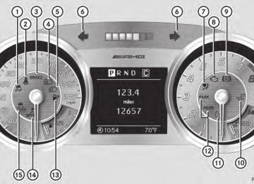
Stop button when towing the vehicle. Start the engine and keep it running. Turn the SmartKey to position 2 in the ignition. Set the transmission to N using the E- SELECT lever. Make sure that you then leave the SmartKey in position 2. Check the transmission position in the instrument cluster.
! Make sure that the electric parking brake is released. If the electric parking brake is faulty, visit a qualified specialist workshop. Mercedes-Benz recommends that you use an authorized Mercedes-Benz Center for this purpose.
! When towing, pull away slowly and
smoothly. If the tractive power is too high, the vehicles could be damaged.
! Only secure the tow rope or tow bar at the towing eyes. Otherwise, the vehicle could be damaged.
! Do not use the towing eye for recovery,
as this could damage the vehicle. If in doubt, recover the vehicle with a crane.
! You may only tow the vehicle a maximum
distance of 30 miles (50 km). A towing speed of 30 mph (50 km/h) must not be exceeded. For towing distances over 30 miles (50 km), the vehicle must loaded onto a transporter.
! Do not tow with sling-type equipment.
This could damage the vehicle.
! Tow-starting the vehicle is not permitted.
The transmission may otherwise be damaged.
Also observe the following notes: RIf the engine does not start, try jump-
starting it (Y page 240). Tow-starting the vehicle is not permitted.
RIf it is not possible to jump-start the vehicle, have it transported to the nearest qualified specialist workshop, e.g. an authorized Mercedes-Benz Center.
RIf the vehicle has transmission damage,
have it transported to a qualified specialist workshop. Observe the display messages in the instrument cluster.
Installing/removing the towing eye Installing the towing eye X Take the towing eye and the wheel
wrench12 out of the wheel-change tool kit (Y page 228).
The bracket for the removable towing eye is in the bumper at the front. It is located under the cover.
Towing and tow-starting 243
X Pull out cover : forwards. X Take cover : off the opening.
Removing the towing eye X Take the lug wrench12 from the wheel-
change tool kit (Y page 228).
X Insert the lug wrench handle into the
towing eye and turn it counter-clockwise.
X Unscrew the towing eye. X Attach cover : to the bumper and press
until it engages.
X Return the towing eye and the lug wrench
to the wheel-change tool kit.
Towing the vehicle with the rear axle raised When towing your vehicle with the rear axle raised, it is important that you observe the safety instructions (Y page 242). Only tow the vehicle with the rear axle raised in exceptional cases. ! The engine must be switched off
(SmartKey in ignition lock in position 0 or position 1) if the vehicle is being towed with the rear axle raised or if the parking brake is being tested on a dynamometer. Intervention by ESP® could otherwise damage the brake system.
12 Not included in the scope of delivery.
244 Fuses
X Switch on the hazard warning lamps
(Y page 94).
X Make sure that the SmartKey is in position
2 in the ignition and that the engine is running throughout the towing procedure.
X Move the transmission to N with the E- SELECT lever. Check the transmission position in the instrument cluster.
Towing a vehicle with both axles on the ground When having your vehicle towed, observe the important safety notes (Y page 242). X Switch on the hazard warning lamps
(Y page 94).
i When towing with the hazard warning lamps switched on, use the combination switch as usual to signal a change of direction. In this case, only the turn signals for the desired direction flash. When the combination switch is reset, the hazard warning lamps start flashing again.
X Insert the SmartKey into the ignition lock
(Y page 113).
X Start the engine and leave the SmartKey in
X Move the transmission to N with the E-
the ignition.
SELECT lever.
X Check the transmission position in the
instrument cluster display (Y page 119).
X Leave the engine running during the entire
towing procedure.
Transporting the vehicle The towing eye can be used to pull the vehicle onto a trailer or transporter for transporting purposes. ! Only lash the vehicle down by the wheels or wheel rims, not by parts of the vehicle such as axle or steering components. Otherwise, the vehicle could be damaged.
X Start the engine. X Make sure that the SmartKey is in position
2 in the ignition and that the engine is running during the entire loading operation.
X Move the transmission to N with the E- SELECT lever. Check the transmission position in the instrument cluster. As soon as the vehicle is loaded: X Prevent the vehicle from rolling away by
applying the electric parking brake.
X Shift the transmission to P with the button
in the center console.
X Turn the SmartKey to position 0 in the ignition lock and remove the SmartKey from the ignition lock.
X Secure the vehicle.
Fuses Important safety notes G WARNING Only use fuses approved by Mercedes-Benz with the specified amperage for the system in question and do not attempt to repair or bridge a blown fuse. Using other than approved fuses or using repaired or bridged fuses may cause an overload leading to a fire, and/or cause damage to electrical components and/or systems. Have the cause determined and remedied by an authorized Mercedes-Benz Center.
! Only use fuses that have been approved
for Mercedes-Benz vehicles and which have the correct fuse rating for the system concerned. Otherwise, components or systems could be damaged.
The fuses in your vehicle serve to close down faulty circuits. If a fuse blows, all the components on the circuit and their functions stop operating. Blown fuses must be replaced with fuses of the same rating, which you can recognize by the color and value. The fuse ratings are listed
in the fuse allocation chart. An authorized Mercedes-Benz Center will be happy to advise you. i If a fuse has blown, contact a breakdown
service or an authorized Mercedes-Benz Center.
If the newly inserted fuse also blows, have the cause traced and rectified at a qualified specialist workshop, e.g. an authorized Mercedes-Benz Center.
Before changing a fuse X Park the vehicle and apply the electric
parking brake.
X Switch off all electrical consumers. X Remove the SmartKey from the ignition
lock.
The fuses are located in various fuse boxes: Rfuse box in the footwell on the front-
passenger side
Rfuse box in the rear The "Relay and fuse information sheet" is located with the wheel-change toolkit in the trunk.
Fuse box in the footwell
Fuses
245
X To close: install the floor panel again. X Screw in and tighten screws :. X Put in the carpet and press to secure. ! The floor panel must be installed properly, otherwise moisture or dirt could impair the function of the fuses.
Fuse box in the rear Coupe
X To open: open the trunk. X Fold cover : in the center of the rear wall
down in the direction of the arrow.
X To close: fold cover : up in the opposite direction to the arrow and press to secure.
! The cover must be installed properly,
otherwise moisture or dirt could impair the function of the fuses.
Roadster
X To open: remove the carpet over the
footrest.
X Loosen screws : on the floor panel using
a suitable tool.
X Remove the floor panel.
246 Fuses
X To open: from the vehicle interior, lift up
cover : between the roll bars in the direction of the arrow.
X To close: shut cover : in the opposite
direction to the arrow and press to secure.
! The cover must be installed properly,
otherwise moisture or dirt could impair the function of the fuses.
247
Useful information ............................ 248
Important safety notes .................... 248
Operation ........................................... 248
Winter operation ............................... 250
Tire pressure ..................................... 251
Loading the vehicle .......................... 258
Maximum load rating ....................... 261
Uniform Tire Quality Grading Standards .......................................... 261
Tire labeling ....................................... 263
Definition of terms for tires and loading ............................................... 266
Changing a wheel ............................. 269
Wheel and tire combinations ........... 270248 Operation
Useful information
i This Operator's Manual describes all models and all standard and optional equipment of your vehicle available at the time of publication of the Operator's Manual. Country-specific differences are possible. Please note that your vehicle may not be equipped with all features described. This also applies to safety- related systems and functions.
i Please read the information on qualified
specialist workshops (Y page 22).
Important safety notes
Consult an authorized Mercedes-Benz Center if you require information on approved and recommended tires and wheels for summer and winter operation. Advice on purchasing and caring for tires is also available there. G WARNING Replace rims or tires with the same designation, manufacturer and type as shown on the original part. For further information contact an authorized Mercedes-Benz Center. If incorrectly sized rims and tires are mounted, the wheel brakes or suspension components can be damaged. Also, the operating clearance of the wheels and the tires may no longer be correct. G WARNING Worn, old tires can cause accidents. If the tire tread is worn to minimum tread depth, or if the tires have sustained damage, replace them. When replacing rims, only use genuine Mercedes-Benz wheel bolts specified for the particular rim type. Failure to do so can result in the bolts loosening and possibly an accident. Retreaded tires are not tested or recommended by Mercedes-Benz, since previous damage cannot always be
recognized on retreads. The operating safety of the vehicle cannot be assured when such tires are used. G WARNING If you feel a sudden significant vibration or ride disturbance, or you suspect that possible damage to your vehicle has occurred, you should turn on the hazard warning flashers, carefully slow down, and drive with caution to an area which is a safe distance from the road. Inspect the tires and the vehicle underbody for possible damage. If the vehicle appears unsafe, have the vehicle towed to the nearest authorized Mercedes-Benz Center or tire dealer for repairs. G WARNING Do not drive with a flat tire. A flat tire affects the ability to steer or brake the vehicle. You might lose control of the vehicle. Continued driving with a flat tire or driving at high speed with a flat tire will cause excessive heat build- up and possibly a fire.
i Further information about tires and
wheels can be obtained from any authorized Mercedes-Benz Center.
Operation Notes on driving RIf the vehicle is heavily loaded, check the
tire pressures and correct them if necessary.
RWhen parking your vehicle, make sure that the tires do not get deformed by the curb or other obstacles. If it is necessary to drive over curbs, speed humps or similar elevations, try to do so slowly and at an obtuse angle. Otherwise, the tires, particularly the sidewalls, may be damaged.
Notes on high performance tires G WARNING Due to the special tire tread in combination with the optimized rubber compound, there is an increased risk of hydroplaning and skidding on a damp or wet road surface. tire grip is also noticeably reduced at low outside temperatures and low tire operating temperatures. There is a risk of an accident. Turn on ESP® and adapt your driving style accordingly. When the outside temperature falls below 10 †, use M+S tires.
i Different driving styles may lead to high
tire wear and the tires may reach the minimum tire tread depth after only a short time.
Notes on regularly inspecting wheels and tires G WARNING Regularly check the tires for damage. Damaged tires can cause tire inflation pressure loss. As a result, you could lose control of your vehicle. Worn, old tires can cause accidents. If the tire tread is worn to minimum tread depth, or if the tires have sustained damage, replace them.
RRegularly check the wheels and tires of
your vehicle for damage (e.g. cuts, punctures, tears, bulges on tires and deformation or cracks or severe corrosion on wheels) at least once a month, as well as after driving off-road or on rough roads. Damaged wheels can cause a loss of tire pressure.
RRegularly check the tire tread depth and
the condition of the tread across the whole width of the tire (Y page 249). If necessary, turn the front wheels to full lock in order to inspect the inner side of the tire surface.
Operation 249
RAll wheels must have a valve cap to protect the valve against dirt and moisture. Do not install anything on the valve (such as tire pressure monitoring systems) other than the standard valve cap or other valve caps approved by Mercedes-Benz for your vehicle.
RRegularly check the pressure of all the tires including the emergency spare wheel or the spare wheel, particularly prior to long trips, and correct the pressure as necessary (Y page 251).
Tire tread G WARNING Although the applicable federal motor vehicle safety laws consider a tire to be worn when the tread wear indicators (TWI) become visible at approximately 1/16 in (1.6 mm), we recommend that you do not allow your tires to wear down to that level. As tread depth approaches 1/8 in (3 mm), the adhesion properties on a wet road are sharply reduced. Depending upon the weather and/or road surface (conditions), the tire traction varies widely.
Do not use tires until they are excessively worn as the tire traction on wet road surfaces decreases significantly when the tread depth is less than 1/8 in (3 mm). Treadwear indicators (TWI) are required by law. Six indicators are positioned on the tire tread. They are visible once the tread depth is approximately 1/16 in (1.6 mm). If this is the case, the tire is so worn that it must be replaced. The recommended tread depth for summer tires is at least 1/8 in (3 mm). The recommended tread depth for winter tires is at least 1/6 in (4 mm).
250 Winter operation
Bar indicator : for tread wear is integrated into the tire tread.
Notes on selecting, mounting and replacing tires ROnly mount tires and wheels of the same
type and make.
ROnly mount tires of the correct size onto
the wheels.
RAfter mounting new tires, break them in at
moderate speeds for the first 60 miles (100 km), as they only reach their full performance after this distance.
RDo not use tires until they are excessively
worn as the tire traction on wet road surfaces decreases significantly when the tread depth is less than 1/8 in (3 mm). RReplace the tires after six years at the
latest, regardless of wear. This also applies to the spare wheel/emergency spare wheel.
The service life of tires depends on the following factors amongst other things: RDriving style RTire pressure RDistance covered
Winter operation General notes Have your vehicle winterproofed at a qualified specialist workshop at the onset of winter.
Observe the notes in the "Changing a wheel" section (Y page 269).
Driving with summer tires At temperatures below 45 ‡ (+7 †), summer tires lose elasticity and therefore traction and braking power. Change the tires on your vehicle to M+S tires. Using summer tires at very cold temperatures could cause cracks to form, thereby damaging the tires permanently. Mercedes-Benz cannot accept responsibility for this type of damage.
Snow chains G WARNING If snow chains are installed to the front wheels, they may drag against the vehicle body or chassis components. This could cause damage to the vehicle or the tires. There is a risk of an accident. To avoid hazardous situations: Rnever install snow chains to the front
wheels
Ralways install snow chains in pairs to the
rear wheels.
! There is not enough space for snow
chains on some wheel sizes. Observe the information under "Tires and wheels" in the "Technical Data" section to avoid damage to the vehicle or the wheels.
For safety reasons, Mercedes-Benz recommends that you only use snow chains that have been specially approved for your vehicle by Mercedes-Benz, or are of a corresponding standard of quality. RYou may not mount snow chains to all
wheel-tire combinations; see the information under "Wheels and tires" in the "Technical data" section.
ROnly use snow chains when driving on
roads completely covered by snow. Remove the snow chains as soon as
possible when you come to a road that is not snow-covered.
RLocal regulations may restrict the use of
snow chains. Observe the appropriate regulations if you wish to mount snow chains.
RDo not exceed the maximum permissible
speed of 30 mph (50 km/h).
RSnow chains must not be mounted on
emergency spare wheels.
i You may wish to deactivate
ESP®(Y page 56) when pulling away with snow chains installed. You can thereby allow the wheels to spin in a controlled manner, achieving an increased driving force (cutting action).
M+S tires G WARNING M+S tires with a tread depth of less than 1/6
inch (4 mm) must be replaced. They are no longer suitable for winter operation. G WARNING If you mount the spare wheel when driving with M+S tires, bear in mind that driving stability will be impaired due to unstable cornering characteristics caused by the different tire characteristics. Adapt your style of driving accordingly. Have the spare wheel replaced by a normal wheel with an M+S tire at the nearest Mercedes-Benz Center.At temperatures below 45 ‡ (+7 †), use all- season tires or winter tires. Both types of tire are identified by the M+S marking. Only winter tires bearing the i snowflake symbol in addition to the M+S marking provide the best possible grip in wintry road conditions. Only these tires will allow driving safety systems such as ABS and ESP® to function optimally in winter. This is because
Tire pressure 251
these tires were specifically developed for driving in snow. Use M+S tires of the same make and tread on all wheels to maintain safe handling characteristics. Always observe the maximum permissible speed specified for the M+S tires you have mounted. When you have mounted the M+S tires: X Check the tire pressures (Y page 251). X Restart the tire pressure monitor
(Y page 257).
Tire pressure Tire pressure specifications G WARNING Follow recommended tire inflation pressures. Do not underinflate tires. Underinflated tires wear excessively and/or unevenly, adversely affect handling and fuel economy, and are more likely to fail from being overheated. Do not overinflate tires. Overinflated tires can adversely affect handling and ride comfort, wear unevenly, increase stopping distance, and result in sudden deflation (blowout) because they are more likely to become punctured or damaged by road debris, potholes etc. Do not overload the tires by exceeding the specified load limit as indicated on the Tire and Loading Information placard on the driver's door B-pillar. Overloading the tires can overheat them, possibly causing a blowout. Overloading the tires can also result in handling or steering problems, or brake failure.
You will find a table of recommended tire pressures on the Tire and Loading Information placard on the B-pillar on the driver's side (Y page 258). You will find a table of tire pressure for various operating conditions on the inside of your vehicle's fuel filler flap.
252 Tire pressure
To test tire pressure, use a suitable pressure gauge. The outer appearance of a tire does not permit any reliable conclusion about the tire pressure. On vehicles equipped with the electronic tire pressure monitor, the tire pressure can be checked in the on-board computer. G WARNING Should the tire pressure drop repeatedly: Rcheck the tire for foreign bodies. Rcheck whether the wheel is losing air or the
valve is leaking.
Rmake sure that only a valve cap approved by Mercedes-Benz is installed on the tire valve.
Tire pressures that are too low have a negative effect on vehicle safety, which could lead you to cause an accident.
Only correct tire pressures when the tires are cold. The tires are cold when the vehicle has been parked for at least three hours or driven for less than 1 mile (1.6 km). The tire temperature changes depending on the outside temperature, the vehicle speed and the tire load. If the tire temperature changes by 18 ‡ (10 †), the tire pressure changes by approximately 10 kPa (0.1 bar/1.5 psi). Take this into account when checking the pressure of warm tires and only correct the tire pressure if it is too low for the current operating conditions. If you check the tire pressure when the tires are warm, the resulting value will be higher than if the tires were cold. This is normal. Do not reduce the tire pressure to the value specified for cold tires. The tire pressure would otherwise be too low. Observe the recommended tire pressure specifications for cold tires on the Tire and Loading Information placard on the B-pillar on the driver's side. i The specifications given on the following Tire and Loading Information placard are examples. Tire pressure specifications are vehicle-specific and may deviate from the
data shown here. The tire pressures applicable to your vehicle can be found on the Tire and Loading Information placard on your vehicle.
The Tire and Loading Information placard shows recommended tire pressure specifications : for cold tires when the vehicle is fully laden. The tire pressure specifications apply to tires which are mounted at the factory.
Important notes on tire pressure G WARNING If the tire pressure drops repeatedly, check the tires for punctures from foreign objects and/or whether air is leaking from the valves or from around the rim.
The tire temperature and pressure increase when the vehicle is in motion. This is dependent on the driving speed and the load. If you wish to drive at high speeds of 100 mph (160 km/h) or higher when this is allowed, use the tire pressure table on the inside of the fuel filler flap to set the correct tire pressures when the wheels are cold. If the tire pressure is not set correctly, this can lead to an excessive build-up of heat and a sudden loss of pressure. For more information, contact a qualified specialist workshop. i Driving comfort can be impaired if the tire
pressure value recommended in the tire
pressure table for speeds over 100 mph (160 km/h) is adopted.
Make sure that the tire pressure for normal speeds is adopted again. Additional specifications of tire pressure values for loads can also be found on the tire pressure table on the inside of the fuel filler flap. i Specifications shown in the examples of
tire pressure tables are for illustration purposes only. Tire pressure specifications are vehicle-specific and may deviate from the data shown here. Tire pressure specifications applicable to your vehicle are located in your vehicle's tire pressure table.
Unless stated otherwise, the tire pressures specified on the fuel filler flap apply to all tires approved for this vehicle.
Example: tire pressure table for all tires permitted for this vehicle by the factory If a tire size precedes a tire pressure, the tire pressure information following is only valid for that tire size. The load conditions "partially laden" and "fully laden" are defined in the table for different numbers of passengers and amounts of luggage. The actual number of seats may differ.
Tire pressure 253
Example: tire pressure table with tire dimensions Some tire pressure tables show only the rim diameters instead of the full tire size, e.g. R18. The rim diameter is part of the tire size and can be found on the tire sidewall (Y page 263).
Underinflated or overinflated tires Underinflation G WARNING Follow recommended tire inflation pressures. Do not underinflate tires. Underinflated tires wear excessively and/or unevenly, adversely affect handling and fuel economy, and are more likely to fail from being overheated.
Underinflated tires may: Rwear quickly and unevenly Rhave an adverse effect on fuel consumption Roverheat, leading to tire defects Rhave an adverse effect on handling
characteristics
254 Tire pressure
Overinflation G WARNING Follow recommended tire inflation pressures. Do not overinflate tires. Overinflated tires can adversely affect handling and ride comfort, wear unevenly, increase stopping distance, and result in sudden deflation (blowout) because they are more likely to become punctured or damaged by road debris, potholes etc.
Overinflated tires may: Rhave an adverse effect on handling
characteristics
Rwear quickly and unevenly Rbe more susceptible to damage Rhave an adverse effect on ride comfort Rincrease the braking distance
Maximum tire pressure G WARNING Never exceed the maximum tire inflation pressure. Follow recommended tire inflation pressures. Do not underinflate tires. Underinflated tires wear excessively and/or unevenly, adversely affect handling and fuel economy, and are more likely to fail from being overheated. Do not overinflate tires. Overinflated tires can adversely affect handling and ride comfort, wear unevenly, increase stopping distance, and result in sudden deflation (blowout) because they are more likely to become punctured or damaged by road debris, potholes etc.
: Example: maximum permissible tire
pressure
i The actual values for tires are vehicle-
specific and may deviate from the values in the illustration.
Always observe the recommended tire pressure for your vehicle when adjusting the tire pressure (Y page 251).
Checking the tire pressures Important safety notes G WARNING Follow recommended tire inflation pressures. Do not underinflate tires. Underinflated tires wear excessively and/or unevenly, adversely affect handling and fuel economy, and are more likely to fail from being overheated. Do not overinflate tires. Overinflated tires can adversely affect handling and ride comfort, wear unevenly, increase stopping distance, and result in sudden deflation (blowout) because they are more likely to become punctured or damaged by road debris, potholes etc. Do not overload the tires by exceeding the specified load limit as indicated on the Tire and Loading Information placard on the driver's door B-pillar. Overloading the tires can overheat them, possibly causing a blowout. Overloading the tires can also result in handling or steering problems, or brake failure.
Check the tire pressures at least once a month. Only check and correct tire pressures when the tires are cold (Y page 251).
Checking tire pressures manually To determine and set the correct tire pressure, proceed as follows: X Remove the valve cap of the tire that is to
be checked.
X Press the tire pressure gauge securely onto
the valve.
X Read the tire pressure and compare it with
the recommended value on the Tire and Loading Information placard on the B-pillar on the driver's side of your vehicle. X If necessary, increase the tire pressure to
the recommended value (Y page 251).
X If the tire pressure is too high, release air by pressing down the metal pin in the valve using the tip of a pen, for example. Then check the tire pressure again using the tire pressure checker.
X Screw the valve cap onto the valve. X Repeat these steps for the other tires.
Tire pressure monitor Important safety notes If a tire pressure monitor system is installed, the vehicle's wheels have sensors that monitor the tire pressures in all four tires. The tire pressure monitor warns you if the pressure drops in one or more of the tires. The tire pressure monitor only functions if the correct wheel electronics units are installed on each wheel.
Tire pressure 255
The tire pressure monitor has a yellow warning lamp in the instrument cluster for indicating pressure loss/malfunctions (USA) or pressure loss (Canada). Whether the warning lamp flashes or lights up indicates whether a tire pressure is too low or the tire pressure monitoring system is malfunctioning: Rif the warning lamp is lit continuously, the
tire pressure on one or more tires is significantly too low. The tire pressure monitor is not malfunctioning.
RUSA only: if the warning lamp flashes for
60 seconds and then remains lit constantly, the tire pressure monitor is malfunctioning. G WARNING Each tire, including the spare (if provided), should be checked at least once a month when cold and inflated to the pressure recommended by the vehicle manufacturer on the Tire and Loading Information placard on the driver's door B-pillar or the tire pressure label on the inside of the fuel filler flap. If your vehicle has tires of a different size than the size indicated on the Tire and Loading Information placard or the tire pressure label, you should determine the proper tire pressure for those tires. As an added safety feature, your vehicle has been equipped with a tire pressure monitoring system (TPMS) that illuminates a low tire pressure telltale when one or more of your tires are significantly underinflated. Accordingly, when the low tire pressure telltale illuminates, you should stop and check your tires as soon as possible, and inflate them to the proper pressure. Driving on a significantly underinflated tire causes the tire to overheat and can lead to tire failure. Underinflation also reduces fuel efficiency and tire tread life, and may affect the vehicle's handling and stopping ability. Please note that the TPMS is not a substitute for proper tire maintenance, and it is the driver's responsibility to maintain correct tire pressure, even if underinflation has not
256 Tire pressure
reached the level to trigger illumination of the TPMS low tire pressure telltale. USA only: Your vehicle has also been equipped with a TPMS malfunction indicator to indicate when the system is not operating properly. The TPMS malfunction indicator is combined with the low tire pressure telltale. When the system detects a malfunction, the telltale will flash for approximately 1 minute and then remain continuously illuminated. This sequence will continue upon subsequent vehicle start-ups as long as the malfunction exists. When the malfunction indicator is illuminated, the system may not be able to detect or signal low tire pressure as intended. TPMS malfunctions may occur for a variety of reasons, including the installation of incompatible replacement or alternate tires or wheels on the vehicle that prevent the TPMS from functioning properly. Always check the TPMS malfunction telltale after replacing one or more tires or wheels on your vehicle to ensure that the replacement or alternate tires and wheels allow the TPMS to continue to function properly.
i USA only:
If the tire pressure monitor is malfunctioning, it may take more than 10 minutes for the tire pressure warning lamp to inform you of the malfunction by flashing for 60 seconds and then remaining lit. When the malfunction has been rectified, the tire pressure warning lamp goes out after a few minutes of driving.
Information on tire pressures is displayed in the multifunction display. After a few minutes of driving, the current tire pressure of each tire is shown in the multifunction display. i The tire pressure values indicated by the on-board computer may differ from those measured at a gas station with a pressure gauge. The tire pressures shown by the on- board computer refer to those measured at
sea level. At high altitudes, the tire pressure values indicated by a pressure gauge are higher than those shown by the on-board computer. In this case, do not reduce the tire pressures.
i The operation of the tire pressure monitor can be affected by interference from radio transmitting equipment (e.g. radio headphones, two-way radios) that may be being operated in or near the vehicle.
i USA only:
This device complies with Part 15 of the FCC Rules. Operation is subject to the following two conditions: 1. This device may not cause interference, and 2. this device must accept any interference received, including interference that may cause undesired operation. Any unauthorized modification to this device could void the user’s authority to operate the equipment.
i Canada only:
This device complies with RSS-210 of Industry Canada. Operation is subject to the following two conditions: 1. This device may not cause interference, and 2. this device must accept any interference received, including interference that may cause undesired operation of the device. Any unauthorized modification to this device could void the user’s authority to operate the equipment.
Checking tire pressure electronically X Select key position 2 with the Start/Stop
button (Y page 113). X Press the= or; button to select the Service Service menu. X Press the 9 or : button to select TIRE PRESS. TIRE PRESS.. X Press the a button.
The current tire pressure for each wheel will be displayed in the multifunction display. If the vehicle is parked for longer than 20 minutes and you then drive at less than 25 km/h, the Tire pressures will be Tire pressures will be displayed after driving a few displayed after driving a few minutes minutes message appears. After a teach-in period, the tire pressure monitor automatically recognizes new wheels or new sensors. As long as a clear allocation of the tire pressure values to the individual wheels is not possible, the Tire Pressure Tire Pressure Monitor Active Monitor Active display message is shown instead of the tire pressure display. The tire pressures are already being monitored.
Tire pressure monitor warning messages If the tire pressure monitor detects a significant pressure loss on one or more tires, a warning message is shown in the multifunction display. A warning tone also sounds and the tire pressure warning lamp lights up in the instrument cluster. Each tire that is affected by a significant loss of pressure is highlighted with a color. If the following message appears in the multifunction display: Correct Tire Correct Tire Pressure Pressure X Check the tire pressure on all four wheels
and correct it if necessary.
i If the wheel positions on the vehicle are interchanged, the tire pressures may be displayed for the wrong positions for a short time. This is rectified after a few minutes of driving, and the tire pressures are displayed for the correct positions.
Restarting the tire pressure monitor When you restart the tire pressure monitor, all existing warning messages are deleted and the warning lamps go out. The monitor uses the currently set tire pressures as the specified values for monitoring.
Tire pressure 257
In most cases, the tire pressure monitor will automatically detect the new reference values, e.g. if you have: Rchanged the tire pressure Rchanged the wheels or tires Rmounted new wheels or tires If you are defining the new reference values manually: X Use the table on the inside of the fuel filler flap to ensure that the tire pressure is set correctly in all four tires for the current operating conditions. Also observe the notes in the section on tire pressures (Y page 251).
X Select key position 2 with the Start/Stop
button. X Press the= or; button to select the Service Service menu. X Press the 9 or : button to select TIRE PRESS. TIRE PRESS.. X Press the a button.
The display shows either the current tire pressure for the individual tires or the Tire pressures will be displayed Tire pressures will be displayed after driving a few minutes after driving a few minutes message. X Press the : button. The Use Current Pressures as New Use Current Pressures as New Reference Values Reference Values message appears in the multifunction display. X Press the a button. The Tire Press. Monitor Restarted Tire Press. Monitor Restarted message appears in the multifunction display. After a few minutes of driving, the current pressures are adopted as the new monitoring values.
Canceling the restart X Press the % button. or X Press the 9 button to leave the menu.
258 Loading the vehicle
Loading the vehicle Instruction labels for tires and loads G WARNING Do not overload the tires by exceeding the specified load limit as indicated on the Tire and Loading Information placard on the driver's door B-pillar. Overloading the tires can overheat them, possibly causing a blowout. Overloading the tires can also result in handling or steering problems, or brake failure.
Two instruction labels on your vehicle show the maximum possible load. (1) The Tire and Loading Information placard is on the B-pillar on the driver's side. The Tire and Loading Information placard shows the maximum permissible number of occupants and the maximum permissible vehicle load. It also contains details of the tire sizes and corresponding pressures for tires installed at the factory.
(2) The vehicle identification plate is on the B-pillar on the driver's side. The vehicle identification plate informs you of the gross vehicle weight rating. It is made up of the vehicle weight, all vehicle occupants, the fuel and the cargo. You can also find information about the maximum gross axle weight rating on the front and rear axle. The maximum gross axle weight rating is the maximum weight that can be carried by one axle (front or rear axle). Never exceed the maximum load or the maximum gross axle weight rating for the front or rear axle.
: B-pillar, driver's side
Maximum permissible gross vehicle weight rating i The specifications shown on the Tire and
Loading Information placard in the illustration are examples. The maximum permissible gross vehicle weight rating is vehicle-specific and may differ from that in the illustration. You can find the valid maximum permissible gross vehicle weight rating for your vehicle on the Tire and Loading Information placard.
X The Tire and Loading Information placard gives you details on maximum permissible gross vehicle weight rating :: "The gross weight of occupants and luggage must never exceed XXX kilograms or XXX pounds."
The gross weight of all vehicle occupants, cargo, luggage and trailer load/noseweight (if applicable) must not exceed the specified value.
Number of seats i The specifications shown on the Tire and
Loading Information placard in the illustration are examples. The number of seats is vehicle-specific and can differ from the details shown. The number of seats in your vehicle can be found on the Tire and Loading Information placard.
Maximum number of seats : determines the maximum number of occupants allowed to travel in the vehicle. This information can be found on the Tire and Loading Information placard.
Determining the correct load limit Step-by-step instructions The following steps have been developed as required of all manufacturers under Title 49, Code of U.S. Federal Regulations, Part 575
pursuant to the "National Traffic and Motor Vehicle Safety Act of 1966". X Step 1: Locate the statement "Thecombined weight of occupants and cargo should never exceed XXX kg or XXX lbs." on your vehicle's Tire and Loading Information placard.
X Step 2: Determine the combined weight of the driver and passengers that will be riding in your vehicle.
X Step 3: Subtract the combined weight of
the driver and passengers from XXX kilograms or XXX lbs.
Loading the vehicle 259
X Step 4: The resulting figure equals the
available amount of cargo and luggage load capacity. For example, if the "XXX" amount equals 1400 lbs and there will be five 150 lb passengers in your vehicle, the amount of available cargo and luggage load capacity is 650 lbs (1400 - 750 (5 x 150) = 650 lbs).
X Step 5: Determine the combined weight of
luggage and cargo being loaded on the vehicle. That weight may not safely exceed the available cargo and luggage load capacity calculated in step 4.
X Step 6 (if applicable): If your vehicle will be towing a trailer, load from your trailer will be transferred to your vehicle. Consult this manual to determine how this reduces the available cargo and luggage load capacity of your vehicle (Y page 261).
260 Loading the vehicle
Example: steps 1 to 3
The following table shows examples on how to calculate total load and cargo capacities with varying seating configurations and number and size of occupants. The following examples use a load limit of 1500 lbs (680 kg). This is for illustration purposes only. Make sure you are using the actual load limit for your vehicle stated on the vehicle’s Tire and Loading Information placard (Y page 259).Step 1
Step 2
Step 3
Combined maximum weight of occupants and cargo (data from the Tire and Loading Information placard)
Number of people in the vehicle (driver and occupants) Weight of the occupants
Example 1
1500 lbs (680 kg)Example 2
1500 lbs (680 kg)Example 1
Example 2
Occupant 1: 175 lbs (80 kg)
Occupant 1: 175 lbs (80 kg) Occupant 2: 195 lbs) (88 kg 370 lbs (168 kg)
Gross weight of all occupants
175 lbs (80 kg)
Example 1
1500 lbs (680 kg) - 175 lbs (80 kg) = 1325 lbs (600 kg)Example 2
1500 lbs (680 kg) - 370 lbs (168 kg) = 1130 lbs (512 kg)Permissible cargo and trailer load/noseweight (maximum gross vehicle weight rating from the Tire and Loading Information placard minus the gross weight of all occupants)
The higher the weight of all the occupants, the smaller the maximum load for luggage. Further information can be found under "Towing a trailer" (Y page 261).
Vehicle identification plate Even if you have calculated the total load carefully, you should still make sure that the gross vehicle weight rating and the gross axle
weight rating are not exceeded. Details can be found on the vehicle identification plate on the B-pillar on the driver's side of the vehicle (Y page 258).
Uniform Tire Quality Grading Standards
261
Gross vehicle weight: the gross weight of the vehicle, all passengers, cargo and trailer load/noseweight (if applicable) must not exceed the permissible gross vehicle weight. Gross axle weight rating: the maximum permissible weight that can be carried by one axle (front or rear axle). To ensure that your vehicle does not exceed the maximum permissible values (gross vehicle weight and maximum gross axle weight rating), have your loaded vehicle (including driver, occupants, cargo, and full trailer load if applicable) weighed on a suitable vehicle weighbridge.
Trailer load/noseweight The trailer load/noseweight affects the gross weight of the vehicle. If a trailer is attached, the trailer load/noseweight is included in the load along with occupants and luggage. The trailer load/noseweight is usually approximately 10% of the gross weight of the trailer and its load. Your Mercedes-Benz has been designed primarily to carry passengers and their luggage. Mercedes-Benz does not recommend towing a trailer with your vehicle.
Maximum load rating G WARNING Do not overload the tires by exceeding the specified load limit as indicated on the Tire and Loading Information placard on the driver's door B-pillar. Overloading the tires can overheat them, possibly causing a blowout. Overloading the tires can also result in handling or steering problems, or brake failure.
i The actual values for tires are vehicle-
specific and may deviate from the values in the illustration.
Maximum tire load : is the maximum permissible weight for which the tire is approved. Further information on tire loads (Y page 263).
Uniform Tire Quality Grading Standards Overview of Tire Quality Grading Standards
Uniform Tire Quality Grading Standards are U.S. government specifications. Their purpose is to provide drivers with uniform reliable information on tire performance data. Tire manufacturers have to grade tires using three performance factors: tread wear :, tire traction ;, and heat resistance =. All tires sold in North America are provided with the corresponding quality class mark on the
262 Uniform Tire Quality Grading Standards
sidewall of the tire, even though these regulations do not apply to Canada. i The actual values for tires are vehicle-
specific and may deviate from the values in the illustration.
Where applicable, the tire grading information can be found on the tire sidewall between the tread shoulder and maximum tire width. For example: Tread wear Traction 200
Temperature