- 2011 Mercedes-Benz GL Class Owners Manuals
- Mercedes-Benz GL Class Owners Manuals
- 2013 Mercedes-Benz GL Class Owners Manuals
- Mercedes-Benz GL Class Owners Manuals
- 2010 Mercedes-Benz GL Class Owners Manuals
- Mercedes-Benz GL Class Owners Manuals
- 2008 Mercedes-Benz GL Class Owners Manuals
- Mercedes-Benz GL Class Owners Manuals
- 2012 Mercedes-Benz GL Class Owners Manuals
- Mercedes-Benz GL Class Owners Manuals
- 2007 Mercedes-Benz GL Class Owners Manuals
- Mercedes-Benz GL Class Owners Manuals
- 2009 Mercedes-Benz GL Class Owners Manuals
- Mercedes-Benz GL Class Owners Manuals
- Download PDF Manual
-
Problem $ (USA only) J (Canada only) The red brake system warning lamp comes on while the vehicle is moving. A warning tone also sounds.
The red SRS warning lamp is lit while the engine is running.
Possible causes/consequences and M Solutions You are driving with the parking brake applied. X Release the parking brake
The warning lamp goes out and the warning tone ceases.
G Risk of injury The restraint systems are malfunctioning. The air bags or ETDs may either be triggered unintentionally or, in the event of an accident, not be triggered at all. X Drive on carefully. X Visit a qualified specialist workshop immediately.
G WARNING In the event a malfunction of the SRS is indicated as outlined above, the SRS may not be operational. For your safety, we strongly recommend that you contact an authorized Mercedes-Benz Center immediately to have the system checked. Otherwise the SRS may not be activated when needed in an accident, which could result in serious or fatal injury, or it might deploy unexpectedly and unnecessarily which could also result in injury.
264 Warning and indicator lamps in the instrument cluster
Engine Problem ! (USA only) ; (Canada only) The yellow Check Engine warning lamp lights up while the ignition is switched on with the engine running.
The yellow reserve fuel warning lamp flashes while the vehicle is in motion. In addition, the ! (USA only)/ ; (Canada only) yellow Check Engine warning lamp may light up.
The yellow reserve fuel warning lamp lights up while the engine is running.
Possible causes/consequences and M Solutions There may be a malfunction, for example: Rin the engine management Rin the fuel injection system Rin the exhaust system Rin the ignition system (for vehicles with a gasoline engine) Rin the fuel system The emission limit values may be exceeded and the engine may be running in emergency mode. X Have the vehicle checked as soon as possible at a qualified
specialist workshop.
i In some states, you are required by law to immediately visit a
qualified specialist workshop as soon as the yellow Check Engine warning lamp lights up. If in doubt, check whether such legal regulations apply in the state/province in which you are currently driving.
Vehicles with a diesel engine: the fuel tank has been run dry (Y page 163). X Start the engine three to four times after refueling.
If the yellow Check Engine warning lamp goes out, emergency running mode is canceled. The vehicle need not be checked.
The fuel system pressure is too low. The fuel filler cap is not closed correctly or the fuel system is leaking. X Observe the additional display messages in the multifunction
display.
X Check that the fuel filler cap is correctly closed. X If the fuel filler cap is not correctly closed: close the fuel filler
X If the fuel filler cap is closed: visit a qualified specialist
cap.
workshop.
The fuel level has dropped into the reserve range. X Refuel at the nearest gas station.
Warning and indicator lamps in the instrument cluster
265
Possible causes/consequences and M Solutions G Risk of accident The warning is issued if you approach a stationary vehicle or a vehicle driving ahead of you at too high a speed. X Be prepared to brake immediately. X Pay careful attention to the traffic situation. You may have to
brake or take evasive action.
More information about DISTRONIC (Y page 182) and the distance warning signal (Y page 72).
Possible causes/consequences and M Solutions G Risk of accident The tire pressure monitor has detected a loss of pressure in at least one of the tires. X Stop the vehicle without making any sudden steering or braking maneuvers. Pay attention to the traffic conditions as you do so. X Observe the additional display messages in the multifunction
display.
X Check the tire pressure. If necessary, correct the tire pressure
(Y page 347).
X If necessary, change a wheel (Y page 362). The tire pressure monitor is defective. X Observe the additional display messages in the multifunction
display.
X Visit a qualified specialist workshop.
Driving systems Problem
· The red distance warning lamp lights up while the vehicle is in motion. A warning tone also sounds.
Tires Problem
USA only: The yellow tire pressure monitor warning lamp (pressure loss/ malfunction) is lit.
USA only: The yellow tire pressure monitor warning lamp (pressure loss/ malfunction) flashes for 60 seconds and then remains lit.
G WARNING Each tire, including the spare (if provided), should be checked every other week when cold and inflated to the inflation pressure recommended by the vehicle manufacturer on the Tire and Loading Information placard on the driver's door B-pillar or, if available, the tire inflation pressure label on the inside of the fuel filler flap. If your vehicle has tires of a different size than the size
266 Warning and indicator lamps in the instrument cluster
indicated on the Tire and Loading Information placard or, if available, the tire inflation pressure label, you should determine the proper tire inflation pressure for those tires. As an added safety feature, your vehicle has been equipped with a tire pressure monitoring system (TPMS) that illuminates a low tire pressure warning lamp when one or more of your tires are significantly underinflated. Accordingly, when the low tire pressure warning lamp illuminates, you should stop and check your tires as soon as possible, and inflate them to the proper pressure. Driving on a significantly underinflated tire causes the tire to overheat and can lead to tire failure. Underinflation also reduces fuel efficiency and tire tread life, and may affect the vehicle's handling and stopping ability. Please note that the TPMS is not a substitute for proper tire maintenance, and it is the driver's responsibility to maintain correct tire pressure, even if underinflation has not reached the level to trigger illumination of the TPMS low tire pressure warning lamp. Your vehicle has also been equipped with a TPMS malfunction indicator to indicate when the system is not operating properly. The TPMS malfunction indicator is combined with the low tire pressure warning lamp. When the system detects a malfunction, the warning lamp will flash for approximately one minute and then remain continuously illuminated. This sequence will continue upon subsequent vehicle start-ups as long as the malfunction exists. When the malfunction indicator is lit, the system may not be able to detect or signal low tire pressure as intended. TPMS malfunctions may occur for a variety of reasons, including the installation of incompatible replacement or alternate tires or wheels on the vehicle that prevent the TPMS from functioning properly. Always check the TPMS malfunction warning lamp after replacing one or more tires or wheels on your vehicle to ensure that the replacement or alternate tires and wheels allow the TPMS to continue to function properly.
267
Useful information ............................ 268
Loading guidelines ............................ 268
Stowage areas .................................. 268
Features ............................................. 282268 Stowage areas
Useful information
i This Operator's Manual describes all models and all standard and optional equipment of your vehicle available at the time of publication of the Operator's Manual. Country-specific differences are possible. Please note that your vehicle may not be equipped with all features described. This also applies to safety- related systems and functions.
i Please read the information on qualified
specialist workshops (Y page 24).
Loading guidelines
G WARNING Always fasten items being carried as securely as possible. Use cargo tie-down rings and fastening materials appropriate for the weight and size of the load. In an accident, during hard braking or sudden maneuvers, loose items will be thrown around inside the vehicle. This can cause injury to vehicle occupants unless the items are securely fastened in the vehicle. To help avoid personal injury during a collision or sudden maneuver, exercise care when transporting cargo. Do not pile luggage or cargo higher than the seat backrests. The cargo compartment is the preferred place to carry objects. Always use cargo tie-down rings, and if so equipped, always use the cargo net when transporting cargo. Never drive a vehicle with the tailgate open. Deadly carbon monoxide (CO) gases may enter vehicle interior resulting in unconsciousness and death.
The gross vehicle weight (GVW) is the vehicle weight including fuel, vehicle tool kit, spare wheel, installed accessories, vehicle occupants and luggage/cargo. The gross load limit and the gross vehicle weight rating (GVWR) for your vehicle must
never be exceeded. The gross load limit and the GVWR are specified on the vehicle identification plate on the B-pillar of the driver's door (Y page 349). The load must also be distributed so that the weight on each axle never exceeds the gross axle weight rating (GAWR) for the front and rear axles. The specifications for GVWR and GAWR are on the vehicle identification plate on the B-pillar of the driver's door (Y page 349). Further information can be found in the "Loading the vehicle" section (Y page 349). The handling characteristics of a laden vehicle are dependent on the distribution of the load within the vehicle. For this reason, you should observe the following notes when transporting a load: Rposition heavy loads as far forwards as possible and as low down in the cargo compartment as possible.
Rthe load must not protrude above the upper
edge of the seat backrests.
Ralways place the load against the rear or front seat backrests. Make sure that the seat backrests are securely locked into place.
Rhook in the cargo net when loading. Ralways place the load behind unoccupied
seats if possible.
Rsecure the load with sufficiently strong and wear-resistant tie down. pad sharp edges for protection.
Stowage areas Stowage compartments Important safety notes G WARNING To help avoid personal injury during a collision or sudden maneuver, exercise care when storing objects in the vehicle. Put luggage or cargo in the cargo compartment if possible.
Stowage areas
269
Do not pile luggage or cargo higher than the seat backrests. If so equipped, always use the cargo net when transporting cargo. The cargo net cannot secure hard or heavy objects. Parcel nets cannot secure hard or heavy objects. Keep compartment lids closed. This will help to prevent stored objects from being thrown about and injuring vehicle occupants during Rbraking Rvehicle maneuvers Ran accident
Stowage compartments in the front Glove box
1 Glove box unlocked 2 Glove box locked Stowage compartment in the center console
X To open: pull handle : and open glove box
flap ;.
X To close: fold glove box flap ; upwards
until it engages.
The glove box can only be locked and unlocked using the mechanical key.
X To open: briefly press marking ;. X To close: push stowage compartment :
in the direction of the arrow until it engages.
Stowage compartment under the armrest i The º(Y page 290) Roadside
Assistance call button and E(Y page 290) MB Info call button are located in the stowage compartment under the armrest.
270 Stowage areas
thrown around inside the vehicle and cause injury to vehicle occupants. Storage bags cannot protect transported goods in the event of an accident.
Storage bags are located in the rear compartment on the driver's and front- passenger seat backrests.
Parcel nets G WARNING Vehicles with Occupant Classification System (OCS) Do not place objects with a combined weight of more than 4.4 lbs (2 kg) into the parcel net on the back of the front passenger seat. Otherwise, the OCS may not be able to properly approximate the occupant weight category. G WARNING Parcel nets are intended for storing light- weight items only, such as road maps, mail, etc. Heavy objects, objects with sharp edges, or fragile objects may not be transported in the parcel nets. In an accident, during hard braking, or sudden maneuvers, they could be thrown around inside the vehicle and cause injury to vehicle occupants. Parcel nets cannot protect transported goods in the event of an accident.
Parcel nets are located in the front-passenger footwell and on the back of the driver's and the front-passenger seat.
Enlarging the cargo compartment Important safety notes G WARNING When expanding the cargo volume, always fully fold the corresponding seats and, if so
X To open: pull handle : and fold the
armrest upwards.
Coin holders = are located in front of stowage compartment ;.
Stowage compartments in the rear Stowage compartment in the rear center console X To open: briefly press the stowage
compartment marking.
i Depending on the vehicle's equipment, there may be open stowage spaces above and below the stowage compartment.
Stowage pockets G WARNING Storage bags are intended for storing light- weight items only. Heavy objects, objects with sharp edges or fragile objects may not be transported in the storage bag. In an accident, during hard braking, or sudden maneuvers, they could be
equipped, always use the cargo net when transporting cargo. Unless you are transporting cargo, the seat backrests must remain properly locked in the upright position. In an accident, during hard braking or sudden maneuvers, loose items will be thrown around inside the vehicle. This can cause injury to vehicle occupants unless the items are securely fastened in the vehicle. Always use the cargo tie-down rings. G WARNING Never drive a vehicle with the tailgate open. Deadly carbon monoxide (CO) gases may enter vehicle interior resulting in unconsciousness and death.
! Release and fold the seat cushion
upwards before folding the rear bench seat forward. Otherwise, the backrests may be damaged. When the backrest is folded forwards, the front seats cannot be moved to their rearmost position. Otherwise, the front seats and the rear bench seat could be damaged.
The left-hand and right-hand backrests in the second row of seats can be folded forwards separately to increase the cargo compartment capacity. On vehicles with a third row of seats, you must fold down the third row of seats beforehand (Y page 104) to obtain maximum cargo compartment enlargement.
Stowage areas
271
Folding the rear bench seat forwards
i If the driver's or front-passenger seat is
set for a larger person, it may not be possible to fold the rear bench seat forwards. In this case, move the front seats as far forward as possible.
X Move the head restraints to the lowest
position (Y page 102).
X Pull release loop : of seat cushion ;. X Fold seat cushion ; upwards.
X Pull release catch = in the direction of the
arrow. The backrest is released.
! The backrest is heavy. Therefore, take
care when folding it down. Make sure that the head restraints are pushed all the way in so that the backrests and seat cushions are not damaged.
X Fold the backrest forwards until it engages
in the cargo compartment position.
272 Stowage areas
Securing cargo Cargo tie-down rings Observe the following notes on securing loads: Rsecure the load using the cargo tie down
rings.
Rdo not use elastic straps or nets to secure
a load, as these are only intended as an anti-slip protection for light loads.
Rdo not route tie downs across sharp edges
or corners.
Rpad sharp edges for protection. Footwell of the second row of seats
X Guide seat belts ; under respective
clips :.
Folding the rear bench seat back
X Pull release catch = upwards. X Fold backrest ; backwards until it
engages, making sure not to trap the seat belts while doing so.
X Fold seat cushion : backwards and push
until you hear it engage.
X Pull up and adjust the head restraints if
necessary (Y page 102).
There is one cargo tie-down ring : in the footwell behind the driver’s seat and one in the footwell behind the front-passenger seat. Cargo compartment
There are four cargo tie down rings : in the cargo compartment.
Stowage areas
273
Securing hooks Only use the mounting hooks to secure items of luggage up to maximum of 9 lbs (4 kg) in weight.
X To extend: pull the cargo compartment cover back by grab handle : and clip it into retainers ; on the left and right.
X To retract: unhook the cargo compartment cover from retainers ; on the left and right and guide it forwards by grab handle : until it is fully retracted.
Installing/removing the cargo compartment cover
There are two securing hooks : on each side of the cargo compartment.
Cargo compartment cover Important safety notes ! When loading the vehicle, make sure that
you do not stack the load in the cargo compartment higher than the lower edge of the side windows. Do not place heavy objects on top of the cargo compartment cover.
The cargo compartment cover can be attached behind the second or third row of seats.
Extending and retracting the cargo compartment cover
X To remove: make sure that cargo compartment cover ; is rolled up.
X Press button :. X Move cargo compartment cover ; to the
left.
X Remove cargo compartment cover ;. X To install: if installed, remove the
protective caps from the side trim in the third row of seats when you wish to install
274 Stowage areas
cargo compartment cover ; behind the second row of seats.
Protective cap in the right-hand side trim on the third row of seats X Push in the top of the protective cap as
indicated by the arrow. The protective cap folds out at the bottom. X Remove the lower cover from the side trim. i Stow the protective caps in a safe place. X With the handle of the cargo compartment pointing to the rear and button : facing upwards, insert cargo compartment cover ; into the recess of the side trim on the left-hand side.
X Guide cargo compartment cover ; in front
of the recess on the right.
X Press button : and insert the right-hand side section into the recess of the side trim.
Cargo net Important safety notes G WARNING Make sure the cargo net is properly engaged at top and bottom position and the tightening belts are securely fastened. Never use a damaged cargo net. Always use cargo net when transporting cargo. This helps to avoid personal injury from smaller objects being thrown around in the occupant compartment during a collision or sudden maneuver.
The cargo net cannot prevent the movement of large, heavier objects into the passenger compartment in an accident. Such items must be properly secured using the cargo tie-down rings in the cargo compartment floor. Passenger use of seats behind installed cargo net is restricted because of the footwell being taken up by the net.
It is particularly important to use a safety net if the vehicle is loaded with small objects above the level of the backrests. For safety reasons, always use a cargo net when transporting loads.
Preparing the cargo net The cargo net can be used in two different positions (behind the B-pillar or the C-pillar).
RThe brackets behind B-pillar : are required for the cargo compartment enlargement (Y page 270). The corresponding cargo tie down rings to tighten the net are located in the footwell of the rear bench seat (Y page 272). RThe brackets behind C-pillar ; are
required for the cargo compartment behind the 2nd row of seats. The corresponding cargo tie down rings for tensioning the net are in the cargo compartment or on the backrests of the folded-down 3rd row of seats (Y page 272).
Stowage areas
275
Releasing the cargo net
X Undo the two Velcro fasteners of the
safety-net stowage.
X Unroll and unfold the cargo net.
The upper and lower guide rods must engage audibly.
Attaching the cargo net
Seat belt reel holder behind the front seats X Pull belt adjuster : upwards in the
direction of the arrow to reduce the tension on the tensioning strap.
X Unhook belt hook ; from cargo tie-down
ring =.
Detaching and storing the cargo net X Detach guide rod ; from bracket :
(Y page 275).
guide rods.
X Press the red button on the upper and lower
X Fold the cargo net and roll it up. X Close the two Velcro fasteners on the cargo
net holder.
EASY-PACK load-securing kit Components and storage The EASY-PACK load-securing kit allows you to use your cargo compartment for a variety of purposes. You can keep the EASY-PACK load-securing kit in the bag supplied and store it together with the telescopic rod under the cargo compartment floor.
Cargo net attached behind the C-pillar X Insert guide rod ; into retainer : in the
direction of the arrow.
X Slide guide rod ; forwards into
retainer : in the direction of the arrow.
Tightening the cargo net
Seat belt reel holder behind the front seats X Insert belt hook : into cargo tie-down
ring ; in the direction of the arrow.
X Pull tensioning strap = by the loose end in
the direction of the arrow until the cargo net is tight.
X After driving a short distance, check the
tension of the cargo net and retighten it if necessary.
276 Stowage areas
Inserting the cargo tie down rings into the mounting
: Loading rails
Inserting the mounting elements into the loading rail
You can slide mounting element ; in loading rail : to various detents and secure it. These detents are marked and positioned at 5-cm intervals along loading rail :. You can turn mounting element ; of loading rail : to four positions: & To lock the mounting element = To release the cargo tie-down ring, the
inertia reel or the telescopic rod ; To remove the mounting element B To push the mounting element to the
next detent
X Turn mounting element ; to ;. X Insert mounting element ; into loading
rail :.
X Turn mounting element ; to & until
you feel it clearly engage in loading rail :.
G WARNING Distribute the load on the cargo tie down rings evenly. Please observe the loading guidelines.
X Turn mounting element ; in the loading
rail to =.
X Insert cargo tie-down ring : into mounting
element ;.
X Turn mounting element ; to & until
you feel it clearly engage in the loading rail.
Seat belt retractor
The inertia reel can be used to secure light loads against the side wall of the cargo compartment to prevent them from moving around. X Insert two mounting elements ; into a
loading rail.
X Turn mounting elements ; in the loading
rail to =.
Stowage areas
277
X Insert inertia reel = into mounting
elements ;.
X Turn mounting element ; to & until
you feel it clearly engage in the loading rail. X Press unlocking button : on inertia reel
= and pull the cargo net out in the direction of the arrow.
X Place the load between the securing net
and the cargo compartment side wall.
X Using one hand, press locking button : of
inertia reel =.
X With your other hand, slowly extend the net
around the load until it is secure.
Telescopic rod The telescopic rod can be used to secure the load against the rear seats to prevent it from moving around.
X Insert one mounting element ; into each
loading rail.
X Turn mounting elements ; in the loading
rail to =.
X Insert telescopic rod : into mounting
elements ;.
X Turn mounting element ; to & until
you feel it clearly engage in the loading rail.
Roof carrier Important safety notes G WARNING Only use carriers when the crossbars have been completely mounted. The left and right roof rails are only stabilized by means of the crossbars mounted. Follow the manufacturer's installation instructions. Otherwise, an improperly attached carrier or its load could become detached from the vehicle. Do not exceed the maximum roof load of 198 lb (90 kg). Take into consideration that when the roof is loaded, the handling characteristics are different from those when operating the vehicle without the roof loaded.
! Mercedes-Benz recommends that you
only use roof carriers that have been tested and approved for Mercedes-Benz vehicles. This helps to prevent damage to the vehicle. Position the load on the roof carrier in such a way that the vehicle will not sustain damage even when it is in motion. Depending on the vehicle equipment, ensure that when the roof carrier is installed you can: Rraise the sliding sunroof fully Ropen the tailgate fully
Attaching the roof carrier
278 Stowage areas
X Secure the roof carrier to roof rails :. X Observe the manufacturer's installation
instructions.
Cross bar Points to observe before use The maximum roof load that can be used with additional accessories decreases by the dead weight of the crossbars (13.7 lbs/6.2 kg). ! Note that installing the crossbar
increases the vehicle height by 50 mm compared to the height stated in the "Technical data" section.
The wrench and the Allen key are located with the vehicle tool kit in the stowage space underneath the trunk floor (Y page 314). i Replacement parts are available as
Mercedes-Benz accessories. Contact your authorized Mercedes-Benz Service Center.
Installing the crossbars G WARNING Please follow these installation instructions carefully. Caution should be exercised to avoid damage to the vehicle while installing the crossbars. Also, be careful not to injure yourself or others while installing and adjusting the crossbars or loading items on them. Each individual step of the installation instructions, the warning notices, the general safety precautions and the instructions for use must be followed exactly. If the crossbars are not mounted correctly, they and the objects attached to them could come loose from your vehicle and cause an accident, thereby injuring you and other persons and/ or causing damage to property, including damage to your vehicle. G WARNING Every time the crossbars are mounted, before you set off on a journey and periodically during longer journeys, check all the screws
on the crossbars to make sure that they are secure, and tighten them if necessary. Repeat these checks at regular intervals as road- surface conditions dictate, and at least after every 1500 miles (2500 km) of continuous use. Otherwise, the crossbars, mounted accessories and the objects attached to them could come loose from the vehicle causing an accident, thereby injuring you and other persons and/or causing damage to property, including damage to your vehicle. Do not use lubricant on the screws of the crossbars. The screws could work loose and the crossbars could become detached from your vehicle, together with the objects attached to them causing an accident, thereby injuring you and other persons and/ or causing damage to property, including damage to your vehicle. G WARNING Only install the crossbars at the exact locations designated on the roof rails. The designated locations for the front crossbars are between the markings engraved on the inside of the roof rails. The designated locations for the rear crossbars are between the gaps on the roof rails. Otherwise, the crossbars, mounted accessories and the objects attached to them could come loose from the vehicle causing an accident, thereby injuring you and other persons and/or causing damage to property, including damage to your vehicle. G WARNING A roof load creates a greater surface area exposed to the wind and causes the vehicle to have a higher center of gravity, thereby changing the vehicle's driving characteristics. Accordingly, the additional weight on the roof of the vehicle can have a detrimental effect on braking, cornering and acceleration. Never exceed the maximum permissible roof load or the maximum permissible vehicle
Stowage areas
279
weight, even when accessories for the crossbars (e.g. ski racks, bicycle racks, etc.) are being used. Overloading the vehicle could result in an accident. When calculating the weight placed on the roof please make sure to add the weight of the crossbars, accessory racks and the load carried together. Always adapt your driving style to the road, traffic and weather conditions, and drive with added caution when the roof is loaded. Always drive with extreme care when the carrier is loaded. Take into consideration that when the carrier is loaded, the handling characteristics are different from those when operating the vehicle without a carrier loaded. G WARNING Do not use accessories which have not been approved by Mercedes-Benz for use in conjunction with these crossbars. If non- approved accessories are used, these accessories and/or the objects attached to them could come loose from the vehicle, thereby injuring you and other persons and/ or causing damage to property, including damage to your vehicle.
! Have a second person assist you when installing the crossbars. Otherwise, the vehicle could be damaged.
! Objects that are attached to crossbar
system accessories must not limit or obstruct the movement of the sliding sunroof. Otherwise, the tilt/sliding sunroof could be damaged when it is raised.
: Key ; Cover cap = Sticker FRONT (or REAR) ? Bolt for clamping bracket A Clamping bracket The front and the rear crossbars differ in length. Attention must therefore be paid to the FRONT or REAR stickers = on the crossbars. X Unlock cover cap ; with key :. X Remove cover cap ;.
Sticker = for identifying the installation location FRONT or REAR becomes visible. X Turn bolt ? counter-clockwise using the Allen key until clamping bracket A is wide open.
B Front crossbar C Rear crossbar D Recesses E Markings F Roof rails
280 Stowage areas
X Place front crossbar B between markings
E on roof rails F.
come loose if they are not tightened to a torque of 4 lb-ft (6 Nm).
i Markings E are located on the inside of each roof rail and are marked with white lines.
X Attach and lock cover caps ;. X Store the key and the Allen key back in the stowage space underneath the trunk floor.
Adjusting the span of the crossbar G WARNING Only install the crossbars at the exact locations designated on the roof rails. The designated locations for the front crossbars are between the markings engraved on the inside of the roof rails. The designated locations for the rear crossbars are between the gaps on the roof rails. Otherwise, the crossbars, mounted accessories and the objects attached to them could come loose from the vehicle causing an accident, thereby injuring you and other persons and/or causing damage to property, including damage to your vehicle.
The span of the crossbar is adjusted to suit your vehicle at the factory. These spans only fit the intended positions on the vehicle. Only install the crossbars at the marked points and observe the FRONT and REAR stickers =.
? Bolt for clamping bracket A Clamping bracket F Roof rails X Ensure that clamping bracket A is
positioned flush with the inside of roof rails F. If necessary, adjust the span of the crossbar (Y page 280).
X Tighten bolt ? slightly on both sides in a
clockwise direction.
X Position rear crossbar C on roof rails F in such a way that the clamping brackets in recesses D reach into the roof rails.
X Ensure that clamping bracket A is
positioned flush with the inside of roof rails F. If necessary, adjust the span of the crossbar (Y page 280).
X Tighten bolt ? a little on both sides in a
clockwise direction.
X Tighten bolts ? on the front and the rear crossbar. Maintain a tightening torque of 4 lb-ft (6 Nm) . G WARNING Have the tightening torque checked after mounting the crossbars. The screws could
? Bolt for clamping bracket A Clamping bracket G Bolts for adjusting the span (a total of 2
on each side)
H Cover strip
Stowage areas
281
X Pull out cover strip H from the groove until bolts G become visible on both ends of the crossbar.
X Turn bolts G counter-clockwise on both
sides by approx. two turns.
X Place the crossbars on the marked points
on the roof rails.
X Ensure that clamping bracket A locks flush with the roof rails on both sides. If necessary, pull it out or push it into clamping brackets A.
X Tighten bolts G. Maintain a tightening
torque of 4 lb-ft (6 Nm) . The width of the clamping bracket is set correctly. G WARNING Have the tightening torque checked after mounting the crossbars. The screws could come loose if they are not tightened to a torque of 4 lb-ft (6 Nm).
X Press cover strip H into the groove of the
crossbar bit by bit.
X Install the crossbars as described
(Y page 278).
Removing the crossbars
X Unlock cover cap ; with key :. X Remove cover cap ;. X Turn the bolts for clamping bracket A
counter-clockwise until the crossbars can be removed from the roof rails.
Shortening the cover strip The cover strips reduce the wind noise that is caused by the crossbars. If additional roof accessories are mounted, it may be necessary to shorten the cover strips.
H Cover strip X Pull out cover strip H from the groove. X Mount the roof accessories to the
crossbars.
X Place cover strip H flush with the roof
accessories and mark the end of the crossbar on the cover strip.
X Cut off cover strip H at the marked point. X Press cover strip H into the groove of the
crossbar bit by bit.
i Cover strips are available as Mercedes- Benz accessories. Contact your authorized Mercedes-Benz Service Center.
: Key ; Cover cap = Sticker FRONT (or REAR) ? Bolt for clamping bracket A Clamping bracket
282 Features
Features Cup holders Important safety notes G WARNING In order to help prevent spilling liquids on vehicle occupants and/or vehicle equipment, only use containers that fit into the cup holder. Use lids on open containers and do not fill containers to a height where the contents, especially hot liquids, could spill during braking, vehicle maneuvers, or in an accident. Liquids spilled on vehicle occupants may cause serious personal injury. Liquids spilled on vehicle equipment may cause damage not covered by the Mercedes-Benz Limited Warranty. When not in use, keep the cup holder closed. An open cup holder may cause injury to you or others when contacted during braking, vehicle maneuvers, or in an accident. Keep in mind that objects placed in the cup holder may come loose during braking, vehicle maneuvers, or in an accident and be thrown around in the vehicle interior. Objects thrown around in the vehicle interior may cause an accident and/or serious personal injury.
Cup holder in the front-compartment center console In the front part of the center console, there is a cup holder and a removable support with a card holder. You can remove the cup holder to clean it. Clean with clear, lukewarm water only.
X To remove: hold cup holder : by
support ; and pull out in the direction of the arrow.
X To install: place the cup holder into the
guides and insert.
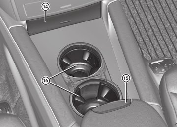
Cup holder in the rear seat armrest ! Do not sit on or support your body weight on the rear seat armrest when it is folded down, as you could otherwise damage it.
X Fold down the rear seat armrest.
Cup holder : is in the rear seat armrest.
Cup holder in the third row of seats The cup holders are located in the side trim on the left and right-hand sides.
Features
283
Glare from the side
: Cup holders
Sun visors Overview of sun visors G WARNING Do not use the vanity mirror while driving. Keep the vanity mirrors in the sun visors closed while the vehicle is in motion. Reflected glare can endanger you and others.
: Mirror light ; Bracket = Vanity mirror ? Retaining clip, e.g. for a car park ticket A Mirror cover
Vanity mirror in the sun visor Mirror light : only functions if the sun visor is clipped into retainer ; and mirror cover A has been folded up.
X Fold down sun visor :. X Pull sun visor : out of retainer =. X Swing sun visor : to the side. X Vehicles with a sliding sunroof: slide sun
visor : horizontally as desired.
X Vehicles with a sliding sunroof: fold
down additional sun visor ; to the windshield.
Roller sunblind, rear panorama roof The rear panorama roof roller sunblind protects the vehicle occupants in the third row of seats from direct sunlight. You can open/close the roller sunblind by hand. ! Always guide the roller sunblind by hand.
Do not let it snap back suddenly as this could damage the roller sunblind.
284 Features
X To close: pull out the roller sunblind using
handle = and attach arm ; to bracket :. The roller sunblind engages.
X To open: press release knob ? to release
the roller sunblind from bracket :. X Retract the roller sunblind by hand.
Ashtray Ashtray in the front-compartment center console i You can remove the ashtray insert and
use the resulting compartment for stowage.
! The stowage space under the ashtray is
not heat resistant. Before placing lit cigarettes in the ashtray, make sure that the ashtray is properly engaged. Otherwise, the stowage space could be damaged.
X To open: briefly press marking ?. Stowage compartment : opens.
X To remove the insert: lift insert =
up ; and out.
X To re-install the insert: press insert =
into the holder until it engages.
Ashtray in the rear-compartment center console ! Close the ashtray when it is not in use and before you fold the rear seats forward. You can otherwise damage the ashtray.
X To open: briefly press marking =.
Ashtray ; opens.
X To remove the insert: lift insert : up and
out.
X To install the insert: mount insert : from above into the holder and press down into the holder until it engages.
Cigarette lighter G WARNING When leaving the vehicle, always remove the SmartKey from the ignition lock. Always take the SmartKey with you and lock the vehicle. Do not leave children unattended in the vehicle, even if they are secured in a child restraint system, or with access to an unlocked vehicle. A child's unsupervised access to a vehicle could result in an accident and/or serious personal injury. The children could: Rinjure themselves on parts of the vehicle Rbe seriously or fatally injured through
excessive exposure to extreme heat or cold Rinjure themselves or cause an accident with
vehicle equipment that can be operated even if the SmartKey is removed from the ignition lock or removed from the vehicle, such as seat adjustment, steering wheel adjustment, or the memory function
If children open a door, they could injure other persons or get out of the vehicle and injure themselves or be injured by following traffic.
Do not expose the child restraint system to direct sunlight. The child restraint system's metal parts, for example, could become very hot, and the child could be burned on these parts. G WARNING Never touch the heating element or sides of the lighter; they are extremely hot. Hold the knob only. Make sure any children traveling with you do not injure themselves or start a fire with the hot cigarette lighter.
! The 12 V socket in the cigarette lighter
can be used for accessories (up to a maximum of 180 W) as long as they have the standard socket type for cigarette lighters. Note that the socket in the cigarette lighter can be damaged when connecting accessories, for example by frequent insertion and removal or by sockets that do not fit correctly. A damaged socket can cause the cigarette lighter to stop working.
! The cigarette lighter in the center console in the front compartment is not intended for operating the tire inflation compressor.
Features
285
X Turn the SmartKey to position 2 in the
ignition lock.
X To open: briefly press marking =. Stowage compartment : opens.
X Press in cigarette lighter ;.
Cigarette lighter ; will pop out automatically when the heating element is red-hot.
12 V sockets Points to observe before use ! The socket in the center console and the socket in the cargo compartment are not intended for operating the tire inflation compressor.
The sockets can be used for accessories, e. g. lamps or mobile phone chargers with a maximum current draw of 180 W (15 A). If you use the sockets for long periods when the engine is switched off, the battery may discharge. X Turn the SmartKey to position 2 in the
ignition lock.
i You can also use the power sockets when the SmartKey is in position 1 in the ignition lock. An emergency cut-out ensures that the on- board voltage does not drop too low. If the on-board voltage is too low, the power to the sockets is automatically cut. This ensures that there is sufficient power to start the engine.
286 Features
Socket in the front-passenger footwell
Socket in the rear-compartment center console
X Lift up the cover of socket :.
Socket in the front-compartment center console ! If accessories are connected, make sure that a maximum current draw of 15 A is not exceeded. Otherwise, you will overload the fuse.
! The socket is not suitable for operating
the tire inflation compressor.
X Lift up the cover of socket :.
Socket in the cargo compartment ! The socket is not suitable for operating
the tire inflation compressor.
X To open: briefly press marking =. Stowage compartment : opens.
X Remove cover from socket ;. i On vehicles with an ashtray and cigarette
lighter, you must remove the cigarette lighter (Y page 284) in order to use the socket.
X Lift up the cover of socket :.
115 V power socket G WARNING The 115V AC socket operates at high voltage. Use the 115V AC socket in the vehicle with the same caution and prudence that you exercise when using power outlets at home. Keep any fluids away from the 115V AC socket. Do not clean the socket with fluids or tapered objects. Keep the 115V AC socket cover in the closed position, when not in use. Otherwise, you could suffer an electric shock and be seriously or even fatally injured.
Features
287
G WARNING Any device that you connect must have a suitable plug and meet U.S. standards. Never pull at a cable to disconnect a plug from a 115 V AC power socket. Never use a damaged connection cable. The 115 V AC power socket must never be connected to another 115 V AC power source. Do not use a converter with an earthed plug for the 115 V AC power socket. This could cause serious injury to you and/or other people. G WARNING If the 115V AC socket is damaged or torn out of the trim, do not use or touch the 115V AC socket. Using a 115V AC socket that is damaged or torn out of the trim could cause serious personal injury to you and/or others.
X Open flap =. X Insert the plug of the electronic device into
115 V power socket :. Indicator lamp ; lights up. If indicator lamp ; does not light up, consult the section on malfunctions.
X To turn off: disconnect the plug from 115 V
power socket :. Ensure that you do not pull on the cord.
X Close flap =. Possible causes of malfunction: Rthe on-board power supply is not within a
permissible volt range.
Rthe temperature of the DC/AC converter is
temporarily too high.
Rsome small electronic devices have a constant nominal power of less than 150 W, but a very high inrush current. These devices will not work. If you connect such a device, 115 V power socket : will not supply it with power.
If indicator lamp ; still does not light up, contact a specialist workshop, e.g. an authorized Mercedes-Benz Center.
115 V socket : provides an alternating voltage of 115 V, so that small electronic devices can be connected. These devices, such as games consoles, chargers and laptops, together should not consume more than a maximum of 150 W. Requirements for operation of these devices: Rthe plug of the electronic device must be inserted fully into 115 V power socket :. Rthe maximum wattage of the device to be
connected must not exceed 150 W.
Rthe on-board power supply is within a
permissible volt range.
Rthe 12 V sockets in the rear and the cargo
compartment are operational (Y page 285).
mbrace Important safety notes ! A license agreement must exist in order to activate the mbrace service. Ensure that your system is activated and ready for use, and press the E MB Info call button to register. If any of the steps mentioned is not carried out, the system may not be activated. If you have questions about the activation, contact one of the following telephone assistance services: RUSA: Mercedes-Benz Customer
Assistance Center under 1-888-990-9007
RCanada: Customer Service at
1-888-923-8367
288 Features
Shortly after successfully registering with the mbrace service, a user ID and password will be sent to you by post. You can use this password to log in to the mbrace section under "Owners Online" at http:// www.mbusa.com32. The mbrace system is available if: Rit has been activated and is operational. Rthe corresponding mobile phone network
is available for transmitting data to the Customer Center.
Ra service subscription is available. Rthe starter battery is sufficiently charged. i Determining the location of the vehicle on a map is only possible if there is sufficient GPS reception and the vehicle position can be forwarded to the Customer Center.
The mbrace system The mbrace system provides different services, e.g.: Rautomatic and manual emergency call RRoadside Assistance call RMB Info call To adjust the volume during an mbrace call, proceed as follows: X Press the W or X button on the
multifunction steering wheel.
or X Use the volume controller of COMAND. You can find further information and a description of all available features under "Owners Online" at http:// www.mbusa.com33.
System self-test After you have switched on the ignition, the system carries out a self-diagnosis.
G WARNING A malfunction in the system has been detected if one of the following conditions occurs: Rthe indicator lamp in the SOS button does
not light up during the system self- diagnosis.
Rthe indicator lamp in the º Roadside
Assistance button does not light up during the system self-diagnosis.
RThe indicator lamp in the E information
button does not light up during self- diagnosis of the system.
Rthe indicator lamp in the SOS button,
º Roadside Assistance button or E information button continues to be lit red after the system self-diagnosis. RThe Tele Aid Inoperative or Tele Aid Not Activated message appears in the multifunction display after the system self- test.
If a malfunction is indicated as outlined above, the system may not operate as expected. In the event of an emergency, assistance must be summoned by other means. Have the system checked at the nearest authorized Mercedes-Benz Center or contact the following service hotlines: RUSA: Response Center under
888-990-9007
RCanada: Customer Service at
1-888-923-8367
Emergency call Important safety notes ! A license agreement must exist in order to activate the mbrace service. Ensure that your system is activated and ready for use, and press the E MB Info call button to register. If any of the steps mentioned is
32 USA only. 33 USA only.
not carried out, the system may not be activated. If you have questions about the activation, contact one of the following telephone assistance services: RUSA: Mercedes-Benz Customer
Assistance Center under 1-888-990-9007
RCanada: Customer Service at
1-888-923-8367
An emergency call is dialed automatically if an air bag or Emergency Tensioning Device is triggered. i An mbrace emergency call that has been
initiated automatically cannot be terminated by the customer.
An emergency call can also be initiated manually. As soon as the emergency call has been initiated, the indicator lamp in the SOS button flashes. The Connecting Call message appears on the multifunction display. The audio output is muted. Once a connection has been established, the Call Connected message appears in the multifunction display. All important information on the emergency is transmitted, for example: Rcurrent location of the vehicle (as
determined by the GPS system)
Rvehicle identification number Rinformation on the type of emergency Shortly after the emergency call has been initiated, a voice connection is automatically established between the Mercedes-Benz Customer Assistance Center and the vehicle occupants. If the vehicle occupants respond, the Mercedes-Benz Customer Assistance Center attempts to get more information on the emergency. i If no vehicle occupant answers, an ambulance is immediately sent to the vehicle.
Features
289
G WARNING If the indicator lamp in the SOS button is flashing continuously and no voice connection to the Mercedes-Benz Customer