- 2012 Mercedes-Benz G Class Owners Manuals
- Mercedes-Benz G Class Owners Manuals
- 2005 Mercedes-Benz G Class Owners Manuals
- Mercedes-Benz G Class Owners Manuals
- 2013 Mercedes-Benz G Class Owners Manuals
- Mercedes-Benz G Class Owners Manuals
- 2009 Mercedes-Benz G Class Owners Manuals
- Mercedes-Benz G Class Owners Manuals
- 2003 Mercedes-Benz G Class Owners Manuals
- Mercedes-Benz G Class Owners Manuals
- 2004 Mercedes-Benz G Class Owners Manuals
- Mercedes-Benz G Class Owners Manuals
- 2011 Mercedes-Benz G Class Owners Manuals
- Mercedes-Benz G Class Owners Manuals
- 2002 Mercedes-Benz G Class Owners Manuals
- Mercedes-Benz G Class Owners Manuals
- 2007 Mercedes-Benz G Class Owners Manuals
- Mercedes-Benz G Class Owners Manuals
- Download PDF Manual
-
앫 If the telephone is on:
The telephone will then search for a network. During this time the display is empty. As soon as the telephone has found a network, READY is indicated in the dis- play.
Answering a call When your telephone is ready to receive calls, you can answer a call at any time. In the display you will then see the message:
1 Signal strength This standby message indicates that your telephone is ready for use and you can op- erate it using the control system.
왘 Press button í.
You have answered the call. In the dis- play you see the length of the call.
Ending a call 왘 Press button ì.
You have ended the call. In the display you will again see the standby mes- sage.
You can use the functions in the TEL menu to operate your telephone, provided it is connected to a hands-free system and switched on. 왘 Switch on the telephone and COMAND. 왘 Press button ÿ or è on the
steering wheel repeatedly until you see the TEL menu in the display.
Which messages will appear in the display field depends on whether your telephone is switched on or off: 앫 If the telephone is off, the message in the multifunction display is: TEL OFF.
138
Dialing a number from the phone book If your telephone is ready to receive calls, you may select and dial a number from the phone book at any time. 왘 Press button ÿ or è repeatedly until you see the TEL menu in the dis- play.
왘 Press button j or k.
The control system reads the phone book which is stored in the telephone. This may take up to 30 seconds. In the display you will see the message PLEASE WAIT!. When the message PLEASE WAIT! dis- appears, the phone book has been loaded.
왘 Press button j or k repeatedly until the desired name appears in the display. The stored names are displayed in as- cending or descending alphabetical or- der.
If you press and hold j or k for longer than one second, the system scrolls rapidly through the list of names until you release the button again. Cancel the quick search mode by pressing ì.
왘 Press button í.
The system dials the selected phone number. 앫 If connection is successful, the
name of the party you called and the duration of the call will appear in the display.
앫 If no connection is made, the con- trol system stores the dialed num- ber in the redial memory.
Controls in detail Control system
Redialing The control system stores the most recent- ly dialed phone numbers. This eliminates the need to search through your entire phone book. 왘 Press button ÿ or è repeatedly until you see the TEL menu in the dis- play.
왘 Press button í.
In the display, you see the first number in the redial memory.
왘 Press button j or k repeatedly until the desired name appears in the display.
왘 Press button í.
The control system dials the selected phone number.
139
Controls in detail Automatic transmission 왔 Automatic transmission For more information on driving with an au- tomatic transmission, see the “Getting started” section (컄 page 43). Your vehicle’s transmission adapts its gear shifting process to your individual driving style by continually adjusting the shift points up or down. These shift point adjust- ments are performed based on current op- erating and driving conditions. If the operating conditions change, the au- tomatic transmission reacts by adjusting its gear shift program.
During the brief warm-up, transmission upshifting is delayed. This allows the catalytic converter to heat up more quickly to operating temperature.
140
The automatic transmission selects indi- vidual gears automatically, dependent upon 앫 the gear selector lever position D with
gear ranges 4, 3, 2, 1 (컄 page 142)
앫 transfer case position (HIGH or LOW) 앫 the position of the accelerator pedal
(컄 page 144)
앫 the vehicle speed The current gear selector lever position and the transfer case position (HIGH or LOW) appear in the multifunction display.
Warning!
It is dangerous to shift the gear selector lever out of P or N if the engine speed is higher than idle speed. If your foot is not firmly on the brake pedal, the vehicle could accelerate quickly forward or reverse. You could lose control of the vehicle and hit someone or something. Only shift into gear when the engine is idling normally and when your right foot is firmly on the brake pedal.
When the gear selector lever is in position D, you can influence transmission shifting by 앫 limiting the gear range 앫 changing gears manually
1 Transfer case display 2 Gear selector lever position/gear
range
Controls in detail Automatic transmission
To avoid overrevving the engine when the gear selector lever is moved to the D- direction, the transmission will not shift to a lower gear if the engine’s max. speed would be exceeded.
Canceling gear range limit 왘 Press and hold the gear selector lever in the D+ direction until D reappears in the multifunction display.
The transmission will shift from the current gear range directly to gear range D.
Upshifting 왘 Briefly press the gear selector lever to
the right in the D+ direction.
The transmission will shift from the current gear to the next higher gear as permitted by the shift program. This action simulta- neously extends the gear range of the transmission.
Shifting into optimal gear range 왘 Press and hold the gear selector lever
in the D- direction.
The transmission will automatically select the gear range suited for optimal accelera- tion and deceleration. This will involve shifting down one or more gears.
One-touch gearshifting
Even with an automatic transmission, you can change the gears manually when the gear selector lever is in position D.
Downshifting 왘 Briefly press the gear selector lever to
the left in the D– direction.
The transmission will shift from the current gear to the next lower gear. This action si- multaneously limits the gear range of the transmission (컄 page 142).
Warning!
On slippery road surfaces, never downshift in order to obtain braking action. This could result in drive wheel slip and reduced vehi- cle control. Your vehicle’s ABS will not pre- vent this type of loss of control.
141
Controls in detail Automatic transmission
Gear ranges
With the gear selector lever in position D, you can limit the transmission’s gear range by pressing the gear selector lever to the left (D-), and reverse the gear range limit by pressing the gear selector lever to the right (D+). The selected gear range will appear in the multifunction display. If you press on the accelerator when the engine has reached its rpm limit, the transmission will upshift beyond any gear range limit selected.
If the transfer case is in off-road driving position LOW, the automatic transmis- sion will not shift up automatically, even when the engine has reached the speed limit for that gear. There is a risk of damaging the engine. It is very important to make sure the permissible engine speed is not ex- ceeded.
142
Effect
é The transmission shifts through fourth gear only. è The transmission shifts through third gear only. With this selection you can use the braking effect of the engine.
ç The transmission shifts
through second gear only. Allows the use of engine’s braking power when driving 앫 on steep downgrades 앫 in mountainous regions 앫 under extreme operating
conditions
æ The transmission operates in
first gear only. For maximum use of engine’s braking effect on very steep or lengthy downgrades.
Gear selector lever position
Effect
ì Park position
Gear selector lever position when the vehicle is parked. Place gear selector lever in position P only when vehicle is stopped. The park position is not intended to serve as a brake when the vehicle is parked. Rather, the driver should always set the parking brake in addition to placing the gear selector lever in position P to secure the vehicle.
Effect The SmartKey can only be removed from the starter switch with the gear selector lever in position P. With the SmartKey removed, the gear selector lever is locked in position P. If the vehicle’s electrical system is malfunctioning, the gear selector lever could remain locked in position P (컄 page 290). í Reverse gear
Place gear selector lever in position R only when vehicle is stopped.
Effect ë Neutral
No power is transmitted from the engine to the drive axle. When the brakes are released, the vehicle can be moved freely (pushed or towed). Do not engage N while driving except: 앫 to coast when vehicle is in danger of skidding (e.g. on icy roads) when the ESP is deactivated or malfunction- ing
앫 when you have to shift the
transfer case
ê Drive
The transmission shifts automatically. All five forward gears are available.
Controls in detail Automatic transmission
Coasting the vehicle, or driving for any other reason with gear selector lever in N can result in transmission damage that is not covered by the Mercedes-Benz Limited Warranty.
Warning!
Getting out of your vehicle with the gear se- lector lever not fully engaged in position P is dangerous. Also, position P alone is not in- tended to or capable of preventing your ve- hicle from moving, possibly hitting people or objects.
Always set the parking brake in addition to shifting to position P (컄 page 51). When parked on an incline, turn the front wheels towards the road curb.
Do not park this vehicle in areas where com- bustible materials such as grass, hay or leaves can come into contact with the hot exhaust system, as these materials could be ignited and cause a vehicle fire.
143
Controls in detail Automatic transmission
Warning!
Accelerator position
When leaving the vehicle, always remove the SmartKey from the starter switch, and lock the vehicle. Do not leave children unattend- ed in the vehicle, or with access to an un- locked vehicle. Children could move the gear selector lever from position P, which could result in an accident and/or serious personal injury.
Your driving style influences the transmis- sion’s shifting behavior: Less throttle More throttle
Earlier upshifting Later upshifting
Kickdown Use kickdown when you want maximum acceleration. 왘 Press the accelerator past the point of
resistance. The transmission shifts into a lower gear.
왘 Ease on the accelerator when you have
reached the desired speed. The transmission shifts up again.
Emergency operation (Limp Home Mode)
If vehicle acceleration worsens or the transmission no longer shifts, the trans- mission is most likely operating in limp home (emergency operation) mode. In this mode, only 2nd gear and reverse gear can be activated. 왘 Stop the vehicle. 왘 Move gear selector lever to P. 왘 Turn off the engine. 왘 Wait at least ten seconds before re-
starting.
왘 Restart the engine. 왘 Move gear selector lever to position D
(for second gear) or R.
왘 Have the transmission checked at an authorized Mercedes-Benz Light Truck Center as soon as possible.
144
왔 Transfer case For more information on off-road driving, see “Off-road driving” (컄 page 213).
Gear range
Neutral No power is transmitted from the engine to the drive axle.
Controls in detail Transfer case
Switching transfer case The switch is located in the center console. 1 Transfer case indicator
2 Gear range indicator Transfer case indicator 1 in the multi- function display shows the gear position of the transfer case.
HIGH Road position LOW Off-road position This position is intended for driving off-road and step gradi- ents. The transmission will not up- shift automatically to the next higher gear range when driving at the rpm limit. The transfer case supports the engine’s driving force (approx. 1/2 speed). Output is there- fore increased.
145
Controls in detail Transfer case
Switching from HIGH to LOW
Switching from LOW to HIGH
The shift procedure can only be per- formed when: 앫 The engine is running. 앫 The gear selector lever for the auto- matic transmission is in position N.
앫 The vehicle is not at standstill. 앫 The vehicle speed does not exceed
25 mph (40 km/h).
The shift procedure can only be per- formed when: 앫 The engine is running. 앫 The gear selector lever for the auto- matic transmission is in position N.
앫 The vehicle is not at standstill. 앫 The vehicle speed does not exceed
40 mph (70 km/h).
왘 Press upper half (“LOW”) of the trans-
왘 Press lower half (“HIGH”) of the trans-
fer case switch. Once the shift is complete, gear position L is displayed in the transfer case indicator. If the shift procedure does not take place press upper half (“LOW”) of the transfer case switch again.
fer case switch. Once the shift is complete, gear position H is displayed in the transfer case indicator. If the shift procedure does not take place press lower half (“HIGH”) of the transfer case switch again.
Messages in the multifunction display If a shift was not completed and the multi- function display shows one of the following messages: 앫 TC SHIFT CONDITIONS NOT FULFILLED The shift did not take place. At least one shift condition was not met.
왘 Repeat the shift procedure. 앫 TC IN NEUTRAL
The shift did not take place. The trans- fer case is in neutral. The gear position N is displayed in the transfer case indicator 1.
왘 Repeat the shift procedure.
Warning!
If TC is in neutral, transmission position P will not hold vehicle. The parking brake must be applied to hold vehicle in place.
왘 Put gear selector in D.
왘 Put gear selector in D.
146
앫 TC SHIFT – CANCELLED
The shift did not take place. 왘 Repeat the shift procedure. 앫 TRANSFER CASE – VISIT WORKSHOP!
There may be a malfunction in the sys- tem.
왘 Repeat the shift procedure. 왘 If the shift procedure still does not take place, have the vehicle checked at your authorized Mercedes-Benz Light Truck Center as soon as possible.
If the SmartKey is in starter switch position 0 or 1, an alarm will sound if the transfer case is in position N and the driver’s door is opened. Engage transfer case to gear position HIGH or LOW.
For more information, see “Practical hints” section (컄 page 281).
Controls in detail Transfer case
147
Controls in detail Differential locks 왔 Differential locks For more information on off-road driving, see “Off-road driving” (컄 page 213). Differential locks improve the vehicle’s tractive power off-road. Switch on differen- tial locks: 앫 for off-road driving 앫 to turn the ABS off during off-road driv-
ing
앫 for driving through water 앫 when driving on deep snow and icy or
fouled surfaces
Do not engage the front axle differen- tial lock when driving around tight cor- ners. This restricts steering ability.
When driving off-road, apply only mod- erate pressure to the accelerator pedal if the differential locks are switched on. When running on a (single-axle) dyna- mometer – no matter how briefly – you must: 앫 raise the non-driven axle or 앫 disconnect its drive shaft and 앫 engage the transfer differential lock Otherwise the transfer case can be damaged, which is not covered by the Mercedes-Benz Limited Warranty.
Warning!
Never drive on pavement with differential locks engaged.
Steering control will be strongly affected with the differential locks activated.
The ABS, BAS and ESP are switched off au- tomatically when the transfer case differen- tial lock is activated.
148
Controls in detail Differential locks
A few words about differentials and differential locks
When a vehicle negotiates a turn, wheels on the outside of the curve must travel far- ther and rotate faster than the inside wheels. The differential, the operation of a set of gears that allows the powered wheels in a vehicle to turn at different speeds, makes this essential function pos- sible. The drawback is that the differential also sends most of the engine’s power to the wheel with the least load or strain on it. For example, if one of a vehicle’s powered wheels sits on a patch of snow and spins because there is no traction, all of the en- gine’s power will go to that wheel because the power will take the path of least resis- tance. Meanwhile, the opposite wheel, sit- ting on dry pavement where it could get enough grip to start the vehicle moving, sits idle because it receives no power.
The Electronic Traction System (ETS) ad- dresses this problem and provides for good control and steering ability by auto- matically slowing the slipping wheel and thus increasing the power to the other non-slipping drive wheels to get the vehicle moving. The ESP and ETS in this vehicle feature such intelligent limited-slip differ- ential technology, ideally suited for on-road and light off-road driving. Transfer case position LOW (컄 page 145) also en- hances off-road driving capabilities (컄 page 213). More extreme off-road conditions may call for another solution, engaging a differen- tial lock or preventing the differential from operating altogether. As part of its stan- dard equipment, this vehicle comes with three differential locks: front, transfer case (center) and rear. Each can be engaged simply by pushing dashboard-mounted buttons in sequential order (center, rear, front) (컄 page 150). When the transfer case (center) differential is locked, half of the engine’s power is automatically distrib- uted to the front wheels and half to the
rear wheels. When the rear differential is locked, power going to the rear wheels is equally distributed, so that both rear wheels turn at the same speed and torque. When the front differential is locked, all four wheels now turn with equal power and torque. Please be aware that engaging the differential locks will significantly reduce the steering ability of the vehicle. For your safety and the safety of others and to prevent damage to the vehicle, the differential locks must not be engaged when driving on paved roads. It is impor- tant to understand that during on-road/paved driving, differentials are absolutely necessary for providing the es- sential control and steering ability of the vehicle. The differential locks, therefore, must not be engaged when driving on paved roads and should only be used to the extent necessary to negotiate off-road conditions which cannot be handled by the systems (automatic 4-ETS, the ESP, manu- al switch position “LOW” of transfer case) this vehicle comes equipped with.
149
Controls in detail Differential locks
Switching differential locks on and off
Switching differential locks on
The switch is located in the center console.
1 Transfer case (center) differential lock 2 Rear axle differential lock 3 Front differential lock 4 Engagement indicator lamps (yellow) 5 Function indicator lamps (red)
The differential locks can only be switched on in the sequence 1, 2, 3.
150
To avoid damage to the transfer case and differential locks: 앫 Engage differential locks only at low
speed (walking speed, not more than 5 mph).
앫 Do not engage differential locks if the driving wheels are spinning due to lack of traction.
앫 Do not engage on paved roads.
Transfer case differential lock 왘 Press switch 1.
The yellow engagement indicator lamp 4 for the transfer case differen- tial lock comes on. The ESP warning lamp v comes on. When the differential lock engagement operation has been completed, the red function indicator lamp 5 comes on.
The message ABS NOT AVAILABLE – DIFFERENTIAL LOCKED appears in the multifunction display. The ESP warning lamp v and the ABS - warning lamp in the instru- ment cluster come on. Once the transfer case differential lock is switched on, you can now, if needed, 앫 switch on rear axle differential
lock 2 or
앫 switch on rear axle differential lock
and front differential lock 2 and 3.
Rear axle differential lock 왘 Press switch 2.
The yellow engagement indicator lamp 4 comes on first, followed by the red function indicator lamp 5. The rear axle differential lock is switched on.
Front differential lock 왘 Press switch 3.
The yellow engagement indicator lamp 4 comes on first, followed by the red function indicator lamp 5. The front differential lock is switched on.
Controls in detail Differential locks
Switching differential locks off There are two different methods to disen- gage differential locks: 앫 You can switch the differential locks off
in reverse order (3, 2, 1).
앫 To switch off all differential locks at the
same time: 왘 Press switch 1.
The yellow engagement indicator lamps 4 go out first. The red func- tion indicator lamps 5 go out when the switching process has been carried out in the differential.
To activate the ESP, BAS and ABS systems, drive again for three seconds using a con- stant driving style. All messages in the multifunction display disappear. The ESP warning lamp v and the ABS - warning lamp in the in- strument cluster go out.
If the function lamps do not go out when the differential locks are disen- gaged, bring vehicle to a stop and then continue driving. Changing the vehicle load can help to disengage locks.
Warning!
Always remember to disengage the differen- tial locks when returning to drive on paved roads, see “A few words about differentials and differential locks” (컄 page 149).
151
Controls in detail Good visibility 왔 Good visibility For information on windshield wipers, see “Windshield wipers” (컄 page 47) and for setting the exterior rear view mirrors, see “Exterior rear view mirror” (컄 page 38).
Rear view mirror
Automatic antiglare rear view mirrors The reflection brightness of the exterior rear view mirrors and the interior rear view mirror will respond automatically to glare when 앫 the ignition is switched on, and 앫 incoming light from headlamps falls on the sensor in the interior rear view mir- ror
The interior rear view mirror will not react if 앫 reverse gear is engaged 앫 the interior lighting is turned on
152
Warning!
Warning!
The automatic antiglare function does not react if incoming light is not aimed directly at sensors in the interior rear view mirror.
In the case of an accident, liquid electrolyte may escape from the mirror housing if the mirror glass breaks.
Electrolyte has an irritating effect. Do not al- low the liquid to come into contact with eyes, skin, clothing, or the respiratory sys- tem. In case it does, immediately flush af- fected area with water, and seek medical help if necessary.
The interior rear view mirror and the exterior rear view mirrors do not react, for example, if the cargo compartment is fully loaded.
Glare can endanger you and others.
Warning!
Exercise care when using the passen- ger-side exterior rear view mirror. The mirror surface is convex (outwardly curved surface for a wider field of view). Objects in mirror are closer than they appear. Check your in- side rear view mirror or glance over your shoulder before changing lanes.
Activating exterior rear view mirror parking position Follow these steps to activate the mirror parking position so that the passen- ger-side exterior rear view mirror will be turned downward to the stored position. 왘 Make sure you stored a parking posi- tion for the passenger-side exterior rear view mirror (컄 page 103).
왘 Make sure the MIRROR SETTING WHEN PARKING function, found under the CON- VENIENCE submenu in the control sys- tem, is switched to ON (컄 page 135).
왘 Switch on ignition. 왘 Press button 2 for the passenger-side
exterior rear view mirror.
왘 Place the gear selector lever in reverse
gear R. The passenger-side exterior rear view mirror will be turned downward to the stored position.
Controls in detail Good visibility
Headlamp cleaning system
The switch is located to the left of the steering column.
1 Driver’s side exterior rear view mirror
button
2 Passenger-side exterior rear view mir-
ror button
The exterior rear view mirror returns to its previously stored driving position: 앫 10 seconds after you put the gear se-
lector lever out of position R
앫 immediately once you exceed a vehicle
speed of approx. 6 mph (10 km/h)
앫 immediately when you press button 1 for driver’s side exterior rear view mir- ror
1 Headlamp washer switch 왘 Switch on ignition. 왘 Press switch 1.
The headlamps will be cleaned with a high-pressure water jet.
153
Controls in detail Good visibility
Sun visors
The sun visors protect you from sun glare while driving.
Warning!
Do not use the vanity mirror while driving.
Keep the mirrors in the sun visors closed while vehicle is in motion. Reflected glare can endanger you and others.
154
1 Sun visor 2 Mounting 왘 Swing sun visors 1 down to protect
against sun glare.
왘 If sunlight enters through a side win- dow, disengage visor 1 from inner mounting 2 and pivot it to the side.
3 Mirror cover 4 Mirror lamp 왘 Make sure the ignition is switched on
and that the sun visor is engaged in mounting 2.
왘 Open mirror cover 3.
Mirror lamps 4 switch on.
Rear window defroster
Turn the SmartKey in starter switch to position 2.
Activating 왘 Press button F in the control panel
of the climate control. The indicator lamp in the button comes on.
Deactivating 왘 Press button F in the control panel
of the climate control. The indicator lamp in the button goes out.
Heavy accumulation of snow and ice should be removed before activating the defroster. The defroster is automatically turned off after approximately 6-17 minutes of operation depending on the outside temperature and vehicle speed. If several power consumers are turned on simultaneously, or the battery is only partially charged, it is possible that the defroster will automatically turn it- self off. When this happens, the indicator lamp inside the switch starts blinking. As soon as the battery has sufficient voltage, the defroster turns itself back on.
Controls in detail Good visibility
The rear window defroster uses a large amount of power. To keep the battery drain to a minimum, turn off the de- froster as soon as the rear window is clear.
155
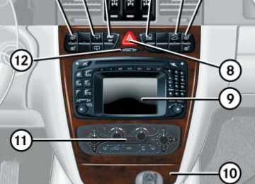
Controls in detail Climate control 왔 Climate control
156
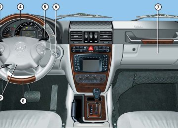
1 Windshield defroster air vents 2 Center air vent, adjustable 3 Thumbwheel for center air vent 4 Side air vent, adjustable 5 Side defroster air vent, fixed 6 Thumbwheel for side air vent 7 Footwell air vents 8 Climate control panel
For draft-free ventilation, move the slid- ers for the center air vents to the mid- dle position.
Climate control panel
Controls in detail Climate control
1 Air volume 2 Temperature control, left 3 Temperature control, right 4 Air distribution control 5 Rear window defroster (컄 page 155) 6 AC cooling on /off (ACOFF)
Residual engine heat utilization (REST)
7 Air distribution and air volume (auto-
matic mode)
8 Air recirculation 9 Defrosting
157
Controls in detail Climate control
The climate control is operational whenev- er the engine is running. You can operate the climate control system in either the au- tomatic or manual mode. The system cools or heats the interior depending on the se- lected interior temperature and the cur- rent outside temperature.
Nearly all dust particles, pollutants and odors are filtered out before outside air en- ters the passenger compartment through the air distribution system. The air conditioning will not engage (no cooling) if the ACOFF mode is selected (컄 page 162).
Warning!
Warning!
Follow the recommended settings for heat- ing and cooling given on the following pag- es. Otherwise the windows could fog up, impairing visibility and endangering you and others.
When operating the automatic climate con- trol, the air that enters the passenger com- partment through the air vents in the footwell can be very hot or very cold (de- pending on the set temperature). This may cause burns or frostbite on unprotected skin in the immediate area of the air vents. Al- ways keep sufficient distance between un- protected parts of the body and the footwell air vents. If necessary, change the air flow using the air distribution controls to direct the air away from the footwell air vents (컄 page 159).
158
If the vehicle interior is hot, ventilate the interior before driving off. Keep the air intake grille in front of the windshield free of snow and debris.
Setting the temperature
Use temperature controls 2 and 3 to separately adjust the air temperature on each side of the passenger compartment. You should raise or lower the temperature setting in small increments, preferably starting at 72°F (22°C).
When operating the climate control system in automatic mode, you will only rarely need to adjust the tempera- ture, air volume and air distribution.
Controls in detail Climate control
Adjusting manually 왘 Press the U button.
The indicator lamp on the button goes out.
왘 Select any of the six air volume speeds
and the air distribution.
Increasing 왘 Turn the temperature control a few de-
grees to the right. The climate control system will corre- spondingly adjust the interior air tem- perature.
Decreasing 왘 Turn the temperature control a few de-
grees to the left. The climate control system will corre- spondingly adjust the interior air tem- perature.
Adjusting air distribution and volume
Use air distribution control 4 (컄 page 157) to adjust the air distribution. The following symbols are found on the controls:
Symbol Function a Directs air through the center, side and rear passenger com- partment air vents
Z Directs air to the windows X Directs air into the entire vehi-
cle interior
Y Directs air to the footwells
159
Controls in detail Climate control
Adjusting automatically 왘 Press the U button.
The indicator lamp on the button comes on. Air distribution and volume are adjusted automatically.
Windshield fogged on the outside 왘 Switch the windshield wipers on. 왘 Switch to manual mode. 왘 Turn the air distribution control
to a or Y.
160
Defrosting
Air recirculation
Activating 왘 Press button P.
The indicator lamp in the button illumi- nates. The climate control automatically switches to the following functions: 앫 maximum blower and heat output 앫 air distribution to the windshield
and the side windows
앫 rear ventilation is turned off
Switch to air recirculation mode to prevent unpleasant odors from entering the vehicle from the outside. This setting cuts off the intake of outside air and recirculates the air in the passenger compartment.
Warning!
When the outside temperature is below 41°F (5°C), only switch to air recirculation mode for short periods to prevent window fogging.
Deactivating 왘 Press the P button.
Activating 왘 Press button O briefly.
The indicator lamp in the button goes out. Defrosting is turned off.
The indicator lamp in the button illumi- nates.
i The air recirculation mode is activated automatically at high outside tempera- tures. If you have turned off the air condition- er or the outside temperature is below 41°F (5°C), the air recirculation mode will not switch on automatically.
Deactivating 왘 Press button O briefly.
The indicator lamp in the button goes out.
The air recirculation mode is deactivated automatically: 앫 after 30 minutes if the outside temper-
ature is above about 41°F (5°C)
앫 after 5 minutes if the outside tempera-
ture is below about 41°F (5°C)
앫 after 5 minutes if economy mode
ACOFF is selected
Residual engine heat utilization
With the engine switched off, it is possible to continue to heat or ventilate the interior for a short while, depending on the temper- ature setting of the climate control. Air vol- ume and distribution are controlled automatically.
Activating 왘 Turn the SmartKey in starter switch to
position 1 or 0 or remove it from the starter switch.
왘 Press button °.
The indicator lamp in the button comes on. Set the left and right temperature to your personal requirements.
Controls in detail Climate control
Deactivating 왘 Press button ° again to switch off. The indicator lamp in the button goes out.
The residual heat is automatically turned off: 앫 when the SmartKey in starter switch is
turned to position 2
앫 after about 30 minutes 앫 if the battery voltage drops
161
Controls in detail Climate control
Deactivating the climate control system
Deactivating 왘 Set the air volume control switch to
position 0.
Reactivating 왘 Set the air volume control switch to any
speed.
162
Air conditioning
The air conditioning is operational while the engine is running and cools the interior air to the temperature set by the operator.
Condensation may drip out from under- neath the vehicle. This is normal and not an indication of a malfunction.
Deactivating It is possible to deactivate the air condi- tioning (cooling) function of the climate control system. The air in the vehicle will then no longer be cooled or dehumidified. 왘 Press button °.
The indicator lamp on the button ° comes on.
Activating Moist air can fog up the windows. You can dehumidify the air with the air conditioner. 왘 Press button ° again.
The indicator lamp on the button ° goes out.
The air conditioner uses the refrigerant R134a. This refrigerant is free of CFCs which are harmful to the ozone layer.
If the ° button on the climate con- trol panel starts to blink, this indicates that the air conditioner is losing refrig- erant. The compressor has turned itself off. The air conditioner cannot be turned on again. 앫 Have the air conditioner checked at
the nearest authorized Mercedes-Benz Light Truck Center.
Rear passenger compartment adjustable air vents
1 Air volume control for center air vents 2 Left center air vent, adjustable 3 Right center air vent, adjustable
Controls in detail Climate control
163
Controls in detail Power windows 왔 Power windows Opening and closing the windows
The side windows can be opened and closed electrically. The switches for all the side windows are on the driver’s door. The switches for the respective windows are on the front passenger and the rear doors.
1 Switch for rear door window override
(컄 page 71)
2 Left front window 3 Right front window 4 Right rear window 5 Left rear window
164
Warning!
Opening the windows 왘 Press switch 2 to 5 to the resistance
When closing the windows, make sure there is no danger of anyone being harmed by the closing procedure.
The closing procedure can be immediately halted by releasing the switch or by releas- ing button ‹ on the SmartKey.
When leaving the vehicle, always remove the SmartKey from starter switch, and lock your vehicle. Do not leave children unattended in the vehicle, or with access to an unlocked vehicle. Unsupervised use of vehicle equip- ment can cause an accident and/or serious personal injury.
왘 Turn SmartKey in the starter switch to
position 1 or 2.
point. The corresponding window will move downwards until you release the switch.
Closing the windows 왘 Pull on switch 2 to 5.
The corresponding window will move upwards until you release the switch.
Fully opening windows (Express-open) 왘 Press switch 2 to 5 past the resis-
tance point and release. The corresponding window opens com- pletely.
Stopping windows 왘 Press or pull respective switch again.
Controls in detail Power windows
Opening (Summer opening feature) 왘 Press and hold button Œ after un-
Closing (Convenience feature) 왘 Press and hold button ‹ after lock-
locking the vehicle. The windows and sliding/pop-up roof begin to open after approximately one second.
ing the vehicle. The windows and sliding/pop-up roof begin to close after approximately one second.
왘 Release transmit button to interrupt
왘 Release transmit button to interrupt
procedure.
procedure.
Make sure all side windows and the slid- ing/pop-up roof are properly closed before leaving the vehicle.
Opening and closing windows with the SmartKey The sliding/pop-up roof (컄 page 166) will also be opened or closed when the power windows are operated with the SmartKey.
Warning!
Never operate the windows or slid- ing/pop-up roof if there is the possibility of anyone being harmed by the opening or closing procedure.
In case the procedure causes potential dan- ger, the procedure can be immediately halt- ed by releasing the button on the SmartKey. To reverse direction of movement, press Œ for opening or ‹ for closing.
왘 Aim transmitter eye at the driver’s door
handle.
165
Controls in detail Sliding/pop-up roof 왔 Sliding/pop-up roof Opening and closing the sliding/pop-up roof
1 Push up to raise roof at rear 2 Pull down to lower roof at rear 3 Push forward to slide roof closed 4 Push back to slide roof open With the roof closed or tilted open, a screen can be slid into the roof opening to guard against sun rays. When sliding the roof open, the screen will also retract.
166
Warning!
When closing the sliding/pop-up roof, make sure there is no danger of anyone being harmed by the closing procedure.
The closing procedure of the sliding/pop-up roof can be immediately halted by releasing the switch.
When leaving the vehicle, always remove the SmartKey from starter switch, and lock your vehicle. Do not leave children unattended in the vehicle, or with access to an unlocked vehicle. Unsupervised use of vehicle equip- ment can cause an accident and/or serious personal injury.
To avoid damaging the seals, do not transport any objects with sharp edges which can stick out of the sliding/pop-up roof. Do not open the sliding/pop-up roof if there is snow or ice on the roof, as this could result in malfunctions. The sliding/pop-up roof can be opened or closed manually should an electrical malfunction occur (컄 page 292).
You can also open or close the sliding/pop-up roof using the SmartKey (summer opening/conve- nience feature) (컄 page 167).
왘 Turn the SmartKey in the starter switch
to position 1 or 2.
Opening and closing the sliding/pop-up roof 왘 To open, close, raise or lower the slid- ing/pop-up roof, move the switch to the resistance point in the required direction 1 to 4. Release the switch when the roof has reached the required position.
Fully opening (Express-open) 왘 To open the sliding/pop-up roof, move the switch past the resistance point in direction 4 and release. The sliding/pop up roof opens com- pletely.
Stopping the sliding/pop-up roof 왘 Move the switch in any direction.
If the movement of the sliding/pop-up roof is blocked during the closing pro- cedure, the roof will stop and reopen slightly.
Controls in detail Sliding/pop-up roof
Opening and closing the sliding/pop-up roof with the SmartKey The power windows (컄 page 164) will also be opened or closed when you operate the sliding/pop-up roof with the SmartKey.
Warning!
Never operate the windows or slid- ing/pop-up roof if there is the possibility of anyone being harmed by the opening or closing procedure.
In case the procedure causes potential dan- ger, the procedure can be immediately halt- ed by releasing the button on the SmartKey. To reverse direction of movement, press Œ for opening or ‹ for closing.
왘 Aim transmitter eye at the driver’s door
handle.
167
Controls in detail Sliding/pop-up roof
Opening (Summer opening feature) 왘 Press and hold button Œ after un-
Closing (Convenience feature) 왘 Press and hold button ‹ after lock-
locking the vehicle. The windows and sliding/pop-up roof begin to open after approximately one second.
ing the vehicle. The windows and sliding/pop-up roof begin to close after approximately one second.
왘 Release transmit button to interrupt
왘 Release transmit button to interrupt
procedure.
procedure.
Make sure all side windows and the slid- ing/pop-up roof are properly closed before leaving the vehicle.
168
왔 Driving systems The driving systems of your vehicle are de- scribed on the following pages: 앫 Cruise control, with which the vehicle
can maintain a preset speed.
앫 Rear Parking Assist*, with which you
can assist your parking maneuvers.
The BAS, ABS, ESP, 4-ETS and EBB driving systems are described in the “Safety and Security” section (컄 page 74).
Cruise control
Cruise control automatically maintains the speed you set for your vehicle. Use of cruise control is recommended for driving at a constant speed for extended periods of time. You can set or resume cruise control at any speed over 20 mph (30 km/h). The cruise control function is operated by means of the cruise control lever. The cruise control lever is the uppermost lever found on the left-hand side of the steering column (컄 page 23).
The cruise control should not be acti- vated during-off road driving.
Controls in detail Driving systems
Warning!
Cruise control is a convenience system de- signed to assist the driver during vehicle op- eration. The driver is and must always remain responsible for the vehicle speed and for safe brake operation.
Only use cruise control if the road, traffic and weather conditions make it advisable to travel at a steady speed. 앫 The use of cruise control can be danger- ous on winding roads or in heavy traffic because conditions do not allow safe driving at a steady speed.
앫 The use of cruise control can be danger- ous on slippery roads. Rapid changes in tire traction can result in wheel spin and loss of control.
앫 Deactivate cruise control when driving
in fog.
The “Resume” function should only be oper- ated if the driver is fully aware of the previ- ously set speed and wishes to resume this particular preset speed.
169
! Moving gear selector lever to position N while driving also cancels cruise control. However, the gear se- lector lever should not be moved to position N while driving except to coast when the vehicle is in danger of skid- ding (e.g. on icy roads).
The last stored speed is canceled when you turn off the engine.
On uphill or downhill grades, cruise control may not be able to maintain the set speed. Once the grade eases, the set speed will be resumed.
Canceling cruise control There are several ways to cancel cruise control: 왘 Step on the brake pedal. or 왘 Briefly push the cruise control lever to
position 3. Cruise control will be canceled. The last speed set will be stored for later use.
Controls in detail Driving systems
1 Set current or higher speed 2 Set current or lower speed 3 Cancel cruise control 4 Resume at last set speed
Setting current speed 왘 Accelerate or decelerate to the desired
speed.
왘 Briefly lift 1 or depress 2 the cruise
control lever. The current speed is set.
왘 Remove your foot from the accelerator
pedal. Cruise control is activated.
170
Controls in detail Driving systems
When you use the cruise control lever to decelerate, the transmission will au- tomatically downshift if the engine’s braking power does not brake the vehi- cle sufficiently.
Fine adjustment in 1 mph (Canada: 1 km/h) increments
Faster 왘 Briefly tip the cruise control lever in the
direction of arrow 1.
Slower 왘 Briefly tip the cruise control lever in the
direction of arrow 2.
Setting to last stored speed (“Resume” function)
Warning!
The speed stored in memory should only be set again if prevailing road conditions per- mit. Possible acceleration or deceleration differences arising from returning to preset speed could endanger yourself and others.
왘 Briefly push the cruise control lever to
position 4. Cruise control will resume the last set speed.
왘 Remove your foot from the accelerator
pedal.
Setting a higher speed 왘 Lift the cruise control lever to
position 1 and hold it up until the de- sired speed is reached.
왘 Release the cruise control lever.
The new speed is set. Depressing the accelerator pedal does not deactivate the cruise control. After brief acceleration (e.g. for passing), the cruise control will resume the last speed set.
Setting a lower speed 왘 Depress the cruise control lever to
position 2 and hold it down until the desired speed is reached.
왘 Release the cruise control lever.
The new speed is set.
171
Controls in detail Driving systems
Rear Parking Assist*
Warning!
Rear Parking Assist (rear Parktronic) is a supplemental system. It is not intended to, nor does it replace, the need for extreme care. The responsibility during parking and other critical maneuvers always rests with the driver.
Special attention must be paid to objects with smooth surfaces or low silhouettes (e.g. trailer couplings, painted posts, or street curbs). Such objects may not be de- tected by the system and can damage the vehicle.
The operational function of the Rear Parking Assist can be affected by dirty sensors, es- pecially at times of snow and ice. See “Cleaning the Rear Parking Assist sensors” (컄 page 247).
172
The Rear Parking Assist system monitors the rear area of your vehicle by means of four sensors in the rear bumper.
1 Sensors
Interference caused by other ultrasonic sig- nals (e.g. working jackhammers or the air brakes of trucks) can cause the system to send erratic indications, and should be tak- en into consideration.
Warning!
Make sure no persons or animals are in the area in which you are maneuvering. You could otherwise injure them.
The Rear Parking Assist system is an elec- tronic aid designed to assist the driver dur- ing parking maneuvers. It visually and audibly indicates the relative distance be- tween the rear of the vehicle and an obsta- cle. The Rear Parking Assist system is auto- matically activated when you switch on the ignition and shift the gear selector lever to position R.
Controls in detail Driving systems
Minimum distance The minimum distance between the sen- sors and an obstacle is approximately 20 in (50 cm). If you encounter an obstacle in this range, all the warning lamps come on and you hear a warning signal. If the ob- stacle is closer than the minimum dis- tance, the actual distance may no longer be indicated by the system.
Range of the sensors To function properly, the sensors must be free of dirt, ice, snow and slush. Clean the sensors regularly, being careful not to scratch or damage them.
Center Corners
approx. 59.1 in (150 cm) approx. 40 in (100 cm)
During parking maneuvers, pay special attention to objects located above or below the height of the sensors (e.g. planters or trailer hitches). The Rear Parking Assist system will not detect such objects at close range and dam- age to your vehicle or the object may result. Ultrasonic signals from outside sourc- es (e.g. truck air brakes or jackham- mers) may impair the operation of the Rear Parking Assist system.
173
Controls in detail Driving systems
Warning indicator Visual signals indicate to the driver the rel- ative distance between the sensors and an obstacle. The warning indicator is located next to the tailgate.
Warning indicator As your vehicle approaches an object, one or more segments will come on, depending on the distance. When the sixth segment lights, you have reached the minimum dis- tance.
174
An intermittent acoustic warning will sound when the first yellow segment comes on. This signal quickens with each additional segment lit. When all segments illuminate, the acoustic warning becomes a constant signal. The signal is canceled when the gear selector lever is placed in position D or P.
Rear Parking Assist malfunction There is a malfunction in the Rear Parking Assist system if: 앫 a low warning tone sounds while the
vehicle is reversing The Rear Parking Assist sensors are dirty or malfunctioning. 왘 Clean the Rear Parking Assist sys-
tem sensors (컄 page 247).
왘 Switch on the ignition again.
앫 no segments come on and no warning
sounds The Rear Parking Assist is malfunction- ing. 왘 Have the Rear Parking Assist sys-
tem checked by an authorized Mercedes-Benz Light Truck Center as soon as possible.
Malfunction may also be caused by inter- ference from other radio or ultrasonic sig- nals. 왘 Check the Rear Parking Assist opera- tion at another location to rule out in- terference from outside radio or ultrasonic signals.
Controls in detail Loading
Rolling up the cover 왘 Grip the cover strap and remove it from
the mountings on both sides.
왘 Guide it slowly back into place.
Cargo compartment cover
왔 Loading Roof rack
This vehicle is not intended to carry items on its roof. Thus roof rails and any roof-mounted devices must not be used.
Warning!
Do not load items on the roof. It may cause instability during some maneuvers which could result in an accident.
1 Rear seat bench cover 2 Tailgate cover 왘 Pull cover 1 out. Hook it into the mountings on the rear seat bench. 왘 Pull cover 2 out. Hook it into the
mountings to the left and right of the tailgate.
175
Controls in detail Loading
Removing and installing the cover
Enlarged cargo compartment
Split rear seat bench
The rear seat bench can be folded and low- ered to increase the cargo compartment. The left, right or both seat backrests sec- tions may folded down according to need.
Warning!
Always lock seat backrest in its upright po- sition when rear seat bench is occupied by passengers, or cargo is being carried behind the seat bench.
To help avoid personal injury from smaller objects flying in the occupant area during a collision or sudden maneuver, always use partition net when transporting cargo (컄 page 178).
For more information, see “Split rear seat bench” (컄 page 176).
1 Lever for seat backrest sections 2 Lever for seat bench sections The rear seat bench can be folded and low- ered to enlarge the cargo compartment. The left, right or both seat backrest sec- tions may be folded down as required.
Removing the cover 왘 Open latch 1 on right and left side in
direction of arrow.
왘 Pull cover 2 out upwards.
Installing the cover 왘 Place cover into recesses. 왘 Press right and left sides of cover down
until it locks into place.
176
Folding seat backrest forward 왘 Remove the head restraints
(컄 page 96).
왘 Pull release lever 1 in direction of ar- row and fold seat backrest forward un- til it locks in place.
Folding seat bench forward 왘 Fold seat backrest forward. 왘 Pull release lever 2 in direction of ar-
row and fold seat bench forward to- gether with the seat backrest.
Controls in detail Loading
Returning seat bench and seat back- rest to sitting position 왘 Fold up seat bench until it locks in
place.
왘 Pull release lever 1 and raise seat
backrest until it locks in place.
왘 Check to ensure the seat is locked by pushing and pulling on the seat back- rest.
Warning!
Failure to assure that seats and seat back- rests are locked into place could result in an increased chance of injury in an accident.
Warning!
Failure to assure that seats and seat back- rest are locked into place could result in an increased chance of injury in an accident.
Never place hands under seat or near any moving parts while a seat is being adjusted.
For safety reasons, the rear seat bench must only be adjusted when the vehicle is stationary.
Never ride vehicle with the tailgate open. Deadly carbon monoxide (CO) gases may enter vehicle interior resulting in uncon- sciousness and death.
Before folding the seat backrest for- ward and the rear seat bench down, be sure that all containers in the rear cup holder are removed.
177
Controls in detail Loading
Partition net* (MB Accessory)
Use of the partition net is a particularly im- portant safety factor when the vehicle is loaded higher than the top of the seat backrests with smaller objects. While the partition net will help protect you from smaller objects, it cannot prevent the movement of large, heavier objects into the passenger area in an accident. Such items must be properly secured using the cargo tie-down rings in the cargo compart- ment floor.
178
Installation behind rear seat bench
The partition net can be installed behind the seat backrests of the rear seat bench, or behind the front seats if the rear seat bench is folded down.
Installation can be performed by open- ing the rear doors.
1 Partition net 2 Mounting 왘 Fold the rear seat bench forward
(컄 page 176). This cannot be done by folding the rear seat backrest forward.
왘 Hook partition net 1 in mountings 2
on both sides.
Controls in detail Loading
Installation behind front seats
1 Partition net 2 Mounting 왘 Fold rear seat bench fully forward
(컄 page 176).
왘 Engage partition net 1 in holders 2. 컄컄
179
3 Lift tensioner 4 Tie down Lift tensioner 3 on tie downs 4 must point in the direction of the arrow.
5 Hook 6 Ring 왘 Set the length of the tie downs 4 and
lift tensioner 3 to the rings 6.
왘 Insert tie down hooks 5 in rings 6.
Pull on loose ends of tie downs until net is slightly tensioned.
왘 Fold up seat bench until it locks in
place. The partition net will be tightened by the rear seat bench cushion.
After driving a short period, check the ten- sion of the partition net, retighten if neces- sary.
Controls in detail Loading
컄컄
3 Lift tensioner 4 Tie down 5 Hook 6 Ring Lift tensioner 3 must point in the direc- tion of the cargo compartment. 왘 Set the length of tie downs 4 and lift
tensioner 3 to the rings 6.
왘 Insert tie down hooks 5 in rings 6. 왘 Pull loose ends of tie downs 4 until
net is tight.
After driving a short-distance, check the tension of the partition net, retighten if necessary.
180
Removing partition net 왘 Lift tensioner upward to a horizontal
position to release tensioning of strap. 왘 Disengage tie down hooks from rings. 왘 Remove partition net from holders.
Storing partition net 왘 Roll up partition net and secure it. 왘 Store partition net behind rear seat
bench.
Loading instructions
The gross vehicle weight which is the weight of the vehicle including fuel, tools, spare wheel, installed accessories, pas- sengers and luggage/cargo must never exceed the Gross Vehicle Weight Rating (GVWR) for your vehicle. In addition, the load must be distributed in such a way so that the weight on each axle never exceeds the Gross Axle Weight Rating (GAWR) for the front and rear axle. The GVWR and GAWR for your vehicle are indicated on the certification label which can be found on the left door pillar (컄 page 326).
The handling characteristics of a fully load- ed vehicle depend greatly on the load dis- tribution. It is therefore recommended to load the vehicle according to the illustra- tions shown, with the heaviest items being placed towards the front of the vehicle.
Warning!
Always fasten items being carried as secure- ly as possible using cargo tie-down rings and fastening materials appropriate for the weight and size of the load.
In an accident, during hard braking or sud- den maneuvers, loose items will be thrown around inside the vehicle, and can cause in- jury to vehicle occupants unless the items are securely fastened in the vehicle.
To help avoid personal injury during a colli- sion or sudden maneuver, always use parti- tion net when transporting cargo.
Never ride vehicle with the tailgate open. Deadly carbon monoxide (CO) gases may enter vehicle interior resulting in uncon- sciousness and death.
앫 Always place items being carried
against front or rear seat backrests, and fasten them as securely as possi- ble.
앫 The heaviest portion of the cargo
should always be kept as low as possi- ble against front or rear seat backrest since it influences the handling charac- teristics of the vehicle.
Controls in detail Loading
앫 For additional safety when transporting cargo while the rear seats are unoccu- pied, fasten the outer seat belts cross- wise into the opposite side buckles.
앫 Always pad off sharp edges.
The rear cargo compartment is the pre- ferred place to carry objects. The en-