- 2012 Mercedes-Benz G Class Owners Manuals
- Mercedes-Benz G Class Owners Manuals
- 2005 Mercedes-Benz G Class Owners Manuals
- Mercedes-Benz G Class Owners Manuals
- 2013 Mercedes-Benz G Class Owners Manuals
- Mercedes-Benz G Class Owners Manuals
- 2009 Mercedes-Benz G Class Owners Manuals
- Mercedes-Benz G Class Owners Manuals
- 2003 Mercedes-Benz G Class Owners Manuals
- Mercedes-Benz G Class Owners Manuals
- 2004 Mercedes-Benz G Class Owners Manuals
- Mercedes-Benz G Class Owners Manuals
- 2011 Mercedes-Benz G Class Owners Manuals
- Mercedes-Benz G Class Owners Manuals
- 2002 Mercedes-Benz G Class Owners Manuals
- Mercedes-Benz G Class Owners Manuals
- 2007 Mercedes-Benz G Class Owners Manuals
- Mercedes-Benz G Class Owners Manuals
- Download PDF Manual
-
Both red indicator lamps on the switch light up.
If one or both of the lamps on the seat heater switch are blinking, there is in- sufficient voltage available as too many electrical consumers are turned on. The seat heater switches off automati- cally. The seat heater will switch back on again automatically as soon as suffi- cient voltage is available.
1 Normal heating 2 Rapid heating 왘 Check that the ignition is switched on. All the lamps in the instrument cluster light up.
Controls in detail Seats
The system switches over to normal heating mode after approximately five minutes. Only one indicator lamp re- mains lit.
Switching off seat heating 왘 If one indicator lamp is on, press upper
switch position 1.
왘 If both indicator lamps are on, press
lower switch position 2.
The seat heater will be automatically switched off after approximately 30 minutes.
95
Controls in detail Seats
Rear seats The switch is located on the B (center) pil- lar.
1 Normal heating 2 Rapid heating 왘 Check that the ignition is switched on. All the lamps in the instrument cluster light up.
96
Switching on seat heating 왘 Press upper switch position 1.
A red indicator lamp on the switch lights up.
Switching on rapid seat heating 왘 Press lower switch position 2.
Both red indicator lamps on the switch light up.
If one or both of the lamps on the seat heater switch are blinking, there is in- sufficient voltage available since too many electrical consumers are turned on. The seat heater switches off auto- matically. The seat heater will switch back on again automatically as soon as suffi- cient voltage is available.
The system switches over to normal heating mode after approximately five minutes. Only one indicator lamp re- mains lit.
Switching off seat heating 왘 If one indicator lamp is on, press upper
switch position 1.
왘 If both indicator lamps are on, press
lower switch position 2.
The seat heater will be automatically switched off after approximately 30 minutes.
Memory function
Prior to operating the vehicle, the driv- er should check and adjust the seat height, seat position fore and aft, and seat backrest angle if necessary, to en- sure adequate control, reach and com- fort. The head restraint should also be adjusted for proper height. Also see air- bag section (컄 page 55) for proper seat positioning. In addition, adjust the steering wheel to ensure adequate control, reach, opera- tion and comfort. Both the inside and outside rear view mirrors should be ad- justed for adequate rear vision. Fasten seat belts. Infants and small children should be seated in a properly secured restraint system that complies with U.S. Federal Motor Vehicle Safety Standards 213 and 225 and Canadian Motor Vehicle Safety Standards 213 and 210.2.
The memory button and stored position switch are located on the door. You can store up to three different settings per key. The following settings are saved for each stored position: 앫 Driver’s seat and seat backrest posi-
tion
앫 Steering wheel position 앫 Driver’s side exterior rear view mirror
position
앫 Passenger side exterior rear view mir-
ror position
앫 Front passenger seat position These key-dependent memory settings can be deactivated if desired (컄 page 129).
Controls in detail Memory function
Warning!
Do not activate the memory function while driving. Activating the memory function while driving could cause the driver to lose control of the vehicle.
97
Controls in detail Memory function
1 Memory button 2 Stored position buttons 왘 Be sure that the ignition is switched on
or the relevant door is open and the SmartKey is inserted in the starter switch.
98
Storing positions into memory
Recalling positions from memory
왘 Adjust the seats, steering wheel and rear view mirrors to the desired posi- tion (컄 page 34).
왘 Press memory button 1. 왘 Release memory button and push posi-
tion button 2 within three seconds. All the settings are stored at the select- ed position.
왘 Press and hold position button 2 until the seat, steering wheel and rear view mirrors have fully moved to the stored positions.
Releasing the button immediately stops movement to the stored posi- tions.
Warning!
Do not operate the power seats using the memory button if the seat backrest is in an excessively reclined position. Doing so could cause damage to front or rear seats.
First move seat backrest to an upright posi- tion.
Storing exterior rear view mirror park- ing position
For easier parking, you can adjust the pas- senger-side exterior rear view mirror so that you can see the right rear wheel as soon as you engage reverse gear R. You can store a parking position for the passenger exterior rear view mirror for each key using the memory switch. For information about activating the park- ing position see “Activating exterior rear view mirror parking position” (컄 page 148).
1 Adjustment button 2 Driver’s side mirror 3 Passenger side mirror 4 Memory button 왘 Stop the vehicle. 왘 Switch ignition on (if not already on). 왘 Press button 3 in center console.
The passenger side exterior rear view mirror is selected.
Controls in detail Memory function
왘 Adjust the exterior rear view mirror
with button 1 so that you see the rear wheel and the curb.
왘 Press memory button 4 on the door. 왘 Within three seconds, press bottom of adjustment button 1 above the exterior lamp switch. The parking position is stored if the mirror does not move.
If the mirror does move, repeat the above steps. After the setting is stored you can move the mirror again.
99
M Off U Automatic headlamp mode C Parking lamps (also side marker lamps, tail lamps, license plate lamps, instrument panel lamps) Canada only: When engine is run- ning, the low beam is additionally switched on.
B Parking lamps plus low beam or
high beam headlamps (combination switch pushed forward).
ˆ Standing lamps, right (turn left one
stop)
‚ Standing lamps, left (turn left two
stops)
If you remove the key and open the driver’s door while the parking lamps or low beam headlamps are switched on, then 앫 a warning sounds 앫 $ appears in the multifunction
display
앫 the message SWITCH OFF LIGHTS
appears in the multifunction display
With the daytime running lamp mode activated and the engine running, the low beam headlamps cannot be switched off manually.
Controls in detail Lighting Lighting For notes on how to switch on the head- lamps and use the turn signals, see the “Getting started” section (컄 page 46).
Exterior lamp switch
The exterior lamp switch is located on the dashboard to the left of the steering wheel
100
Manual headlamp mode The low beam headlamps and parking lamps can be switched on and off with the exterior lamp switch. For exterior lamp switch, see above.
Automatic headlamp mode The parking lamps, low beam headlamps and license plate lamps switch on and off automatically depending on the brightness of the ambient light. 왘 Turn the exterior lamp switch to U.
Warning!
In automatic headlamp mode, the head- lamps will not be automatically switched on under foggy conditions. To minimize risk to you and to others, activate headlamps by turning exterior lamp switch to B. The driver is responsible for the operation of the vehicle’s lights at all times. The automat- ic headlamp feature is only an aid to the driv- er. Switch on the vehicle lights manually when driving or when traffic conditions re- quire you to do so.
With the daytime running lamp mode activated, the low beam headlamps will not be switched off automatically.
Controls in detail Lighting
Front fog lamps and rear fog lamp can not be switched on manually with exte- rior lamp switch in position U. To activate the fog lamps, turn exterior lamp switch to position B.
If you drive in countries where vehicles drive on the other side of the road than the country where the vehicle is regis- tered, you must have the headlamps modified for symmetrical low beams. Relevant information can be obtained at your authorized Mercedes-Benz Light Truck Center.
101
Controls in detail Lighting
Daytime running lamp mode 왘 Turn exterior lamp switch to
position M or U.
When the engine is running, the low beam headlamps are automatically switched on. In low ambient light conditions the parking lamps will also switch on.
Canada only When you shift from a driving position to position N or P, the low beam switches off (three minutes delay). For nighttime driving, you should turn the exterior lamp switch to position B to permit activation of the high beam head- lamps.
USA only The high beam headlamps can also be ac- tivated when driving with the daytime run- ning lamp mode activated and exterior lamp switch in position M.
102
To activate the daytime running lamp mode, see “Setting daytime running lamp mode” (컄 page 124).
See notes on the exterior lamp switch (컄 page 100).
Locator lighting and night security illu- mination Locator lighting and night security illumi- nation are described in the control system section under “Setting locator lighting” (컄 page 125) and “Setting night security il- lumination” (컄 page 125).
Exterior rear view mirror lamps If the vehicle is centrally unlocked in the darkness, the lamps in the exterior rear view mirrors light up.
If a door is opened, the lamp on this side goes out. If no doors are opened, the lamps go out: 앫 when the ignition is switched on 앫 after a maximum of 40 seconds
Switching on front fog lamps 왘 Check that the low beam headlamps
are switched on.
왘 Pull out exterior lamp switch to first
stop. The green indicator lamp ‡ in the lamp switch lights up.
Fog lamps will operate with the parking lamps and/or the low beam headlamps on. Fog lamps should only be used in conjunction with low beam headlamps. Consult your State or Province Motor Vehicle Regulations regarding allow- able lamp operation.
Switching on rear fog lamp 왘 Check that the low beam headlamps
are switched on.
왘 Pull out exterior lamp switch to second
stop. The yellow indicator lamp † in the lamp switch lights up.
Combination switch
The combination switch is located on the left side of the steering column.
1 High beam 2 High beam flasher
Switching on high beams 왘 Turn exterior lamp switch to
position B or to U (컄 page 100).
왘 Push the combination switch in
direction 1. The high beam symbol A in the instrument cluster lights up.
Controls in detail Lighting
High beam flasher 왘 Pull the combination switch briefly in
direction 2.
Hazard warning flasher
The hazard warning flasher can be activat- ed with the ignition switched on or off. It is activated automatically when an airbag is deployed. The switch is located on the center con- sole.
1 Hazard warning flasher switch
103
Controls in detail Lighting
Switching on the hazard warning flasher 왘 Press the hazard warning flasher
switch. All the turn signals will blink.
With the hazard warning flasher acti- vated and the combination switch set for either left or right turn, only the re- spective left or right turn signals will operate when the key in the starter switch is in position 1 or 2.
Switching off the hazard warning flasher 왘 Press hazard warning flasher switch
again.
104
Interior lighting
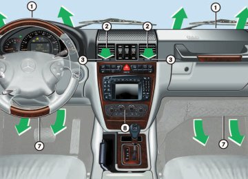
1 Cargo compartment lamps 2 Right reading lamp 3 Rocker switch for automatic control
system
4 Left reading lamp
If the door remains open, the interior lamps switch off automatically after ap- proximately five minutes.
Automatic control 왘 Move rocker switch 3 to center posi-
tion. Interior lamps are switched on in dark- ness, when: 앫 unlocking the vehicle 앫 opening a door 앫 removing the key from the starter
switch
In addition, the entry lamps in the door trays will come on when you open a door. The interior lamps are switched off fol- lowing an adjustable time delay (컄 page 126).
Deactivating 왘 Press the ñ symbol on rocker
switch 3. The interior lighting and the entry lamps remain switched off in darkness, even when you 앫 unlock the vehicle 앫 open a door 앫 remove the key from the starter
switch
Manual control
Switching lamps on 왘 Press the ð symbol on rocker
switch 3. The interior lighting remains on even when the doors are closed.
Switching lamps off 왘 Move rocker switch 3 to center posi- tion to activate the automatic control.
To prevent the vehicle battery from be- ing discharged, all interior lamps switch off automatically after approxi- mately 30 minutes with the tailgate open. If an interior lamp is switched on man- ually, it does not go out automatically. Before leaving the vehicle, make sure that the interior lamps are switched off.
Controls in detail Lighting
The rear interior lamps can be switched on with the SmartKey in starter switch position 0 or key removed from the starter switch for up to 30 minutes.
Rear interior lamps
The rear interior lamps are located above the rear seat bench on the left and right side.
1 The lamps are switched on
continuously
2 The lamps are switched off 3 Automatic function
105
Controls in detail Lighting
Cargo compartment lamps
Switching on and off
1 Switch for cargo compartment lamps 왘 Press button ò to switch the cargo
compartment lamps 2 on/off.
2 Cargo compartment lamps
Switching on and off with the tailgate open If the tailgate should remain open for a longer period of time, the cargo compart- ment lamps may be switched off separate- ly.
1 Door lock 2 Lock cylinder
Switching off 왘 Open the tailgate. 왘 Press door lock 1 down until it clicks
into place (arrow).
Do not close the tailgate if the lock is engaged in down position. The lock could otherwise be damaged. When locking the tailgate, it is impor- tant that the door lock be in the same position as shown in the illustration.
106
Switching on 왘 Press lock cylinder 2 to activate the
cargo compartment lamps again. The cargo compartment lamps will switch on.
Warning!
To prevent possible personal injury, always keep hands and fingers away from the tail- gate opening when closing the tailgate. Be especially careful when small children are around.
Only drive with the tailgate closed as other- wise exhaust fumes may enter the vehicle interior.
Controls in detail Lighting
107
Controls in detail Instrument cluster Instrument cluster A full view illustration of the instrument cluster can be found in the “At a glance” section of this manual (컄 page 24).
1 Reset knob The instrument cluster is activated when you: 앫 open a door 앫 turn on the ignition 앫 press reset knob 1
앫 switch on the exterior lamps You can change the instrument cluster set- tings in the Instrument cluster submenu of the control system (컄 page 122).108
Instrument cluster illumination
Use the reset knob to adjust the illumina- tion brightness for the instrument cluster.
The instrument cluster illumination is dimmed or brightened automatically to suit ambient light conditions. The instrument cluster illumination will also be adjusted automatically when you switch on the vehicle’s exterior lamps.
To brighten illumination 왘 Turn reset knob 1 in the instrument
cluster clockwise. The instrument cluster illumination will brighten.
To dim illumination 왘 Turn reset knob 1 in the instrument
cluster counterclockwise. The instrument cluster illumination will dim.
Coolant temperature display
Warning!
앫 Driving when your engine is badly over-
heated can cause some fluids which may have leaked into the engine com- partment to catch fire. You could be se- riously burned
앫 Steam from an overheated engine can cause serious burns and can occur just by opening the engine hood. Stay away from the engine if you see or hear steam coming from it.
Turn off the engine, get out of the vehicle and do not stand near the vehicle until it cools down.
During severe operating conditions and stop-and-go city traffic, the coolant tem- perature may rise close to 248°F (120°C). The engine should not be operated with the coolant temperature above 248°F (120°C). Doing so may cause serious en- gine damage which is not covered by the Mercedes-Benz Limited Warranty.
Trip odometer
왘 Make sure you are viewing the trip
odometer and main odometer (컄 page 111) in the multifunction dis- play.
왘 Press and hold the reset knob on the in- strument cluster (컄 page 108) until the trip odometer is reset.
왘 Turn the SmartKey in the starter switch
to position 1 or 2.
왘 Call up the trip odometer and main odometer by pressing button è or ÿ on the multifunction steering wheel (컄 page 112).
왘 Press button j or k until the coolant temperature display appears.
Excessive coolant temperatures trigger a warning in the multifunction display (컄 page 252).
Controls in detail Instrument cluster
Tachometer
The red marking on the tachometer de- notes excessive engine speed.
Avoid driving at excessive engine speeds, as it may result in serious en- gine damage that is not covered by the Mercedes-Benz Limited Warranty.
To help protect the engine, the fuel supply is interrupted if the engine is operated within the red marking.
109
The temperature sensor is located in the front bumper area. Due to its location, the sensor can be affected by road or engine heat during idling or slow driving. This means that the accuracy of the displayed temperature can only be verified by com- parison to a thermometer placed next to the sensor, not by comparison to external displays (e.g. bank signs, etc.).
When moving the vehicle into colder ambi- ent temperatures (e.g. when leaving your garage), you will notice a delay before the lower temperature is displayed. A delay also occurs when ambient temper- atures rise. This prevents inaccurate tem- perature indications caused by heat radiated from the engine during idling or slow driving.
Controls in detail Instrument cluster
Outside temperature indicator
Warning!
The outside temperature indicator is not de- signed to serve as an ice-warning device and is therefore unsuitable for that purpose.
Indicated temperatures just above the freez- ing point do not guarantee that the road sur- face is free of ice. The road may still be icy, especially in wooded areas or on bridges.
110
Control system The control system is activated as soon as the key in the starter switch is turned to position 1. The control system enables you to 앫 call up information about your vehicle 앫 change vehicle settings For example, you can use the control sys- tem to find out when your vehicle is next due for service, to set the language for messages in the instrument cluster display and much more.
Controls in detail Control system
Warning!
Multifunction display
A driver’s attention to the road and traffic conditions must always be his/her primary focus when driving.
For your safety and the safety of others, se- lecting features through the multifunction steering wheel should only be done by the driver when traffic and road conditions per- mit it to be done safely.
Bear in mind that at a speed of just 30 mph (approximately 50 km/h), your vehicle is covering a distance of 44 feet (approximate- ly 13.5 m) every second.
The control system relays information to the multifunction display.
1 Trip odometer 2 Main odometer 3 Outside temperature 4 Clock1
5 Current gear selector lever position 6 Transfer case program mode1 See separate operating
instructions
for the
COMAND system for clock setting.
111
Controls in detail Control system
Multifunction steering wheel
The displays in the multifunction display and the settings in the control system are controlled by the buttons on the multifunc- tion steering wheel.
112
Pressing any of the buttons on the multi- function steering wheel will alter what is shown in the multifunction display. The information available in the multifunc- tion display is arranged in menus, each containing a number of functions or sub- menus. The individual functions are then found within the relevant menu (radio or CD op- erations under AUDIO, for example). These functions serve to call up relevant informa- tion or to customize the settings for your vehicle.
1 Multifunction display in the speed-
ometer Operating the control system
2 Selecting the submenu or setting
the volume ç down / to decrease æ up / to increase
3 Telephone*
í to take a call ì to end a call
4 Menu systems
è for next menu ÿ for previous menu
5 Moving within a menu j for next display k for previous display
Controls in detail Control system
The menus are described on the following pages.
It is helpful to think of the menus, and the functions within each menu, as being ar- ranged in a circular pattern. 앫 If you press button è or ÿ
repeatedly, you will pass through each menu one after the other.
앫 If you press button k or j
repeatedly, you will pass through each function display, one after the other, in the current menu.
In the SETTINGS menu, instead of functions you will find a number of submenus for calling up and changing settings. For in- structions on using these submenus, see the “Settings menu” section (컄 page 119). The number of menus available in the sys- tem depends on which optional equipment is installed in your vehicle.
113
Controls in detail Control system
Menus
This is what you will see when you scroll through the menus.
The table on the next page provides an overview of the individual menus.
114
Menus, submenus and functions
Menu 1
Standard display Coolant temperature displayMenu 2
AUDIOMenu 3
NAVISelect radio station
Activate route guidance
Menu 4
Malfunction memory Call up malfunction messagesDigital speedometer
Operate CD player
Call up FSS
Check engine oil level
Controls in detail Control system
Menu 5
SettingsMenu 6
Trip computerMenu 7
TelephoneLoad phone book
Search for name in phone book
Fuel consumption statistics after start Fuel consumption statistics since the last reset Call up range
Reset to factory settings
Instrument cluster submenu
Lighting submenu Vehicle submenu
Convenience submenu
115
Controls in detail Control system
The headings used in the menus table are designed to facilitate navigation within the system and are not neces- sarily identical to those shown in the control system displays. The first function displayed in each menu will automatically show you which part of the system you are in.
116
Standard display menu
AUDIO menu
The functions in the AUDIO menu operate the audio equipment which you currently have turned on. If no audio equipment is currently turned on, the message AUDIO OFF is shown in the display. The following functions are available:
Function Select radio station Operate CD player
Page 117
117You can select the functions in the stan- dard display menu with button k or j. The following functions are available:
Function Call up coolant temperature display Call up digital speedometer
Call up FSS Check engine oil level
Page 108
see below 230
218Display digital speedometer 왘 Press button j twice.
The current vehicle speed is shown in the multifunction display.
Controls in detail Control system
Select radio station 왘 Turn on the radio. Refer to separate op-
erating instructions.
왘 Press button è or ÿ repeatedly
until you see the currently tuned sta- tion in the display.
왘 Press button k or j repeatedly
until the desired station is found. The type of search depends on the set- ting for the station tuning: 앫 The next stored station is selected
(SP)
앫 Station search
Operate the CD player 왘 Turn on the radio and select the CD
player. Refer to separate operating in- structions.
왘 Press button è or ÿ repeatedly until the settings for the CD currently being played are shown in the display.
1 Station 2 Waveband setting 3 Setting for station selection using
memory
You can only store new stations by us- ing the corresponding feature on the radio. Refer to separate operating in- structions. You can also operate the radio in the usual manner.
1 Current track 2 Current CD (for CD changer) 왘 Press button k or j repeatedly
until the desired track is selected.
To select a CD from the magazine, press a number on the COMAND sys- tem key pad located in the center dash- board.
117
Controls in detail Control system
NAVI menu
Malfunction memory menu
The NAVI menu contains the functions needed to operate your navigation system. 왘 Press button è or ÿ repeatedly until you see the message NAVI in the display.
앫 If the navigation system is off, the mes- sage NAVI OFF is shown in the display. 앫 If the navigation system is on, the mes- sage NAVI ACTIVE is shown in the dis- play.
Please refer to the COMAND manual for in- structions on how to activate the route guidance system*.
Use the malfunction memory menu to scan malfunction and warning messages that may be stored in the system. The informa- tion shown in the display depends on whether malfunctions have actually oc- curred.
Warning!
Malfunction and warning messages are only indicated for certain systems and are inten- tionally not very detailed. The malfunction and warning messages are simply a remind- er with respect to the operation of certain systems and do not replace the owner’s and/or driver’s responsibility to maintain the vehicle’s operating safety by having all required maintenance and safety checks performed on the vehicle and by bringing the vehicle to an authorized Mercedes-Benz Light Truck Center to address the malfunc- tion and warning messages (컄 page 246).
118
왘 Press button è or ÿ repeatedly until you see the malfunction message memory in the display.
No malfunction messages If no malfunctions have occurred, the mes- sage in the display is: NO MALFUNCTION
Malfunctions have occurred If malfunctions have occurred, you will see the number of malfunctions in the display:
1 Number of malfunctions 왘 Press button k or j.
The stored messages will now be dis- played in order. See the “Practical hints” section for malfunction and warning messages (컄 page 246).
Should any malfunctions occur while driv- ing, the number of malfunctions will reap- pear in the display when the key in the starter switch is turned to position 0 or re- moved from the starter switch.
The message memory will be cleared when you turn the key in the starter switch to position 1 or 2. You will then only see Priority 1 malfunctions (컄 page 246).
Settings menu
In the SETTINGS menu there are two func- tions: 앫 The function RETURN TO FACTORY SET- TINGS, with which you can reset all the settings to those set at the factory.
앫 A collection of submenus with which you can make individual settings for your vehicle.
왘 Press button è or ÿ repeatedly until the SETTINGS menu is seen in the display.
Controls in detail Control system
Resetting all settings You can reset all the functions of all sub- menus to the factory settings. 왘 Press the reset knob in the instrument cluster (컄 page 24) for approximately three seconds. In the display you will see the request to press the reset knob again to con- firm.
왘 Press the reset knob (컄 page 24)
again. The functions of all the submenus will reset to factory settings.
The settings you have changed will not be reset unless you confirm the action by pressing the reset knob a second time.
119
Controls in detail Control system
Submenus in the Settings menu 왘 Press button k or j.
In the display you see the collection of the submenus.
왘 Press button ç.
The selection marker moves to the next submenu.
The submenus are arranged by hierarchy. Scroll down with the ç button, scroll up with the æ button. Move within the submenus with the k or j button to the individual functions. The settings themselves are made with button æ or ç.
Resetting the functions of a submenu For each submenu you can reset all the functions to the factory settings. 왘 Move to a function in the submenu. 왘 Press the reset knob in the instrument cluster (컄 page 24) for approximately three seconds. In the display you will see the request to press the reset knob again to con- firm.
왘 Press the reset knob (컄 page 24)
again. All functions of the submenu will reset to factory settings
120
Controls in detail Control system
The table below shows what settings can be changed within the various menus. De- tailed instructions on making individual settings can be found on the following pag- es.
INSTRUMENT CLUSTER Select temperature display mode Select speedometer display mode Select language
Select display (speed display or outside temperature)
LIGHTING Set daytime running lamp mode (USA only) Set locator lighting
VEHICLE Set station selection mode (radio) Set automatic locking
Exterior lamps delayed switch-off Interior lighting delayed switch-off
CONVENIENCE Activate easy-entry/exit feature
Set key dependency
Set parking position for exterior rear view mirror
121
Controls in detail Control system
Instrument cluster submenu Access the INSTRUMENT CLUSTER menu via the SETTINGS menu. Use the INSTRUMENT CLUSTER submenu to change the instru- ment cluster display settings. The follow- ing functions are available:
Function Select temperature display mode Select speedometer display mode Select language Select display (speed display or outside temperature)
Page see be- low see be- low 123
123122
Selecting temperature display mode 왘 Move the selection marker with
the æ or ç button to the IN- STRUMENT CLUSTER submenu.
Selecting speedometer display mode 왘 Move the selection marker with
the æ or ç button to the IN- STRUMENT CLUSTER submenu.
왘 Press button j or k repeatedly
왘 Press button j or k repeatedly
until you see this message in the dis- play: TEMP. INDICATOR. The selection marker is on the current setting.
until you see this message in the dis- play: DISPLAY VALUES IN. The selection marker is on the current setting.
왘 Press æ or ç to set temperature unit to degrees Celsius (°C) or degrees Fahrenheit (°F).
왘 Press æ or ç to set speedome-
ter unit to km or miles.
Controls in detail Control system
Selecting language 왘 Move the selection marker with
the æ or ç button to the IN- STRUMENT CLUSTER submenu.
왘 Press button j or k repeatedly
until you see this message in the dis- play: TEXT. The selection marker is on the current setting.
왘 Press æ or ç to select the lan-
guage to be used for the multifunction display messages. Available languages: 앫 German 앫 English 앫 French 앫 Italian 앫 Spanish
Selecting display (speed display or out- side temperature) 왘 Move the selection marker with
the æ or ç button to the IN- STRUMENT CLUSTER submenu.
왘 Press button j or k repeatedly
until you see this message in the dis- play: SELECT DISPLAY. The selection marker is on the current setting.
왘 Press æ or ç to select the dis- play permanently shown in the multi- function display.
123
Controls in detail Control system
Lighting submenu Access the LIGHTING submenu via the SET- TINGS menu. Use the LIGHTING submenu to change the lamp and lighting settings on your vehicle. The following functions are available:
Function Set daytime running lamp mode (USA only) Set locator lighting Exterior lamps delayed switch-off Interior lighting delayed switch-off
Page see below 125
125126
124
Setting daytime running lamp mode (USA only) 왘 Move the selection marker with
the æ or ç button to the LIGHT- ING submenu.
왘 Press button j or k repeatedly
until you see this message in the dis- play: LIGHT CIRCUIT HEADLAMP MODE. The selection marker is on the current setting.
왘 Press æ or ç to select manual
or daytime running lamp (constant) mode. This function is not available in countries where daytime running lamps are mandatory.
With daytime running lamp mode se- lected and the exterior lamp switch at position 0, the following lamps will come on automatically when the en- gine is turned on: 앫 Parking lamps and low beam head-
lamps
앫 License plate lamps
If you turn the exterior lamp switch to another position, the corresponding lamp(s) will switch on. For safety reasons, resetting the LIGHTING submenu to factory settings (컄 page 120) will not reset the daytime running lamp mode. In the display you will then see the mes- sage: LIGHTING – CANNOT BE COM- PLETELY RESET TO FACTORY SETTINGS WHILE DRIVING.
Setting locator lighting During darkness, the following lamps will come on when the exterior lamp switch is in position U, the locator lighting fea- ture is activated, and the vehicle is un- locked by remote control: 앫 parking lamps 앫 tail lamps 앫 license plate lamps 앫 front fog lamps The locator lighting switches off when the driver’s door is opened. It switches off au- tomatically after a period of approximately 40 seconds. 왘 Move the selection marker with the æ or ç button to the LIGHTING submenu.
왘 Press button j or k repeatedly
until you see this message in the dis- play: LOCATOR LIGHTING. The selection marker is on the current setting.
왘 Press æ or ç to select the de-
sired setting. The locator lighting will be switched on or off.
Controls in detail Control system
Setting night security illumination (Exterior lamps delayed switch-off) Use the HEADLAMPS DELAYED SWITCH-OFF function to set whether and for how long you would like the exterior lamps to illumi- nate during darkness after all doors are closed. When the delayed shut-off feature is activated and the exterior lamp switch is in position U, the following lamps will remain lit after you remove the key from the starter switch: 앫 parking lamps 앫 tail lamps 앫 license plate lamps 앫 front fog lamps
125
왘 Press æ or ç to select the de-
sired lamp-on period. You can select: 앫 0 s, the delayed switch-off feature
is deactivated
앫 15 s, 30 s, 45 s or 60 s, the delayed
switch-off feature is activated
You can temporarily deactivate the de- layed switch-off feature: 왘 Before leaving the vehicle, turn the key
in the starter switch to position 0. 왘 Then turn it to position 2 and back
to 0. The delayed switch-off feature is deac- tivated. It will reactivate as soon as you reinsert the key in the starter switch.
Interior lighting delayed switch-off Use this function to set whether and for how long you would like the interior light- ing to remain lit during darkness after the key is removed from the starter switch. 왘 Move the selection marker with
the æ or ç button to the LIGHT- ING submenu.
왘 Press button j or k repeatedly
until you see this message in the dis- play: INT. LIGHTING DELAYED SWITCH-OFF. The selection marker is on the current setting.
Controls in detail Control system
You can reactivate this function within ten minutes by opening a door. If you do not open a door after remov- ing the key, the lamps will automatical- ly switch off after 60 seconds.
왘 Move the selection marker with
the æ or ç button to the LIGHT- ING submenu.
왘 Press button j or k repeatedly
until you see this message in the dis- play: HEADLAMPS DELAYED SWITCH-OFF. The selection marker is on the current setting.
126
Controls in detail Control system
Vehicle submenu Access the VEHICLE submenu via the SETINGS menu. Use the VEHICLE submenu to make general vehicle settings. The fol- lowing functions are available:
왘 Press button j or k repeatedly
until you see this message in the dis- play: PRESS BUTTON IN AUDIO MODE. The selection marker is on the current setting.
왘 Press æ or ç to select the de-
sired lamp-on time period. You can se- lect: 앫 0 s, the delayed switch-off feature
is deactivated
앫 5 s, 10 s, 15 s or 20 s, the delayed
switch-off feature is activated
Function Set station selection mode (radio) Set automatic locking
Page see below 128
Setting station selection mode Use the PRESS BUTTON IN AUDIO MODE function to select the manual or memory station selection mode for the radio. 왘 Move the selection marker with the æ or ç button to the VEHICLE submenu.
왘 Press æ or ç to select the de- sired station selection mode. You can select: 앫 STATION SEARCH 앫 MEMORY selects next stored station
127
Controls in detail Control system
Setting automatic locking Use this function to activate or deactivate the automatic central locking. With the au- tomatic central locking system activated, the vehicle is centrally locked at vehicle speeds of approximately 9 mph (15 km/h). 왘 Move the selection marker with
the æ or ç button to the Vehicle submenu.
왘 Press button j or k repeatedly
until you see this message in the dis- play: AUTOMATIC DOOR LOCK. The selection marker is on the current setting.
왘 Press æ or ç to switch
AUTOMATIC DOOR LOCK ON or OFF.
128
Warning!
Make sure that no one can become trapped or injured by the moving steering wheel when the easy-entry/exit feature is in oper- ation and the driver’s door is being opened or the key is removed from the starter switch. Do not leave children unattended in the vehicle, or with access to an unlocked vehicle. Unsupervised use of vehicle equip- ment may cause in an accident and/or seri- ous personal injury.
Do not leave children unattended in the ve- hicle, or with access to an unlocked vehicle. Children could open the driver’s door and unintentionally activate the easy-entry/exit feature, which could result in an accident and/or serious personal injury.
Convenience submenu Access the CONVENIENCE submenu via the SETTINGS menu. Use the CONVENIENCE sub- menu to change the settings for a number of convenience features. The following functions are available:
Function Page Activate easy-entry/exit feature see
Set key dependency Set parking position for exterior rear view mirror
below 129
130Activating easy-entry/exit feature Use this function to activate and deacti- vate the easy-entry/exit feature. When the feature is activated, the steering wheel will move back to facilitate exiting when you 앫 remove the key from the starter switch 앫 open the driver’s door However, the engine must be turned off.
After entering the vehicle, the steering wheel will move into the position stored in memory when 앫 the driver’s door is closed 앫 you put the key in the starter switch
and
앫 press the appropriate stored position
button on the memory switch (컄 page 99)
To cancel steering wheel movement, do one of the following: 앫 move the steering column stalk
(컄 page 22)
앫 press the memory switch
(컄 page 98)
왘 Move the selection marker with
the æ or ç button to the CONVE- NIENCE submenu.
왘 Press button j or k repeatedly
until you see this message in the dis- play: EASY-ENTRY FEATURE ACTIVATE.
The selection marker is on the current setting.
왘 Press æ or ç to change the
easy-entry/exit setting.
The following settings are available for the easy-entry/exit feature
OFF
STEERING COLUMN
The easy-entry/exit feature is deactivat- ed The easy-entry/exit feature is activated
Controls in detail Control system
Setting key dependency Use this function to set whether the mem- ory settings for the seats, the steering wheel and the mirrors should be stored separately for each key (컄 page 97). 왘 Move the selection marker with
the æ or ç button to the CONVE- NIENCE submenu.
왘 Press button j or k repeatedly
until you see this message in the dis- play: SETTINGS KEY-DEPENDENT. The selection marker is on the current setting.
왘 Press æ or ç to set key depen-
dency to ON or OFF.
129
Controls in detail Control system
Setting parking position for exterior rear view mirror Use the MIRROR SETTING WHEN PARKING function to select whether the passen- ger-side exterior rear view mirror should be turned downward during parking maneu- vers, when reverse gear is engaged. For additional information, see “Activating ex- terior rear view mirror parking position” (컄 page 148). 왘 Move the selection marker with
the æ or ç button to the CONVE- NIENCE submenu.
왘 Press button j or k repeatedly
until you see this message in the dis- play: MIRROR SETTING WHEN PARKING. The selection marker is on the current setting.
130
Fuel consumption statistics after start 왘 Press button ÿ or è repeatedly
until you see the first function of the Trip computer menu.
왘 Press button j or k repeatedly until you see this message in the multi- function display: AFTER START.
1 Time elapsed since start 2 Average fuel consumption since start 3 Average speed since start 4 Distance driven since start
왘 Press æ or ç to switch function
ON or OFF.
Trip computer menu
Use the trip computer menu to call up sta- tistical data on your vehicle. The following information is available:
Page 130
Function Fuel consumption statistics after start Fuel consumption statistics since last reset Call up range (distance to empty) 131
131
Fuel consumption since last reset 왘 Press button ÿ or è repeatedly
until you see the first function of the Trip computer menu.
왘 Press button j or k repeatedly
until you see this message in the dis- play: AFTER RESET.
1 Time elapsed since last reset 2 Average fuel consumption since last re-
set
3 Average speed since last reset 4 Distance driven since last reset
All statistics stored since the last en- gine start will be reset approximately four hours after the key in the starter switch is turned to position 0 or re- moved from the starter switch. Resetting will not occur if you turn the key back to position 1 or 2 within this time period.
Resetting fuel consumption statistics 왘 Press button ÿ or è repeatedly
until you see the first function of the Trip computer menu.
왘 Press button j or k repeatedly until you see the reading that you want to reset in the display.
왘 Press and hold the reset knob in the in- strument cluster (컄 page 24) until the value is reset to 0.
Controls in detail Control system
Call up range (distance to empty) 왘 Press button ÿ or è repeatedly
until you see the first function of the Trip computer menu.
왘 Press button j or k repeatedly
until you see this message in the dis- play: RANGE. In the display you will see the calculat- ed range based on the current fuel tank level.
131
Controls in detail Control system
TEL menu
Warning!
A driver’s attention to the road and traffic conditions must always be his/her primary focus when driving. For your safety and the safety of others, we recommend that you pull over to a safe location and stop before placing or taking a telephone call. If you choose to use the telephone while driving, please use the hands-free device and only use the telephone when road and traffic conditions permit.
Some jurisdictions prohibit the driver from using a cellular telephone while driving a ve- hicle.
Bear in mind that at a speed of just 30 mph (approximately 50 km/h), your vehicle is covering a distance of approximately 44 feet (approximately 13.5 m) every sec- ond.
132
앫 If the telephone is on:
The telephone will then search for a network. During this time the display is empty. As soon as the telephone has found a network, READY is indicated in the dis- play.
1 Signal strength This standby message indicates that your telephone is ready for use and you can op- erate it using the control system.
Never operate radio transmitters equipped with a built-in or attached antenna (i.e. with- out being connected to an external antenna) from inside the vehicle while the engine is running. Doing so could lead to a malfunc- tion of the vehicle’s electronic system, pos- sibly resulting in an accident and/or personal injury.
You can use the functions in the TEL menu to operate your telephone, provided it is connected to a hands-free system and switched on. 왘 Switch on the telephone and COMAND. 왘 Press button ÿ or è on the
steering wheel repeatedly until you see the TEL menu in the display.
Which messages will appear in the display field depends on whether your telephone is switched on or off: 앫 If the telephone is off, the message in the multifunction display is: TEL OFF.
Answering a call When your telephone is ready to receive calls, you can answer a call at any time. In the display you will then see the message:
왘 Press button í.
You have answered the call. In the dis- play you see the length of the call.
Ending a call 왘 Press button ì.
You have ended the call. In the display you will again see the standby mes- sage.
Dialing a number from the phone book If your telephone is ready to receive calls, you may select and dial a number from the phone book at any time. 왘 Press button ÿ or è repeatedly until you see the TEL menu in the dis- play.
왘 Press button j or k.
The control system reads the phone book which is stored in the telephone. This may take up to 30 seconds. In the display you will see the message PLEASE WAIT!. When the message PLEASE WAIT! dis- appears, the phone book has been loaded.
왘 Press button j or k repeatedly until the desired name appears in the display. The stored names are displayed in in- creasing or decreasing alphabetical or- der.
Controls in detail Control system
If you press and hold j or k for longer than one second, the system scrolls rapidly through the list of names until you release the button again. Cancel the quick search mode by pressing ì.
왘 Press button í.
The system dials the selected phone number. 앫 If connection is successful, the
name of the party you called and the duration of the call will appear in the display.
133
왘 Press button í.
In the display, you see the first number in the redial memory.
왘 Press button j or k repeatedly until the desired name appears in the display.
왘 Press button í.
The control system dials the selected phone number.
Controls in detail Control system
앫 If no connection is made, the con- trol system stores the dialed num- ber in the redial memory.
Redialing The control system stores the most recent- ly dialed phone numbers. This eliminates the need to search through your entire phone book. 왘 Press button ÿ or è repeatedly until you see the TEL menu in the dis- play.
134
Automatic transmission Information for driving with an automatic transmission is found in the “Getting start- ed” section (컄 page 43). Your transmission adapts its gear shifting process to your individual driving style by continually adjusting the shift points up or down. These shift point adjustments are performed based on current operating and driving conditions. If the operating conditions change, the au- tomatic transmission reacts by adjusting its gear shift program.
Controls in detail Automatic transmission
The automatic transmission selects indi- vidual gears automatically, dependent upon 앫 the selector lever position D with gear
ranges 4, 3, 2, 1 (컄 page 137)
앫 transfer case position (HIGH or LOW) 앫 the position of the accelerator pedal
(컄 page 139)
앫 the vehicle speed
135
Controls in detail Automatic transmission
The current selector lever position and the transfer case position (HIGH or LOW) ap- pear in the tachometer display.
1 Transfer case display 2 Selector lever position/gear range
When the selector lever is in position D, you can influence transmission shifting by 앫 limiting the gear range 앫 changing gears yourself
One-touch gearshifting
Even with an automatic transmission, you can change the gears yourself when the selector lever is in position D.
Warning!
Downshifting 왘 Briefly press the selector lever to the
left in the D– direction.
The transmission will shift from the current gear to the next lower gear. This action si- multaneously limits the gear range of the transmission (컄 page 137).
It is dangerous to shift the selector lever out of P or N if the engine speed is higher than idle speed. If your foot is not firmly on the brake pedal, the vehicle could accelerate quickly forward or reverse. You could lose control of the vehicle and hit someone or something. Only shift into gear when the en- gine is idling normally and when your right foot is firmly on the brake pedal.
136
Warning!
On slippery road surfaces, never downshift in order to obtain braking action. This could result in drive wheel slip and reduced vehi- cle control. Your vehicle’s ABS will not pre- vent this type of loss of control.
To avoid overrevving the engine when the selector lever is moved to the D– direction, the transmission will not shift to a lower gear if the engine's max. speed would be exceeded.
Upshifting 왘 Briefly press the selector lever to the
right in the D+ direction.
The transmission will shift from the current gear to the next higher gear as permitted by the shift program. This action simulta- neously extends the gear range of the transmission.
Canceling gear range limit 왘 Press and hold the selector lever in the
D+ direction until D reappears in the tachometer display field.
The transmission will shift from the current gear range directly to gear range D.
Shifting into optimal gear range 왘 Press and hold the gear selector lever
in the D– direction.
The transmission will automatically select the gear range suited for optimal accelera- tion and deceleration. This will involve shifting down one or more gears.
Gear ranges
With the selector lever in position D, you can limit the transmission’s gear range by pressing the lever to the left (D-), and re- verse the gear range limit by pressing the lever to the right (D+). The selected gear range will appear in the tachometer display field. If you press on the accelerator when the engine has reached its rpm limit, the transmission will upshift beyond any gear range limit selected.
If the transfer case is in off-road driving position LOW, the automatic transmis- sion will not shift up automatically, even when the engine has reached the speed limit for that gear. There is a risk of damaging the engine. It is very important to make sure that the permissible engine speed is not ex- ceeded.
Controls in detail Automatic transmission
Effect
Gear range é The transmission shifts through fourth gear only. è The transmission shifts through third gear only. With this selection you can use the braking effect of the engine.
137
Controls in detail Automatic transmission
Effect
Gear range ç The transmission shifts
through second gear only. Allows the use of engine’s braking power when driving 앫 on steep downgrades 앫 in mountainous regions 앫 under extreme operating
conditions
æ The transmission operates
only in first gear For maximum use of engine’s braking effect on very steep or lengthy downgrades.
Gear selector lever position
Effect Park position Selector position when the vehicle is parked. Only place selector lever in position P when vehicle is stopped. The park position is not intended to serve as a brake when the vehicle is parked. Rather, the driver should al- ways set the parking brake in addi- tion to placing the selector lever in position P to secure the vehicle. The key can only be removed from the starter switch with the selector lever in position P. With the key re- moved, the selector lever is locked in position P.
R Reverse gear
Place selector lever in position R only when vehicle is stopped.
138
Effect
N Neutral
No power is transmitted from the en- gine to the drive axle. When the brakes are released, the vehicle can be moved freely (pushed or towed). Do not engage N while driving ex- cept: 앫 to coast when the vehicle is in danger of skidding (e.g. on icy roads) when the ESP is deactivat- ed or malfunctioning
앫 when you have to shift the trans-
fer case
D Drive
The transmission shifts automatical-