- Download PDF Manual
-
The synchronization must be repeated if the panorama sliding/pop-up roof cannot be fully opened (Express-open).
Solar panel*
A solar panel is available in combination with the panorama sliding/pop-up roof. The solar cells convert natural light into electrical energy. When the engine is switched off, the energy generated auto- matically switches on the ventilation fan. The constant air flow creates a cooler tem- perature for cars parked in the sunlight. The air flow depends on the intensity of the solar radiation. The ventilation starts two minutes after switching off the engine.
210
왔 Driving systems The following driving systems are ex- plained on the following pages: 앫 Cruise control and Distronic*, with
which the vehicle can maintain a preset speed
앫 Airmatic* adjusts the vehicle suspen- sion characteristics automatically and controls the vehicle level
앫 Parktronic system*, which assists the
driver during parking maneuvers
The BAS, ABS, ESP and SBC are described in the “Safety and Security” section (컄 page 74).
Cruise control
The cruise control automatically maintains the speed you set for your vehicle. Use of cruise control is recommended for driving at a constant speed for extended periods of time. You can set any speed over 20 mph (30 km/h). The cruise control function is operated by means of the cruise control lever. The cruise control lever is the uppermost lever found on the left-hand side of the steering column (컄 page 20).
Controls in detail Driving systems
Warning!
Cruise control is a convenience system de- signed to assist the driver during vehicle op- eration. The driver is and must always remain responsible for the vehicle speed and for safe brake operation.
Only use cruise control if the road, traffic and weather conditions make it advisable to travel at a steady speed. 앫 The use of cruise control can be danger- ous on winding roads or in heavy traffic because conditions do not allow safe driving at a steady speed.
앫 The use of cruise control can be danger- ous on slippery roads. Rapid changes in tire traction can result in wheel spin and loss of control.
앫 Deactivate cruise control when driving
in fog.
The “Resume” function should only be oper- ated if the driver is fully aware of the previ- ously set speed and wishes to resume this particular preset speed.
211
! Moving gear selector lever to position N while driving also cancels cruise control. However, the gear se- lector lever should not be moved to position N while driving except to coast when the vehicle is in danger of skid- ding (e.g. on icy roads).
The last stored speed is canceled when you turn off the engine.
On uphill or downhill grades, cruise control may not be able to maintain the set speed. Once the grade eases, the set speed will be resumed.
Canceling cruise control There are several ways to cancel cruise control: 왘 Step on the brake pedal. or 왘 Briefly push the cruise control lever to
position 3. Cruise control will be canceled. The last speed set will be stored for later use.
Controls in detail Driving systems
1 Set current or higher speed 2 Set current or lower speed 3 Cancel cruise control 4 Resume at previously set speed
Saving current speed 왘 Accelerate or decelerate to the desired
speed.
왘 Briefly lift 1 or depress 2 the cruise
control lever. The current speed is set.
왘 Remove your foot from the accelerator
pedal. Cruise control is activated.
212
Setting stored speed (“Resume” function)
Setting a higher speed 왘 Lift the cruise control lever to
Warning!
position 1 and hold it up until the de- sired speed is reached.
The speed stored in memory should only be set again if prevailing road conditions per- mit. Possible acceleration or deceleration differences arising from returning to preset speed could cause an accident and/or seri- ous injury to you and others.
왘 Briefly push the cruise control lever to
position 4. The cruise control will resume the last previously set speed.
왘 Remove your foot from the accelerator
pedal.
왘 Release the cruise control lever.
The new speed is set.
Depressing the accelerator pedal does not deactivate cruise control. After brief acceleration (e.g. for passing), cruise control will resume the last speed set.
Setting a lower speed 왘 Depress the cruise control lever to
position 2 and hold it down until the desired speed is reached.
왘 Release the cruise control lever.
The new speed is set.
Controls in detail Driving systems
When you use the cruise control lever to decelerate, the transmission will au- tomatically downshift if the engine’s braking power does not brake the vehi- cle sufficiently.
Fine adjustment in 1 mph (Canada: 1 km/h) increments
Faster 왘 Briefly tip the cruise control lever in the
direction of arrow 1.
Slower 왘 Briefly tip the cruise control lever in the
direction of arrow 2.
213
Controls in detail Driving systems
Distronic*
When activated, the Distronic adaptive cruise control system increases driving convenience afforded by the cruise control during travel on expressways and other major roads. 앫 If the Distronic distance sensor detects a slower moving vehicle directly ahead, your vehicle speed will be reduced so that you follow that vehicle at a preset distance.
앫 If there is no vehicle directly ahead of you, Distronic will function in the same way as cruise control (컄 page 218).
Warning!
Distronic adaptive cruise control is no sub- stitute for active driving involvement. It does not react to stationary objects, nor recog- nize or predict the curvature and lane layout or the movement of vehicles ahead. Distronic can only apply a maximum of 20% of the vehicle’s braking power.
214
It is the driver’s responsibility at all times to be attentive to traffic and road conditions and to provide the steering, braking and oth- er driving inputs necessary to retain control of the vehicle.
Warning!
Distronic is a convenience system. Its speed adjustment reduction capability is intended to make cruise control more effective and usable when traffic speeds vary. However, it is not intended to, nor does it, replace the need for extreme care. The responsibility for the vehicle speed and the distance to the ve- hicle ahead, including most importantly brake operation to assure safe stopping dis- tance, always rests with the driver.
Distronic cannot take street and traffic con- ditions into account.
Warning!
Distronic requires familiarity with its opera- tional characteristics. We strongly recom- mend that you review the following information carefully before operating the system.
For operation in the USA only: This de- vice complies with Part 15 of the FCC Rules. Operation is subject to the following two conditions: 앫 this device may not cause harmful
interference, and
앫 this device must accept any inter- ference received, including interfer- ence that may cause undesired operation.
Any unauthorized modification to this device could void the user’s authority to operate the equipment.
Warning!
Warning!
Distronic cannot take street and traffic con- ditions into account. Only use Distronic if the road, weather and traffic conditions make it advisable to travel at a steady speed.
Warning!
Use of Distronic can be dangerous on slip- pery roads. Rapid changes in tire traction can result in wheel spin and loss of control.
Distronic does not act upon adverse sight distance conditions. Do not use Distronic during conditions of fog and heavy rain, snow or sleet.
Close attention to road and traffic condi- tions is imperative at all times, regardless of whether or not Distronic is activated.
Use of Distronic can be dangerous on wind- ing roads or in heavy traffic because condi- tions do not allow safe driving at a steady speed.
Distronic will not react to stationary objects in the roadway (e.g. a stopped vehicle in a traffic jam or a disabled vehicle). Distronic will also not respond to oncoming vehicles.
Switch off Distronic: 앫 when changing from the left to the right lane if vehicles are moving more slowly in the left lane
앫 when entering a turn lane or highway off
ramp
앫 in complex driving situations, such as in
highway construction zones
In these situations, Distronic will continue to maintain the set speed unless deactivated.
Controls in detail Driving systems
Distronic is designed and intended only to maintain a set speed and keep a set dis- tance from moving objects in front of it.
Warning!
The “Resume” function should only be oper- ated if the driver is fully aware of the previ- ously set speed and wishes to resume this particular preset speed.
215
Under no circumstances should the driver await the intermittent warning sound before braking. See the fallow- ing warning note. The intermittent warning sound ceases and the red DTR warning lamp l goes out when the necessary distance to the vehicle ahead is again estab- lished.
Controls in detail Driving systems
Distronic displays in the speedometer dial
1 Set speed If Distronic is activated, one or two seg- ments come on around the set speed.
The vehicle speed displayed on the speedometer can briefly vary from the speed setting on the Distronic system.
1 Segments If Distronic detects a vehicle directly ahead, the segments from the speed of the vehicle ahead to the set speed come on. If Distronic calculates that there is a dan- ger of collision: 앫 The DTR warning lamp l in the in-
strument cluster comes on red. 앫 An intermittent warning sounds. 왘 Immediately brake the vehicle to avoid
a collision.
216
Warning!
Warning!
An intermittent warning sounds and the DTR warning lamp in the instrument cluster is illuminated if the Distronic system calcu- lates that the distance to the vehicle ahead and your vehicle’s current speed indicate that Distronic will not be capable of slowing the vehicle sufficiently to maintain the pre- set following distance, which creates a dan- ger of a collision.
Immediately brake the vehicle to increase the distance to the vehicle in front of you. The warning sound is intended as a final cau- tion that you have not interceded with your own braking inputs to avoid a potentially dangerous situation. Do not wait for the op- eration of the warning signal to intercede with your own braking, as that will result in potentially dangerous emergency braking which will not always result in an impact be- ing avoided.
Tailgating increases the risk of an accident.
Distronic brakes your vehicle with a maxi- mum deceleration of 6.5 ft/s2 (2 m/s2). This corresponds to about 20% of the maxi- mum deceleration ability of your vehicle.
Distronic brakes the vehicle in an effort to restore the preset distance or to maintain the speed. The brake pedal is automatically applied as this happens which results in the brake pedal moving.
Keep driver’s foot area clear at all times, in- cluding the area under the brake pedal. Ob- jects stored in this area may impair pedal movement which could interfere with the braking ability of the Distronic system.
Do not place your foot under the brake pedal – your foot could become caught.
Controls in detail Driving systems
Distronic menu in the control system In the Distronic menu you can read the cur- rent settings for Distronic. What appears in the display depends on whether Distronic and the distance warning function are turned on or off. 왘 Press button è or ÿ repeatedly until you see one of the following dis- plays.
217
Controls in detail Driving systems
Distronic deactivated If Distronic is deactivated you can see the standard display of Distronic in the multi- function display.
Distronic activated If you turn Distronic on, you will see the set speed in the multifunction display for about five seconds. If Distronic is activated, you can see the following dis- play in the multifunction display.
Cruise control lever The Distronic system is operated by means of the cruise control lever. The cruise control lever is the uppermost lever found on the left-hand side of the steering column.
1 Vehicle ahead, if detected 2 Actual distance to vehicle ahead 3 Preset distance threshold to vehicle
ahead
4 Your vehicle 5 Symbol for activated distance warning
function
1 Distronic activated
1 Set current or higher speed 2 Set current or lower speed 3 Deactivate Distronic 4 Resume at previously set speed
218
Activating Distronic You can activate Distronic if: 앫 you are driving between 25 mph
(40 km/h) and 110 mph (180 km/h)
앫 the ESP is activated (컄 page 76) If Distronic has not been activated after pressing the cruise control lever you will see the message --- in the multifunction display. In the following cases you cannot activate Distronic: 앫 Up to two minutes after starting the en-
gine
앫 When you brake 앫 If you have set the parking brake 앫 If the gear selector lever is in
position P, R or N
앫 If the ESP is switched off
Setting the current speed 왘 Accelerate or decelerate to the desired
speed.
왘 Briefly lift or depress the cruise control
lever. Distronic is activated and the current speed is set.
왘 Remove your foot from the accelerator
pedal.
If you do not take your foot off of the accelerator completely, the following message will appear in the multifunc- tion display: Distronic override. The distance to a slower moving vehicles in front of you will not be set. Your vehicle speed will then be determined only by the accel- erator pedal position.
Controls in detail Driving systems
Setting a higher speed 왘 Briefly tip the cruise control lever in the direction of arrow 1 (컄 page 218) to increase vehicle speed in increments of 5 mph (Canada: 10 km/h). The new speed is set. The stored speed is displayed in the multifunction display for approximately five seconds (컄 page 218), and one or two segments around the stored speed come on on the speedometer (컄 page 216).
Depressing the accelerator pedal does not deactivate Distronic. After brief ac- celeration (e.g. for passing), cruise con- trol will resume the last speed set.
219
Controls in detail Driving systems
Setting a lower speed 왘 Briefly tip the cruise control lever in the direction of arrow 2 (컄 page 218) to decrease vehicle speed in increments of 5 mph (Canada: 10 km/h). The new speed is set. The stored speed is displayed in the multifunction display for approximately five seconds (컄 page 218), and one or two segments around the stored speed come on on the speedometer (컄 page 216).
When you use the cruise control lever to decelerate, the transmission will au- tomatically downshift if the rate of de- celeration is too low.
220
Fine adjustment in 1 mph (Canada: 1 km/h) increments
Setting stored speed (“Resume” function)
Faster 왘 Briefly tip the cruise control lever in the
direction of arrow 4 (컄 page 218).
Warning!
The speed stored in memory should only be set again if prevailing road conditions per- mit. Possible acceleration or deceleration differences arising from returning to preset speed could cause an accident and/or seri- ous injury to you and others.
왘 Briefly tip the cruise control lever in the
direction of arrow 4 (컄 page 218). Distronic is activated and set to the last stored speed.
왘 Remove your foot from the accelerator
pedal.
Controls in detail Driving systems
Deactivating Distronic There are several ways to deactivate the Distronic system: 왘 Briefly tip the cruise control lever in the
direction of arrow 3 (컄 page 218).
or 왘 Step on the brake pedal.
Distronic will be deactivated. The last speed set will be stored in memory.
The following message will appear in the multifunction display for approxi- mately five seconds: Distronic off. The last stored speed is deleted when you turn off the engine.
Distronic deactivates automatically when: 앫 you set the parking brake 앫 you drive slower than 25 mph
(40 km/h)
앫 the ESP is active (컄 page 76) or you de-
activate the ESP
앫 you move the transmission selector le-
ver into position N A signal will sound. The Distronic off message appears in the multifunction display for approximately five seconds.
Setting the following distance in Distronic You can set the specified following dis- tance for Distronic by varying the time set- ting between 1.0 and 2.0 seconds. Using this time setting and the current speed of your vehicle, Distronic calculates and sets the required following distance to the vehi- cle ahead. The set distance will be shown in the multifunction display field. The thumbwheel for making the time set- ting is located on the lower section of the center console.
Warning!
Warning!
Distronic switches off and releases the brakes when the vehicle decelerates below the minimum speed of approximately 25 mph (40 km/h) by operation of the sys- tem. At that time the driver must apply the brakes in order to reduce vehicle speed fur- ther or bring it to a stop.
It is up to the driver to exercise discretion to select the appropriate setting given road conditions, traffic, driver’s preferred driving style and applicable laws and driving recom- mendations for safe following distance.
221
Controls in detail Driving systems
1 Distance warning function on/off
switch
2 Control lamp 3 Thumbwheel for setting distance
Increasing distance Increasing the distance setting tells Distronic to maintain a greater following distance to the vehicle ahead. 왘 Turn thumbwheel 3 towards ¯.
222
Decreasing distance Decreasing the distance setting tells Distronic to maintain a shorter following distance to the vehicle ahead. 왘 Turn thumbwheel 3 towards ®.
Distance warning function When Distronic is deactivated, this func- tion will continue to warn you when recog- nizing a stationary obstacle or a slower vehicle moving in the vehicle’s path and the danger of a collision exists: 앫 The distance warning lamp l in the
instrument cluster comes on.
앫 An intermittent warning sounds. If these warnings are issued, you must brake manually to maintain a safe distance and avoid a collision with the vehicle ahead. When pressing the brake pedal, the warn- ing sound stops. The warning sound also stops when the distance to the vehicle
ahead is sufficient again without applying the brake pedal. In this case the distance warning lamp also extinguishes.
Warning!
If the DTR warning lamp l in the instru- ment cluster comes on while driving and/or an intermittent warning sounds, immediate attention on the part of the driver is re- quired.
As required by the traffic situation, apply the brakes and navigate around a possible ob- stacle. However, do not drive by relying on the distance warning function, as this will re- sult in an emergency braking application. Especially depending on road surface condi- tions and driver reaction, this will not always enable you to avoid a collision.
Complex driving situations are not al- ways fully recognized by Distronic. This could result in wrong or missing dis- tance warnings.
Activating 왘 Press button 1.
Indicator lamp 2 on the button comes on. A loudspeaker symbol appears in the multifunction display (컄 page 218).
Deactivating 왘 Press button 1.
Indicator lamp 2 on the button goes out. No loudspeaker symbol appears in the multifunction display.
Driving with Distronic This section describes a number of driving situations where special precaution is re- quired on the part of the driver. Be pre- pared to brake in such situations. This will deactivate the Distronic system.
Warning!
Distronic works to maintain the speed se- lected by the driver unless a moving obsta- cle proceeding directly ahead of it in the same travel direction is detected (e.g. fol- lowing another vehicle ahead of you at a dis- tance set by Distronic). This means that: 앫 Your vehicle can pass another vehicle
after you change lanes
앫 While in a sharp turn or if the vehicle in front is in a sharp turn, Distronic could lose sight of a vehicle traveling in front of it, then your vehicle could accelerate to the previously selected speed.
Controls in detail Driving systems
Distronic regulates only the distance be- tween your vehicle and those directly ahead of it, but does not register stationary objects in the road, e.g.: 앫 A stopped vehicle in a traffic jam 앫 A disabled vehicle 앫 An oncoming vehicle The driver must always be on the alert, ob- serve all traffic and intercede as required by steering or braking the vehicle.
Warning!
Distronic should not be used in snowy or icy road conditions.
223
Controls in detail Driving systems
The most likely cause for a malfunctioning system is a dirty sensor (located behind the hood grille), especially at times of snow and ice or heavy rain. In such a case, Distronic will switch off, and the message Currently unavailable see oper. manual appears in the multifunction display. For cleaning and care of the Distronic sen- sor, see “Cleaning the Distronic system sensor” (컄 page 305).
Turns and bends
If the message “Distronic - clean sen- sor!” See oper. manual disappears dur- ing driving and the last speed stored flashes for approximately five seconds, the dirt (e.g. slush) has dissolved; Distronic works again.
In turns or bends, Distronic may not detect a moving vehicle in front, or it may detect one too soon. This may cause your vehicle to brake late or unexpectedly.
224
Offset driving
Lane changing
Narrow vehicles
Controls in detail Driving systems
A vehicle traveling in your lane but offset from your direct line of travel may not be detected by Distronic. There will be insuffi- cient distance to the vehicle ahead.
Distronic has not yet detected the vehicle changing lanes. There will be insufficient distance to the lane-changing vehicle.
Because of its narrow profile, the vehicle traveling near the edge of the roadway has not yet been detected by Distronic. There will be insufficient distance to the vehicle ahead.
225
Controls in detail Driving systems
Airmatic DC (Dual Control)*
Airmatic automatically selects the opti- mum suspension tuning and ride height for your vehicle. The Airmatic consists of two components: 앫 Adaptive Damping System (ADS) 앫 Vehicle level control The ADS automatically selects the opti- mum damping for the respective driving conditions. At the same time the suspen- sion is set to either sporty or comfort.
Suspension tuning The suspension tuning is set according to: 앫 Your driving style 앫 Road surface conditions 앫 Your choice of suspension style,
“sporty I”, “sporty II” or “comfortable”, which you select using the damping button.
226
The following suspension styles are available: 앫 Comfortable
Both indicator lamps 2 are off.
앫 Sporty I
One indicator lamp 2 is on.
앫 Sporty II
Both indicator lamps 2 are on.
왘 Start the engine. 왘 Press the damping button 1 until the
desired suspension style is set.
The selected suspension style is stored in memory, even after the SmartKey is removed from the starter switch.
In the sporty suspension style the vehi- cle is lowered up to 0.6 in (15 mm).
1 Damping button 2 Indicator lamps
Vehicle level control Your vehicle automatically adjusts its ride height to 앫 reduce fuel consumption 앫 increase vehicle safety The following vehicle chassis ride heights can be selected: 앫 Normal 앫 Raised
The vehicle chassis ride height is raised or lowered according to the selected level setting and to the vehicle speed: 앫 At a speed above approximately above
68 mph (110 km/h) and the sporty suspension style selected (컄 page 226), ride height is reduced automatically by up to approximately 0.6 in (15 mm).
앫 With decreasing speed, the ride height
is again raised to the “Normal” level.
These height adjustments are so small that you may not notice any change.
Controls in detail Driving systems
Select the “Raised” level only when re- quired by current driving conditions. Oth- erwise 앫 fuel consumption may increase 앫 handling may be impaired
Warning!
To help avoid personal injury, keep hands and feet away from wheel housing area, and stay away from under the vehicle when low- ering the vehicle chassis.
227
Controls in detail Driving systems
The following vehicle level settings can be selected when the vehicle is stationary and the engine is running:
Vehicle level when stationary Normal
Use for
Normal operation
Ride height increase over normal None
Raised
Driving with snow chains or very rough road surface conditions
Approximately 0.8 in (20 mm)
Automatic lowering
Indicator lamp (컄 page 228)
Max. approx. 0.6 in (15 mm) Max. approx. 1.4 in (35 mm)
Lamp off
Lamp on
The button is located in the lower section of the center console.
왘 Briefly press button 1 to change from “Normal” level to “Raised” level. When vehicle is at “Raised” level, pressing the switch will return the vehicle to “Normal” level.
At a speed of approximately above 75 mph (120 km/h) or if the speed amounts to between 50 mph (80 km/h) and 75 mph (120 km/h)
for approximately five minutes, the set- ting “Raised” is canceled. The message Level selec. canceled appears in the multifunction display. If you do not drive in this speed range, the “Raised” level remains stored even if the SmartKey is removed from the starter switch.
1 Vehicle level control button 2 Indicator lamp
228
Warning!
Make sure that no persons or animals are in the area in which you are maneuvering. You could otherwise injure them.
The Parktronic system is an electronic aid designed to assist the driver during park- ing maneuvers. It visually and audibly indi- cates the relative distance between the vehicle and an obstacle. The Parktronic system is automatically ac- tivated when you switch on the ignition and release the parking brake. The Parktronic system deactivates at speeds over 11 mph (18 km/h). At lower speeds the Parktronic system turns on again.
Parktronic system* (Parking assist)
Warning!
The Parktronic system is a supplemental system. It is not intended to, nor does it re- place, the need for extreme care. The re- sponsibility during parking and other critical maneuvers always rests with the driver.
Special attention must be paid to objects with smooth surfaces or low silhouettes (e.g. trailer couplings, painted posts, or road curbs). Such objects may not be detected by the system and can damage the vehicle.
The operational function of the Parktronic system can be affected by dirty sensors, es- pecially at times of snow and ice. See “Cleaning the Parktronic system sensors” (컄 page 305). Interference caused by other ultrasonic sig- nals (e.g. working jackhammers or the air brakes of trucks) can cause the system to send erratic indications, and should be tak- en into consideration.
Controls in detail Driving systems
The Parktronic system monitors the sur- roundings of your vehicle with six sensors in the front bumper and four sensors in the rear bumper.
1 Sensors in the front bumper
229
Controls in detail Driving systems
Range of the sensors To function properly, the sensors must be free of dirt, ice, snow and slush. Clean the sensors regularly, being careful not to scratch or damage the sensors.
Front sensors
Minimum distance
Center Corners
approx. 40 in (100 cm) approx. 48 in (120 cm)
Center Corners
approx. 8 in (20 cm) approx. 6 in (15 cm)
If the system detects an obstacle in this range, all the warning lamps come on and you hear a warning signal. If the obstacle is closer than the minimum distance, the ac- tual distance might no longer be indicated by the system.
Rear sensors
Center Corners
approx. 48 in (120 cm) approx. 32 in (80 cm)
During parking maneuvers, pay special attention to objects located above or below the height of the sensors (e.g. planters or trailer hitches). The Parktronic system will not detect such objects at close range and damage to your vehicle or the object may result. Ultrasonic signals from outside sourc- es (e.g. truck air brakes or jackham- mers) may impair the operation of the Parktronic system.
230
Controls in detail Driving systems
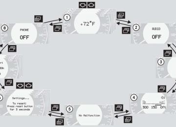
Warning indicators Visual signals indicate to the driver the rel- ative distance between the sensors and an obstacle. The warning indicator for the front area is located above the center air vents in the dashboard. The warning indi- cator for the rear area is integrated in the rear trim.
Each warning indicator is divided into six yellow and two red segments for either side of the vehicle. The Parktronic system is ready when the border around the indi- cator is illuminated. The position of the gear selector lever de- termines which warning indicators will be activated.
앫 Front area: An intermittent acoustic
warning will sound as the first red seg- ment comes on and a constant acous- tic warning lasting a maximum of three seconds will sound for the sec- ond red segment. The signal is can- celed when the selector lever is placed in position P and the parking brake is activated.
Warning indicator
앫 Rear area: An intermittent acoustic
Selector lever po- sition R or N
Front area activated Front and rear area activated Neither activated
Front area warning indicator 1 Left side of the vehicle 2 Right side of the vehicle
As your vehicle approaches an object, one or more segments will come on, depending on the distance. When the eighth segment comes on, you have reached the minimum distance.
warning will sound as the first red seg- ment comes on and a constant acous- tic warning lasting a maximum of three seconds will sound for the sec- ond red segment. The signal is can- celed when the selector lever is placed in position D or P and the parking brake is activated.
231
Controls in detail Driving systems
Switching the Parktronic system on/off You can switch off the Parktronic system manually. The Parktronic system switch is located in the lower section of the center console.
1 Parktronic system on/off 2 Indicator lamp
232
Switching off the Parktronic system 왘 Press button 1.
Indicator lamp 2 comes on.
Switching on the Parktronic system 왘 Press button 1 again.
Indicator lamp 2 goes out.
Parktronic system malfunction There is a malfunction in the Parktronic system if the red segments of the Parktronic system warning indicator come on and a warning sounds. The Parktronic system will switch itself off after 30 seconds and the indicator lamp on the Parktronic system switch comes on. 왘 Have the Parktronic system checked by an authorized Mercedes-Benz Cen- ter as soon as possible.
If only the red segments of the Parktronic system warning indicator come on and no warning sounds, then the sensors of the Parktronic system are dirty or malfunction- ing. Malfunction may also be caused by in- terference from other radio or ultrasonic signals. The Parktronic system will switch itself off after 20 seconds. 왘 Clean Parktronic system sensors
(컄 page 305).
왘 Switch on the ignition.
or
왘 Check Parktronic system operation at
another location to rule out interfer- ence from outside radio or ultrasonic signals.
Controls in detail Loading
Preparing roof rack installation 왘 Open trim 1 at the trim strips in the
roof.
왘 Secure the roof rack according to man- ufacturer’s instructions for installation.
Ski sack*
Load the roof rack in such a way that the vehicle cannot be damaged while driving. Make sure 앫 you can fully raise the
sliding/pop-up roof* or panorama sliding/pop-up roof*
앫 you can fully open the trunk
Unfolding and loading 왘 Fold armrest down (arrow). 왘 Swing cover 1 down.
컄컄
왔 Loading Roof rack*
Warning!
Use only roof racks approved by Mercedes-Benz for your vehicle model to avoid damage to the vehicle. Follow manu- facturer’s installation instructions.
1 Trim
233
Controls in detail Loading
컄컄
왘 Open hook and loop strap 1. 왘 Pull ski sack into passenger compart-
ment and unfold.
왘 From trunk, slide skis into ski sack.
왘 Wrap strap around ski sack and arm-
Warning!
rest.
왘 Close clasp (arrows) and pull strap
tight to firmly secure skis.
The ski sack is designed for up to four pairs of skis. Do not load the ski sack with other objects.
Always fasten the ski sack securely. In an accident, an unfastened ski sack can cause injury to vehicle occupants.
234
Controls in detail Loading
Unloading and folding
왘 Connect snap hook 1 of front strap to
eye 2 located on center tunnel in front of rear seat bench.
왘 Loosen strap, open clasp by pressing
tabs together (arrows).
왘 Unload skis. 왘 Close flap in trunk. 왘 Fold and flatten ski sack lengthwise
and place folded ski sack inside recess of backrest.
왘 Close ski sack compartment cover.
235
Controls in detail Loading
Removal of ski sack For removal of the ski sack we recommend that you contact an authorized Mercedes-Benz Center.
Warning!
Never drive vehicle with trunk open while the ski sack is removed. Deadly carbon monoxide (CO) gases may enter vehicle in- terior, resulting in unconsciousness and death.
To prevent unauthorized persons from access to the trunk, always close the cover.
236
Split rear bench seat*
Folding the backrest forward
To expand the trunk, you can fold down the left and right rear seat backrests. The two sections can be folded down sep- arately to enlarge the trunk.
Warning!
When expanding the luggage compartment, always fold the seat cushions fully forward.
Unless you are transporting cargo, the back- rests must remain properly locked in the up- right position.
In an accident, during hard braking or sud- den maneuvers, loose items will be thrown around inside the vehicle, and cause injury to vehicle occupants unless the items are securely fastened in the vehicle.
Always use the cargo tie down rings (컄 page 241).
You must always release the seat cush- ion and fold it up before folding the seat backrests forward. The upholstery on the seat backrest may otherwise be damaged.
1 Release handle
Controls in detail Loading
If tall persons have occupied the driv- er’s and front passenger seats, it may be necessary to move these seats for- ward slightly in order to fold the rear seat backrests forward.
왘 Pull release handle 1.
The seat cushion automatically springs upward slightly.
왘 Grip the back of seat cushion 1 and
fold forward.
왘 Push the rear seat head restraints all
the way in.
왘 Pull the handle in the trunk.
The seat backrest is released and the head restraints fold back.
왘 Fold the seat backrest forward.
If the rear center seat is to be occupied while driving, it may be necessary to fold the seat belt buckle up again.
Make sure the head restraints fit all the way into the seat cushion pockets. This will prevent the backrests from being damaged during loading.
1 Seat cushion 2 Seat backrest
237
왘 Swing the head restraint forward by
hand until it engages.
Warning!
Always lock backrest in its upright position when rear seat bench is occupied, or the ex- tended trunk compartment is not in use. Check for secure locking by pushing and pulling on the backrest.
In an accident, during hard braking or sud- den maneuvers, loose items will be thrown around inside the vehicle, and cause injury to vehicle occupants unless the items are securely fastened in the vehicle.
To help avoid personal injury during a colli- sion or sudden maneuver, exercise care when transporting cargo.
Controls in detail Loading
Returning seat backrest to original po- sition
1 Seat cushion 2 Seat backrest 왘 Swing seat backrest 2 to the rear until
it engages.
왘 Swing seat cushion 1 to the rear and press the center front of the cushion until it audibly engages.
238
Controls in detail Loading
왘 Press head restraint release catch 1 and pull the head restraints out of the guides.
왘 Fold the backrest into the vertical posi-
tion.
Leave the seat cushion hinge in this po- sition. The upholstery could be dam- aged if you fold the hinge back.
Expanding the cargo area*
Removing the rear seat cushions will pro- vide you with a larger, flat cargo area. 왘 Fold the seat cushions and the back-
rests forward.
왘 Remove the head restraints.
(Raise the seat backrest and fold the head restraints forward.)
1 Release lever 왘 Pull seat cushion release lever 1 and remove the seat cushion by pulling it upward.
왘 Fold the seat backrest forward.
1 Release catch
239
Controls in detail Loading
Loading instructions
The total load weight including vehicle oc- cupants and luggage/cargo should not ex- ceed the vehicle capacity weight indicated on the certification tag which can be found on the left door pillar.
240
The handling characteristics of a fully load- ed vehicle depend greatly on the load dis- tribution. It is therefore recommended to load the vehicle according to the illustra- tions shown, with the heaviest items being placed towards the front of the vehicle. Always place items being carried against front or rear seat backrests, and fasten them as securely as possible. The heaviest portion of the cargo should al- ways be kept as low as possible since it in- fluences the handling characteristics of the vehicle.
Warning!
Always fasten items being carried as secure- ly as possible.
In an accident, during hard braking or sud- den maneuvers, loose items will be thrown around inside the vehicle and can cause in- jury to vehicle occupants unless the items are securely fastened in the vehicle.
To help avoid personal injury during a colli- sion or sudden maneuver, exercise care when transporting cargo. Put luggage or car- go in the trunk if possible. Do not pile lug- gage or cargo higher than the seat backs. Do not place anything on the rear-window shelf.
Never drive vehicle with trunk open. Deadly carbon monoxide (CO) gases may enter ve- hicle interior resulting in unconsciousness and death.
Cargo tie-down rings*
Rear seat There is a cargo tie-down ring located on each side of the footwell under the rear seat.
Controls in detail Loading
Four rings 1 are located in the trunk. 왘 Carefully secure cargo by applying
even load on all rings with rope of suffi- cient strength to hold down the cargo. Always follow loading instructions (컄 page 240).
241
Controls in detail Useful features 왔 Useful features Interior storage spaces
Warning!
To help avoid personal injury during a colli- sion or sudden maneuver, exercise care when stowing objects in the vehicle. Put lug- gage or cargo in the trunk if possible. Do not pile luggage or cargo higher than the seat backs. Do not place anything on the shelf below the rear window.
Luggage nets cannot secure hard or heavy objects.
Keep compartment lids closed. This will help to prevent stored objects from being thrown about and injuring vehicle occupants during an accident.
242
Parcel net in front passenger footwell
Glove box
A small convenience parcel net is located in the front passenger footwell. It is for small and light items, such as road maps, mail, etc.
1 Glove box lid release 2 Compartment for mobile
phone/glasses
Warning!
Opening the glove box 왘 Push lid release 1.
The parcel net is intended for storing light-weight items only.
Heavy objects, objects with sharp edges or fragile objects may not be transported in the parcel net.
The parcel net cannot protect transported goods in the event of an accident.
The glove box lid opens downward.
Closing the glove box 왘 Push lid up to close.
i Prior to closing the glove box, close the compartment for glasses first.
Storage compartment in the center console (no CD changer* installed)
왘 Press button 1 to open.
The control panel swings out upward and the storage compartment extends out.
Never place any medications in the storage compartment. If there is a pow- er failure, the storage compartment cannot be opened.
왘 Press button 1 to close.
Cup holder in the center console
1 Opening/closing button
Controls in detail Useful features
왘 Briefly press the marking in the back of
the cover. The cover opens.
왘 Briefly press marking on the cup hold-
er. The cup holder extends automatically.
The cup holder can be removed for cleaning. Clean the cup holder only with clear, lukewarm water. Make sure to insert the cup holder in the guides when reinstalling it.
컄컄
243
Controls in detail Useful features
컄컄
Storage space under armrest
Front center console storage compart- ment ventilation The front center console storage compart- ment under the armrest has its own air vent. The air temperature is about the same as that of the dashboard air vents. The lever is located in the front center vent.
1 Left cup holder 2 Right cup holder
Warning!
When not in use, keep the cup holder closed while traveling. Place only containers that fit into the cup holder to prevent spills. Use lids on open containers and do not fill containers to a height where the contents, especially hot liquids, could spill during vehicle maneu- vers.
1 Storage compartment 2 Storage tray
Opening storage tray 왘 Pull handle 2.
Opening storage compartment 왘 Pull handle 1.
1 Lever
244
왘 To open air vent slide the lever up. 왘 To close air vent slide the lever down.
Storage compartment in the rear cen- ter console
Ruffled storage bags
Controls in detail Useful features
The compartment can get very warm due to its confined space. When storing heat sensitive objects (e.g. groceries) in the compartment, close the air vent while heating the passenger compart- ment
왘 Briefly press the top of the compart-
ment. It extends automatically.
Ruffled storage bags are located on the back of the front seats.
Warning!
The ruffled storage bag is intended for stor- ing light-weight items only.
Heavy objects, objects with sharp edges or fragile objects may not be transported in the ruffled storage bag.
The ruffled storage bag cannot protect transported goods in the event of an acci- dent.
245
Controls in detail Useful features
Storage compartment in the rear arm- rest
Rear cup holder
Ashtrays
Center console ashtray
왘 Press the handle upward and fold the
armrest up.
왘 Briefly press the front of the center
armrest. The cup holder extends automatically.
Warning!
When not in use, keep the cup holder closed while traveling. Place only containers that fit into the cup holder to prevent spills. Use lids on open containers and do not fill containers to a height where the contents, especially hot liquids, could spill during vehicle maneu- vers.
Opening ashtray 왘 Briefly press the marking on the bot-
tom of cover 1. The ashtray opens automatically.
A small rubber mat is located in the glove box. If you wish to store coins/tokens, remove the ashtray in- sert and insert the rubber mat in its place. Empty ashtray insert and store
246
it in a convenient location in the vehi- cle.
Warning!
Only use rubber mat in conjunction with storing coins/tokens. Always remove rub- ber mat and/or all other contents and rein- sert ashtray insert before placing hot cigarettes or other hot smoking materials in this compartment.
Removing ashtray insert
왘 Secure vehicle from movement by set- ting the parking brake. Move the gear selector lever to position N. Now you have more room to take out the insert.
왘 Push sliding button 2 to the right and
hold.
왘 Grip and remove insert from ashtray
frame.
Reinstalling ashtray insert 왘 Install insert by pushing it back into
frame until it engages again.
Warning!
Rear seat ashtray
Remove front ashtray only with vehicle standing still. Set the parking brake to se- cure vehicle from movement. Move gear se- lector lever to position N. With gear selector lever in position N, turn off the engine.
Controls in detail Useful features
Opening rear seat ashtray 왘 Briefly press the top of the ashtray.
The ashtray opens.
Cigarette lighter
The cigarette lighter is located in the cen- ter console compartment in front of the armrest (컄 page 26).
1 Cigarette lighter 왘 Turn ignition on. 왘 Push in cigarette lighter 1.
The lighter will pop out automatically when hot.
247
Controls in detail Useful features
Warning!
12-V socket*
Never touch the heating element or sides of the lighter; they are extremely hot. Hold the knob only.
When leaving the vehicle, always remove the SmartKey from the starter switch, take the SmartKey with KEYLESS-GO* with you, and lock your vehicle. Do not leave children un- attended in the vehicle, or with access to an unlocked vehicle. Unsupervised use of vehi- cle equipment may cause an accident and/or serious personal injury.
The lighter socket can be used to ac- commodate electrical accessories up to a maximum 85 W.
248
Heated steering wheel*
The steering wheel heating warms up the leather area of the steering wheel. The stalk with the heated steering wheel switch is on the lower left-hand side of the steering wheel.
The socket is located in the rear of the cen- ter console storage compartment. The socket can be used for accessories up to a maximum of 180 W.
1 Indicator lamp 2 Switching off 3 Switching on
Switching on 왘 Switch on ignition.
Telephone*
All lamps in the instrument cluster come on.
Warning!
왘 Turn switch at the tip of stalk in the di-
rection of arrow 3. The steering wheel is heated. Indicator lamp 1 comes on.
Switching off 왘 Turn switch at the tip of stalk in direc-
tion of arrow 2. The heated steering wheel is turned off. Indicator lamp 1 goes out.
The steering wheel heating does not turn off automatically.
Never operate radio transmitters equipped with a built-in or attached antenna (i.e. with- out being connected to an external antenna) from inside the vehicle while the engine is running. Doing so could lead to a malfunc- tion of the vehicle’s electronic system, pos- sibly resulting in an accident and/or serious personal injury.
Radio transmitters, such as a portable tele- phone or a citizens band unit, should only be used inside the vehicle if they are con- nected to an antenna that is installed on the outside of the vehicle. The external antenna must be approved by Mercedes-Benz. Please contact an autho- rized Mercedes-Benz Center for informa- tion on the installation of an approved external antenna. Refer to the radio trans- mitter operation instructions regarding use of an external antenna.
Controls in detail Useful features
Warning!
Please do not forget that your primary re- sponsibility is to drive the vehicle. A driver’s attention to the road must always be his /her primary focus when driving. For your safety and the safety of others, we rec- ommend that you pull over to a safe location and stop before placing or taking a tele- phone call. If you choose to use the telephone1 while driving, please use the hands-free device and only use the telephone when road, weather and traffic conditions permit. Some jurisdictions prohibit the driver from using a cellular telephone while driving a vehicle.
Only operate the COMAND (Cockpit Man- agement and Data System)
if road, weather and traffic conditions per- mit.
컄컄
1 Observe all legal requirements.
249
Controls in detail Useful features
컄컄
Bear in mind that at a speed of just 30 mph (approximately 50 km/h), your vehicle is covering a distance of approximately 44 feet (approximately 13.5 m) every sec- ond.
You can take and place telephone calls us- ing the s and t buttons on the steering wheel. To carry out other tele- phone functions, use the control system (컄 page 129). See separate operating manual for instruc- tions on how to use the telephone.
Warning!
Some jurisdictions prohibit the driver from using a cellular telephone while driving a ve- hicle. Whether or not prohibited by law, for safety reasons, the driver should not use the cellular telephone while the vehicle is in mo- tion.
Stop the vehicle in a safe location before an- swering or placing a call.
250
Tele Aid*
The initial activation of the Tele Aid sys- tem may only be performed by com- pleting the subscriber agreement and placing an acquaintance call using the SOS button. Failure to complete either of these steps will result in a system that is not activated. If the system is not activated, the indicator lamp in the SOS button stays on after turning the SmartKey in starter switch to position 2, or pressing the KEYLESS-GO* start/stop button twice to position 2. The message Tele Aid – not activated will be shown in the multifunction display for approximately 10 seconds. If you have any questions regarding ac- tivation, please call the Response Cen- ter at 1-800-756-9018 (in the USA) or 1-888-923-8367 (in Canada).
The Tele Aid system (Telematic Alarm Identification on De- mand) The Tele Aid system consists of three types of response: 앫 automatic and manual emergency 앫 roadside Assistance and 앫 information The Tele Aid system is operational provid- ing that the vehicle’s battery is charged, properly connected, not damaged and cel- lular and GPS coverage is available. The speaker volume of a Tele Aid call can be adjusted when using the volume control on the multifunction steering wheel. To raise, press button æ and to lower, press button ç. 왘 To activate, press the SOS button, the
Roadside Assistance button • or the Information button ¡, depend- ing on the type of response required.
i The SOS button is located above the in- terior rear view mirror. The Roadside Assistance button • and the Information button ¡ are located below the center armrest cov- er.
Shortly after the completion of your ac- quaintance call, you will receive a user ID and password via first call mail. By visiting www.mbusa.com and selecting “Tele Aid” (USA only), you will have access to account information, remote door unlock and more.
The Tele Aid system utilizes the cellular network for communication and the GPS (Global Positioning System) satel- lites for vehicle location. If either of these signals are unavailable, the Tele Aid system may not function and if this occurs, assistance must be sum- moned by other means.
System self-check Initially, after turning the ignition on, mal- functions are detected and indicated (the indicator lamps in the SOS button, the Roadside Assistance button • and the Information button ¡ stay on longer than ten seconds or do not come on). The message TELE AID – VISIT WORKSHOP! ap- pears for approximately 10 seconds in the multifunction display.
Controls in detail Useful features
Warning!
If the indicator lamps in the SOS button, in the Roadside Assistance button and/or in the Information button remain illuminated constantly in red and/or the message TELE AID - VISIT WORKSHOP! is displayed in the multifunction display after the system self-check, a malfunction in the system has been detected.
If a malfunction is indicated as outlined above, the system may not operate as ex- pected. Have the system checked at the nearest Mercedes-Benz Center as soon as possible.
251
tion display. All information relevant to the emergency, such as the location of the ve- hicle (determined by the GPS satellite loca- tion system), vehicle model, identification number and color are generated. A voice connection between the Response Center and the occupants of the vehicle will be established automatically soon af- ter the emergency call has been initiated. When a voice connection is established, the audio system mutes and the message TELE AID – EMERGENCY CALL ACTIVE ap- pears in the multifunction display. The Re- sponse Center will attempt to determine more precisely the nature of the accident provided they can speak to an occupant of the vehicle.
The Tele Aid system is available if: 앫 it has been activated and is operation- al. Activation requires a subscription for monitoring services, connection and cellular air time
앫 the relevant cellular phone network
and GPS signals are available and pass the information on to the response cen- ter
Location of the vehicle on a map is only possible if the vehicle is able to receive signals from the GPS satellite network and pass the information on to the re- sponse center.
Controls in detail Useful features
Emergency calls An emergency call is initiated automatical- ly: 앫 following an accident in which the
emergency tensioning devices (ETDs) or airbags deploy
앫 if the anti-theft alarm or the tow-away
alarm stays on for more than 20 seconds. See anti-theft alarm sys- tem (컄 page 84) and tow-away alarm (컄 page 85)
An emergency call can also be initiated manually by opening the cover next to the interior rear view mirror labeled SOS, then briefly pressing the button located under the cover. See below for instructions on initiating an emergency call manually. Once the emergency call is in progress, the indicator lamp in the SOS button will begin to flash. The message EMERGENCY CALL – CONNECTING CALL appears in the multifunc- tion display. When the connection is estab- lished, the message EMERGENCY CALL – CALL CONNECTED appears in the multifunc-
252
Warning!
Initiating an emergency call manually
Warning!
Controls in detail Useful features
If the indicator lamp in the SOS button is il- luminated continuously and there was no voice connection to the Response Center established, then the Tele Aid system could not initiate an emergency call (e.g. the rele- vant cellular phone network is not available). The message EMERGENCY CALL – CALL FAILED appears in the multifunction display for approximately 10 seconds.
Should this occur, assistance must be sum- moned by other means.
If you feel at any way in jeopardy when in the vehicle (e.g. smoke or fire in the vehicle, ve- hicle in a dangerous road location), please do not wait for voice contact after you have pressed the emergency button. Carefully leave the vehicle and move to a safe loca- tion. The Response Center will automatically contact local emergency officials with the vehicle’s approximate location if they re- ceive an automatic SOS signal and cannot make voice contact with the vehicle occu- pants.
253
1 Cover 2 SOS button 왘 Briefly press on cover 1.
The cover will open.
왘 Press SOS button 2 briefly.
The indicator lamp in SOS button 2 will flash until the emergency call is concluded.
왘 Wait for a voice connection to the Re-
sponse Center.
왘 Close cover after the emergency call is
concluded.
Controls in detail Useful features
Roadside Assistance button • Located below the center armrest cover is the Roadside Assistance button •. 왘 Press and hold the button (for longer
than 2 seconds). A call to a Mercedes-Benz Roadside As- sistance dispatcher will be initiated. The button will flash while the call is in progress. The message ROADSIDE AS- SISTANCE – CONNECTING CALL will ap- pear in the multifunction display.
When the connection is established, the message ROADSIDE ASSISTANCE – CALL CONNECTED appears in the multifunc- tion display. The Tele Aid system will trans- mit data generating the vehicle identification number, model, color and lo- cation (subject to availability of cellular and GPS signals). A voice connection between the Roadside Assistance dispatcher and the occupants of the vehicle will be established. When a voice connection is established, the audio system mutes and the message
TELE AID – ROADSIDE ASSISTANCE CALL ACTIVE appears in the multifunction display. 왘 Describe the nature of the need for as-
sistance.
The Mercedes-Benz Roadside Assistance dispatcher will either dispatch a qualified Mercedes-Benz technician or arrange to tow your vehicle to the nearest authorized Mercedes-Benz Center. For services such as labor and/or towing, charges may ap- ply. Refer to the Roadside Assistance man- ual for more information. These programs are only available in the USA: