- 2012 Mercedes-Benz CL Class Owners Manuals
- Mercedes-Benz CL Class Owners Manuals
- 2008 Mercedes-Benz CL Class Owners Manuals
- Mercedes-Benz CL Class Owners Manuals
- 2011 Mercedes-Benz CL Class Owners Manuals
- Mercedes-Benz CL Class Owners Manuals
- 2007 Mercedes-Benz CL Class Owners Manuals
- Mercedes-Benz CL Class Owners Manuals
- 2002 Mercedes-Benz CL Class Owners Manuals
- Mercedes-Benz CL Class Owners Manuals
- 2013 Mercedes-Benz CL Class Owners Manuals
- Mercedes-Benz CL Class Owners Manuals
- 2004 Mercedes-Benz CL Class Owners Manuals
- Mercedes-Benz CL Class Owners Manuals
- 2000 Mercedes-Benz CL Class Owners Manuals
- Mercedes-Benz CL Class Owners Manuals
- 2010 Mercedes-Benz CL Class Owners Manuals
- Mercedes-Benz CL Class Owners Manuals
- 2006 Mercedes-Benz CL Class Owners Manuals
- Mercedes-Benz CL Class Owners Manuals
- 2003 Mercedes-Benz CL Class Owners Manuals
- Mercedes-Benz CL Class Owners Manuals
- 2005 Mercedes-Benz CL Class Owners Manuals
- Mercedes-Benz CL Class Owners Manuals
- 2009 Mercedes-Benz CL Class Owners Manuals
- Mercedes-Benz CL Class Owners Manuals
- 2001 Mercedes-Benz CL Class Owners Manuals
- Mercedes-Benz CL Class Owners Manuals
- Download PDF Manual
-
3 Bulb socket for parking and standing
lamp
4 Bulb socket for turn signal lamp 5 Housing cover for Bi-Xenon headlamp
Practical hints Replacing bulbs
Replacing bulbs for front lamps
Before you start to replace a bulb for a front lamp, do the following first: 왘 Turn the exterior lamp switch to M
(컄 page 52).
왘 Open the hood (컄 page 273) (except
for side marker lamps).
1 Housing cover for high beam flasher
bulb, parking and standing lamp
376
Practical hints Replacing bulbs
High beam flasher bulb 왘 Press ends of housing cover 1 tab to-
gether and remove cover.
Parking and standing lamp bulb 왘 Press ends of housing cover 1 tab to-
gether and remove cover.
왘 Remove front end first. 왘 Twist bulb socket counterclockwise
and pull out.
왘 Press connector 2 downward. 왘 Remove connector 2 with the bulb. 왘 Insert the new bulb so that the base lo-
cates in the recess on the holder.
왘 From below, press connector 2 with
bulb upward onto the reflector.
왘 Align housing cover 1 and click into
place.
Front turn signal bulb 왘 Turn bulb socket 4 counterclockwise
and pull out.
왘 Gently push bulb into bulb socket 4,
turn counterclockwise and remove.
왘 Insert new bulb in bulb socket 4, push
in and twist clockwise.
왘 Reinsert bulb socket 4 in lamp and
twist clockwise.
왘 Pull out the bulb socket 3 with the
bulb.
왘 Pull the bulb out of the bulb socket 3. 왘 Insert a new bulb in the socket 3. 왘 Reinstall the bulb socket 3. 왘 Align housing cover 1 and click into
place.
왘 Pull bulb out of the bulb socket. 왘 Insert new bulb in socket. 왘 Reinstall bulb socket, push in and twist
clockwise.
왘 To reinstall lamp, set rear end in
bumper and let front end snap into place.
Side marker lamp bulb
Replacing bulbs for rear lamps
Before you start to replace a bulb for a front lamp, do the following first: 왘 Turn the exterior lamp switch to M
(컄 page 52).
왘 Open the trunk (컄 page 101).
왘 Carefully slide lamp towards rear.
377
Practical hints Replacing bulbs
Tail lamp assemblies
왘 Turn lock counterclockwise and move
License plate lamp
the trim to the side.
왘 Turn bulb socket counterclockwise and
pull out.
왘 Gently twist bulb counterclockwise and
pull out of bulb holder.
왘 Insert new bulb into the holder and turn
it clockwise.
왘 Reinstall bulb socket.
The bulb socket should audibly click.
왘 Replace trim and secure with lock.
1 Screws 왘 Loosen both screws 1. 왘 Remove the license plate lamp. 왘 Replace the bulb. 왘 Reinstall the license plate lamp. 왘 Retighten screws 1.
1 Black socket: Backup lamp 2 White socket:
Turn signal lamp
3 Red socket:
Tail, standing and parking lamp
4 Red socket:
Driver’s side: tail, parking and rear fog lamp Passenger’s side: tail and parking lamp
378
왔 Replacing wiper blades
To avoid damage to the hood, the wiper arms should only be folded forward when in the vertical position.
Wiper blades in vertical position
Removing wiper blades
왘 Turn SmartKey in starter switch to
position 1.
왘 Turn combination switch to wiper
setting II (컄 page 54).
왘 With wiper arm in vertical position, turn
SmartKey in starter switch to position 0.
Warning!
For safety reasons, switch off wipers and re- move SmartKey from starter switch (vehi- cles with KEYLESS-GO*: Make sure the vehicle's on-board electronics have status 0) before replacing a wiper blade. Other- wise, the wiper motor could suddenly turn on and cause injury.
왘 Fold the wiper arm forward until it
snaps into place.
Practical hints Replacing wiper blades
왘 Turn the wiper blade at a right angle to
wiper arm (arrow 1).
왘 Slide the wiper blade sideways out of
the retainer in the direction of arrow 2.
379
Practical hints Replacing wiper blades
Installing wiper blades
왘 Slide the wiper blade onto wiper arm
until it locks in place.
왘 Rotate the wiper blade into position
parallel to wiper arm.
왘 Fold the wiper arm backward to rest on
the windshield. Make sure you hold onto the wiper when folding the wiper arm back.
Never open the hood when the wiper arm is folded forward. Hold on to the wiper when folding the wiper arm back. If released, the force of the impact from the tensioning spring could crack the windshield. Do not allow the wiper arms to contact the windshield glass without a wiper blade inserted. Make certain that the wiper blades are properly installed. Improperly installed wiper blades may cause windshield damage. For your convenience, we recommend that you have this work carried out by an authorized Mercedes-Benz Center.
380
왔 Flat tire Preparing the vehicle
왘 Park the vehicle as far as possible from
moving traffic on a hard surface.
왘 Turn on the hazard warning flashers. 왘 Turn the steering wheel so that the front wheels are in a straight ahead position.
왘 Set the parking brake. 왘 Move the gear selector lever to P. Vehicles with SmartKey: 왘 Turn off the engine (컄 page 59). 왘 Remove the SmartKey from the starter
switch.
Vehicles with SmartKey with KEYLESS-GO*: 왘 Turn off the engine by pressing the KEYLESS-GO* button on the gear se- lector lever once (컄 page 59).
왘 Open the driver’s door (this puts the starter switch in position 0, same as with the SmartKey removed from the starter switch). The driver’s door then can be closed again.
Open door only when conditions are safe to do so.
왘 Have any passenger exit the vehicle at
a safe distance from the roadway.
Practical hints Flat tire
Mounting the spare wheel
Warning!
Never operate the vehicle with more than one spare wheel mounted.
The spare wheel rim is for temporary use only. Use for over a total of 12000 miles (20000 km) (aggregate of all uses) may cause wheel rim failure leading to an acci- dent and possible injuries.
The spare wheel should only be used tempo- rarily and replaced with a regular road wheel as quickly as possible.
CL 55 AMG, CL 65 AMG and Sport Pack- age* only: The spare wheel is for temporary use only. When driving with spare wheel mounted, en- sure proper tire inflation pressure and do not exceed vehicle speed of 50 mph (80 km/h).
컄컄
381
Practical hints Flat tire
컄컄
The dimensions of the spare wheel are dif- ferent from those of the road wheels. As a result, the vehicle handling characteristics change when driving with a mounted spare wheel. Adapt your driving style accordingly.
Preparing the vehicle 왘 Take vehicle tool kit tray and vehicle
jack out of trunk.
왘 Take the spare wheel out of wheel well
(컄 page 366).
Lifting the vehicle 왘 Prevent the vehicle from rolling away by blocking wheels with wheel chocks (not included) or other sizable objects.
When changing wheel on a level surface: 왘 Place one chock in front of and one be- hind the wheel that is diagonally oppo- site to the wheel being changed.
When changing wheel on a hill:
왘 Place chocks behind the downhill sides
of both wheels of the axle not being worked on.
Warning!
The jack is designed exclusively for jacking up the vehicle at the jack take-up brackets built into both sides of the vehicle. To help avoid personal injury, use the jack only to lift the vehicle during a wheel change. Never get beneath the vehicle while it is supported by the jack. Keep hands and feet away from the area under the lifted vehicle. Always firmly set parking brake and block wheels before raising vehicle with jack.
Do not disengage parking brake while the vehicle is raised. Be certain that the jack is always vertical (plumb line) when in use, es- pecially on hills. Always try to use the jack on level surface. Make sure the jack arm is fully seated in the jack take-up bracket. Al- ways lower the vehicle onto sufficient ca- pacity jackstands before working under the vehicle.
382
왘 Take the two-piece wheel wrench out of the vehicle tool kit tray. Assemble wheel wrench.
왘 On wheel to be changed, loosen but do
not yet remove the wheel bolts (ap- proximately one full turn with wrench). The tube openings are located directly be- hind the front wheel housings and in front of the rear wheel housings.
1 Jack support tube cover 왘 Move cover 1 toward rear by pressing
at point indicated by arrow.
왘 Remove cover 1 carefully to avoid
damage to the locking tabs.
1 Jack arm 2 Jack support tube hole 3 Crank 왘 Insert jack arm 1 fully into tube
hole 2 up to the stop.
Warning!
Insert the jack arm fully into the jack sup- port tube hole up to the stop. Otherwise the vehicle may fall from the jack and cause per- sonal injury or damage to the vehicle.
Practical hints Flat tire
왘 Keeping jack in this position, turn
crank 3 clockwise until the jack base meets the ground. Make sure the jack is vertical (plumb line).
왘 Continue to turn the crank until the tire is a maximum of 1.2 in (3 cm) from the ground.
Warning!
The jack is intended only for lifting the vehi- cle briefly for wheel changes. It is not suited for performing maintenance work under the vehicle. 앫 Never start the engine when the vehicle
is raised.
앫 Never lie down under the raised vehicle.
383
Practical hints Flat tire
Removing the wheel
1 Alignment bolt 왘 Unscrew upper-most wheel bolt and re-
move.
왘 Replace this wheel bolt with alignment
bolt 1 supplied in the tool kit.
왘 Remove the remaining bolts.
Do not place wheel bolts in sand or dirt. This could result in damage to the bolt and wheel hub threads.
왘 Remove the wheel.
384
Mounting the new wheel 왘 Clean contact surfaces of wheel and
wheel hub.
왘 Guide the spare wheel onto the align-
ment bolt and push it on.
왘 Insert wheel bolts and tighten them
To avoid paint damage, place wheel flat against hub and hold it there while in- stalling first wheel bolt.
Warning!
Always replace wheel bolts that are dam- aged or rusted.
Never apply oil or grease to wheel bolts.
Damaged wheel hub threads should be re- paired immediately. Do not continue to drive under these circumstances! Contact an au- thorized Mercedes-Benz Center or call Roadside Assistance.
Incorrect wheel bolts or improperly tight- ened wheel bolts can cause the wheel to come off. This could cause an accident. Make sure you are using the correct wheel bolts.
slightly.
왘 Unscrew the alignment bolt, install last
wheel bolt and tighten slightly.
Warning!
Use only genuine equipment Mercedes-Benz wheel bolts. Other wheel bolts may come loose.
Do not tighten the wheel bolts when the ve- hicle is raised. Otherwise the vehicle could tip over.
Lowering the vehicle 왘 Lower vehicle by turning crank coun-
terclockwise until vehicle is resting ful- ly on its own weight.
왘 Remove the jack.
왘 Before storing the jack in the trunk, it should be fully collapsed, with handle folded in.
왘 Place the wheel bolt wrench, alignment bolt and jack back in the vehicle tool kit in the trunk and close the covering lid.
Replacing jack support tube cover 왘 Slide tongue of cover under the upper
edge of the tube opening.
왘 Applying even pressure, press cover
until it snaps into place. Be careful not to damage the locking tabs or clamp the plastic retaining strap.
You can also screw the faulty wheel down into the spare wheel well in the trunk. Do not activate the tire inflation pres- sure monitor until the depressurized tire is no longer in the vehicle.
1 - 5 Wheel bolts 왘 Tighten the five wheel bolts evenly, fol- lowing the diagonal sequence illustrat- ed (1 to 5), until all bolts are tight. Observe a tightening torque of 110 lb-ft (150 Nm).
Warning!
Have the tightening torque checked after changing a wheel. The wheels could come loose if they are not tightened to a torque of 110 lb-ft (150 Nm).
Practical hints Flat tire
385
Practical hints Battery
Warning!
Failure to follow these instructions can re- sult in severe injury or death.
Never lean over batteries while connecting, you might get injured.
Battery fluid contains sulfuric acid. Do not allow this fluid to come in contact with eyes, skin or clothing. In case it does, immediately flush affected area with water and seek medical help if necessary.
A battery will also produce hydrogen gas, which is flammable and explosive. Keep flames or sparks away from battery, avoid improper connection of jumper cables, smoking, etc.
Warning!
Do not place metal objects on the battery as this could result in a short circuit.
Use leak-proof battery only to avoid the risk of acid burns in the event of an accident.
386
The battery is located in the trunk under the right hand wheel well cover panel.
1 Battery cover 2 Locking knob 왘 Rotate and loosen locking button 2
approx. one-half turn.
왘 Remove battery cover 1.
Never loosen or detach battery termi- nal clamps while the engine is running or the SmartKey is in the starter switch. Otherwise the alternator and other electronic components could be se- verely damaged. Have the battery checked regularly by an authorized Mercedes-Benz Center. Refer to Maintenance Booklet for main- tenance intervals or contact your au- thorized Mercedes-Benz Center for further information.
Warning!
With a disconnected battery 앫 you will no longer be able to turn the
SmartKey in the starter switch and pressing the KEYLESS-GO* start/stop button (컄 page 35) on the gear selector lever will have no effect
앫 the gear selector lever will remain
locked in position P
3 Negative terminal 4 Cover over positive terminal
Practical hints Battery
Disconnecting the battery
Charging and reinstalling the battery
왘 Turn off all electrical consumers. 왘 Open the trunk (컄 page 101). 왘 Use a 10 mm open-end wrench to dis- connect the battery negative lead 3. 왘 Remove cover 4 from the positive ter-
minal.
왘 Charge battery in accordance with the
instructions of the battery charger manufacturer.
왘 Reinstall the charged battery. Follow the previously described steps in re- verse order.
왘 Disconnect the battery positive lead.
Warning!
Removing the battery
왘 Remove the screw securing the bat-
tery.
왘 Remove the battery support and
bracket.
왘 Take out the battery.
Never charge a battery while still installed in the vehicle. Gases may escape during charg- ing and cause explosions that may result in paint damage, corrosion or personal injury.
387
Practical hints Battery
Reconnecting the battery
왘 Turn off all electrical consumers. 왘 Connect the positive lead and fasten its
cover 4.
왘 Connect negative lead 3.
Never invert the terminal connections.
The battery, its filler caps and the vent tube must always be securely installed when the vehicle is in operation.
The following procedures must be car- ried out following any interruption of battery power (e.g. due to reconnect- ing): 앫 Set the clock (see COMAND opera-
tor’s manual).
앫 Synchronize the ESP (컄 page 340). 앫 Synchronize side windows
(컄 page 200).
앫 Synchronize tilt/sliding sunroof
(컄 page 205).
Batteries contain materials that can harm the environment if disposed of improperly. Large 12-volt storage batteries contain lead. Recycling of batteries is the preferred method of disposal. Many states require sellers of batteries to accept old batteries for recycling.
388
왔 Jump starting
Warning!
Failure to follow these directions will cause damage to the electronic components, and can lead to a battery explosion and severe injury or death.
Never lean over batteries while connecting or jump starting, you might get injured.
Battery fluid contains sulfuric acid. Do not allow this fluid to come in contact with eyes, skin or clothing. In case it does, immediately flush affected area with water, and seek medical help if necessary.
A battery will also produce hydrogen gas, which is flammable and very explosive. Keep flames or sparks away from battery, avoid improper connection of jumper cables, smoking, etc.
Attempting to jump start a frozen battery can result in it exploding, causing personal injury.
Read all instructions before proceeding.
If the battery is discharged, the engine can be started with jumper cables and the bat- tery of another vehicle. Observe the follow- ing: 앫 Jump starting should only be performed when the engine and catalytic convert- er are cold.
앫 Do not start the engine if the battery is
frozen. Let the battery thaw out first. 앫 Only use 12 volt battery to jump start your vehicle. Jump starting with a more powerful battery could damage the ve- hicle’s electrical system, which will not be covered by the Mercedes-Benz Lim- ited Warranty.
앫 Only use jumper cables with sufficient
cross-section and insulated terminal clamps.
앫 Always make sure that the jumper ca- bles are not on or near pulleys, fans or other parts that move when an engine is started or running.
Practical hints Jump starting
Avoid repeated and lengthy starting at- tempts. Do not attempt to start the engine us- ing a battery quick charge unit. If engine does not run after several un- successful starting attempts, have it checked at the nearest authorized Mercedes-Benz Center. Excessive unburned fuel generated by repeated failed starting attempts may damage the catalytic converter and may present a fire risk. Make sure the jumper cables do not have loose or missing insulation. Make sure the cable clamps do not touch any other metal part while the other end is still attached to a battery.
Do not tow-start the vehicle.
389
Practical hints Jump starting
Warning!
Keep flames or sparks away from battery. Do not smoke.
Observe all safety instructions and precau- tions when handling automotive batteries (컄 page 281).
The battery is located on the right side of the trunk under the battery cover (컄 page 386). 왘 Make sure the two vehicles do not
touch.
왘 Turn off all electrical consumers. 왘 Apply parking brake. 왘 Shift gear selector lever to position P. 왘 Open the trunk lid. 왘 Remove battery cover. 왘 Remove red cover from positive
terminal 1.
390
Never invert the terminal connections.
왘 Start engine of the vehicle with the
charged battery and run at idle speed. 왘 Connect negative terminals 2 and 4 of the batteries with the jumper cable. Clamp cable to charged battery 4 first.
왘 Start the engine of the disabled vehi-
cle.
Now you can again turn on the electrical consumers. Do not turn on the lights under any circumstances. 왘 Remove the jumper cables first from
negative terminals 2 and 4 and then from positive terminals 1 and 3.
You can now turn on the lights. 왘 Have the battery checked at the near- est authorized Mercedes-Benz Center.
1 Positive terminal of discharged battery 2 Negative terminal of discharged bat-
tery
3 Positive terminal of charged battery 4 Negative terminal of charged battery 왘 Connect positive terminals 1 and 3 of the batteries with the jumper cable. Clamp cable to charged battery 3 first.
When circumstances do not permit the recommended towing methods, the vehi- cle may be towed with all wheels on the ground or front wheels raised only so far as necessary to have the vehicle moved to a safe location where the recommended towing methods can be employed.
왔 Towing the vehicle Mercedes-Benz recommends that the vehi- cle be transported with all wheels off the ground using flatbed or appropriate wheel lift/dolly equipment. This method is pref- erable to other types of towing.
Use flatbed or wheel lift/dolly equip- ment with SmartKey in starter switch turned to position 0. Do not tow with sling-type equipment. Towing with sling-type equipment over bumpy roads will damage radiator and supports. To prevent damage during transport, do not tie down vehicle by its chassis or suspension parts. Switch off the tow-away alarm (컄 page 87) and the automatic central locking (컄 page 162). Do not tow-start the vehicle.
Practical hints Towing the vehicle
If the vehicle is towed with the front axle raised, the engine must be shut off (SmartKey in starter switch position 0 or 1). Otherwise, the ESP will immedi- ately be engaged and will apply the rear wheel brakes. When towing the vehicle with all wheels on the ground, the selector lever must be in position N and the SmartKey must be in starter switch position 2. When towing the vehicle with all wheels on the ground or the front axle raised, the vehicle may be towed only for dis- tances up to 30 miles (50 km) and at a speed not to exceed 30 mph (50 km/h).
391
i To signal turns while being towed with the hazard warning flasher in use, turn SmartKey in starter switch to position 2 and activate the combina- tion switch for the left or right turn sig- nal in the usual manner – only the selected turn signal will operate. Upon canceling the turn signal, the haz- ard warning flasher will operate again.
Practical hints Towing the vehicle
To be certain to avoid a possibility of damage to the drive train, however, we recommend the drive shaft be discon- nected at the rear axle drive flange for any towing beyond a short tow to a nearby garage.
If the SmartKey is left in starter switch posi- tion 0 for an extended period of time, it can no longer be turned in the switch. In this case, the steering is locked. To unlock, re- move SmartKey from starter switch and re- insert.
Warning!
Warning!
If circumstances require towing the vehicle with all wheels on the ground, always tow with a tow bar if: 앫 the engine will not run 앫 there is a malfunction in the power sup- ply or in the vehicle’s electrical system as that will be necessary to adequately con- trol the towed vehicle.
Prior to towing the vehicle with all wheels on the ground, make certain that the SmartKey is in starter switch position 2.
392
With the engine not running, there is no power assistance for the brake and steering systems. In this case, it is important to keep in mind that a considerably higher degree of effort is necessary to brake and steer the ve- hicle. Adapt your driving accordingly.
The gear selector lever will remain locked in position P and the SmartKey will not turn in the starter switch if the battery is disconnected or discharged. See information on the battery (컄 page 386) or on jump starting (컄 page 389).
! When towing the vehicle with all wheels on the ground, please note the follow- ing: With the automatic central locking acti- vated and the SmartKey in starter switch position 2, or KEYLESS-GO* start/stop button (컄 page 35) in position 2, the vehicle doors lock if the left front wheel as well as the right rear wheel are turning at vehicle speeds of approx. 9 mph (15 km/h) or more. Switch off the tow-away alarm (컄 page 87). To prevent the vehicle door locks from locking, deactivate the automatic cen- tral locking (컄 page 162). Towing of the vehicle should only be done using the properly installed tow- ing eye bolt. Never attach tow cable, tow rope or tow rod to the vehicle chas- sis, frame or suspension parts.
Installing towing eye bolt
1 Cover on right side of front bumper
Practical hints Towing the vehicle
Removing cover 왘 Press mark on cover in direction of ar-
row.
왘 Lift cover off to reveal threaded hole for
towing eye bolt.
Installing towing eye bolt 왘 Take towing eye bolt and wheel wrench
out of trunk (컄 page 365).
왘 Screw towing eye bolt clockwise into its stop and tighten with wheel wrench.
Removing towing eye bolt 왘 Loosen towing eye bolt counterclock-
wise with wheel wrench. 왘 Unscrew towing eye bolt. 왘 Store towing eye bolt and wheel
wrench in trunk.
2 Cover on right side of rear bumper
Installing cover 왘 Fit cover and snap into place.
393
! Never attempt to repair or bridge a blown fuse. Have the cause determined and remedied by an authorized Mercedes-Benz Center.
Your vehicle’s electrical fuses are located in various fuse boxes: 앫 In the dashboard on the passenger side
(컄 page 395)
앫 In the rear passenger compartment un-
der the right rear seat (컄 page 395)
앫 In the engine compartment on the driv-
er’s side (컄 page 396)
앫 In the engine compartment on the pas-
senger side (컄 page 396)
Aids for replacing fuses
Fuse chart A chart explaining fuse allocation and fuse amperages can be found in the vehicle tool kit in the trunk (컄 page 365).
Spare Fuses Spare Fuses are found in the vehicle tool kit in the trunk (컄 page 365).
Fuse extractor The fuse extractor is found in the vehicle tool kit in the trunk (컄 page 365).
Practical hints Fuses
Fuses are designed to protect the electri- cal circuits in your vehicle from a short cir- cuit. If a fuse is blown, the component(s) and systems controlled by that fuse will stop working. The following aids are available to help you replace fuses (컄 page 394): 앫 Fuse chart. 앫 Spare fuses 앫 Special fuse extractor
Warning!
Only use fuses approved by Mercedes-Benz and which have the specified amperage. Us- ing other fuses may cause an overload and lead to a fire, or cause damage to electrical components and/or systems.
394
Fuse boxes in passenger compartment
There are two fuse boxes. One fuse box is located in the dashboard on the front pas- senger side. An additional fuse box is lo- cated under the right rear seat.
Fuse box in dashboard
1 Cover
Do not use sharp objects such as a screw driver to open the fuse box cover 2 in the dashboard, as this could damage it.
Opening 왘 Open the front passenger door. 왘 Using the flat of your hand, press on
the middle of the cover 1. The edge of cover 1 lifts up slightly from the dashboard.
왘 Insert flat, blunt object into the edge of
the cover as a lever.
왘 Loosen cover 1 from the dashboard
using lever.
왘 Using your hands, pull cover 1 in the
direction of the arrow and remove.
Closing 왘 Hook cover 2 into the opening at the
front.
왘 Press cover 2 back on until it engag-
es.
Practical hints Fuses
Fuse box in the rear passenger compartment
1 Cover
Opening 왘 Pull cover 1 away from fuse box in di-
rection of arrow.
왘 Remove cover rearward.
Closing 왘 Press cover back on until it engages.
395
Closing 왘 Replace cover 1 and press it down by
hand.
왘 Push both slides 2 to the ‹ sym-
bol.
The cover must fit properly and the slide must be positioned at the ‹ symbol, as moisture or dirt may impair the functionality of the fuses.
1 Fuse box cover, front passenger side 2 Slide
Opening 왘 Push both slides 2 to the Œ sym-
bol.
왘 Remove cover 1.
Practical hints Fuses
Fuse boxes in engine compartment
There are fuse boxes located in the engine compartment on the driver’s and front pas- senger side in front of the firewall (dividing wall between engine compartment and passenger compartment).
1 Fuse box cover, driver’s side 2 Slide
396
Technical data Parts service
Warranty coverage
Identification labels
Layout of poly-V-belt drive
Engine
Rims and Tires
Electrical system
Main Dimensions and weights
Fuels, coolants, lubricants, etc.
397
Technical data Parts service
The “Technical data” section provides the necessary technical data for your vehicle.
The use of non-genuine Mercedes-Benz parts and accessories not authorized by Mercedes-Benz could damage the vehicle, which is not covered by the Mercedes-Benz Limited Warranty, or could compromise the vehicle’s dura- bility or safety.
All authorized Mercedes-Benz Centers maintain a stock of genuine Mercedes-Benz parts required for mainte- nance and repair work. In addition, strate- gically located parts distribution centers provide quick and reliable parts service. More than 300 000 different parts for Mer- cedes-Benz models are available. Genuine Mercedes-Benz parts are subject- ed to stringent quality inspections. Each part has been specifically developed, man- ufactured or selected for and adapted to Mercedes-Benz vehicles. Therefore, genuine Mercedes-Benz parts should be installed.
398
Technical data Warranty coverage
Replacement parts and accessories are covered by the Mercedes-Benz Parts and Accessories warranties, copies of which are available at any Mercedes-Benz Cen- ter.
Loss of Service and Warranty Information Booklet
Should you lose your Service and Warranty Information booklet, have an authorized Mercedes-Benz Center arrange for a re- placement. It will be mailed to you.
왔 Warranty coverage Your vehicle is covered under the terms of the warranties printed in the Service and Warranty Information booklet. Your authorized Mercedes-Benz Center will ex- change or repair any defective parts origi- nally installed in the vehicle in accordance with the terms of the following warranties: 앫 New Vehicle Limited Warranty 앫 Emission System Warranty 앫 Emission Performance Warranty 앫 California, Maine, Massachusetts, and
Vermont Emission Control Systems Warranty
399
Technical data Identification labels
1 Certification label (on driver’s B pillar)
2 Vehicle Identification Number (VIN)
(below right rear passenger seat)
3 Engine number (engraved on engine) 4 VIN, visible (lower edge of windshield) 5 Emission control information label, includes both federal and California certification exhaust emission standards
6 Vacuum line routing diagram label When ordering parts, please specify vehi- cle identification and engine numbers.
400
왔 Layout of poly-V-belt drive CL 500
Technical data Layout of poly-V-belt drive
CL 55 AMG
CL 600 and CL 65 AMG
1 Automatic belt tensioner 2 ABC tandem pump (pump for
power-steering assistance and ABC chassis)
3 Air conditioning compressor 4 Crankshaft 5 Coolant pump 6 Generator (alternator) 7 Idler pulley
The CL 55 AMG has two poly-V-belts (belt one shown in purple/belt two shown in black). 1 Idler pulley 2 Automatic belt tensioner 3 ABC tandem pump (pump for
power-steering assistance and ABC chassis)
4 Air conditioning compressor 5 Crankshaft 6 Coolant pump 7 Generator (alternator) 8 Idler pulley 9 Automatic belt tensioner a Supercharger
1 Automatic belt tensioner 2 ABC tandem pump (pump for
power-steering assistance and ABC chassis)
3 Air conditioning compressor 4 Crankshaft 5 Coolant pump 6 Generator (alternator) 7 Idler pulley 8 Idler pulley 9 Idler pulley
401
Technical data Engine
Model Engine Mode of operation No. of cylinders Bore Stroke Total piston displacement Compression ratio Output acc. to SAE J 1349
Maximum torque acc. to SAE J 1349
Maximum engine speed Firing order Poly-V-beltCL 500 (215.375)1
113
4-stroke engine, gasoline injection 3.82 in (97.00 mm) 3.31 in (84.00 mm) 303.0 cu in (4966 cm3) 10:1
302 hp/5600 rpm 2 (225 kW/5600 rpm) 339 lb-ft/2700 - 4250 rpm (460 Nm/2700 - 4250 rpm) 6000 rpm 1-5-4-2-6-3-7-8
2380 mmCL 55 AMG (215.374)1
113
4-stroke engine, gasoline injection 3.82 in (97.00 mm) 3.60 in (92.00 mm) 331.8 cu in (5439 cm3) 9:1
493 hp/6100 rpm2
(368 kW/6100 rpm) 516 lb-ft/2750–4000 rpm (700 Nm/2750–4000 rpm) 6500 rpm 1-5-4-2-6-3-7-8
Belt one: 1289 mm Belt two: 2462 mm1 The quoted data apply only to the standard vehicle. See an authorized Mercedes-Benz Center for the corresponding data of all special bodies and special equipment. 2 Premium fuel required. Performance may vary with fuel octane rating.
402
Technical data Engine
Model Engine Mode of operation No. of cylinders Bore Stroke Total piston displacement Compression ratio Output acc. to SAE J 1349
CL 600 (215.376)1
275
4-stroke engine, gasoline injection 12
3.23 in (82.00 mm) 3.43 in (87.00 mm) 336.4 cu in (5513 cm3) 9:1
493 hp/5000 rpm2 (368 kW/5000 rpm) 590 lb-ft/1800–3500 rpm (800 Nm/1800–3500 rpm) 5950 rpm 1-12-5-8-3-10-6-7-2-11-4-9
2335 mmCL 65 AMG (215.379)1
275
4-stroke engine, gasoline injection 12
3.25 in (82.60 mm) 3.66 in (93.00 mm) 364.9 cu in (5980 cm3) 9:1
603 hp/4800 - 5100 rpm 2 (450 kW/4800 - 5100 rpm) 738 lb-ft/2000 - 4000 rpm (1000 Nm/2000 - 4000 rpm) 5950 rpm 1-12-5-8-3-10-6-7-2-11-4-9
2335 mmMaximum torque acc. to SAE J 1349
Maximum engine speed Firing order Poly-V-belt 1 The quoted data apply only to the standard vehicle. See an authorized Mercedes-Benz Center for the corresponding data of all special bodies and special equipment. 2 Premium fuel required. Performance may vary with fuel octane rating.403
Technical data Rims and Tires
Use only tires and rims which have been specifically developed for your vehicle and tested and approved by Mercedes-Benz. Other tires and rims can have detrimental effects, such as 앫 Poor handling characteristics 앫 Increased noise 앫 Increased fuel consumption
Moreover, tires and rims not approved by Mercedes-Benz may, under load, ex- hibit dimensional variations and differ- ent tire deformation characteristics that could cause them to come into contact with the vehicle body or axle parts. Damage to the tires or the vehi- cle may be the result.
Further information on tires and rims is available at any authorized Mercedes-Benz Center. A placard with the recommended tire inflation pres- sures is located on the driver's door B-pillar. Some vehicles may have sup- plemental tire pressure information for driving at high speeds (컄 page 293) or for vehicle loads less than the maxi- mum loaded vehicle condition. If such information is provided, it can be found on the placard located on the inside of the fuel filler flap. The tire pressure should be checked regularly and should only be adjusted on cold tires. Follow tire manufacturer’s mainte- nance recommendation included with vehicle.
404
Technical data Rims and Tires
Same size tires
Rims (light alloy) Wheel offset Summer tires (radial-ply tires) All season tires (radial-ply tires) Winter tires (radial-ply tires)
CL 500 (except Sport Package* and except Appearance Package*) 71/2 J x 17 H2
1.81 in (46 mm) 225/55 R17 97H M+S 225/55 R17 97H M+SCL 600 (except Sport Package* and except Appearance Package*) 8 J x 18 H21
1.73 in (44 mm) 245/45 R18 96Y1
245/45 R18 100V XL M+S1
or 245/45 R18 96H M+S11 For use with snow chains contact an authorized Mercedes-Benz Center
405
Technical data Rims and Tires
CL 500, CL 600 (Appearance Package*) CL 500, CL 600 (Sport Package*)
Rims (light alloy)
8 J x 18 H21
Wheel offset Summer tires (radial-ply tires) All season tires (radial-ply tires) Winter tires (radial-ply tires)
1.73 in (44 mm) 245/45 R18 96Y1
245/45 R18 100V XL M+S1
or 245/45 R18 96H M+S11 For use with snow chains contact an authorized Mercedes-Benz Center 2 Must not be used with snow chains
CL 55 AMG 8 J x 18 H21
or 81/2 J x18 EH22
1.73 in (44 mm) 245/45 R18 100V XL M+S1 or 245/45 R18 96H M+S1406
Technical data Rims and Tires
Mixed size tires
Front axle
Rear axle
AMG light alloy rims Wheel offset Summer tires (radial-ply tires) 245/45 R18 100Y XL (Extra Load)1
CL 500, CL 600 (Sport Package*) CL 55 AMG 81/2 J x 18 EH21
1.73 in (44 mm)or 245/45 ZR18 100Y XL (Extra Load)1
9 J x 18 EH21
1.73 in (44 mm)AMG light alloy rims Wheel offset Summer tires (radial-ply tires) 265/40 R18 101Y XL (Extra Load)1
or 265/40 ZR18 101Y XL (Extra Load)1
CL 65 AMG
81/2 J x 19 H21
1.73 in (44 mm) 245/40 ZR19 98Y XL (Extra Load)1
or 245/40 ZR191
91/2 J x 19 H21
2.36 in (60 mm) 275/35 ZR19 100Y XL (Extra Load)1
or 275/35 ZR1911 Must not be used with snow chains
407
Technical data Rims and Tires
Spare wheel
Rims (light alloy) Wheel offset Summer tires (radial-ply tires)
CL 500 (except Sport Package* and except Appearance Package*) 7 1/2 J x 17 H2
2.0 in (51 mm)CL 600, CL 500 (Sport Package* and Appearance Package*) CL 55 AMG 8 J x 18 H2
1.73 in (44 mm) 245/45 ZR18 96YAll season tires (radial-ply tires) 225/55 R17 97H M+S
CL 65 AMG
8 J x 19 H2
1.97 in (50 mm) 245/40 ZR19 98Y XL (Extra Load)408
Technical data Electrical system
CL 55 AMG 14 V/180 A
CL 600
14 V/180 ACL 65 AMG 14 V/180 A
12 V/1.7 kW 12 V/95 Ah NGK ILFR 6 A
12 V/1.7 kW 12 V/95 Ah Bosch F 8 DPP332
NGK PFR 5 R-11
0.039 in (1.0 mm) 15 – 22 lb-ft (20 – 30 Nm) 18 – 22 lb-ft (25 – 30 Nm) 15 – 22 lb-ft (20 – 30 Nm) 15 – 22 lb-ft (20 – 30 Nm)12 V/1.7 kW 12 V/95 Ah NGK NFR 6Q G
12 V/1.7 kW 12 V/95 Ah NGK NFR 6Q G
0.028 in (0.7 mm)
0.028 in (0.7 mm)
0.031 in (0.8 mm)
CL 500
14 V/150 A왔 Electrical system Model Generator (alterna- tor) Starter motor Battery Spark plugs
Electrode gap Tightening torque
409
Technical data Main Dimensions and weights
Main Dimensions
Model Overall vehicle length Overall vehicle width Overall vehicle height Wheelbase Track, front Track, rear
CL 500
196.4 in (4989 mm) 73.1 in (1857 mm) 55.4 in (1408 mm) 113.6 in (2885 mm) 62.1 in (1577 mm) 62.1 in (1578 mm)CL 55 AMG 196.4 in (4989 mm) 73.1 in (1857 mm) 55.4 in (1408 mm) 113.6 in (2885 mm) 62.2 in (1581 mm) 62.2 in (1582 mm)
CL 600
196.4 in (4989 mm) 73.1 in (1857 mm) 55.4 in (1408 mm) 113.6 in (2885 mm) 62.1 in (1577 mm) 62.1 in (1578 mm))CL 65 AMG 196.4 in (4989 mm) 73.1 in (1857 mm) 55.4 in (1408 mm) 113.6 in (2885 mm) 62.2 in (1581 mm) 62.2 in (1582 mm)
Weights
Roof load max. Trunk load max.
220 lbs (100 kg) 220 lbs (100 kg)
410
왔 Fuels, coolants, lubricants, etc. Capacities
Technical data Fuels, coolants, lubricants, etc.
Vehicle components and their respective lubricants must match. Therefore use only brands tested and approved by us.
Please refer to the Factory Approved Ser- vice Products pamphlet, or inquire at your Mercedes-Benz Center.
Engine with oil filter
Automatic transmission
Rear axle
Hydraulic system for ABC Power steering
Front wheel hubs Brake system
Model CL 500
CL 55 AMG CL 600
CL 65 AMGCL 500
CL 55 AMG CL 600
CL 65 AMGCL 500
CL 55 AMG CL 600
CL 65 AMGCapacity 8.5 US qt (8.0 l) 8.0 US qt (7.5 l) 9.5 US qt (9.0 l) 11.0 US qt (10.5 l) 9.1 US qt (8.6 l) 9.1 US qt (8.6 l) 8.2 US qt (7.7 l) 8.2 US qt (7.7 l) 1.7 US qt (1.6 l) 2.1 US qt (2.0 l) 2.1 US qt (2.0 l) 2.1 US qt (2.0 l) approx. 4.2 US qt (4.0 l) approx. 1.1 US qt (1.0 l)
Fuels, coolants, lubricants, etc. Approved engine oils
MB Automatic Transmission Fluid
Hypoid gear oil SAE 85 W 90
MB Hydraulic fluid MB Power Steering Fluid (Pentosin CHF 11S)
approx. 3.5 oz (100 g) each High temperature roller bearing grease 0.7 US qt (0.7 l)
MB Brake Fluid (DOT 4+)
411
Technical data Fuels, coolants, lubricants, etc.
Cooling system
Low temperature cooling system CL 600
Model CL 500
CL 55 AMG CL 600
CL 65 AMGCapacity approx. 12.1 US qt (11.5 l) approx. 15.3 US qt (14.5 l) approx. 15.85 US qt (15 l) approx. 16.18 US qt (15.3 l) 2.3 US qt (2.2 l) 3.06 US qt (2.9 l) 23.2 US gal (88.0 l) including a reserve of CL 500 and CL 600
2.9 US gal (11.0 l) including a reserve of CL 55 AMG and CL 65 AMG 3.7 US gal (14.0 l)CL 65 AMG
Fuels, coolants, lubricants, etc. MB 325.0 Anticorrosion/Antifreeze
MB 325.0 Anticorrosion/Antifreeze
Premium unleaded gasoline: Minimum Posted Octane 91 (Avg. of 96 RON/86 MON)
Fuel tank
Air conditioning system
Windshield washer and headlamp cleaning system 1 Use MB Windshield Washer Concentrate “S” and water for temperatures above freezing or MB Windshield Washer Concentrate “S” and commercially available pre-
7.1 US qt (6.7 l)
mixed windshield washer solvent/antifreeze for temperatures below freezing point. Follow suggested mixing ratios (컄 page 418).
R-134a refrigerant and special PAG lubricant oil (never R-12) MB Windshield Washer Concentrate1
412
Please follow Maintenance System (U.S. vehicles) or FSS (Canada vehicles) recommendations for scheduled oil changes. Failure to do so will result in engine damage not covered by the Mercedes-Benz Limited Warranty.
Engine oils
Engine oils are specifically tested for their suitability in our engines and durability for our service intervals. Therefore, only use approved engine oils and oil filters required for vehicles with Maintenance System (U.S. vehicles) or FSS (Canada vehicles). For a listing of approved engine oils and oil filters, refer to the Factory Approved Service Products pamphlet, or contact an authorized Mercedes-Benz Center. Using engine oils and oil filters of specification other than those expressly required for the Maintenance System (U.S. vehicles) or FSS (Canada vehicles), or changing of oil and oil filter at change intervals longer than those called for by the Maintenance System (U.S. vehicles) or FSS (Canada Vehicles) will result in engine damage not covered by the Mercedes-Benz Limited Warranty.
Technical data Fuels, coolants, lubricants, etc.
Engine oil additives
Do not blend oil additives with engine oil. They may damage the engine. Damage or malfunctions resulting from blending oil additives are not covered by the Mercedes-Benz Limited Warranty.
Air conditioning refrigerant
R-134a (HFC) refrigerant and special PAG lubricating oil is used in the air condition- ing system. Never use R-12 (CFC) or mineral-based lu- bricating oil. Otherwise damage to the system will occur.
413
Technical data Fuels, coolants, lubricants, etc.
Brake fluid
Premium unleaded gasoline
Fuel requirements
During vehicle operation, the boiling point of the brake fluid is continuously reduced through the absorption of moisture from the atmosphere. Under extremely strenu- ous operating conditions, this moisture content can lead to the formation of bub- bles in the system, thus reducing the sys- tem’s efficiency. Therefore, the brake fluid must be re- placed every two years, preferably in the spring.Only brake fluid approved by Mercedes-Benz is recommended. Your au- thorized Mercedes-Benz Center will pro- vide you with additional information.
414
To maintain the engine’s durability and performance, premium unleaded gaso- line must be used. If premium unleaded is not available and low octane fuel is used, follow these precautions: 앫 Have the fuel tank only partially
filled with unleaded regular and fill up with premium unleaded as soon as possible.
앫 Avoid full throttle driving and abrupt
acceleration.
앫 Do not exceed an engine speed of 3000 rpm if the vehicle is loaded with a light load such as two per- sons and no luggage.
앫 Do not exceed 2/3 of maximum ac- celerator pedal position if the vehi- cle is fully loaded or operating in mountainous terrain.
Use only premium unleaded fuel: 앫 The octane number (posted at the
pump) must be 91 min. It is an average of both the Research (R) octane num- ber and the Motor (M) octane number: (R+M)/2). This is also known as the ANTI-KNOCK INDEX.
Unleaded gasoline containing oxygenates such as Ethanol, IPA, IBA and TBA can be used provided the ratio of any one of these oxygenates to gasoline does not exceed 10%; MTBE must not exceed 15%. The ratio of Methanol to gasoline must not exceed 3% plus additional cosolvents. Using mixtures of Ethanol and Methanol is not allowed. Gasohol, which contains 10% Ethanol and 90% unleaded gasoline, can be used. These blends must also meet all other fuel requirements, such as resistance to spark knock, boiling range, vapor pressure, etc.
Gasoline additives
A major concern among engine manufac- turers is carbon build-up caused by gaso- line. Mercedes-Benz recommends only the use of quality gasoline containing additives that prevent the build-up of carbon depos- its. After an extended period of using fuels without such additives, carbon deposits can build up especially on the intake valves and in the combustion area, leading to en- gine performance problems such as: 앫 Warm-up hesitation 앫 Unstable idle 앫 Knocking/pinging 앫 Misfire 앫 Power loss
In areas where carbon deposits may be en- countered due to lack of availability of gas- olines which contain these additives, Mercedes-Benz recommends the use of additives approved by us for use on Mer- cedes-Benz vehicles. Refer to Factory Ap- proved Service Products Pamphlet for a listing of approved product(s). Follow di- rections on product label. Do not blend any specific fuel additives with fuel. This only results in unnecessary cost and may be harmful to the engine op- eration. Damage or malfunction resulting from poor fuel quality or from blending addition- al fuel additives other than those tested and approved by us for use on Mer- cedes-Benz vehicles listed in the Factory Approved Service Products Pamphlet are not covered by the Mercedes-Benz Limited Warranty.
Technical data Fuels, coolants, lubricants, etc.
Coolants
The engine coolant is a mixture of water and anticorrosion/antifreeze, which pro- vides: 앫 Corrosion protection 앫 Freeze protection 앫 Boiling protection (by increasing the
boiling point)
The cooling system was filled at the factory with a coolant providing freeze protection to approximately –22°F (–30°C) and cor- rosion protection. If the antifreeze mixture is effective to –22°F (–30°C), the boiling point of the coolant in the pressurized cooling system is reached at approximately 266°F (130°C). The coolant solution must be used year-round to provide the necessary corro- sion protection and increase boil-over pro- tection. Refer to Maintenance Booklet for replacement interval.
415
Technical data Fuels, coolants, lubricants, etc.
Coolant system design and coolant used determine the replacement interval. The replacement interval published in the Maintenance Booklet is only applicable if MB 325.0 anticorrosion/antifreeze solu- tion or other Mercedes-Benz approved products of equal specification (see Factory Approved Service Products pam- phlet) are used to renew the coolant con- centration or bring it back up to the proper level. To provide important corrosion protection, the solution must be at least 45% anticor- rosion/antifreeze [equivalent to freeze protection to approx. –22°F (–30°C)]. If you use a solution that is more than 55% anticorrosion/antifreeze [freeze protec- tion to approx. –49°F (–45°C)], the engine temperature will increase due to the lower heat transfer capability of the solution. Therefore, do not use more than this amount of anticorrosion/antifreeze.
416
If the coolant level is low, water and MB 325.0 anticorrosion/antifreeze should be used to bring it up to the proper level (have cooling system checked for signs of leakage). Please make sure the mixture is in accordance with label instructions. The water in the cooling system must meet minimum requirements, which are usually satisfied by normal drinking water. If you are not sure about the water quality, con- sult an authorized Mercedes-Benz Center.
Anticorrosion/antifreeze Your vehicle contains a number of alumi- num parts. The use of aluminum compo- nents in motor vehicle engines necessitates that anticorrosion/antifreeze coolant used in such engines be specifical- ly formulated to protect the aluminum parts. (Failure to use such anticorrosion/ antifreeze coolant will result in a signifi- cantly shortened service life.) Therefore, the following product is strongly recommended for use in your vehicle: Mercedes-Benz 325.0 Anticorrosion/Anti- freeze Agent. Before the start of the winter season (or once a year in hot southern regions), you should have the anticorrosion/antifreeze concentration checked. The coolant is also regularly checked each time you bring your vehicle to an authorized Mercedes-Benz Center for service.
Technical data Fuels, coolants, lubricants, etc.
Anticorrosion/antifreeze quantity
Model
Approx. freeze protection
– 35°F (– 37°C) CL 500
6.1 US qt (5.75 l) CL 600 (main cooling system) 7.9 US qt (7.5 l) CL 600 (low temperature cooling system) 1.2 US qt (1.1 l) CL 55 AMG 8.38 US qt (7.93 l) CL 65 AMG (main cooling system) 8.08 US qt (7.65 l) CL 65 AMG (low temperature cooling system) 1.53 US qt (1.45 l)– 49°F (– 45°C) 6.7 US qt (6.3 l) 8.7 US qt (8.25 l) 1.3 US qt (1.2 l) 9.21 US qt (8.72 l) 8.9 US qt (8.42 l) 1.7 US qt (1.6 l)
417
Technical data Fuels, coolants, lubricants, etc.
Windshield and headlamp washer system
Both the windshield and headlamp washer systems are supplied from the windshield washer fluid reservoir. The windshield and headlamp washer fluid reservoir has a capacity of approx. 7.1 US qt (6.7 l).
왘 Refill the reservoir with MB Windshield Washer Concentrate and water (or con- centrate and commercially available premixed windshield washer solvent/ antifreeze, depending on ambient tem- peratures).
Warning
Washer solvent/antifreeze is highly flamma- ble. Do not spill washer solvent/antifreeze on hot engine parts, because it may ignite and burn. You could be seriously burned.
Windshield and headlamp washer fluid mixing ratio For temperatures above freezing point, use MB Windshield Washer Concentrate “S” and water: 앫 1 part “S” to 100 parts water [40 ml “S” to 1 gallon (4 liters) water]. For temperatures below freezing point, use MB Windshield Washer Concentrate “S” and commercially available premixed windshield washer solvent/antifreeze: 앫 1 part “S” to 100 parts solvent [40 ml “S” to 1 gallon (4 liters) solvent].
418
Technical terms
ABC
(Active Body Control) Active, computer-controlled system that hydraulically adjusts the suspen- sion at all four wheels in response to various driving situations.
ABS
(Antilock Brake System) Prevents the wheels from locking up during braking so that the vehicle can continue to be steered.
Alignment bolt
Metal pin with thread. The centering pin is an aid used when changing a tire to align the wheel with the wheel hub.
BabySmartTM air bag deactivation system
This system detects if a special system compatible child restraint seat is in- stalled on the front passenger seat. The system will automatically deactivate the passenger front air bag when such a seat is properly installed (the 58 indicator lamp in the center console comes on). See an authorized Mercedes-Benz Center for availability.
BabySmartTM compatible child seats Special restraint system for children. The sensor system for the passenger seat prevents deployment of the pas- senger front air bag if a BabySmartTM compatible child seat is installed. See an authorized Mercedes-Benz Center for availability.
BAS
(Brake Assist System) System for potentially reducing braking distances in emergency braking situa- tions. The system is activated when it senses an emergency based on how fast the brake is applied.
Bi-Xenon headlamps
Headlamps which use an electric arc as the light source and produce a more in- tense light than filament headlamps. Bi-Xenon headlamps produce low beam and high beam.
CAC
(Customer Assistance Center) Mercedes-Benz customer service cen- ter, which can help you with any ques- tions about your vehicle and provide assistance in the event of a break- down.
419
Control system
The control system is used to call up vehicle information and to change component settings. Information and messages appear in the multifunction display. The driver uses the buttons on the multifunction steering wheel to navigate through the system and to ad- just settings. Cruise control
Driving convenience system that auto- matically maintains the vehicle speed set by the driver.
Distronic*
A driving convenience cruise control system which helps the driver maintain a pre-selected speed: 앫 If there is no vehicle directly ahead,
the system operates in the same way as conventional ->cruise con- trol.
앫 If a slower moving vehicle is ahead,
Distronic will reduce your vehicle speed to the extent permitted by re- duced throttle and up to 20% brak- ing power to maintain the preset minimum following distance.
Technical terms
CAN system
(Controller Area Network) Data bus network serving to control ve- hicle functions such as door locking or windshield wiping.
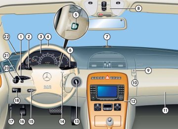
Cockpit
All instruments, switches, buttons and indicator/warning lamps in the passen- ger compartment needed for vehicle operation and monitoring.
COMAND
(Cockpit Management and Data Sys- tem) Information and operating center for vehicle sound and communications systems, including the radio and navi- gation system, as well as other optional equipment (CD changer, telephone, etc.).
420
Technical terms
Engine number
ETD
GPS
The number set by the manufacturer and placed on the cylinder block to uniquely identify each engine pro- duced.
Engine oil viscosity