- 2009 Jeep Liberty Owners Manuals
- Jeep Liberty Owners Manuals
- 2011 Jeep Liberty Owners Manuals
- Jeep Liberty Owners Manuals
- 2010 Jeep Liberty Owners Manuals
- Jeep Liberty Owners Manuals
- 2007 Jeep Liberty Owners Manuals
- Jeep Liberty Owners Manuals
- 2008 Jeep Liberty Owners Manuals
- Jeep Liberty Owners Manuals
- 2005 Jeep Liberty Owners Manuals
- Jeep Liberty Owners Manuals
- 2004 Jeep Liberty Owners Manuals
- Jeep Liberty Owners Manuals
- Download PDF Manual
-
control. † Unequal tire pressures from one side of the vehicle to the other can cause the vehicle to drift to the right or left. † Always drive with each tire inflated to the recommended cold tire inflation pressure.
338 STARTING AND OPERATING
2. Economy— Improper inflation pressures can cause uneven wear patterns to develop across the tire tread. These abnormal wear patterns will reduce tread life resulting in a need for earlier tire replacement. Under inflation also increases tire rolling resistance and results in higher fuel consump- tion. 3. Ride Comfort and Vehicle Stability— Proper tire inflation contributes to a comfortable ride. Over inflation produces a jarring and uncomfortable ride. Both under inflation and over inflation affect the stability of the vehicle and can produce a feeling of sluggish response or over responsiveness in the steering. Unequal tire pressures can cause erratic and unpredict- able steering response. Unequal tire pressure from side to side may cause the vehicle to drift left or right.
Tire Inflation Pressures The proper cold tire inflation pressure is listed on either the face of the driver’s door or the driver’s side “B” pillar.
Tire Placard Location
The pressure should be checked and adjusted as well as inspecting for signs of tire wear or visible damage at least once a month. Use a good quality pocket-type gauge to
check tire pressure. Do not make a visual judgement when determining proper inflation. Radial tires may look properly inflated even when they are under inflated.
CAUTION!
After inspecting or adjusting the tire pressure, al- ways reinstall the valve stem cap (if equipped). This will prevent moisture and dirt from entering the valve stem, which could damage the valve stem.
Inflation pressures specified on the placard are always “cold tire inflation pressure.” Cold tire inflation pressure is defined as the tire pressure after the vehicle has not been driven for at least 3 hours, or driven less than 1 mile (1 km) after a 3 hour period. The cold tire inflation pressure must not exceed the maximum inflation pres- sure molded into the tire sidewall.
STARTING AND OPERATING 339
Check tire pressures more often if subject to a wide range of outdoor temperatures, as tire pressures vary with temperature changes. Tire pressures change by approximately 1 psi (7 kPa) per 12° F (7° C) of air temperature change. Keep this in mind when checking tire pressure inside a garage, especially in the winter. Example: If garage temperature = 68° F (20° C) and the outside temperature = 32° F (0° C) then the cold tire inflation pressure should be increased by 3 psi (21 kPa), which equals 1 psi (7 kPa) for every 12° F (7° C) for this outside temperature condition. Tire pressure may increase from 2 to 6 psi (13 to 40 kPa) during operation. DO NOT reduce this normal pressure build up or your tire pressure will be too low.
340 STARTING AND OPERATING
Tire Pressures for High Speed Operation The manufacturer advocates driving at safe speeds within posted speed limits. Where speed limits or condi- tions are such that the vehicle can be driven at high speeds, maintaining correct tire inflation pressure is very important. Increased tire pressure and reduced vehicle loading may be required for high-speed vehicle opera- tion. Refer to original equipment or an authorized tire dealer for recommended safe operating speeds, loading and cold tire inflation pressures.
WARNING!
High speed driving with your vehicle at or above maximum load is dangerous. The added strain on your tires could cause them to fail. You could have a serious accident. Don’t drive a vehicle loaded to the maximum capacity at continuous speeds above 75
mph (120 km/h).Radial-Ply Tires
WARNING!
Combining radial ply tires with other types of tires on your vehicle will cause your vehicle to handle poorly. The instability could cause an accident. Al- ways use radial tires in sets of four. Never combine them with other types of tires.
Cuts and punctures in radial tires are repairable only in the tread area because of sidewall flexing. Consult your dealer for radial tire repairs. Tire Spinning When stuck in mud, sand, snow, or ice conditions, do not spin your vehicle’s wheels above 35 mph (55 km/h).
WARNING!
Fast spinning tires can be dangerous. Forces gener- ated by excessive wheel speeds may cause tire dam- age or failure. A tire could explode and injure some- one. Do not spin your vehicle’s wheels faster than 35
mph (55 km/h) when you are stuck, and do not let anyone near a spinning wheel no matter what the speed.Tread Wear Indicators Tread wear indicators are in the original equipment tires to help you in determining when your tires should be replaced.
STARTING AND OPERATING 341
These indicators are molded into the bottom of the tread grooves. They will appear as bands when the tread depth becomes 1/16 inch (2 mm). When the indicators appear in 2 or more adjacent grooves, the tire should be replaced. Many states have laws requiring tire replacement at this point.
342 STARTING AND OPERATING
Life of Tire The service life of a tire is dependent upon varying factors including but not limited to: † Driving style † Tire pressure † Distance driven
WARNING!
Tires and spare tire should be replaced after six years, regardless of the remaining tread. Failure to follow this warning can result in sudden tire failure. You could lose control and have an accident resulting in serious injury or death.
Keep dismounted tires in a cool, dry place with as little exposure to light as possible. Protect tires from contact with oil, grease, and gasoline. Replacement Tires The tires on your new vehicle provide a balance of many characteristics. They should be inspected regularly for wear and correct cold tire inflation pressure. The manu- facturer strongly recommends that you use tires equiva- lent to the originals in size, quality and performance when replacement is needed (refer to the paragraph on “Tread Wear Indicators”). Refer to the “Tire and Loading Information” placard for the size designation of your tire. The service description and load identification will be found on the original equipment tire. Failure to use equivalent replacement tires may adversely affect the safety, handling, and ride of your vehicle. We recommend that you contact your original equipment or an autho- rized tire dealer with any questions you may have on tire specifications or capability.
STARTING AND OPERATING 343
WARNING!
CAUTION!
† Do not use a tire, wheel size or rating other than that specified for your vehicle. Some combinations of unapproved tires and wheels may change suspension dimensions and performance characteristics, result- ing in changes to steering, handling, and braking of your vehicle. This can cause unpredictable handling and stress to steering and suspension components. You could lose control and have an accident resulting in serious injury or death. Use only the tire and wheel sizes with load ratings approved for your vehicle. † Never use a tire with a smaller load index or capacity, other than what was originally equipped on your vehicle. Using a tire with a smaller load index could result in tire overloading and failure. You could lose control and have an accident. † Failure to equip your vehicle with tires having ad- equate speed capability can result in sudden tire failure and loss of vehicle control.
Replacing original tires with tires of a different size may result in false speedometer and odometer readings.
Alignment and Balance Poor suspension alignment may result in: † Fast tire wear. † Uneven tire wear, such as feathering and one-sided † Vehicle pull to right or left. Tires may also cause the vehicle to pull left or right. Alignment will not correct this problem. See your autho- rized dealer for proper diagnosis.
wear.
344 STARTING AND OPERATING
Improper alignment will not cause vehicle vibration. Vibration may be a result of tire and wheel out-of- balance. Proper balancing will reduce vibration and avoid tire cupping and spotty wear.
TIRE CHAINS Use only compact chains, or other traction aids that meet SAE type “Class S” specifications. Chains must be the proper size for the vehicle, as recommended by the chain manufacturer. In addition, only install tire chains on P235/65R17 or smaller tires.
CAUTION!
To avoid damage to your vehicle, tires, or chains, observe the following precautions: † Do not use tire chains on vehicles equipped with tires other than P235/65R17 tires. There may not be adequate clearance for the chains and you are risking structural or body damage to your vehicle. † Because of limited chain clearance between tires and other suspension components, it is important that only chains in good condition are used. Broken chains can cause serious vehicle damage. Stop the vehicle immediately if noise occurs that could suggest chain breakage. Remove the damaged parts of the chain before further use. † Install chains on the rear wheels as tightly as possible and then retighten † Do not exceed 45 mph (72 km/h). † Drive cautiously and avoid severe turns and large bumps, especially with † Use on Rear Wheels only. † Do not drive for a prolonged period on dry pavement. † Observe the tire chain manufacturer’s instructions on method of instal- lation, operating speed, and conditions for use. Always use the lower suggested operating speed of the chain manufacturer if different from the speed recommended by the manufacturer.
after driving about 1⁄2 mile (0.8 km).
a loaded vehicle.
These cautions apply to all chain traction devices, includ- ing link and cable (radial) chains.
TIRE ROTATION RECOMMENDATIONS Tires on the front and rear axles of vehicles operate at different loads and perform different steering, handling, and braking functions. For these reasons, they wear at unequal rates, and develop irregular wear patterns. These effects can be reduced by timely rotation of tires. The benefits of rotation are especially worthwhile with aggressive tread designs such as those on On/Off Road type tires. Rotation will increase tread life, help to main- tain mud, snow, and wet traction levels, and contribute to a smooth, quiet ride.
STARTING AND OPERATING 345
Follow the “Maintenance Schedule” in Section 8 of this manual for the recommended tire rotation frequency. Remember, more frequent rotation is permissible if de- sired. Also, correct for anything causing rapid or unusual wear prior to performing the tire rotation. The suggested rotation method is the “forward-cross” shown in the following diagram.
346 STARTING AND OPERATING
TIRE PRESSURE MONITOR SYSTEM (TPMS) — IF EQUIPPED † The Tire Pressure Monitor System (TPMS) will warn the driver of a low tire pressure based on the vehicle recommended cold placard pressure. † The tire pressure will vary with temperature by about 1 psi (6.9 kPa) for every 12°F (6.5°C). This means that when the outside temperature decreases, the tire pres- sure will decrease. Tire pressure should always be set based on cold inflation tire pressure. This is defined as the tire pressure after the vehicle has not been driven for at least 3 hours, or driven less than 1 mile (1 km) after a 3 hour period. The cold tire inflation pressure must not exceed the maximum inflation pressure molded into the tire sidewall. Refer to the “Tires – General Information” in this section for information on how to properly inflate the vehicle’s tires. The tire
pressure will also increase as the vehicle is driven - this is normal and there should be no adjustment for this increased pressure. † The TPM System will warn the driver of a low tire pressure if the tire pressure falls below the low- pressure warning limit for any reason, including low temperature effects and natural pressure loss through the tire. † The TPM System will continue to warn the driver of low tire pressure as long as the condition exists, and will not turn off until the tire pressure is at or above the recommended cold placard pressure. Once the low tire pressure warning (Tire Pressure Monitoring Tell- tale Light) illuminates, you must increase the tire pressure to the recommended cold placard pressure in order for the Tire Pressure Monitoring Telltale Light to turn off. The system will automatically update and the Tire Pressure Monitoring Telltale Light will turn off
once the system receives the updated tire pressures. The vehicle may need to be driven for up to 10 minutes above 15 mph (25 km/h) in order for the TPMS to receive this information. − For example, your vehicle may have a recom- mended cold (parked for more than 3 hours) placard pressure of 33 psi (227 kPa). If the ambient tempera- ture is 68°F (20°C) and the measured tire pressure is 28 psi (193 kPa), a temperature drop to 20°F (-7°C) will decrease the tire pressure to approximately 24
psi (165 kPa). This tire pressure is sufficiently low enough to turn ON the Tire Pressure Monitoring Telltale light. Driving the vehicle may cause the tire pressure to rise to approximately 28 psi (193 kPa), but the Tire Pressure Monitoring Telltale Light will still be ON. In this situation, the Tire Pressure Monitoring Telltale Light will turn OFF only after the tires are inflated to the vehicle’s recommended cold placard pressure value.STARTING AND OPERATING 347
CAUTION!
† The TPMS has been optimized for the original equipment tires and wheels. TPMS pressures and warning have been established for the tire size equipped on your vehicle. Undesirable system operation or sensor damage may result when us- ing replacement equipment that is not of the same size, type, and/or style. Aftermarket wheels can cause sensor damage. Do not use aftermarket tire sealants or balance beads if your vehicle is equipped with a TPMS, as damage to the sensors may result. † After inspecting or adjusting the tire pressure, always reinstall the valve stem cap. This will prevent moisture and dirt from entering the valve stem, which could damage the Tire Pressure Moni- toring Sensor.
348 STARTING AND OPERATING
while adjusting your tire pressure.
NOTE: † The TPMS is not intended to replace normal tire care and maintenance, or to provide warning of a tire failure or condition. † The TPMS should not be used as a tire pressure gauge † Driving on a significantly under-inflated tire causes the tire to overheat and can lead to tire failure. Under-inflation also reduces fuel efficiency and tire tread life, and may affect the vehicle’s handling and stopping ability. † The TPMS is not a substitute for proper tire mainte- nance, and it is the driver’s responsibility to maintain correct tire pressure using an accurate tire pressure gauge, even if under-inflation has not reached the level to trigger illumination of the Tire Pressure Moni- toring Telltale light.
† Seasonal temperature changes will affect tire pressure, and the TPMS will monitor the actual tire pressure in the tire.
Base System — If Equipped The Tire Pressure Monitor System (TPMS) uses wireless technology with wheel rim mounted electronic sensors to monitor tire pressure levels. Sensors, mounted to each wheel as part of the valve stem, transmit tire pressure readings to the Receiver Module. It is particularly important for you to check the NOTE: tire pressure in all of the tires on your vehicle monthly and to maintain the proper pressure. The TPMS consists of the following components: † Receiver Module † 4 Tire Pressure Monitoring Sensors † Tire Pressure Monitoring Telltale Light
The matching full size spare wheel and tire assembly (if equipped) has a tire pressure monitoring sensor. The matching full size spare can be used in place of any of the four road tires. The TPMS will only monitor the pressure in the full size spare when it is used in place of a road tire. Otherwise, a spare with a pressure below the low- pressure limit will not cause the Tire Pressure Monitoring Telltale Light to illuminate or the chime to sound. Tire Pressure Monitoring Low Pressure Warnings
The Tire Pressure Monitoring Telltale Light will illuminate in the instrument cluster and a chime will sound when tire pressure is low in one or more of the four active road tires. Should this occur, you should stop as soon as possible, check the inflation pressure of each tire on your vehicle, and inflate each tire to the vehicle’s recommended cold placard pressure value. Once the system receives the updated tire pres- sures, the system will automatically update and the Tire Pressure Monitoring Telltale Light will turn off. The
STARTING AND OPERATING 349
vehicle may need to be driven for up to 10 minutes above 15 mph (25 km/h) in order for the TPMS to receive this information. Check TPMS Warning When a system fault is detected, the Tire Pressure Moni- toring Telltale Light will flash on and off for 75 seconds and then remain on solid. The system fault will also sound a chime. If the ignition key is cycled, this sequence will repeat, providing the system fault still exists. The Tire Pressure Monitoring Telltale Light will turn off when the fault condition no longer exists. A system fault can occur due to any of the following: 1. Jamming due to electronic devices or driving next to facilities emitting the same Radio Frequencies as the TPM sensors. 2. Installing some form of aftermarket window tinting that affects radio wave signals.
350 STARTING AND OPERATING
3. Lots of snow or ice around the wheels or wheel housings. 4. Using tire chains on the vehicle. 5. Using wheels/tires not equipped with TPM sensors. NOTE:
Vehicles with Full Size Spare 1. The matching full size spare wheel and tire assembly has a tire pressure monitoring sensor that can be moni- tored by the TPMS. 2. If you install the full size spare in place of a road tire that has a pressure below the low-pressure warning limit, upon the next ignition key cycle, a chime will sound and the TPM Telltale Light will turn ON. 3. Driving the vehicle for up to 10 minutes above 15 mph (25 km/h) will turn off the TPM Telltale Light, as long as no tire pressure is below the low-pressure warning limit in any of the four active road tires.
NOTE:
Vehicles with Compact Spare 1. The compact spare tire does not have a tire pressure monitoring sensor. Therefore, the TPMS will not monitor the pressure in the compact spare tire. 2. If you install the compact spare tire in place of a road tire that has a pressure below the low-pressure warning limit, upon the next ignition key cycle, a chime will sound and the TPM Telltale Light will turn ON. 3. After driving the vehicle for up to 10 minutes above 15
mph (25 km/h), the TPM Telltale Light will flash on and off for 75 seconds and then remain on solid. 4. For each subsequent ignition key cycle, a chime will sound and the TPM Telltale Light will flash on and off for 75 seconds and then remain on solid. 5. Once you repair or replace the original road tire, and reinstall it on the vehicle in place of the compact spare, the TPMS will update automatically and the TPM Telltale Light will turn OFF, as long as no tire pressure is belowthe low-pressure warning limit in any of the four active road tires. The vehicle may need to be driven for up to 10
minutes above 15 mph (25 km/h) in order for the TPMS to receive this information. Premium System — If Equipped The Tire Pressure Monitor System (TPMS) uses wireless technology with wheel rim mounted electronic sensors to monitor tire pressure levels. Sensors, mounted to each wheel as part of the valve stem, transmit tire pressure readings to the Receiver Module. It is particularly important for you to check the NOTE: tire pressure in all of the tires on your vehicle monthly and to maintain the proper pressure. The TPMS consists of the following components: † Receiver Module † 4 Tire Pressure Monitoring SensorsSTARTING AND OPERATING 351
wheel-wells)
† 3 Trigger Modules (mounted in three of the four † Various Tire Pressure Monitoring System Messages, which display in the Electronic Vehicle Information Center (EVIC)
† Tire Pressure Monitoring Telltale Light The matching full size spare wheel and tire assembly (if equipped) has a tire pressure monitoring sensor. The full size spare can be used in place of any of the four road tires. A spare with a pressure below the low-pressure limit will not cause the Tire Pressure Monitoring Telltale Light to illuminate or the chime to sound. However, it will cause a “SPARE LOW PRESSURE” message to display in the EVIC. Tire Pressure Monitoring Low Pressure Warnings
The Tire Pressure Monitoring Telltale Light will illuminate in the instrument cluster and a chime
352 STARTING AND OPERATING
will sound when tire pressure is low in one or more of the four active road tires. In addition, the Electronic Vehicle Information Center (EVIC) will display a graphic show- ing the pressure values of each tire with the low tire pressure values flashing.
Should this occur, you should stop as soon as possible, and inflate the tires with low pressure (those flashing in the EVIC graphic) to the vehicle’s recommended cold placard pressure value. Once the system receives the updated tire pressures, the system will automatically update, the graphic display in the EVIC will stop flash- ing, and the Tire Pressure Monitoring Telltale Light will turn off. The vehicle may need to be driven for up to 10
minutes above 15 mph (25 km/h) in order for the TPMS to receive this information. Check TPMS Warning When a system fault is detected, the Tire Pressure Moni- toring Telltale Light will flash on and off for 75 seconds and then remain on solid. The system fault will also sound a chime. In addition, the EVIC will display a 9CHECK TPM SYSTEM9 message for 3 seconds and then display dashes (- -) in place of the pressure value to indicate which sensor is not being received.STARTING AND OPERATING 353
1. Jamming due to electronic devices or driving next to facilities emitting the same Radio Frequencies as the TPM sensors. 2. Installing some form of aftermarket window tinting that affects radio wave signals. 3. Lots of snow or ice around the wheels or wheel housings. 4. Using tire chains on the vehicle. 5. Using wheels/tires not equipped with TPM sensors. NOTE:
Vehicles with Full Size Spare 1. The matching full size spare wheel and tire assembly has a tire pressure monitoring sensor that can be moni- tored by the TPMS. 2. If you install the full size spare in place of a road tire that has a pressure below the low-pressure warning limit,
If the ignition key is cycled, this sequence will repeat, providing the system fault still exists. If the system fault no longer exists, the Tire Pressure Monitoring Telltale Light will no longer flash, and the 9CHECK TPM SYS- TEM9 message will no longer display, and a pressure value will display in place of the dashes. A system fault can occur due to any of the following:
354 STARTING AND OPERATING
upon the next ignition key cycle, a chime will sound and the TPM Telltale Light will turn ON. In addition, the EVIC will display a Low Pressure message and a graphic showing the low tire pressure value flashing. 3. After driving the vehicle for up to 10 minutes above 15
mph (25 km/h) the TPM Telltale Light will turn OFF, as long as no tire pressure is below the low-pressure warn- ing limit in any of the four active road tires. 4. The EVIC will display a graphic showing the tire pressure value in place of the flashing low tire pressure value. The EVIC will also display a “SPARE LOW PRESSURE” message to remind you to service the flat tire. NOTE:Vehicles with Compact Spare 1. The compact spare tire does not have a tire pressure monitoring sensor. Therefore, the TPMS will not monitor the pressure in the compact spare tire.
2. If you install the compact spare tire in place of a road tire that has a pressure below the low-pressure warning limit, upon the next ignition key cycle, the TPM Telltale Light will remain ON and a chime will sound. In addition, the graphic in the EVIC will still display a flashing pressure value. 3. After driving the vehicle for up to 10 minutes above 15
mph (25 km/h), the TPM Telltale Light will flash on and off for 75 seconds and then remain on solid. In addition, the EVIC will display a 9CHECK TPM SYSTEM9 message for 3 seconds and then display dashes (- -) in place of the pressure value. 4. For each subsequent ignition key cycle, a chime will sound, the TPM Telltale Light will flash on and off for 75
seconds and then remain on solid, and the EVIC will display a 9CHECK TPM SYSTEM9 message for 3 seconds and then display dashes (- -) in place of the pressure value.5. Once you repair or replace the original road tire, and reinstall it on the vehicle in place of the compact spare, the TPMS will update automatically. In addition, the TPM Telltale Light will turn OFF and the graphic in the EVIC will display a new pressure value instead of dashes (- -), as long as no tire pressure is below the low-pressure warning limit in any of the four active road tires. The vehicle may need to be driven for up to 10 minutes above 15 mph (25 km/h) in order for the TPMS to receive this information. General Information This device complies with part 15 of the FCC rules and RSS 210 of Industry Canada. Operation is subject to the following conditions: † This device may not cause harmful interference. † This device must accept any interference received, including interference that may cause undesired op- eration.
STARTING AND OPERATING 355
The tire pressure sensors are covered under one of the following licenses:
United States . . . . . . . . . . . . . . . . . . . . . KR5S120123
Canada . . . . . . . . . . . . . . . . . . . . . . . . 2671-S120123FUEL REQUIREMENTS
Your engine is designed to meet all emis- sions regulations and provide excellent fuel economy and performance when us- ing high quality unleaded “regular” gaso- line having an octane rating of 87. The use of premium gasoline is not recommended. Under normal conditions, the use of premium gasoline will not provide a benefit over high quality regular gasolines, and in some circumstances may result in poorer performance. Light spark knock at low engine speeds is not harmful to your engine. However, continued heavy spark knock at
356 STARTING AND OPERATING
high speeds can cause damage and immediate service is required. Poor quality gasoline can cause problems such as hard starting, stalling, and hesitations. If you experi- ence these symptoms, try another brand of gasoline before considering service for the vehicle. Over 40 auto manufacturers worldwide have issued and endorsed consistent gasoline specifications (the World- wide Fuel Charter, WWFC) which define fuel properties necessary to deliver enhanced emissions, performance, and durability for your vehicle. The manufacturer recom- mends the use of gasoline that meets the WWFC speci- fications if they are available. Reformulated Gasoline Many areas of the country require the use of cleaner burning gasoline referred to as “Reformulated Gasoline.” Reformulated gasolines contain oxygenates, and are spe- cifically blended to reduce vehicle emissions and im- prove air quality.
The manufacturer supports the use of reformulated gaso- lines. Properly blended reformulated gasolines will pro- vide excellent performance and durability of engine and fuel system components. Gasoline/Oxygenate Blends Some fuel suppliers blend unleaded gasoline with oxy- genates such as 10% ethanol, MTBE, and ETBE. Oxygen- ates are required in some areas of the country during the winter months to reduce carbon monoxide emissions. Fuels blended with these oxygenates may be used in your vehicle.
CAUTION!
DO NOT use gasolines containing Methanol or E85
Ethanol. Use of these blends may result in starting and driveability problems and may damage critical fuel system components.Problems that result from using methanol/gasoline or E85 Ethanol blends are not the responsibility of the manufacturer. While MTBE is an oxygenate made from Methanol, it does not have the negative effects of Metha- nol. MMT In Gasoline MMT is a manganese containing metallic additive that is blended into some gasoline to increase octane. Gasoline blended with MMT provides no performance advantage beyond gasoline of the same octane number without MMT. Gasoline blended with MMT reduces spark plug life and reduces emission system performance in some vehicles. The manufacturer recommends that gasoline without MMT be used in your vehicle. The MMT content of gasoline may not be indicated on the gasoline pump; therefore, you should ask your gasoline retailer whether his/her gasoline contains MMT. It is even more impor- tant to look for gasolines without MMT in Canada, because MMT can be used at levels higher than those
STARTING AND OPERATING 357
allowed in the United States. MMT is prohibited in Federal and California reformulated gasoline. Materials Added to Fuel All gasoline sold in the United States is required to contain effective detergent additives. Use of additional detergents or other additives is not needed under normal conditions and they would result in additional cost. Therefore, you should not have to add anything to the fuel. Fuel System Cautions
CAUTION!
Follow these guidelines to maintain your vehicle’s performance:
358 STARTING AND OPERATING
† The use of leaded gas is prohibited by Federal law. Using leaded gasoline can impair engine performance, and damage the emission control system. † An out-of-tune engine, or certain fuel or ignition malfunctions, can cause the catalytic converter to overheat. If you notice a pungent burning odor or some light smoke, your engine may be out of tune or malfunctioning and may require immediate service. Contact your dealer for service assistance. † The use of fuel additives, which are now being sold as octane enhancers, is not recommended. Most of these products contain high concentrations of methanol. Fuel system damage or vehicle performance problems resulting from the use of such fuels or additives is not the responsibility of the manufacturer.
NOTE: systems can result against you.
Intentional tampering with emissions control in civil penalties being assessed
Carbon Monoxide Warnings
WARNING!
Carbon monoxide (CO) in exhaust gases is deadly. Follow the precautions below to prevent carbon monoxide poisoning:
† Do not inhale exhaust gases. They contain carbon monoxide, a colorless and odorless gas, which can kill. Never run the engine in a closed area, such as a garage, and never sit in a parked vehicle with the engine running for an extended period. If the vehicle is stopped in an open area with the engine running for more than a short period, adjust the ventilation system to force fresh, outside air into the vehicle.
† Guard against carbon monoxide with proper mainte- nance. Have the exhaust system inspected every time the vehicle is raised. Have any abnormal conditions repaired promptly. Until repaired, drive with all side windows fully open. † Keep the trunk closed when driving your vehicle to prevent carbon monoxide and other poisonous ex- haust gases from entering the vehicle.
ADDING FUEL
Fuel Filler Cap (Gas Cap) The gas cap is located behind the fuel filler door on the left side of the vehicle. If the gas cap is lost or damaged, be sure the replacement cap is designed for use with this vehicle.
STARTING AND OPERATING 359
Fuel Filler Cap (Gas Cap)
360 STARTING AND OPERATING
CAUTION!
the fuel system.
† Damage to the fuel system or emission control system could result from using an improper fuel tank filler tube cap (gas cap). † A poorly fitting gas cap could let impurities into † A poorly fitting gas cap may cause the Malfunc- † To avoid fuel spillage and overfilling, do not “top off” the fuel tank after filling. When the fuel nozzle “clicks” or shuts off, the fuel tank is full.
tion Indicator Light to turn on.
WARNING!
† Never have any smoking materials lit in or near the vehicle when the gas cap is removed or the tank filled. † Never add fuel to the vehicle when the engine is † A fire may result if gasoline is pumped into a portable container that is inside of a vehicle. You could be burned. Always place gas containers on the ground while filling.
running.
NOTE: † Tighten the gas cap until you hear a “clicking” sound. This is an indication that the gas cap is tightened properly. The Malfunction Indicator Light in the in- strument cluster may turn on if the gas cap is not secured properly. Make sure that the gas cap is tight- ened each time the vehicle is refueled. † When the fuel nozzle “clicks” or shuts off, the fuel
tank is full.
Loose Fuel Filler Cap Message If the vehicle diagnostic system determines that the fuel filler cap in loose, improperly installed, or damaged, a “gASCAP” message will display in the instrument clus- ter. Tighten the gas cap until a “clicking” sound is heard. This is an indication that the gas cap is properly tight- ened. Press the trip odometer reset button to turn off the message. If the problem persists, the message will appear the next time the vehicle is started. This might indicate a
STARTING AND OPERATING 361
damaged cap. If the problem is detected twice in a row, the system will turn on the Malfunction Indicator Light (MIL). Resolving the problem will turn the MIL light off.
VEHICLE LOADING
Certification Label As required by National Highway Traffic Safety Admin- istration Regulations, your vehicle has a certification label affixed to the driver’s side door or pillar. This label contains the month and year of manufacture, Gross Vehicle Weight Rating (GVWR), Gross Axle Weight Rating (GAWR) front and rear, and Vehicle Identification Number (VIN). A Month-Day-Hour (MDH) number is included on this label and indicates the Month, Day, and Hour of manufacture. The bar code that appears on the bottom of the label is your Vehicle Identification Number (VIN).
362 STARTING AND OPERATING
Gross Vehicle Weight Rating (GVWR) The GVWR is the total permissible weight of your vehicle including driver, passengers, vehicle, options, trailer tongue weight, and cargo. The label also specifies maxi- mum capacities of front and rear axle systems (GAWR). Total load must be limited, so GVWR, and front and rear GAWR are not exceeded. Payload The payload of a vehicle is defined as the allowable load weight a truck can carry, including the weight of the driver, all passengers, options and cargo. Gross Axle Weight Rating (GAWR) The GAWR is the maximum permissible load on the front and rear axles. The load must be distributed in the cargo area so that the GAWR of each axle is not exceeded.
Each axle GAWR is determined by the components in the system with the lowest load carrying capacity (axle, springs, tires, or wheels). Heavier axles or suspension components sometimes specified by purchasers for in- creased durability does not necessarily increase the vehi- cle’s GVWR. Tire Size The tire size on the Label represents the actual tire size on your vehicle. Replacement tires must be equal to the load capacity of this tire size. Rim Size This is the rim size that is appropriate for the tire size listed. Inflation Pressure This is the cold tire inflation pressure for your vehicle for all loading conditions up to full GAWR.
Curb Weight The curb weight of a vehicle is defined as the total weight of the vehicle with all fluids, including vehicle fuel, at full capacity conditions, and with no occupants or cargo loaded into the vehicle. The front and rear curb weight values are determined by weighing your vehicle on a commercial scale before any occupants or cargo are added. Loading The actual total weight and the weight of the front and rear of your vehicle at the ground can best be determined by weighing it when it is loaded and ready for operation. The entire vehicle should first be weighed on a commer- cial scale to insure that the GVWR has not been exceeded. The weight on the front and rear of the vehicle should then be determined separately to be sure that the load is properly distributed over front and rear axle. Weighing the vehicle may show that the GAWR of either the front
STARTING AND OPERATING 363
or rear axles has been exceeded but the total load is within the specified GVWR. If so, weight must be shifted from front to rear or rear to front as appropriate until the specified weight limitations are met. Store the heavier items down low and be sure that the weight is distributed equally. Stow all loose items securely before driving. Improper weight distributions can have an adverse effect on the way your vehicle steers and handles and the way the brakes operate.
CAUTION!
Do not load your vehicle any heavier than the GVWR or the maximum front and rear GAWR. If you do, parts on your vehicle can break, or it can change the way your vehicle handles. This could cause you to lose control. Also overloading can shorten the life of your vehicle.
364 STARTING AND OPERATING
TRAILER TOWING In this section, you will find safety tips and information on limits to the type of towing you can reasonably do with your vehicle. Before towing a trailer, carefully review this information to tow your load as efficiently and safely as possible. To maintain warranty coverage, follow the requirements and recommendations in this manual concerning ve- hicles used for trailer towing. Common Towing Definitions The following trailer towing related definitions will assist you in understanding the following information: Gross Vehicle Weight Rating (GVWR) The Gross Vehicle Weight Rating (GVWR) is the total allowable weight of your vehicle. This includes driver, passengers, cargo, and tongue weight. The total load must be limited so that you do not exceed the GVWR.
Gross Trailer Weight (GTW) The Gross Trailer Weight (GTW) is the weight of the trailer plus the weight of all cargo, consumables, and equipment (permanent or temporary) loaded in or on the trailer in its 9loaded and ready for operation9 condition. The recommended way to measure GTW is to put your fully loaded trailer on a vehicle scale. The entire weight of the trailer must be supported by the scale.
WARNING!
it
If the Gross Trailer Weight (GTW) is 3,500 lbs. (1 587
kg) or more, is mandatory to use a weight- distributing hitch to ensure stable handling of your vehicle. If you use a standard weight- carrying hitch, you could lose control of your vehicle and cause an accident.Gross Combination Weight Rating (GCWR) The Gross Combination Weight Rating (GCWR) is the total permissible weight of your vehicle and trailer when weighed in combination. (Note that GCWR ratings in- clude a 150 lbs (68 kg) allowance for the presence of a driver). Gross Axle Weight Rating (GAWR) The Gross Axle Weight Rating (GAWR) is the maximum capacity of the front and rear axles. Distribute the load over the front and rear axles evenly. Make sure that you do not exceed either front or rear GAWR.
WARNING!
It is important that you do not exceed the maximum front or rear GAWR. A dangerous driving condition can result if either rating is exceeded. You could lose control of the vehicle and have an accident.
STARTING AND OPERATING 365
Tongue Weight (TW) Tongue weight (TW) is the downward force exerted on the hitch ball by the trailer. In most cases, it should not be less than 10% or more than 15% of the trailer load. You must consider this as part of the load on your vehicle. Frontal Area Frontal area is the maximum height and maximum width of the front of a trailer. Trailer Sway Control — Electronic Refer to “TSC (Trailer Sway Control)” under “Electronic Brake Control System” in this section for information on this system. Trailer Sway Control — Mechanical The trailer sway control is a telescoping link that can be installed between the hitch receiver and the trailer tongue that typically provides adjustable friction associated with the telescoping motion to dampen any unwanted trailer swaying motions while traveling.
366 STARTING AND OPERATING
Weight-Carrying Hitch A weight-carrying hitch supports the trailer tongue weight, just as if it were luggage located at a hitch ball or some other connecting point of the vehicle. These kinds of hitches are the most popular on the market today and they’re commonly used to tow small- and medium-sized trailers. Weight-Distributing Hitch A weight-distributing system works by applying lever- age through spring (load) bars. They are typically used for heavier loads, to distribute trailer tongue weight to the tow vehicle’s front axle and the trailer axle(s). When used in accordance with the manufacturers’ directions, it provides for a more level ride, offering more consistent steering and brake control thereby enhancing towing safety. The addition of a friction/hydraulic sway control also dampens sway caused by traffic and crosswinds and contributes positively to tow vehicle and trailer stability. Trailer sway control and a weight distributing (load
equalizing) hitch are recommended for heavier Tongue Weights (TW) and may be required depending on Vehicle and Trailer configuration/loading to comply with Gross Axle Weight Rating (GAWR) requirements.
WARNING!
An improperly adjusted Weight Distributing Hitch system may reduce handling, stability, braking per- formance, and could result in an accident. Weight Distributing Systems may not be compatible with Surge Brake Couplers. Consult with your hitch and trailer manufacturer or a reputable Recreational Vehicle dealer for additional information.
STARTING AND OPERATING 367
Weight Distributing Hitch System
Improper Adjustment of Weight Distributing System
368 STARTING AND OPERATING
Trailer Hitch Classification Your vehicle is capable of towing trailers up to 2,000 lbs (907 kg) without added equipment or alterations to the standard equipment. Your vehicle may be factory equipped for safe towing of trailers weighing over 2,000
lbs (907 kg) with the optional Trailer Tow Prep Package. See your dealer for package content. The following chart provides the industry standard for the maximum trailer weight a given trailer hitch class can tow and should be used to assist you in selecting the correct trailer hitch for your intended towing condition. Refer to the “Trailer Towing Weights (Maximum Trailer Weight Ratings)” chart for the Max. GTW towable for your given drivetrain.Trailer Hitch Classification
Class
Max. GTW
(Gross Trailer Wt.) 2,000 lbs (907 kg) 3,500 lbs (1 587 kg)
Class I - Light Duty Class II - Medium Duty Class III - Heavy Duty Class IV - Extra Heavy Duty All trailer hitches should be professionally installed on your vehicle.
5,000 lbs (2 268 kg) 10,000 lbs (4 540 kg)
Trailer Towing Weights (Maximum Trailer Weight Ratings) The following chart provides the maximum trailer weight ratings towable for your given drivetrain.
STARTING AND OPERATING 369
Engine/Transmission
Model
3.7L/6-Speed Manual
3.7L/6-Speed Manual
3.7L/Automatic
3.7L/Automatic
3.7L/Automatic w/
Cooler
3.7L/Automatic
w/Cooler
4x2
4x4
4x2
4x4
4x2
4x4
GCWR (Gross Com- bined Wt. Rating) 8,500 lbs (3 855 kg)
8,750 lbs (3 969 kg)
7,150 lbs (3 243 kg)
7,400 lbs ( 3 356 kg)
9,850 lbs (4 468 kg)
10,100 lbs (4 581 kg)
Frontal Area
40 Sq. Ft. (3.72
square meters) 40 Sq. Ft. (3.72
square meters) 32 Sq. Ft. (2.97
square meters) 32 Sq. Ft. (2.97
square meters) 64 Sq. Ft. (5.94
square meters) 64 Sq. Ft. (5.94
square meters)Max. GTW
(Gross Trailer Wt.) 3,500 lbs (1 587 kg) 350 lbs (159 kg)
Tongue Wt. (See Note)
3,500 lbs (1 587 kg) 350 lbs (159 kg)
2,000 lbs (907 kg)
200 lbs (91 kg)
2,000 lbs (907 kg)
200 lbs (91 kg)
3,500 lbs (1 588 kg) 350 lbs (159 kg)
3,500 lbs (1 588 kg) 350 lbs (159 kg)
Refer to local laws for maximum trailer towing speeds.
NOTE: The trailer tongue weight must be considered as part of the combined weight of occupants and cargo, and it should never exceed the weight referenced on the “Tire and Loading Information” placard. Refer to “Tire–Safety Information” in this section.
370 STARTING AND OPERATING
When Towing Trailers with Gross Trailer Weight (GTW) between 3,500 Lbs (1 588 kg) and 5,000 Lbs (2 268 kg) The following chart provides maximum trailer weight ratings towable for the following engine/transmission combinations, ONLY if using a weight distributing hitch.
Engine/
Transmission
Model
Automatic w/
3.7L/
Cooler 3.7L/
Automatic w/Cooler
4x2
4x4
GCWR (Gross Com- bined Wt. Rating) 9,850 lbs (4 468 kg)
10,100 lbs (4 581 kg)
Frontal Area
64 Sq. Ft. (5.94
square meters)64 Sq. Ft. (5.94
square meters)Max. GTW
(Gross Trailer Wt.) 5,000 lbs (2 268 kg)
Tongue Wt. (See Note)
500 lbs (227 kg)
5,000 lbs (2 268 kg)
500 lbs (227 kg)
Refer to local laws for maximum trailer towing speeds.
NOTE: The trailer tongue weight must be considered as part of the combined weight of occupants and cargo, and it should never exceed the weight referenced on the “Tire and Loading Information” placard. Refer to “Tire–Safety Information” in this section.
Trailer and Tongue Weight Always load a trailer with 60% to 65% of the weight in the front of the trailer. This places 10% to 15% of the Gross Trailer Weight (GTW) on the tow hitch of your vehicle. Loads balanced over the wheels or heavier in the rear can cause the trailer to sway severely side to side which will cause loss of control of vehicle and trailer. Failure to load trailers heavier in front is the cause of many trailer accidents. Never exceed the maximum tongue weight stamped on your bumper or trailer hitch.
STARTING AND OPERATING 371
Consider the following items when computing the weight on the rear axle of the vehicle: † The tongue weight of the trailer. † The weight of any other type of cargo or equipment † The weight of the driver and all passengers.
put in or on your vehicle.
372 STARTING AND OPERATING
NOTE: Remember that everything put into or on the trailer adds to the load on your vehicle. Also, additional factory-installed options, or dealer-installed options, must be considered as part of the total load on your vehicle. Refer to the “Tire and Loading Information” placard for the maximum combined weight of occupants and cargo for your vehicle. Towing Requirements To promote proper break-in of your new vehicle drivetrain components the following guidelines are recommended:
CAUTION!
† Avoid towing a trailer for the first 500 miles (805
km) of vehicle operation. Doing so may damage your vehicle. † During the first 500 miles (805 km) of trailertowing, limit your speed to 50 mph (80 km/h).
Perform the maintenance listed in Section 8 of this manual. When towing a trailer, never exceed the GAWR, or GCWR, ratings.
WARNING!
Improper towing can lead to an injury accident. Follow these guidelines to make your trailer towing as safe as possible: Make certain that the load is secured in the trailer and that is will not shift during travel. When traile- ring cargo that is not fully secured, dynamic load shifts can occur that may be difficult for the driver to control. You could lose control of your vehicle and have an accident.
† When hauling cargo, or towing a trailer, do not overload your vehicle or trailer. Overloading can cause a loss of control, poor performance, or damage to brakes, axle, engine, transmission, steering, suspen- sion, chassis structure, or tires. † Safety chains must always be used between your vehicle and trailer. Always connect the chains to the frame or hook retainers of the vehicle hitch. Cross the chains under the trailer tongue and allow enough slack for turning corners. † Vehicles with trailers should not be parked on a grade. When parking, apply the parking brake on the tow vehicle. Put the tow vehicle automatic transmission in “P” (Park). With a manual transmission, shift the transmission into “R” (Reverse). Always, block or 9chock9 the trailer wheels.
† GCWR must not be exceeded.
STARTING AND OPERATING 373
† Total weight must be distributed between the tow vehicle and the trailer such that the following four ratings are not exceeded: 1. GVWR 2. GTW 3. GAWR 4. Tongue weight rating for the trailer hitch utilized (This requirement may limit the ability to always achieve the 10% to 15% range of tongue weight as a percentage of total trailer weight).
Towing Requirements — Tires − Do not attempt to tow a trailer while using a compact
spare tire.
374 STARTING AND OPERATING
− Proper tire inflation pressures are essential to the safe and satisfactory operation of your vehicle. Refer to “Tires–General Information” in this section for infor- mation on tire pressures and for proper tire inflation procedures.
− Also, check the trailer tires for proper tire inflation
pressures before trailer usage.
− Check for signs of tire wear or visible tire damage before towing a trailer. Refer to “Tires–General Infor- mation” in this section for information on tread wear indicators and for the proper inspection procedure.
− When replacing tires, refer to “Tires–General Informa- tion” in this section for information on replacement tires and for the proper tire replacement procedures. Replacing tires with a higher load carrying capacity will not increase the vehicle’s GVWR and GAWR limits.
Towing Requirements — Trailer Brakes − Do not interconnect the hydraulic brake system or vacuum system of your vehicle with that of the trailer. This could cause inadequate braking and possible personal injury.
− An electronically actuated trailer brake controller is required when towing a trailer with electronically actuated brakes. When towing a trailer equipped with a hydraulic surge actuated brake system, an electronic brake controller is not required.
− Trailer brakes are recommended for trailers over 1,000
lbs (454 kg) and required for trailers in excess of 2,000
lbs (907 kg).STARTING AND OPERATING 375
Towing Requirements — Trailer Lights & Wiring Whenever you pull a trailer, regardless of the trailer size, stoplights and turn signals on the trailer are required for motoring safety. The Trailer Tow Package may include a 4 and 7 pin wiring harness. Use a factory approved trailer harness and connector. NOTE: Do not cut or splice wiring into the vehicles wiring harness.
CAUTION!
If the trailer weighs more than 1,000 lbs (454 kg) loaded, it should have its own brakes, and they should be of adequate capacity. Failure to do this could lead to accelerated brake lining wear, higher brake pedal effort, and longer stopping distances.
WARNING!
Do not connect trailer brakes to your vehicle’s hy- draulic brake lines. It can overload your brake sys- tem and cause it to fail. You might not have brakes when you need them and could have an accident. Towing any trailer will increase your stopping dis- tance. When towing you should allow for additional space between your vehicle and the vehicle in front of you. Failure to do so could result in an accident.
376 STARTING AND OPERATING
The electrical connections are all complete to the vehicle but you must mate the harness to a trailer connector. Refer to the following illustrations.
4 - Pin Connector
7- Pin Connector
Towing Tips Before setting out on a trip, practice turning, stopping, and backing the trailer in an area located away from heavy traffic. If using a manual transmission vehicle for trailer towing, all starts must be in FIRST gear to avoid excessive clutch slippage. Towing Tips — Automatic Transmission The “D” range can be selected when towing. However, if frequent shifting occurs while in this range, you will want to activate the TOW/HAUL feature. Refer to “Au- tomatic Transmission” in this section for additional in- formation. NOTE: Using the TOW/HAUL feature while operating the vehicle under heavy operating conditions will im- prove performance and extend transmission life by re- ducing excessive shifting and heat build up. This action will also provide better engine braking.
STARTING AND OPERATING 377
If you REGULARLY tow a trailer for more than 45
minutes of continuous operation, then change the auto- matic transmission fluid and filter according to the interval specified for “police, taxi, fleet, or frequent trailer towing” in the “Maintenance Schedule” in this manual. Towing Tips — TOW/HAUL To reduce potential for automatic transmission overheat- ing, press the “TOW HAUL” button when driving in hilly areas or shift the transmission to Drive position “2” on more severe grades. Refer to “Automatic Transmis- sion” in this section for additional information. Towing Tips — Electronic Speed Control (If Equipped) − Don’t use in hilly terrain or with heavy loads. − When using the speed control, if you experience speed drops greater than 10 mph (16 km/h), disengage until you can get back to cruising speed.378 STARTING AND OPERATING
− Use speed control in flat terrain and with light loads to
maximize fuel efficiency.
Towing Tips — Cooling System To reduce potential for engine and transmission over- heating, take the following actions: − City Driving When stopped for short periods of time, put transmission in neutral and increase engine idle speed. − Highway Driving Reduce speed. − Air Conditioning Turn off temporarily. − Refer to “Cooling System” under “Maintenance Pro- cedures” in Section 7 of this manual for more informa- tion.
RECREATIONAL TOWING (BEHIND MOTORHOME, ETC.)
Towing – 2WD Models Recreational towing is not allowed.
CAUTION!
Towing with the rear wheels on the ground can result in severe transmission damage.
Towing — 4WD Models The transfer case must be shifted into Neutral (N) for recreational towing. The Neutral (N) selection button is located at the top of the 4WD Control Switch. Shifts into and out of transfer case Neutral (N) can take place with the selector switch in any mode position.
CAUTION!
† The Automatic Transmission must be in “P” (Park) position for recreational towing. The Manual Transmission (if equipped) must be in gear (for example, 4th gear) for recreational towing. Failure to follow these procedures can cause severe trans- mission and/or transfer case damage. † Internal damage to the transmission or transfer case will occur if a front or rear wheel lift is used when recreational towing. † Before recreational towing, perform the procedure outlined under “Shifting into Neutral” to be cer- tain that the transfer case is fully in Neutral (N). Otherwise, internal damage will result. † Do not use a bumper mounted clamp-on tow bar on your vehicle. The bumper face bar will be damaged.
STARTING AND OPERATING 379
WARNING!
You or others could be injured if you leave the vehicle unattended with the transfer case in the Neutral (N) position without first fully engaging the parking brake. The transfer case Neutral (N) position disengages both the front driveshaft and rear drive- shaft from the powertrain and it will allow the vehicle to move despite the transmission position. The parking brake should always be applied when the driver is not in the vehicle.
Shifting into Neutral (N) Perform the following procedure to prepare your vehicle for recreational towing: 1. Bring the vehicle to a complete stop. 2. Shut OFF the engine.
380 STARTING AND OPERATING
3. Turn the ignition switch to the ON position. 4. Depress the brake pedal. 5. Shift the transmission to “N” (Neutral) (automatic transmission), or depress the clutch pedal (manual trans- mission). 6. Use the point of a ballpoint pen or similar object to depress the recessed transfer case Neutral (N) button for 4 seconds. After the shift is complete, and the Neutral (N) light turns on, release the Neutral (N) button. 7. Start the engine. 8. Shift the automatic transmission into “R” (Reverse). 9. Release the brake pedal for five seconds and ensure that there is no vehicle movement. 10. Repeat Steps 8 and 9 with the transmission in “D” (Drive) (automatic transmission) or 1st gear (manual transmission).
11. Shut OFF the engine. 12. Turn the ignition switch to the unlocked OFF posi- tion. 13. Shift the transmission into “P” (Park) (automatic transmission), or shift into 4th gear (manual transmis- sion). 14. Attach the vehicle to a tow vehicle with a tow bar. 15. Disconnect the battery negative cable. NOTE: † Steps 1 through 5 are requirements for shifting the transfer case. If these requirements are not met prior to depressing the Neutral (N) selection button or while the shift attempt is in process, then the Neutral (N) indicator light will flash continuously until all require- ments are met or until the Neutral (N) button is released.
† The ignition switch must be in the ON position for a shift to take place and for the position indicator lights to be operable. If the ignition switch is not in the ON position, the shift will not take place and no position indicator lights will be on or flashing. † Flashing Neutral (N) position indicator light indicates
that shift requirements have not been met.
CAUTION!
Damage to the transmission may occur if the trans- mission is shifted into “P” (Park) with the transfer case in Neutral (N) and the engine RUNNING. With the transfer case in Neutral (N), ensure that the engine is OFF prior to shifting the transmission into “P” (Park).
STARTING AND OPERATING 381
Shifting Out of Neutral (N) Perform the following procedure to prepare your vehicle for normal usage: 1. Bring the vehicle to a complete stop. 2. Reconnect the battery negative cable. 3. Place the ignition switch in the LOCK position (if it has been moved or the engine has been started). 4. Turn the ignition switch to the ON position, but do not start the engine. 5. Depress the brake pedal. 6. Shift the transmission into “N” (Neutral) (automatic transmission), or depress the clutch pedal (manual trans- mission). 7. Use the point of a ballpoint pen or similar object to depress the recessed transfer case Neutral (N) button. Release the Neutral (N) button after the Neutral (N)
382 STARTING AND OPERATING
indicator light turns off (approximately 1 second). After the Neutral (N) button is released, the transfer case will shift to the position identified by the selector switch. 8. Start the engine. 9. Shift the transmission into “D” (Drive) (automatic transmission) or into 1st gear and momentarily release the clutch (manual transmission) to verify that the trans- fer case has engaged. 10. Set the parking brake. 11. Shift the transmission into “P” (Park) (automatic transmission), or into “N” (Neutral) (manual transmis- sion).
NOTE: † Steps 1 through 6 are requirements for shifting the transfer case. If these requirements not met prior to depressing the Neutral (N) selection button or while the shift attempt is in process, then all of the mode position indicator lights will flash continuously until all requirements are met or until the Neutral (N) button is released. † The ignition switch must be in the ON position for a shift to take place and for the position indicator lights to be operable. If the ignition switch in not in the ON position, the shift will not take place and no position indicator lights will be on or flashing. † Flashing Neutral (N) position indicator light indicates
that shift requirements have not been met.
WHAT TO DO IN EMERGENCIES
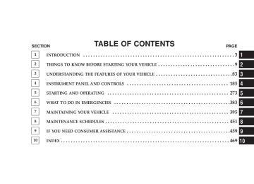
CONTENTS
m If Your Engine Overheats . . . . . . . . . . . . . . . . . 384
m Jacking And Tire Changing . . . . . . . . . . . . . . . . 385
N Jack Location . . . . . . . . . . . . . . . . . . . . . . . . 385
N Spare Tire Stowage . . . . . . . . . . . . . . . . . . . . 386
N Spare Tire Removal . . . . . . . . . . . . . . . . . . . . 386N Preparations For Jacking . . . . . . . . . . . . . . . . 387
N Jacking Instructions . . . . . . . . . . . . . . . . . . . . 388
m Jump Starting . . . . . . . . . . . . . . . . . . . . . . . . . 390
m Towing A Disabled Vehicle . . . . . . . . . . . . . . . . 393 6384 WHAT TO DO IN EMERGENCIES
IF YOUR ENGINE OVERHEATS In any of the following situations, you can reduce the potential for overheating by taking the appropriate ac- tion. † On the highways — Slow down. † In city traffic — While stopped, put transmission in N
(Neutral), but do not increase engine idle speed.
NOTE: There are steps that you can take to slow down an impending overheat condition. If your air conditioner is on, turn it off. The air conditioning system adds heat to the engine cooling system and turning off the A/C removes this heat. You can also turn the Temperature Control to maximum heat, the Mode Control to floor, and the Fan Control to High. This allows the heater core to act as a supplement to the radiator and aids in removing heat from the engine cooling system.
CAUTION!
Driving with a hot cooling system could damage your vehicle. If the temperature gauge reads “H,” pull over and stop the vehicle. Idle the vehicle with the air conditioner turned off until the pointer drops back into the normal range. If the pointer remains on the “H,” and you hear continuous chimes, turn the engine off immediately, and call for service.
JACKING AND TIRE CHANGING
WARNING!
† Getting under a jacked-up vehicle is dangerous. The vehicle could slip off the jack and fall on you. You could be crushed. Never get any part of your body under a vehicle that is on a jack. If you need to get under a raised vehicle, take it to a service center where it can be raised on a lift. † The jack is designed to use as a tool for changing tires only. The jack should not be used to lift the vehicle for service purposes. The vehicle should be jacked on a firm level surface only. Avoid ice or slippery areas.
WHAT TO DO IN EMERGENCIES 385
Jack Location The scissor-type jack and tire changing tools are located in the cargo compartment behind a trim cover on the left rear trim panel. The latch is located at the bottom of the trim cover.
Jack Storage Location
386 WHAT TO DO IN EMERGENCIES
Spare Tire Stowage The spare tire is stowed underneath the rear of the vehicle and is held in place by a cable winch mechanism. Spare Tire Removal Fit the jack handle extension over the drive nut. Use the Lug Wrench to rotate the nut counter clockwise until the spare is on the ground with enough slack in the cable to allow you to pull the tire out from under the vehicle.
Lowering/Raising Spare Tire
CAUTION!
The winch mechanism is designed for use with the jack extension tube only. Use of an air wrench or other power tools is not recommended and they can damage the winch.
When the spare is clear, tilt the retainer at the end of the cable, and pull it through the center of the wheel. Preparations For Jacking † Park the vehicle on a firm level surface as far from the edge of the roadway as possible. Avoid icy or slippery areas. † Set the parking brake and place the gear selector in PARK (automatic transmission) or REVERSE (manual transmission).
† Turn the ignition to the LOCK position.
WHAT TO DO IN EMERGENCIES 387
WARNING!
Do not attempt to change a tire on the side of the vehicle close to moving traffic. Pull far enough off the road to avoid being hit when operating the jack or changing the wheel.
† Turn on the Hazard Warning Flasher.
† Block both the front and rear of the wheel diagonally oppo- site of the jacking position. For example, if changing the right front tire, block the left rear wheel. † Passengers should not remain in the vehicle when the
vehicle is being jacked.
388 WHAT TO DO IN EMERGENCIES
Jacking Instructions
1. Remove spare tire. 2. Loosen (but do not remove) the wheel lug nuts by turning them to the left one turn while the wheel is still on the ground. 3. Remove jack and tools from mounting bracket. As- semble the tools by connecting the driver to the exten- sion, and then to the lug wrench. 4. Locate the jack as shown. For the front tires, place it in the notch on the body weld seam behind wheel to be changed. For the rear tires, place it under the axle by the wheel to be changed. Position the jack handle on the jack. Do not raise the vehicle until you are sure the jack is fully engaged.
Front Jacking Location
WHAT TO DO IN EMERGENCIES 389
WARNING!
Raising the vehicle higher than necessary can make the vehicle less stable and cause an accident. It could slip off the jack and hurt someone near it. Raise the vehicle only enough to remove the tire.
6. Remove the lug nuts and wheel. 7. Position the spare wheel/tire on the vehicle and install lug nuts with cone-shaped end toward wheel. Lightly tighten the nuts. To avoid the risk of forcing the vehicle off the jack, do not tighten the nuts fully until the vehicle has been lowered. 8. Lower the vehicle by turning the jack screw to the left, and remove the jack and wheel blocks. 9. Finish tightening the lug nuts. Push down on the wrench while tightening for increased leverage. Alternate
Rear Jacking Location
5. Raise the vehicle by turning the jack screw to the right. Raise the vehicle only until the tire just clears the surface and enough clearance is obtained to install the spare tire. Minimum tire lift provides maximum stability.
390 WHAT TO DO IN EMERGENCIES
nuts until each nut has been tightened twice. Correct wheel nut tightness is 130 N·m (95 ft. lbs). If in doubt about the correct tightness, have them checked with a torque wrench by your authorized dealer or at a service station. 10. Lower the jack to it’s fully closed position.
WARNING!
A loose tire or jack, thrown forward in a collision or hard stop could endanger the occupants of the ve- hicle. Always stow the jack parts and the spare tire in the places provided.
11. Secure the tire, jack, and tools in their proper loca- tions.
JUMP STARTING
WARNING!
† Take care to avoid the radiator cooling fan whenever the hood is raised. It can start anytime the ignition switch is on. You can be hurt by the fan. † Do not attempt to push or tow your vehicle to get it started. Vehicles equipped with an automatic transmission cannot be started this way. Unburned fuel could enter the catalytic converter and once the engine has started, ignite and damage the converter and vehicle. If the vehicle has a discharged battery, booster cables may be used to obtain a start from another vehicle. This type of start can be dangerous if done improperly, so follow this procedure carefully. † Battery fluid is a corrosive acid solution; do not allow battery fluid to contact eyes, skin, or clothing. Don’t lean over battery when attaching clamps or allow the clamps to touch each other. If acid splashes in eyes or on skin, flush contaminated area immediately with large quantities of water. † A battery generates hydrogen gas, which is flammable and explo- † Do not use a booster battery or any other booster source with an
sive. Keep flame or spark away from the vent holes.
output that exceeds 12 volts.
1. Wear eye protection and remove all metal jewelry such as watchbands or bracelets that might make an unin- tended electrical contact. 2. When boosting from a battery in another vehicle, park that vehicle within booster cable reach, but without allowing the vehicles to touch.
WARNING!
Do not permit vehicles to touch each other as this could establish a ground connection and personal injury could result.
WHAT TO DO IN EMERGENCIES 391
3. Set the parking brake, place the automatic transmis- sion in PARK (or NEUTRAL for manual transmission), and turn the ignition OFF for both vehicles. 4. Turn OFF the heater, radio and all unnecessary elec- trical loads. 5. Connect one end of the jumper cable to the positive battery post. Connect the other end of the same cable to the positive terminal of the booster battery. 6. Connect the other cable, first to the negative terminal of the booster battery and then to the engine ground of the vehicle with the discharged battery. Make sure you have a good contact on the engine ground.
392 WHAT TO DO IN EMERGENCIES
WARNING!
or towing.
† You should not try to start your vehicle by pushing † Do not connect the cable to the negative post of the discharge battery. The resulting electrical spark could cause the battery to explode. † During cold weather when temperatures are be- low freezing point, electrolyte in a discharged battery may freeze. Do not attempt jump-starting because the battery could rupture or explode. The battery temperature must be brought up above freezing point before attempting jump-start.
7. If the vehicle is equipped with Sentry Key Immobi- lizer, turn the ignition switch to the ON position for 3
seconds before moving the ignition switch to the START position. 8. Start the engine in the vehicle that has the booster battery, let the engine idle a few minutes, and then start the engine in the vehicle with the discharged battery. 9. When removing the jumper cables, reverse the above sequence exactly. Be careful of the moving belts and fan.WARNING!
Any procedure other than above could result in: 1. Personal injury caused by electrolyte squirting out the battery vent; 2. Personal injury or property damage due to battery explosion; 3. Damage to charging system of booster vehicle or of immobilized vehicle.
WHAT TO DO IN EMERGENCIES 393
TOWING A DISABLED VEHICLE Proper towing or lifting equipment is required to prevent damage to your vehicle. Use of safety chains is recom- mended. Attach towing device to main structural mem- bers of the vehicle — not to bumpers or associated brackets. State and local laws applying to vehicles under tow must be observed.
394 WHAT TO DO IN EMERGENCIES
TOWING METHOD
NOTE: The transmission & transfer case must be in “N” Neutral under any towing configuration. Model
Flat Towing (all four wheels on the ground)
Front Wheels Raised, Rear Wheels on the Ground
Rear Wheels Raised, Front Wheels on the Ground
2 Wheel Drive
Rear driveshaft re- moved
4 Wheel Drive
Yes
Speed < 30 mph (48
km/h) & distance < 15 miles (24 km) Not RecommendedSpeed < 30 mph (48
km/h) & distance < 15 miles (24 km) Not RecommendedFlat Bed Towing (Recommended for speeds > 30 mph (48
km/h) & distances > 15 miles (24 km) and/or when using a vehicle trailer [All four wheels sus- pended off the ground]) All four wheels sus- pended off the ground All four wheels sus- pended off the groundMAINTAINING YOUR VEHICLE
CONTENTS
m 3.7L Engine Compartment . . . . . . . . . . . . . . . . 398
m Onboard Diagnostic System — OBD II . . . . . . . . 399
N Loose Fuel Filler Cap Message . . . . . . . . . . . . 400m Emissions Inspection And Maintenance
Programs
. . . . . . . . . . . . . . . . . . . . . . . . . . . . 400
m Replacement Parts . . . . . . . . . . . . . . . . . . . . . . 402
m Dealer Service . . . . . . . . . . . . . . . . . . . . . . . . . 402
m Maintenance Procedures . . . . . . . . . . . . . . . . . . 402
. . . . . . . . . . . . . . . . . . . . . . . . . . 403N Engine Oil
N Engine Oil Filter . . . . . . . . . . . . . . . . . . . . . . 405
N Drive Belts — Check Condition And Tension . . 406
N Spark Plugs . . . . . . . . . . . . . . . . . . . . . . . . . 406
N Engine Air Cleaner Filter . . . . . . . . . . . . . . . . 406
N Fuel Filter . . . . . . . . . . . . . . . . . . . . . . . . . . 407
N Catalytic Converter . . . . . . . . . . . . . . . . . . . . 407
N Crankcase Emission Control System . . . . . . . . 409
N Maintenance-Free Battery . . . . . . . . . . . . . . . . 409
N Air Conditioner Maintenance . . . . . . . . . . . . . 411396 MAINTAINING YOUR VEHICLE
N A/C Air Filter — If Equipped . . . . . . . . . . . . 412
N Power Steering — Fluid Check . . . . . . . . . . . . 412
N Driveline And Steering ComponentLubrication . . . . . . . . . . . . . . . . . . . . . . . . . . 413
N Body Lubrication . . . . . . . . . . . . . . . . . . . . . 413
N Windshield Wiper Blades . . . . . . . . . . . . . . . . 413
N Windshield & Rear Window Washers . . . . . . . 414
N Exhaust System . . . . . . . . . . . . . . . . . . . . . . 415
N Cooling System . . . . . . . . . . . . . . . . . . . . . . . 416
N Hoses And Vacuum/Vapor Harnesses . . . . . . . 421
N Fuel System . . . . . . . . . . . . . . . . . . . . . . . . . 421
N Brake System . . . . . . . . . . . . . . . . . . . . . . . . 422
N Clutch Hydraulic System — ManualTransmission (If Equipped)
. . . . . . . . . . . . . . 424
N Automatic Transmission . . . . . . . . . . . . . . . . 425
N Manual Transmission — If Equipped . . . . . . . 426
N Transfer Case . . . . . . . . . . . . . . . . . . . . . . . . 426
N Front/Rear Axle Fluid . . . . . . . . . . . . . . . . . . 428
N Appearance Care And Protection FromCorrosion . . . . . . . . . . . . . . . . . . . . . . . . . . . 428
m Sky Slidert Top Care . . . . . . . . . . . . . . . . . . . . 434
N Washing . . . . . . . . . . . . . . . . . . . . . . . . . . . . 434
N General Cleaning . . . . . . . . . . . . . . . . . . . . . 434
N Additional Cleaning Procedure . . . . . . . . . . . . 435
N Protection . . . . . . . . . . . . . . . . . . . . . . . . . . . 435
N Weather Strip Care . . . . . . . . . . . . . . . . . . . . 436
. . . . . . . . . . . 436m Fuses (Integrated Power Module)
m Replacement Light Bulbs m Bulb Replacement
. . . . . . . . . . . . . . . . . 443
. . . . . . . . . . . . . . . . . . . . . . 443
N Headlight . . . . . . . . . . . . . . . . . . . . . . . . . . . 443
N Front Turn Signal And Front Side MarkerLights . . . . . . . . . . . . . . . . . . . . . . . . . . . . . 444
. . . . . . . . . . . . . . . . . . . . . . 445N Front Fog Light
MAINTAINING YOUR VEHICLE 397
N Rear Tail/Stop, Turn Signal, And Back-Up
Lights . . . . . . . . . . . . . . . . . . . . . . . . . . . . . 445
m Fluid Capacities . . . . . . . . . . . . . . . . . . . . . . . . 447
m Fluids, Lubricants, And Genuine Parts . . . . . . . . 448
N Engine . . . . . . . . . . . . . . . . . . . . . . . . . . . . . 448
N Chassis . . . . . . . . . . . . . . . . . . . . . . . . . . . . 449398 MAINTAINING YOUR VEHICLE
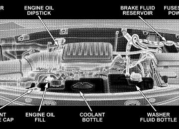
3.7L ENGINE COMPARTMENT
ONBOARD DIAGNOSTIC SYSTEM — OBD II Your vehicle is equipped with a sophisticated onboard diagnostic system called OBD II. This system monitors the performance of the emissions, engine, and automatic transmission control systems. When these systems are operating properly, your vehicle will provide excellent performance and fuel economy, as well as engine emis- sions well within current government regulations. If any of these systems require service, the OBD II system will turn on the “Malfunction Indicator Light.” It will also store diagnostic codes and other information to assist your service technician in making repairs. Al- though your vehicle will usually be drivable and not need towing, see your dealer for service as soon as possible.
MAINTAINING YOUR VEHICLE 399
CAUTION!
† Prolonged driving with the “Malfunction Indica- tor Light” on could cause further damage to the emission control system. It could also affect fuel economy and driveability. The vehicle must be serviced before any emissions tests can be per- formed. † If the “Malfunction Indicator Light” is flashing while the engine is running, severe catalytic con- verter damage and power loss will soon occur. Immediate service is required.
400 MAINTAINING YOUR VEHICLE
Loose Fuel Filler Cap Message If the vehicle diagnostic system determines that the fuel filler cap in loose, improperly installed, or damaged, a “gASCAP” message will display in the instrument clus- ter. Tighten the gas cap until a “clicking” sound is heard. This is an indication that the gas cap is properly tight- ened. Press the trip odometer reset button to turn off the message. If the problem persists, the message will appear the next time the vehicle is started. This might indicate a damaged cap. If the problem is detected twice in a row, the system will turn on the Malfunction Indicator Light (MIL). Resolving the problem will turn the MIL light off.
EMISSIONS INSPECTION AND MAINTENANCE PROGRAMS In some localities, it may be a legal requirement to pass an inspection of your vehicle’s emissions control system. Failure to pass could prevent vehicle registration.
For states, which have an I/M (Inspection and Maintenance) requirement, this check verifies the following: the MIL (Malfunction Indicator Light) is functioning and is not on when the engine is running, and that the OBD (On Board Diagnostic) system is ready for testing. Normally, the OBD system will be ready. The OBD system may not be ready if your vehicle was recently serviced, if you recently had a dead battery, or a battery replacement. If the OBD system should be determined not ready for the I/M test, your vehicle may fail the test. Your vehicle has a simple ignition key actuated test, which you can use prior to going to the test station. To check if your vehicle’s OBD system is ready, you must do the following: 1. Insert your ignition key into the ignition switch.
2. Turn the ignition to the ON position, but do not crank or start the engine. 3. If you crank or start the engine, you will have to start this test over. 4. As soon as you turn your key to the ON position, you will see your MIL symbol come on as part of a normal bulb check. 5. Approximately 15 seconds later, one of two things will happen:
a. The MIL will flash for about 10 seconds and then return to being fully illuminated until you turn off the ignition key or start the engine. This means that your vehicle’s OBD system is not ready and you should not proceed to the I/M station.
MAINTAINING YOUR VEHICLE 401
b. The MIL will not flash at all and will remain fully illuminated until you turn off the ignition key or start the engine. This means that your vehicle’s OBD system is ready and you can proceed to the I/M station.
If your OBD system is not ready, you should see your authorized dealer or repair facility. If your vehicle was recently serviced or had a battery failure or replacement, you may need to do nothing more than drive your vehicle as you normally would in order for your OBD system to update. A recheck with the above test routine may then indicate that the system is now ready. Regardless of whether your vehicle’s OBD system is ready or not ready, if the MIL symbol is illuminated during normal vehicle operation, you should have your vehicle serviced before going to the I/M station. The I/M station can fail your vehicle because the MIL symbol is on with the engine running.
402 MAINTAINING YOUR VEHICLE
REPLACEMENT PARTS Use of genuine Mopart parts for normal/scheduled maintenance and repairs is highly recommended to in- sure the designed performance. Damage or failures caused by the use of non-Mopart parts for maintenance and repairs will not be covered by the manufacturer’s warranty.
DEALER SERVICE Your dealer has the qualified service personnel, special tools, and equipment to perform all service operations in an expert manner. Service Manuals are available which include detailed service information for your vehicle. Refer to these manuals before attempting any procedure yourself. NOTE: systems can result against you.
Intentional tampering with emissions control in civil penalties being assessed
WARNING!
You can be badly injured working on or around a motor vehicle. Only do service work for which you have the knowledge and the proper equipment. If you have any doubt about your ability to perform a service job, take your vehicle to a competent mechanic.
MAINTENANCE PROCEDURES The pages that follow contain the required maintenance services determined by the engineers who designed your vehicle. Besides the maintenance items for which there are fixed maintenance intervals, there are other items that should operate satisfactorily without periodic maintenance. However, if a malfunction of these items does occur, it could adversely affect the engine or vehicle performance.
These items should be inspected if a malfunction is observed or suspected. Engine Oil
Checking Oil Level To assure proper engine lubrication, the engine oil must be maintained at the correct level. The best time to check the engine oil level is about 5
minutes after a fully warmed up engine is shut off or before starting the engine after it has sat overnight. Checking the oil while the vehicle is on level ground will improve the accuracy of the oil level readings. Always maintain the oil level within the SAFE zone on the dipstick. Adding one quart of oil when the reading is at the bottom of the SAFE zone will result in a reading at the top of the safe zone on these engines.MAINTAINING YOUR VEHICLE 403
CAUTION!
Do not overfill the engine. Overfilling the engine will cause oil aeration, which can lead to loss of oil pressure and an increase in oil temperature. This could damage your engine. Also, be sure the oil fill cap is replaced and tightened after adding oil.
404 MAINTAINING YOUR VEHICLE
Change Engine Oil The oil change indicator system will remind you that it is time to take your vehicle in for scheduled maintenance. Refer to “Maintenance Schedule” in Section 8 of this manual for information on this system. NOTE: Under no circumstances should oil change intervals exceed 6,000 miles (10 000 km) or 6 months, whichever occurs first.
Engine Oil Selection For best performance and maximum protection under all types of operating conditions, the manufacturer recom- mends engine oils that are API Certified and meet the requirements of DaimlerChrysler Material Standard MS- 6395.
American Petroleum Institute (API) Engine Oil Identification Symbol
This symbol means that the oil has been certified by the American Petroleum Institute (API). The manufacturer only recommends API Certified engine oils.
Engine Oil Viscosity SAE 5W-20 engine oil is recommended for all operating temperatures. This engine oil improves low temperature starting and vehicle fuel economy. The engine oil filler cap also shows the recommended engine oil viscosity for your engine. For information on engine oil filler cap location, refer to the “Engine Com- partment” illustration in this section.
Lubricants, which do not have both, the engine oil certification mark and the correct SAE viscosity grade number should not be used. Synthetic Engine Oils You may use synthetic engine oils provided the recom- mended oil quality requirements are met, and the recom- mended maintenance intervals for oil and filter changes are followed. Materials Added to Engine Oil The manufacturer strongly recommends against the ad- dition of any additives (other than leak detection dyes) to the engine oil. Engine oil is an engineered product and its performance may be impaired by supplemental addi- tives.
MAINTAINING YOUR VEHICLE 405
Disposing of Used Engine Oil and Oil Filters Care should be taken in disposing of used engine oil and oil filters from your vehicle. Used oil and oil filters, indiscriminately discarded, can present a problem to the environment. Contact your dealer, service station, or governmental agency for advice on how and where used oil and oil filters can be safely discarded in your area. Engine Oil Filter The engine oil filter should be replaced at every engine oil change. Engine Oil Filter Selection All of this manufacturer’s engines have a full-flow type disposable oil filter. Use a filter of this type for replace- ment. The quality of replacement filters varies consider- ably. Only high quality filters should be used to assure most efficient service. Mopart Engine Oil Filters are high quality oil filters and are recommended.
406 MAINTAINING YOUR VEHICLE
Drive Belts — Check Condition and Tension Belt tension is controlled by means of an automatic tensioner. Therefore, no belt tension adjustments are required. However, belt and belt tensioner condition should be inspected periodically and replaced if re- quired. Improper belt tension can cause belt slippage and failure. Low generator belt tension can cause battery failure. Inspect belts for evidence of cuts, cracks, glazing, or frayed cords and replaced if there is indication of dam- age, which could result in belt failure. Also, check belt routing to make sure there is no interference between the belts and other engine components. See your authorized dealer for service.
Spark Plugs Spark plugs must fire properly to assure engine perfor- mance and emission control. New plugs should be in- stalled at the specified mileage. The entire set should be replaced if there is any malfunction due to a faulty spark plug. Malfunctioning spark plugs can damage the cata- lytic converter. Refer to “Fluids, Lubricants, and Genuine Parts” in this section for the proper type of spark plug for use in your vehicle. Engine Air Cleaner Filter Refer to the “Maintenance Schedule” in Section 8 of this manual for engine air cleaner filter maintenance inter- vals. NOTE: Be sure to follow the “dusty or off-road condi- tions” maintenance interval if applicable.
WARNING!
The air induction system (air cleaner, hoses, etc) can provide a measure of protection in the case of engine backfire. Do not remove the air induction system (air cleaner, hoses, etc) unless such removal is necessary for repair or maintenance. Make sure that no one is near the engine compartment before starting the vehicle with the air induction system (air cleaner, hoses, etc) removed. Failure to do so can result in serious personal injury.
MAINTAINING YOUR VEHICLE 407
Fuel Filter A plugged fuel filter can cause stalling, limit the speed at which a vehicle can be driven or cause hard starting. Should an excessive amount of dirt accumulate in the fuel tank, frequent filter replacement may be necessary. See your authorized dealer for service. Catalytic Converter The catalytic converter requires the use of unleaded fuel only. Leaded gasoline will destroy the effectiveness of the catalyst as an emission control device. Under normal operating conditions, the catalytic con- verter will not require maintenance. However, it is im- portant to keep the engine properly tuned to assure proper catalyst operation and prevent possible catalyst damage.
408 MAINTAINING YOUR VEHICLE
CAUTION!
WARNING!