- 2008 Jeep Grand Cherokee SRT8 Owners Manuals
- Jeep Grand Cherokee SRT8 Owners Manuals
- 2012 Jeep Grand Cherokee SRT8 Owners Manuals
- Jeep Grand Cherokee SRT8 Owners Manuals
- 2010 Jeep Grand Cherokee SRT8 Owners Manuals
- Jeep Grand Cherokee SRT8 Owners Manuals
- 2013 Jeep Grand Cherokee SRT8 Owners Manuals
- Jeep Grand Cherokee SRT8 Owners Manuals
- 2009 Jeep Grand Cherokee SRT8 Owners Manuals
- Jeep Grand Cherokee SRT8 Owners Manuals
- 2006 Jeep Grand Cherokee SRT8 Owners Manuals
- Jeep Grand Cherokee SRT8 Owners Manuals
- 2007 Jeep Grand Cherokee SRT8 Owners Manuals
- Jeep Grand Cherokee SRT8 Owners Manuals
- Download PDF Manual
-
rewind through the current audio track or video chapter. In menu modes use to navigate in the menu. 18. ENTER – Press to select the highlighted option in a menu. 19. 䉱 / NEXT – In radio modes, press to select to the next station. In disc modes, press to advance to the next audio track or video chapter. In menu modes, use to navigate in the menu.
Remote Control Storage The video screen(s) come with a built in storage compart- ment for the remote control which is accessible when the screen is opened. To remove the remote, use your index finger to pull and rotate the remote towards you. Do not try to pull the remote straight down as it will be very difficult to remove. To return the remote back into its storage area, insert one long edge of the remote into the two retaining clips first, and then rotate the remote back up into the other two retaining clips until it snaps back into position.
UNDERSTANDING YOUR INSTRUMENT PANEL 371
vehicle is not equipped with a DVD player, follow the radio’s instructions to turn Video Lock on. The radio and the video screen(s) indicate when Video Lock is active. • Pressing the Video Lock again or turning the ignition OFF turns Video Lock OFF and allows remote control operation of the VES™. Replacing The Batteries The remote control requires two AAA batteries for op- eration. To replace the batteries: • Locate the battery compartment on the back of the • Replace the batteries, making sure to orient them according to the polarity diagram shown. • Replace the battery compartment cover.remote, then slide the battery cover downward.
The Remote Control Storage
Locking The Remote Control All remote control functionality can be disabled as a parental control feature. • To disable the Remote Control from making any changes, press the Video Lock button add follow the radio’s instructions (select menu, rear ves, lock). If the
372 UNDERSTANDING YOUR INSTRUMENT PANEL Headphones Operation The headphones receive two separate channels of audio using an infrared transmitter from the video screen. Front seat occupants receive some headphone audio coverage to allow them to adjust the headphone volume for the young rear seat occupants that may not be able to do so for themselves. If no audio is heard after increasing the volume control, verify that the screen is turned on and in the down position and that the channel is not muted and the headphone channel selector switch is on the desired channel. If audio is still not heard, check that fully charged batteries are installed in the headphones.
1. Volume Control 2. Power Button 3. Channel Selection Switch 4. Power Indicator
Controls The headphone power indicator and controls are located on the right ear cup. NOTE: The rear video system must be turned on before sound can be heard from the headphones. To conserve battery life, the headphones will automatically turn off approximately three minutes after the rear video system is turned off. Changing the Audio Mode for Headphones 1. Ensure the Remote Control channel/screen selector switch is in the same position as the headphone selector switch.. NOTE: • When both switches are on Channel 1, the Remote is controlling Channel 1 and the headphones are tuned to the audio of the VES™ Channel 1.
UNDERSTANDING YOUR INSTRUMENT PANEL 373
• When both switches are on Channel 2, the Remote is controlling Channel 2 and the headphones are tuned to the audio of the VES™ Channel 2.
2. Press the MODE button on the remote control. 3. If the video screen is displaying a video source (such as a DVD Video), pressing STATUS shows the status on a popup banner at the bottom of the screen. Pressing the MODE button will advance to the next mode. When the mode is in an audio only source (such as FM), the Mode Selection menu appears on screen. 4. When the Mode Selection menu appears on screen, use the cursor buttons on the remote control to navigate to the available modes and press the ENTER button to select the new mode. 5. To cancel out of the Mode Selection menu, press the BACK button on the remote control.
374 UNDERSTANDING YOUR INSTRUMENT PANEL Replacing The Batteries Each set of headphones requires two AAA batteries for operation. To replace the batteries: • Locate the battery compartment on the left ear cup of the headphones, and then slide the battery cover downward. • Replace the batteries, making sure to orient them according to the polarity diagram shown. • Replace the battery compartment cover. Unwired姞 Stereo Headphone Lifetime Limited Warranty Who Does This Warranty Cover? This warranty covers the initial user or purchaser (⬙you⬙ or ⬙your⬙) of this particular Unwired Technology LLC (⬙Unwired⬙) wire- less headphone (⬙Product⬙). The warranty is not transfer- able.
How Long Does The Coverage Last? This warranty lasts as long as you own the Product. What Does This Warranty Cover? Except as specified below, this warranty covers any Product that in normal use is defective in workmanship or materials. What Does This Warranty Not Cover? This warranty does not cover any damage or defect that results from misuse, abuse or modification of the Product other than by Unwired. Foam earpieces, which will wear over time through normal use, are specifically not covered (replace- ment foam is available for a nominal charge). UNWIRED TECHNOLOGY IS NOT LIABLE FOR ANY INJURIES OR DAMAGES TO PERSONS OR PROPERTY RESULT- ING FROM THE USE OF, OR ANY FAILURE OR DE- FECT IN, THE PRODUCT, NOR IS UNWIRED LIABLE FOR ANY GENERAL, SPECIAL, DIRECT, INDIRECT, INCIDENTAL, CONSEQUENTIAL, EXEMPLARY, PU- NITIVE OR OTHER DAMAGES OF ANY KIND OR
NATURE WHATSOEVER. Some states and jurisdictions may not allow the exclusion or limitation of incidental or consequential damages, so the above limitation may not apply to you. This warranty gives you specific legal rights. You may also have other rights, which vary from jurisdiction to jurisdiction. What Will Unwired威 Do? Unwired威, at its option, will repair or replace any defective Product. Unwired威 re- serves the right to replace any discontinued Product with a comparable model. THIS WARRANTY IS THE SOLE WARRANTY FOR THIS PRODUCT, SETS FORTH YOUR EXCLUSIVE REMEDY REGARDING DEFECTIVE PRODUCTS, AND IS IN LIEU OF ALL OTHER WAR- RANTIES (EXPRESS OR IMPLIED), INCLUDING ANY WARRANTY OR MERCHANTABILITY OR FITNESS FOR A PARTICULAR PURPOSE. If you have any questions or comments regarding your Unwired威 wireless headphones, please phone 1-888-293- 3332 or email [email protected].
UNDERSTANDING YOUR INSTRUMENT PANEL 375
You may register your Unwired威 wireless headphones online at www.unwiredtechnology.com or by phone at 1-888-293-3332. System InformationShared Modes This allows the VES™ to output radio sources to the headphones and the radio to output VES™ sources to the vehicle speakers. When the radio and VES™ channel 1 or 2 are in the same (shared) mode, a VES™ icon will be visible on the radio’s display for that channel, and the shared icon will be visible on the VES™ screen. When in shared mode, the same audio source is heard in the shared headphone channel 1 or channel 2. If the radio functions (FM, AM, or SAT) are in the shared mode with the VES™, only the radio is able to control the radio functions. In this case, VES™ can share the radio mode, but not change stations until the radio mode is changed to a mode that is different from the VES™
376 UNDERSTANDING YOUR INSTRUMENT PANEL selected radio mode. When shared, the radio has priority over the VES™ or all radio modes (FM, AM). The VES™ has the ability to switch tuner (AM/FM), SEEK, SCAN, TUNE, and recall presets in radio modes as long as it is not in shared mode. When in shared disc both the radio and the VES™ have control of the video functions. The VES™ has the ability to control the following video modes: 1. CD: Ability to Fast Forward, Rewind, Scan, and Track Up/Down. 2. CD Changer (in radio): Ability to Disk Up/Down and program all listed CD controls (Fast Forward, Rewind, Scan, and Track Up/Down). The VES™ can even control radio modes or video modes while the radio is turned off. The VES™ can access the radio modes or disc modes by navigating to those modes on the VES™ and activating a radio mode or disc mode.
Information Mode Display
Information Mode Video Screen Display
1. Channel 1 Mode 2. Channel 1 Shared Status 3. Channel 1 Audio Only/Mute 4. Channel 2 Mode
5. Channel 2 Shared Status 6. Channel 2 Audio Only/Mute 7. Channel 1 ENTER Button Action 8. Channel 2 ENTER Button Action 9. Clock 10. Video Lock 11. Not Available / Error 12. Disc Changer Status
UNDERSTANDING YOUR INSTRUMENT PANEL 377
Numeric Keypad Menu
Numeric Keypad Menu
378 UNDERSTANDING YOUR INSTRUMENT PANEL When the display for either Channel 1 or Channel 2
shows DIRECT TUNE, pressing the remote control’s ENTER button activates a numeric keypad menu. This screen makes it easy to enter a specific tuner frequency, satellite channel, or track number. To enter the desired digit: 1. Press the remote control’s navigation buttons (䉱, 䉲, 䉴, 䉳) to navigate to the desired digit. 2. When the digit is highlighted, press the remote con- trol’s ENTER button to select the digit. Repeat these steps until all digits are entered. 3. To delete the last digit, navigate to the Del button and press the remote control’s ENTER button. 4. After all of the digits are entered, navigate to the Go button and press the remote control’s ENTER button.Station List Menu
Channel Selection Menu For SIRIUS Backseat TV™
When listening to Satellite audio, pressing the remote control’s MENU button displays a list of all available channels. Navigate this list using the remote control’s navigation buttons (䉱, 䉲) to find the desired station, press the remote control’s ENTER button to tune to that station. To jump through the list more quickly, navigate to the Page Up and Page Down icons on the screen.
Disc Menu
Display Settings
UNDERSTANDING YOUR INSTRUMENT PANEL 379
Disc Menu For CDs
Video Screen Display Settings
When listening to a CD Audio or CD Data disc, pressing the remote control’s MENU button displays a list of all commands which control playback of the disc. Using the options you can activate or cancel Scan play and Random play.
When watching a video source (DVD Video with the disc in Play mode, Aux Video, SIRIUS Backseat TV™, etc.), pressing the remote control’s SETUP button activates the Display Settings menu. These settings control the appear- ance of the video on the screen. The factory default
380 UNDERSTANDING YOUR INSTRUMENT PANEL settings are already set for optimum viewing, so there is no need to change these settings under normal circum- stances. To change the settings, press the remote control’s navi- gation buttons (䉱, 䉲) to select an item, then press the remote control’s navigation buttons (䉴, 䉳) to change the value for the currently selected item. To reset all values back to the original settings, select the Default Settings menu option and press the remote control’s ENTER button. Disc Features control the remote DVD player’s (if equipped) settings of DVD being watched in the remote player. Listening To Audio With The Screen Closed To listen to only audio portion of the channel with the screen closed: • Set the audio to the desired source and channel.
• Close the video screen. • To change the current audio mode, press the remote control’s MODE button. This will automatically select the next available audio mode without using the Mode Select menu. • When the screen is reopened, the video screen will automatically turn back on and show the appropriate display menu or media.
If the screen is closed and there is no audio heard, verify that the headphones are turned on (the ON indicator is illuminated) and the headphone selector switch is on the desired channel. If the headphones are turned on, press the remote control’s power button to turn audio on. If audio is still not heard, check that fully charged batteries are installed in the headphones.
notes about DVD Region Codes)
Disc Formats The VES™ DVD player is capable of playing the follow- ing types of discs (12 mm or 8 mm diameter): • DVD-Video discs (MPEG-2 video compression) (see • DVD-Audio discs (2 channel audio output only) • Audio Compact Discs (CDs) • CD Data discs with MP3 and WMA compressed audio • Video CDs (MPEG-1 video compression) DVD Region Codes The VES™ DVD player and many DVD discs are coded by geographic region. These region codes must match in order for the disc to play. If the region code for the DVD disc does not match the region code for the player, the disc will not play and will be ejected.
format files
UNDERSTANDING YOUR INSTRUMENT PANEL 381
DVD Audio Support When a DVD-Audio disc is inserted in the VES™ DVD player, the DVD-Audio title on the disc is played by default (most DVD-Audio discs also have a Video title, but the Video title is ignored). All multi-channel program material is automatically mixed down to two channels, which may result in a lowered apparent volume level. If you increase the volume level to account for this change in level, remember to lower the volume before changing the disc or to another mode. Recorded Discs The VES™ DVD player will play CD-R and CD-RW discs recorded in CD-Audio or Video-CD format, or as a CD-ROM containing MP3 or WMA files. The player will also play DVD-Video content recorded to a DVD-R or DVD-RW disc. DVD-ROM discs (either pressed or re- corded) are not supported.
closed are playable.
382 UNDERSTANDING YOUR INSTRUMENT PANEL If you record a disc using a personal computer, there may be cases where the VES™ DVD player may not be able to play some or the entire disc, even if it is recorded in a compatible format and is playable on other players. To help avoid playback problems, use the following guide- lines when recording discs. • Open sessions are ignored. Only sessions that are • For multi-session CDs that contain only multiple CD- Audio sessions, the player will renumber the tracks so each track number is unique. • For CD Data (or CD-ROM) discs, always use the ISO-9660 (Level 1 or Level 2), Joliet, or Romeo format. Other formats (such as UDF, HFS, or others) are not supported. • The player recognizes a maximum of 512 files and 99
folders per CD-R and CD-RW disc.
• Mixed media recordable DVD formats will only play
the Video_TS portion of the disc.
If you are still having trouble writing a disc that is playable in the VES™ DVD player, check with the disc recording software publisher for more information about burning playable discs. The recommended method for labeling recordable discs (CD-R, CD-RW, and DVD-R) is with a permanent marker. Do not use adhesive labels as they may separate from the disc, become stuck, and cause permanent damage to the DVD player. Compressed Audio Files (MP3 and WMA) The DVD player is capable of playing MP3 (MPEG-1
Audio Layer 3) and WMA (Windows Media Audio) files from a CD Data disc (usually a CD-R or CD-RW).artist name, track title, album, etc.) are supported.
• The DVD player always uses the file extension to determine the audio format, so MP3 files must always end with the extension ⬙.mp3⬙ or ⬙.MP3⬙ and WMA files must always end with the extension ⬙.wma⬙ or ⬙.WMA⬙. To prevent incorrect playback, do not use these extensions for any other types of files. • For MP3 files, only version 1 ID3 tag data (such as • Any file that is copy protected (such as those down- loaded from many online music stores) will not play. The DVD player will automatically skip the file and begin playing the next available file. • Other compression formats such as AAC, MP3 Pro, Ogg Vorbis, and ATRAC3 will not play. The DVD player will automatically skip the file and begin play- ing the next available file.
UNDERSTANDING YOUR INSTRUMENT PANEL 383
• If you are creating your own files, the recommended fixed bit rate for MP3 files is between 96 and 192Kbps and the recommended fixed bit rate for WMA files is between 64 and 192Kbps. Variable bit rates are also the recommended supported. For both formats, sample rate is either 44.1kHz or 48kHz. • To change the current file, use the remote control’s or DVD player’s 䉱 button to advance to the next file, or the 䉲 button to return to the start of the current or previous file. • To change the current directory, use the remote con-
trol’s PROG Up and Down buttons.
Disc Errors If the DVD player is unable to read the disc, a ⬙Disc Error⬙ message is displayed on the VES™ and Radio displays
Display Other Language Setup
384 UNDERSTANDING YOUR INSTRUMENT PANEL and the disc is automatically ejected. A dirty, damaged, or incompatible disc format are all potential causes for a ⬙Disc Error⬙ message. If a disc has a damaged track which results in audible or visible errors that persists for 2.0 seconds, the DVD player will attempt to continue playing the disc by skipping forward 1.0 to 3.0 seconds at a time. If the end of the disc is reached, the DVD player will return to the beginning of the disc and attempt to play the start of the first track. The DVD player may shut down during extremely hot conditions, such as when the vehicle’s interior tempera- ture is above 120°F. When this occurs, the DVD player will display ⬙VES High Temp⬙ and will shut off the VES™ displays until a safe temperature is reached. This shut- down is necessary to protect the optics of the DVD player.
DVD Player Language Menu
All of the Language settings have a special ⬙Other⬙ setting to accommodate languages other than Japanese or Eng- lish. These languages are selected using a special four- digit code. To enter a new language code, activate the DVD Setup Menu and follow these additional instructions: • Using the remote control Up and Down cursor but- tons, highlight the Language item you want to edit, and then press the remote control ENTER button. • Using the remote control Down cursor button, select the ⬙Other⬙ setting, then press the remote control’s Right cursor button to begin editing the setting. • Using the remote control Up and Down cursor but- tons, select a digit for the current position. After selecting the digit, press the remote control’s Right cursor button to select the next digit. Repeat this digit selection sequence for all four digits.
UNDERSTANDING YOUR INSTRUMENT PANEL 385
• When the entire four-digit code is entered, press the remote control’s ENTER button. If the language code is not valid, the numbers all change back to ⬙*⬙. If the digits are visible after this step, then the language code is valid.
Here is an abbreviated list of language codes. For more language codes, please contact the dealer where the vehicle was purchased. Language Dutch German Portuguese Rating and Password Setup The Rating and Password settings work together to control the types of DVDs that your family watches. Most DVD-Video discs have a rating (from 1 to 8) assigned to
Language French Italian Spanish
Code 1517
1819
1418Code 2311
1304
2519The default rating is Level 8 (play all discs without a password) and the default password is 0000.
386 UNDERSTANDING YOUR INSTRUMENT PANEL them where lower numbers are designated for all audi- ences and higher numbers are designated for more adult audiences. When a DVD-Video disc is loaded, its rating is compared to the setting in the DVD player. If the rating of the disc is higher than the setting in the player, a Password screen is displayed. In order to watch the disc, the rear passen- ger must enter the correct password using the password entry method described below. To play all discs without requiring a password, set the DVD player’s rating to Level 8. Setting the rating to Level 1 always requires the password to play any DVD disc. Not all DVD discs encode a Rating, so it is still possible that discs designed for adult audiences can still play without requiring a password.
DVD Password Entry
tons, select the Rating tab.
remote control’s ENTER button.
To set the password, activate the DVD Setup Menu and follow these additional instructions: • Using the remote control Left and Right cursor but- • Highlight ⬙Change Password⬙, and then press the • Enter the current password. Select a digit, use the remote control Up and Down cursor buttons to set the value for the current digit, and then press the remote control’s Right cursor button to select the next digit. Repeat this digit selection sequence for all four digits. • After the four-digit password is entered, press the remote control’s ENTER button. If the password is correct, the set password screen is displayed. • Using the remote control’s Up and Down cursor buttons to set the value for the current digit and the remote control’s Right cursor button to select digits, enter the new password.
UNDERSTANDING YOUR INSTRUMENT PANEL 387
• After the four-digit password is entered, press the remote control’s ENTER button to accept the change.
DVD Player Level Menu
control’s ENTER button.
buttons, select the Rating tab.
388 UNDERSTANDING YOUR INSTRUMENT PANEL To set the rating, activate the DVD Setup Menu and follow these additional instructions: • Using the remote control’s Left and Right cursor • Highlight ⬙Change Rating⬙, and then press the remote • Enter the current password. Select a digit, use the remote control’s Up and Down cursor buttons to set the value for the current digit, and then press the remote control’s Right cursor button to select the next digit. Repeat this digit selection sequence for all four digits. • After the four-digit password is entered, press the remote control’s ENTER button. If the password is correct, the Rating Level menu is displayed.
• Using the remote control’s Up and Down cursor buttons, select the new rating level, and then press the remote control’s ENTER button to accept the change.
Product Agreement This product incorporates copyright protection technol- ogy that is protected by U.S. patents and other intellec- tual property rights. Use of this copyright protection technology must be authorized by Macrovision, and is intended for home or other limited viewing uses other- wise authorized by Macrovision. Reverse engineering or disassembly is prohibited.
Dolby威 Digital and MLP Lossless Manufactured under license from Dolby Laboratories. ⬙Dolby⬙, ⬙MLP Lossless⬙, and the double-D symbol are trademarks of Dolby Laboratories. Confidential unpublished works. Copyright 1992-1997 Dolby Laboratories. All right re- served.
General Information This system complies with Part 15 of the FCC Operation is subject to the following two conditions: 1. This device may not cause harmful interference. 2. This device must accept any interference received, including interference that may cause undesired operation.
HARMAN KARDON姞 Logic7姞 HIGH PERFORMANCE MULTICHANNEL SURROUND SOUND SYSTEM WITH DRIVER-SELECTABLE SURROUND (DSS) — IF EQUIPPED Your vehicle is equipped with a Harman Kardon audio system with GreenEdge™ technology that offers superior sound quality, higher Sound Pressure Levels (SPL) and reduced energy consumption. The new system utilizes
UNDERSTANDING YOUR INSTRUMENT PANEL 389
proprietary amplifier and speaker technologies deliver- ing substantial increases in component and system effi- ciency levels. The 12 Channel Class D GreenEdge high efficiency amplifier is governed by a high voltage tracking power supply and drives a 7.3-channel playback architecture. The Harman Kardon audio system offers the ability to choose Logic 7 surround sound for any audio source. The GreenEdge high-efficiency speaker designs ensure the system has higher SPL and a dramatic increase in dy- namic sound quality. The speakers are tuned for maxi- mum efficiency and perfectly matched to the amplifier output stage ensuring state of the art multi-seat surround sound processing. Logic7 multichannel surround-sound technology deliv- ers an immersive, accurate sound-stage to every seating position This surround effect is available for audio from any source - AM/FM/CD/ Satellite Radio or dashboard390 UNDERSTANDING YOUR INSTRUMENT PANEL AUX input; and is activated through the Electronic Vehicle Information Center (EVIC). Refer to “Driver- Selectable Surround Sound (DSS)” under “Electronic Vehicle Information Center (EVIC)” in “Understanding Your Instrument Panel”. Selecting “Audio Surround” through the DSS modes activates the Harman Kardon Logic7 multichannel surround-sound technology in your vehicle. The “Video Surround” mode is described under Driver-Selectable Surround (DSS). The Video Surround Mode will only be available for video media sources (DVDs, Video CDs, or other video media supported by the radio). Some audio will sound better in DSS modes, others in Stereo mode. When in “Audio Surround” mode, balance is set auto- matically. Fader control is available in surround mode but should be set to the center position for optimal surround performance.
STEERING WHEEL AUDIO CONTROLS The remote sound system controls are located on the rear surface of the steering wheel. Reach behind the wheel to access the switches.
Remote Sound System Controls (Back View Of Steering Wheel)
The right-hand control is a rocker-type switch with a pushbutton in the center and controls the volume and mode of the sound system. Pressing the top of the rocker switch will increase the volume, and pressing the bottom of the rocker switch will decrease the volume. Pressing the center button will make the radio switch between the various modes available (AM/FM/SAT/ CD/HDD/AUX/VES, etc.). The left-hand control is a rocker-type switch with a pushbutton in the center. The function of the left-hand control is different depending on which mode you are in. The following describes the left-hand control operation in each mode. Radio Operation Pressing the top of the switch will “Seek” up for the next listenable station and pressing the bottom of the switch will “Seek” down for the next listenable station.
UNDERSTANDING YOUR INSTRUMENT PANEL 391
The button located in the center of the left-hand control will tune to the next preset station that you have pro- grammed in the radio preset pushbutton. CD Player Pressing the top of the switch once will go to the next track on the CD. Pressing the bottom of the switch once will go to the beginning of the current track, or to the beginning of the previous track if it is within one second after the current track begins to play. If you press the switch up or down twice, it plays the second track; three times, it will play the third, etc. The center button on the left side rocker switch has no function for a single-disc CD player. However, when a multiple-disc CD player is equipped on the vehicle, the center button will select the next available CD in the player.392 UNDERSTANDING YOUR INSTRUMENT PANEL CD/DVD DISC MAINTENANCE To keep a CD/DVD in good condition, take the following precautions: 1. Handle the disc by its edge; avoid touching the surface. 2. If the disc is stained, clean the surface with a soft cloth, wiping from center to edge. 3. Do not apply paper or tape to the disc; avoid scratch- ing the disc. 4. Do not use solvents such as benzene, thinner, cleaners, or anti-static sprays. 5. Store the disc in its case after playing. 6. Do not expose the disc to direct sunlight. 7. Do not store the disc where temperatures may become too high.
If you experience difficulty in playing a particu- NOTE: lar disc, it may be damaged (i.e., scratched, reflective coating removed, a hair, moisture or dew on the disc) oversized, or have protection encoding. Try a known good disc before considering disc player service.
RADIO OPERATION AND MOBILE PHONES Under certain conditions, the mobile phone being on in your vehicle can cause erratic or noisy performance from your radio. This condition may be lessened or eliminated by relocating the mobile phone antenna. This condition is not harmful to the radio. If your radio performance does not satisfactorily “clear” by the repositioning of the antenna, it is recommended that the radio volume be turned down or off during mobile phone operation when not using Uconnect™ (if equipped).
CLIMATE CONTROLS The air conditioning and heating system is designed to make you comfortable in all types of weather.
Dual-Zone Automatic Temperature Control (ATC) — If Equipped • The Automatic Temperature Control (ATC) allows both driver and front passenger seat occupants to select individual comfort settings. • When occupants in the vehicle select an Auto mode operation, Auto blower operation is set by using a push button on the control unit and a comfort tem- perature setting by using the temperature up and down buttons. • The system provides set-and-forget operation for op- • The system can be controlled manually, if desired. The ATC system automatically maintains the interior comfort level desired by the driver and passenger.
timum comfort and convenience.
UNDERSTANDING YOUR INSTRUMENT PANEL 393
Automatic Temperature Control (ATC) Panel
1. A/C Button Press and release to change the current Air Conditioning (A/C) setting, the indicator illuminates when A/C is ON. Performing this function will cause the ATC to switch into manual mode.
394 UNDERSTANDING YOUR INSTRUMENT PANEL 2. Recirculation Control Button Press and release to change the current setting, the indicator illuminates when ON. 3. Left Front Seat Occupant Temperature Display This display shows the temperature setting for the left front seat occupant. 4. Mode Display This display shows the current Mode selection (Panel, Bi-Level, Floor, Mix). 5. Blower Control Display This display shows the current Blower speed selection. 6. Right Front Seat Occupant Temperature Display This display shows the temperature setting for the right front seat occupant. 7. Front Defrost Button Press and release to change the current setting, the indicator illuminates when ON. Performing this function
will cause the ATC to switch into manual mode. The blower will engage immediately if the Defrost mode is selected. 8. Passenger Temperature Control Up Button Provides the passenger with independent temperature control. Push the button for warmer temperature set- tings. 9. Passenger Temperature Control Down Button Provides the passenger with independent temperature control. Push the button for cooler temperature settings. 10. Auto Temperature Control Button Controls airflow temperature, distribution, volume, and the amount of air recirculation automatically. Press and release to select. Refer to “Automatic Operation” for more information. Performing this function will cause the ATC to switch between manual mode and automatic modes.
11. Blower Control There are seven blower speeds, the blower speed in- creases as you move the control to the right from the lowest blower setting. Performing this function will cause the ATC to switch into manual mode. 12. Climate Control ON/OFF Button Press and release this button to turn the Climate Control OFF 13. Mode Control Button Press and release to select between Modes (Panel, Bi- Level, Floor, Mix). Performing this function will cause the ATC to switch into manual mode. 14. SYNC Button Press and release to control the temperature setting for both zones from the driver temperature control.
UNDERSTANDING YOUR INSTRUMENT PANEL 395
15. Driver Temperature Control Down Button Provides the driver with independent temperature con- trol. Push the button for cooler temperature settings. 16. Driver Temperature Control Up Button Provides the driver with independent temperature con- trol. Push the button for warmer temperature settings. Automatic Operation 1. Press the AUTO button on the Automatic Temperature Control (ATC) Panel. 2. Next, adjust the temperature you would like the system to maintain by adjusting the driver and front passenger temperature control buttons. Once the desired temperature is displayed, the system will achieve and automatically maintain that comfort level.
396 UNDERSTANDING YOUR INSTRUMENT PANEL 3. When the system is set up for your comfort level, it is not necessary to change the settings. You will experience the greatest efficiency by simply allowing the system to function automatically. NOTE: • It is not necessary to move the temperature settings for cold or hot vehicles. The system automatically adjusts the temperature, mode and fan speed to provide comfort as quickly as possible. • The temperature can be displayed in U.S. or Metric units by selecting the US/M customer-programmable feature. Refer to the “Electronic Vehicle Information Center (EVIC) — Customer-Programmable Features (SETUP)” in this section of the manual.
To provide you with maximum comfort in the Automatic mode, during cold start-ups the blower fan will remain on low until the engine warms up. The blower will increase in speed and transition into Auto mode.
Manual Operation This system offers a full complement of manual override features. NOTE: Each of these features operate independently from each other. If any one feature is controlled manually, temperature control will continue to operate automati- cally.
There are seven fixed blower speeds. Use the outer dial control to regulate the amount of air forced through the system in any mode you select. The blower speed increases as you move the control clockwise and decreases when you move the control counter- clockwise.
Blower Control
The blower fan speed can be set to any fixed speed by adjusting the blower control outer dial. The fan will now operate at a fixed speed until additional speeds are selected. This allows the front occupants to control the volume of air circulated in the vehicle and cancel the Auto mode. The operator can also select the direction of the airflow by selecting one of the following positions. Panel Mode
Air comes from the outlets in the instrument panel. Each of these outlets can be individually adjusted to direct the flow of air. The air vanes of the center outlets and outboard outlets can be moved up and down or side to side to regulate airflow direction. There is a shut off wheel located below the air vanes to shut off or adjust the amount of airflow from these outlets.
UNDERSTANDING YOUR INSTRUMENT PANEL 397
Bi-Level Mode
Air comes from the instrument panel outlets, floor outlets and defrost outlets.
In many temperature positions, the BI-LEVEL NOTE: mode is designed to provide cooler air out of the panel outlets and warmer air from the floor outlets. Floor Mode
Air comes from the floor outlets. A slight amount of air is directed through the defrost and side window
demister outlets. Mix Mode
Air comes from the floor, defrost and side window demist outlets. This mode works best in cold or snowy conditions. It allows you to stay comfortable
while keeping the windshield clear.
398 UNDERSTANDING YOUR INSTRUMENT PANEL Defrost Mode
Air comes from the windshield and side window demist outlets. Use Defrost mode with maximum temperature settings for best windshield and side win- dow defrosting. When the defrost mode is selected, the blower will automatically default to medium-high unless the blower is controlled manually. NOTE: While operating in the other modes, the system will not automatically sense the presence of fog, mist or ice on the windshield. Defrost mode must be manually selected to clear the windshield and side glass. Air Conditioning (A/C) The Air Conditioning (A/C) button allows the operator to manually activate or deactivate the air conditioning system. When in A/C mode and the ATC is set to a cool temperature, dehumidified air flows through the air outlets. If Economy mode is desired, press the A/C button to turn off the A/C mode in the ATC display and deactivate the A/C system.
NOTE: • If the system is in Mix, Floor or Defrost Mode, the A/C can be turned off, but the A/C system shall remain active to prevent fogging of the windows. • If fog or mist appears on the windshield or side glass,
select Defrost mode and increase blower speed.
Recirculation Control
When outside air contains smoke, odors, or high humidity, or if rapid cooling is desired, you may wish to recirculate interior air by pressing the RECIRCULATION control button. Recirculation mode should only be used temporarily. The recirculation LED will illuminate when this button is selected. Push the button a second time to turn off the Recirculation mode LED and allow outside air into the vehicle.
In cold weather, use of Recirculation mode may NOTE: lead to excessive window fogging. The Recirculation mode is not allowed in the Floor/Defrost Mix and Defrost modes to improve window clearing operation. Recirculation will be disabled automatically if these modes are selected. Operating Tips
Window Fogging Windows will fog on the inside when the humidity inside the vehicle is high. This often occurs in mild or cool temperatures when it’s rainy or humid. In most cases, turning the air conditioning (pressing the A/C button) on will clear the fog. Adjust the temperature control, air direction, and blower speed to maintain comfort.
UNDERSTANDING YOUR INSTRUMENT PANEL 399
As the temperature gets colder, it may be necessary to direct air onto the windshield. Adjust the temperature control and blower speed to maintain comfort. Higher blower speeds will reduce fogging. Interior fogging on the windshield can be quickly removed by selecting the DEFROST mode. Regular cleaning of the inside of the windows with a non-filming cleaning solution (vinegar and water works very well) will help prevent contaminates (cigarette smoke, perfumes, etc.) from sticking to the windows. Contaminates increase the rate of window fogging.400 UNDERSTANDING YOUR INSTRUMENT PANEL Summer Operation
In some cases during high temperature trailer NOTE: tow operation the Air Conditioning system performance may be reduced. This is to help protect the engine from overheating during the high load condition. Your air conditioning system is also equipped with an automatic recirculation system. When the system senses a heavy load or high heat conditions, it may use partial Recirculation A/C mode to provide additional comfort.
is
ice,
slush,
free of
Winter Operation When operating the system during the winter months, make sure the air intake, located directly in front of the windshield, snow, or other obstructions. Vacation Storage Anytime you store your vehicle, or keep it out of service (i.e. vacation) for two weeks or more, run the air condi- tioning system at idle for about five minutes in the fresh air and high blower setting. This will ensure adequate system lubrication to minimize the possibility of com- pressor damage when the system is started again.
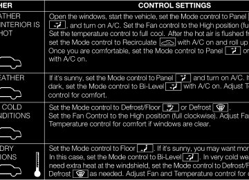
Operating Tips Chart
UNDERSTANDING YOUR INSTRUMENT PANEL 401
STARTING AND OPERATING
CONTENTS
䡵 Starting Procedures . . . . . . . . . . . . . . . . . . . . 407
▫ Automatic Transmission . . . . . . . . . . . . . . . 407
▫ Keyless Enter-N-Go . . . . . . . . . . . . . . . . . . . 408
▫ Normal Starting . . . . . . . . . . . . . . . . . . . . . 409
▫ Extreme Cold Weather(Below –20°F Or ⫺29°C) . . . . . . . . . . . . . . . 411
▫ If Engine Fails To Start . . . . . . . . . . . . . . . . 411
▫ After Starting . . . . . . . . . . . . . . . . . . . . . . . 412䡵 Automatic Transmission . . . . . . . . . . . . . . . . . 413
▫ Key Ignition Park Interlock . . . . . . . . . . . . . 415
▫ Brake/Transmission Shift Interlock System . . 415
▫ Five-Speed Automatic Transmission . . . . . . . 415
▫ Gear Ranges . . . . . . . . . . . . . . . . . . . . . . . . 416
䡵 AutoStick威 . . . . . . . . . . . . . . . . . . . . . . . . . . 421
▫ Operation . . . . . . . . . . . . . . . . . . . . . . . . . 422
䡵 Selec-Track™ . . . . . . . . . . . . . . . . . . . . . . . . 424
▫ Description . . . . . . . . . . . . . . . . . . . . . . . . 424404 STARTING AND OPERATING
䡵 Driving Through Water
▫ Active Damping System . . . . . . . . . . . . . . . 426
. . . . . . . . . . . . . . . . . 426
▫ Flowing/Rising Water . . . . . . . . . . . . . . . . . 427
䡵 Power Steering . . . . . . . . . . . . . . . . . . . . . . . 429
䡵 Parking Brake . . . . . . . . . . . . . . . . . . . . . . . . 430
䡵 Electronic Brake Control System . . . . . . . . . . . 433
▫ Anti-Lock Brake System (ABS) . . . . . . . . . . . 433
▫ Traction Control System (TCS) . . . . . . . . . . . 433
▫ Brake Assist System (BAS) . . . . . . . . . . . . . . 434
▫ Electronic Roll Mitigation (ERM) . . . . . . . . . 435
▫ Electronic Stability Control (ESC) . . . . . . . . . 435
▫ Trailer Sway Control (TSC) . . . . . . . . . . . . . 439▫ ESC Activation/Malfunction Indicator Light
And ESC Off Indicator Light
. . . . . . . . . . . . 440
䡵 Tire Safety Information . . . . . . . . . . . . . . . . . 441
▫ Tire Markings . . . . . . . . . . . . . . . . . . . . . . . 441
▫ Tire Identification Number (TIN) . . . . . . . . . 445
▫ Tire Terminology And Definitions . . . . . . . . . 446
▫ Tire Loading And Tire Pressure . . . . . . . . . . 447
䡵 Tires — General Information . . . . . . . . . . . . . 451
▫ Tire Pressure . . . . . . . . . . . . . . . . . . . . . . . 451
▫ Tire Inflation Pressures . . . . . . . . . . . . . . . . 452
▫ Tire Pressures For High Speed Operation . . . 454
▫ Radial-Ply Tires . . . . . . . . . . . . . . . . . . . . . 454
▫ Spare Tire Matching Original Equipped TireAnd Wheel – If Equipped . . . . . . . . . . . . . . 455
▫ Compact Spare Tire – If Equipped . . . . . . . . 455
▫ Full Size Spare – If Equipped . . . . . . . . . . . . 457
▫ Limited-Use Spare – If Equipped . . . . . . . . . 457
▫ Tire Spinning . . . . . . . . . . . . . . . . . . . . . . . 458
▫ Tread Wear Indicators . . . . . . . . . . . . . . . . . 458
▫ Life Of Tire . . . . . . . . . . . . . . . . . . . . . . . . 459
▫ Replacement Tires . . . . . . . . . . . . . . . . . . . . 459
. . . . . . . . . . . 461
. . . . . . . 462
▫ Premium System . . . . . . . . . . . . . . . . . . . . 464
▫ General Information . . . . . . . . . . . . . . . . . . 468
䡵 Fuel Requirements . . . . . . . . . . . . . . . . . . . . . 469
▫ 6.4L Engine . . . . . . . . . . . . . . . . . . . . . . . . 469䡵 Tire Rotation Recommendations 䡵 Tire Pressure Monitor System (TPMS)
STARTING AND OPERATING 405
▫ Reformulated Gasoline . . . . . . . . . . . . . . . . 469
▫ Gasoline/Oxygenate Blends . . . . . . . . . . . . . 470
▫ E-85 Usage In Non-Flex Fuel Vehicles . . . . . . 470
▫ MMT In Gasoline . . . . . . . . . . . . . . . . . . . . 471
▫ Materials Added To Fuel . . . . . . . . . . . . . . . 471
▫ Fuel System Cautions . . . . . . . . . . . . . . . . . 472
▫ Carbon Monoxide Warnings . . . . . . . . . . . . 473
. . . . . . . . . . . . . . . . . . . . . . . . . 473
▫ Fuel Filler Cap (Gas Cap) . . . . . . . . . . . . . . 473
▫ Loose Fuel Filler Cap Message . . . . . . . . . . . 476
. . . . . . . . . . . . . . . . . . . . . . 477
. . . . . . . . . . . . . . . . . . . 477▫ Certification Label
䡵 Vehicle Loading
䡵 Adding Fuel
406 STARTING AND OPERATING 䡵 Trailer Towing . . . . . . . . . . . . . . . . . . . . . . . . 479
▫ Common Towing Definitions . . . . . . . . . . . . 480
▫ Trailer Hitch Classification . . . . . . . . . . . . . . 482
▫ Trailer Towing Weights(Maximum Trailer Weight Ratings) . . . . . . . . 483
▫ Trailer And Tongue Weight . . . . . . . . . . . . . 483
▫ Towing Requirements . . . . . . . . . . . . . . . . . 484
▫ Towing Tips . . . . . . . . . . . . . . . . . . . . . . . . 488䡵 Recreational Towing
(Behind Motorhome, Etc.) . . . . . . . . . . . . . . . . 489
STARTING PROCEDURES Before starting your vehicle, adjust your seat, adjust the inside and outside mirrors, fasten your seat belt, and if present, instruct all other occupants to buckle their seat belts.
WARNING!
fob from the ignition and lock your vehicle.
• When leaving the vehicle, always remove the key • Never leave children alone in a vehicle, or with access to an unlocked vehicle. Allowing children to be in a vehicle unattended is dangerous for a number of reasons. A child or others could be seriously or fatally injured. Children should be warned not to touch the parking brake, brake pedal or the shift lever.
(Continued)
STARTING AND OPERATING 407
WARNING! (Continued)
• Do not leave the key fob in or near the vehicle, and do not leave Keyless Enter-N-Go in the ACC or ON/RUN mode. A child could operate power win- dows, other controls, or move the vehicle.
Automatic Transmission The shift lever must be in the NEUTRAL or PARK position before you can start the engine. Apply the brakes before shifting into any driving gear.
CAUTION!
Damage to the transmission may occur if the follow- ing precautions are not observed: • Shift into PARK only after the vehicle has come to
a complete stop.
(Continued)
408 STARTING AND OPERATING
CAUTION! (Continued)
• Shift into or out of REVERSE only after the vehicle has come to a complete stop and the engine is at idle speed. • Do not shift from REVERSE, PARK, or NEUTRAL into any forward gear when the engine is above idle speed. • Before shifting into any gear, make sure your foot
is firmly on the brake pedal.
Using Fob With Integrated Key (Tip Start) NOTE: Normal starting of either a cold or a warm engine is obtained without pumping or pressing the accelerator pedal.
Do not press the accelerator. Use the Fob with Integrated Key to briefly turn the ignition switch to the START position and release it as soon as the starter engages. The starter motor will continue to run, and it will disengage automatically when the engine is running. If the engine fails to start, the starter will disengage automatically in 10 seconds. If this occurs, turn the ignition switch to the LOCK position, wait 10 to 15 seconds, then repeat the “Normal Starting” procedure. Keyless Enter-N-Go
This feature allows the driver to oper- ate the ignition switch with the push of a button, as long as the ENGINE START/STOP button is installed and the Remote Keyless Entry (RKE) trans- mitter is in the passenger compart- ment.
Installing And Removing The ENGINE START/STOP Button
Installing The Button 1. Remove the key fob from the ignition switch. 2. Insert the ENGINE START/STOP button into the ignition switch with the lettering facing up and readable. 3. Press firmly on the center of the button to secure it into position. Removing The Button 1. The ENGINE START/STOP button can be removed from the ignition switch for key fob use. 2. Insert the metal part of the emergency key under the chrome bezel at the 6 o’clock position and gently pry the button loose.
STARTING AND OPERATING 409
NOTE: The ENGINE START/STOP button should only be removed or inserted with the ignition in the LOCK position (OFF position for Keyless Enter-N-Go). Normal StartingUsing The ENGINE START/STOP Button NOTE: Normal starting of either a cold or a warm engine is obtained without pumping or pressing the accelerator pedal. To start the engine, the transmission must be in PARK or NEUTRAL. Press and hold the brake pedal while press- ing the ENGINE START/STOP button once. The system takes over and attempts to start the vehicle. If the vehicle fails to start, the starter will disengage automatically after 10 seconds. If you wish to stop the cranking of the engine prior to the engine starting, press the button again.
410 STARTING AND OPERATING To Turn Off The Engine Using ENGINE START/STOP Button 1. Place the shift lever in PARK, then press and release the ENGINE START/STOP button. 2. The ignition switch will return to the OFF position. 3. If the shift lever is not in PARK, the ENGINE START/ STOP button must be held for two seconds and vehicle speed must be above 5 mph (8 km/h) before the engine will shut off. The ignition switch position will remain in the ACC position until the shift lever is in PARK and the button is pressed twice to the OFF position. If the shift lever is not in PARK and the ENGINE START/STOP button is pressed once, the EVIC (if equipped) will display a “Vehicle Not In Park” message and the engine will remain running. Never leave a vehicle out of the PARK position, or it could roll.
If the ignition switch is left in the ACC or RUN NOTE: (engine not running) position and the transmission is in PARK, the system will automatically time out after 30 minutes of inactivity and the ignition will switch to the OFF position. Keyless Enter-N-Go Functions – With Driver’s Foot OFF The Brake Pedal (In PARK Or NEUTRAL Position) The Keyless Enter-N-Go feature operates similar to an ignition switch. It has four positions, OFF, ACC, RUN and START. To change the ignition switch positions without starting the vehicle and use the accessories follow these steps. • Starting with the ignition switch in the OFF position: • Press the ENGINE START/STOP button once to change the ignition switch to the ACC position (EVIC displays “IGNITION MODE ACCESSORY”),
• Press the ENGINE START/STOP button a second time to change the ignition switch to the RUN position (EVIC displays “IGNITION MODE RUN”), • Press the ENGINE START/STOP button a third time to return the ignition switch to the OFF position (EVIC displays “IGNITION MODE OFF”).
Extreme Cold Weather (Below –20°F Or ⫺29°C) To ensure reliable starting at these temperatures, use of an externally powered electric engine block heater (avail- able from your authorized dealer) is recommended.
If Engine Fails To Start
STARTING AND OPERATING 411
WARNING!
• Never pour fuel or other flammable liquids into the throttle body air inlet opening in an attempt to start the vehicle. This could result in a flash fire causing serious personal injury. • Do not attempt to push or tow your vehicle to get it started. Vehicles equipped with an automatic trans- mission cannot be started this way. Unburned fuel could enter the catalytic converter and once the engine has started, ignite and damage the converter and vehicle. If the vehicle has a discharged battery, booster cables may be used to obtain a start from a booster battery or the battery in another vehicle. This type of start can be dangerous if done improp- erly. Refer to “Jump Starting” in “What To Do In Emergencies” for further information.
412 STARTING AND OPERATING Clearing A Flooded Engine (Using ENGINE START/STOP Button) If the engine fails to start after you have followed the “Normal Starting” or “Extreme Cold Weather⬙ proce- dures, it may be flooded. To clear any excess fuel, press and hold the brake pedal, push the accelerator pedal all the way to the floor and hold it, then press and release the ENGINE START/STOP button once. The starter motor will engage automatically, run for 10 seconds, and then disengage. Once this occurs, release the accelerator pedal and the brake pedal, wait 10 to 15 seconds, then repeat the “Normal Starting” procedure. Clearing A Flooded Engine (Using Fob With Integrated Key) If the engine fails to start after you have followed the “Normal Starting” or “Extreme Cold Weather” proce- dures, it may be flooded. To clear any excess fuel, push the accelerator pedal all the way to the floor and hold it. Then, turn the ignition switch to the START position and
release it as soon as the starter engages. The starter motor will disengage automatically in 10 seconds. Once this occurs, release the accelerator pedal, turn the ignition switch to the LOCK position, wait 10 to 15 seconds, then repeat the “Normal Starting” procedure.
CAUTION!
To prevent damage to the starter, wait 10 to 15 sec- onds before trying again.
After Starting The idle speed is controlled automatically and it will decrease as the engine warms up.
STARTING AND OPERATING 413
WARNING!
• It is dangerous to move the shift lever out of PARK or NEUTRAL if the engine speed is higher than idle speed. If your foot is not firmly pressing on the brake pedal, the vehicle could accelerate quickly forward or in reverse. You could lose control of the vehicle and hit someone or some- thing. Only shift into gear when the engine is idling normally and when your foot is firmly pressing on the brake pedal.
(Continued)
AUTOMATIC TRANSMISSION
CAUTION!
a complete stop.
Damage to the automatic transmission may occur if the following precautions are not observed: • Shift into PARK only after the vehicle has come to • Shift into or out of REVERSE only after the vehicle has come to a complete stop and the engine is at idle speed. • Do not shift between PARK, REVERSE, NEU- TRAL, or DRIVE when the engine is above idle speed. • Before shifting into any gear, make sure your foot
is firmly pressing the brake pedal.
NOTE: You must press and hold the brake pedal while shifting out of PARK.
414 STARTING AND OPERATING
WARNING! (Continued)
• Unintended movement of a vehicle could injure those in or near the vehicle. As with all vehicles, you should never exit a vehicle while the engine is running. Before exiting a vehicle, always apply the parking brake, shift the transmission into PARK, and remove the key fob. Once the key fob is removed, the shift lever is locked in the PARK position, securing the vehicle against unwanted movement.
(Continued)
WARNING! (Continued)
• Never leave children alone in a vehicle, or with access to an unlocked vehicle. Allowing children to be in a vehicle unattended is dangerous for a number of reasons. A child or others could be seriously or fatally injured. Children should be warned not to touch the parking brake, brake pedal or the shift lever. Do not leave the key fob in or near the vehicle, and do not leave Keyless Enter-N-Go in the ACC or ON/RUN mode. A child could operate power windows, other controls, or move the vehicle.
Key Ignition Park Interlock This vehicle is equipped with a Key Ignition Park Inter- lock which requires the shift lever to be placed in PARK before the ignition switch can be turned to the LOCK/ OFF position. The key fob can only be removed from the ignition when the ignition is in the LOCK/OFF position, and once removed the shift lever is locked in PARK. Brake/Transmission Shift Interlock System This vehicle is equipped with a Brake Transmission Shift Interlock (BTSI) system that holds the shift lever in the PARK position unless the brakes are applied. To move the shift lever out of the PARK position, the ignition switch must be turned to the ON/RUN position (engine running or not) and the brake pedal must be pressed. Five-Speed Automatic Transmission The shift lever position display (located in the instrument panel cluster) indicates the transmission gear range. You must press the brake pedal to move the shift lever out of
STARTING AND OPERATING 415
the PARK position (refer to “Brake/Transmission Shift Interlock System” in this section). To drive, move the shift lever from PARK or NEUTRAL to the DRIVE position. The electronically-controlled transmission provides a precise shift schedule. The transmission electronics are self-calibrating; therefore, the first few shifts on a new vehicle may be somewhat abrupt. This is a normal condition, and precision shifts will develop within a few hundred miles (kilometers). Shifting from DRIVE to PARK or REVERSE should be done only after the accelerator pedal is released and the vehicle is stopped. Be sure to keep your foot on the brake pedal when moving the shift lever between these gears. The shift lever (with AutoStick威 shift paddles mounted on the steering wheel) provides PARK, REVERSE, NEU- TRAL, and DRIVE shift positions.416 STARTING AND OPERATING SPORT mode is only available in the “Selec-Track” posi- tions of TRACK and SPORT. Manual shifts can be made using the AutoStick威 shift control (refer to “AutoStick威” in this section). Pressing the shift paddles (-/+) while in the DRIVE position, or tapping one of the steering wheel-mounted shift paddles (-/+), will manually select the transmission gear, and will display the current gear in the instrument cluster as 4, 3, 2, 1. Gear Ranges DO NOT race the engine when shifting from PARK or NEUTRAL into another gear range. PARK This range supplements the parking brake by locking the transmission. The engine can be started in this range. Never attempt to use PARK while the vehicle is in motion. Apply the parking brake when leaving the vehicle in this range.
When parking on a level surface, you may place the shift lever in the PARK position first, and then apply the parking brake. When parking on a hill, apply the parking brake before placing the shift lever in PARK, otherwise the load on the transmission locking mechanism may make it difficult to move the shift lever out of PARK. As an added precau- tion, turn the front wheels toward the curb on a downhill grade and away from the curb on an uphill grade.
WARNING!
• Never use the PARK position as a substitute for the parking brake. Always apply the parking brake fully when parked to guard against vehicle movement and possible injury or damage.
(Continued)
WARNING! (Continued)
• Your vehicle could move and injure you and others if it is not completely in PARK. Check by trying to move the shift lever rearward (with the brake pedal released), after you have placed it in PARK. Make sure the transmission is in PARK before leaving the vehicle. • It is dangerous to move the shift lever out of PARK or NEUTRAL if the engine speed is higher than idle speed. If your foot is not firmly pressing on the brake pedal, the vehicle could accelerate quickly forward or in reverse. You could lose control of the vehicle and hit someone or some- thing. Only shift into gear when the engine is idling normally and when your foot is firmly pressing on the brake pedal.
(Continued)
STARTING AND OPERATING 417
WARNING! (Continued)
• Unintended movement of a vehicle could injure those in or near the vehicle. As with all vehicles, you should never exit a vehicle while the engine is running. Before exiting a vehicle, always apply the parking brake, shift the transmission into PARK, and remove the key fob. Once the key fob is removed, the shift lever is locked in the PARK position, securing the vehicle against unwanted movement. When leaving the vehicle, always re- move the key fob from the ignition and lock your vehicle.
(Continued)
418 STARTING AND OPERATING
WARNING! (Continued)
• Never leave children alone in a vehicle, or with access to an unlocked vehicle. Allowing children to be in a vehicle unattended is dangerous for a number of reasons. A child or others could be seriously or fatally injured. Children should be warned not to touch the parking brake, brake pedal or the shift lever. Do not leave the key fob in or near the vehicle, and do not leave Keyless Enter-N-Go in the ACC or ON/RUN mode. A child could operate power windows, other controls, or move the vehicle.
CAUTION!
• Before moving the shift lever out of PARK, you must turn the ignition switch from the LOCK/OFF position to the ON/RUN position, and also press the brake pedal. Otherwise, damage to the shift lever could result. • DO NOT race the engine when shifting from PARK or NEUTRAL into another gear range, as this can damage the drivetrain.
The following indicators should be used to ensure that you have engaged the shift lever into the PARK position: • When shifting into PARK, move the shift lever all the way forward and to the left until it stops and is fully seated. • Look at the shift lever position display and verify that
it indicates the PARK position.
• With brake pedal released, verify that the shift lever
will not move out of PARK.
REVERSE This range is for moving the vehicle backward. Shift into REVERSE only after the vehicle has come to a complete stop. NEUTRAL Use this range when the vehicle is standing for prolonged periods with engine running. The engine may be started in this range. Set the parking brake and shift the trans- mission into PARK if you must leave the vehicle.
WARNING!
Do not coast in NEUTRAL and never turn off the ignition to coast down a hill. These are unsafe practices that limit your response to changing traffic or road conditions. You might lose control of the vehicle and have an accident.
STARTING AND OPERATING 419
CAUTION!
Towing the vehicle, coasting, or driving for any other reason with the transmission in NEUTRAL can result in severe transmission damage. Refer to “Recre- ational Towing” in “Starting And Operating” and “Towing A Disabled Vehicle” in “What To Do In Emergencies” for further information.
DRIVE This range should be used for most city and highway driving. It provides the smoothest upshifts and down- shifts, and the best fuel economy. The transmission automatically upshifts through underdrive first, second, and third gears, direct fourth gear and overdrive fifth gear. The DRIVE position provides optimum driving characteristics under all normal operating conditions.
420 STARTING AND OPERATING When frequent transmission shifting occurs (such as when operating the vehicle under heavy loading condi- tions, in hilly terrain, traveling into strong head winds, or while towing heavy trailers), use the “AutoStick威” mode (refer to “AutoStick威” in this section) to select a lower gear. Under these conditions, using a lower gear will improve performance and extend transmission life by reducing excessive shifting and heat buildup. SPORT This mode alters the transmission’s automatic shift schedule for sportier driving. Upshift speeds are in- creased to make full use of available engine power. SPORT mode is activated using the rotary switch on the center console. Refer to “Selec-Track” in “Starting And Operating” for further information. Transmission Limp Home Mode Transmission function is monitored electronically for abnormal conditions. If a condition is detected that could
result in transmission damage, Transmission Limp Home Mode is activated. In this mode, the transmission remains in the current gear until the vehicle is brought to a stop. After the vehicle has stopped, the transmission will remain in second gear regardless of which forward gear is selected. PARK, REVERSE, and NEUTRAL will con- tinue to operate. The Malfunction Indicator Light (MIL) may be illuminated. Limp Home Mode allows the vehicle to be driven to an authorized dealer for service without damaging the transmission. In the event of a momentary problem, the transmission can be reset to regain all forward gears by performing the following steps: 1. Stop the vehicle. 2. Shift the transmission into PARK. 3. Turn the engine OFF. 4. Wait approximately 10 seconds.
5. Restart the engine. 6. Shift into the desired gear range. If the problem is no longer detected, the transmission will return to normal operation. NOTE: Even if the transmission can be reset, we recom- mend that you visit your authorized dealer at your earliest possible convenience. Your authorized dealer has diagnostic equipment to determine if the problem could recur. If the transmission cannot be reset, authorized dealer service is required. Overdrive Operation The automatic transmission includes an electronically controlled Overdrive (fifth gear). The transmission will automatically shift into the Overdrive gear if the follow- ing conditions are present: • the shift lever is in the DRIVE position,
STARTING AND OPERATING 421
• vehicle speed is sufficiently high, and • the driver is not heavily pressing the accelerator. When to Use TOW Mode When driving in hilly areas, towing a trailer, carrying a heavy load, etc., and frequent transmission shifting oc- curs, select TOW mode, using the rotary switch on the center console. Selecting TOW mode will improve per- formance and reduce the potential for transmission over- heating or failure due to excessive shifting. Refer to “Selec-Terrain” in “Starting And Operating” for further information.
AUTOSTICK姞 AutoStick威 is a driver-interactive transmission feature that offers manual gear shifting to provide you with more control of the vehicle. AutoStick威 allows you to maximize engine braking, eliminate undesirable upshifts and downshifts, and improve overall vehicle performance.
422 STARTING AND OPERATING This system can also provide you with more control during passing, city driving, cold slippery conditions, mountain driving, trailer towing, and many other situa- tions. Operation When the shift lever is in the DRIVE position, the transmission will operate automatically, shifting between the five available gears. To engage AutoStick威, simply tap the shift lever to the right or left (+/-) while in the DRIVE position, or tap one of the steering wheel-mounted shift paddles (+/-). Tapping (-) to enter AutoStick威 mode will downshift the transmission to the next lower gear, while using (+) to enter AutoStick威 mode will retain the current gear. When AutoStick威 is active, the current transmission gear is displayed in the instrument cluster. In AutoStick威 mode, the transmission will shift up or down when (+/-) is manually selected by the driver (using the shift lever,
or the shift paddles), unless an engine lugging or over- speed condition would result. It will remain in the selected gear until another upshift or downshift is cho- sen, except as described below. • Normally, in AutoStick威 mode, the transmission will automatically shift up when maximum engine speed is reached. If, however, AutoStick威 is engaged while in the “Selec-Track” SPORT or TRACK mode, the trans- mission will remain in the selected gear even when maximum engine speed is reached. The transmission will upshift only when commanded by the driver. • The transmission will automatically downshift as the vehicle slows (to prevent engine lugging) and will display the current gear. • The transmission will automatically downshift to first gear when coming to a stop. After a stop, the driver should manually upshift (+) the transmission as the vehicle is accelerated.
• You can start out in first or second gear. Tapping (+) (at a stop) will allow starting in second gear. Starting out in second gear is helpful in snowy or icy conditions. • The system will ignore attempts to upshift at too low • Avoid using speed control when AutoStick威 is en- • Transmission shifting will be more noticeable when
of a vehicle speed.
gaged.
AutoStick威 is engaged.
STARTING AND OPERATING 423
To disengage AutoStick威 mode, hold the shift lever to the right or press and hold the (+) shift paddle until “D” is once again displayed in the instrument cluster. You can shift in or out of the AutoStick威 mode at any time without taking your foot off the accelerator pedal.WARNING!
Do not downshift for additional engine braking on a slippery surface. The drive wheels could lose their grip and the vehicle could skid, causing a collision or personal injury.
424 STARTING AND OPERATING SELEC-TRACK™
Description Selec-Track™ combines the capabilities of the vehicle control systems, along with driver input, to provide the best performance for all terrains.
Selec-Track™ Switch
Selec-Track™ consists of the following positions: • Sport – Dry weather, on-road calibration. Performance based tuning that provides a rear wheel drive feel but with improved handling and acceleration over a two- wheel drive vehicle. The customer has the option of going to partial ESC. The active suspension system will be in Semi Firm mode, and a green flag will light up in the instrument cluster. The transmission will provide a more aggressive shifting pattern (Refer to “AutoStick威” in “Starting And Operating” for further information). This feature will reset to AUTO on an ignition cycle. • Snow – Tuning set for additional stability in inclement weather. Use on and off road on loose traction surfaces such as snow. When in Snow mode (depending on certain operating conditions), the transmission may use second gear (rather than first gear) during launches, to minimize wheel slippage.
• Auto – Fully automatic full time four-wheel drive operation can be used on and off road. Balances traction with seamless steering feel to provide im- proved handling and acceleration over two-wheel drive vehicles. The active suspension system will be in Touring Mode. • Track – Track road calibration for use on high traction surfaces. Driveline is maximized for traction. Some binding may be felt on less forgiving surfaces. The electronic brake controls are set to Partial OFF to limit traction control management of throttle and wheel spin. The transmission will be in SPORT mode and provide a more to “AutoStick威” in “Starting And Operating” for further information.
shifting pattern. Refer
aggressive
STARTING AND OPERATING 425
The customer has the option of going to FULL OFF with no interaction from the ESC System. The active suspen- sion system will be in Full Firm mode. A green flag will light up in the instrument cluster. This feature will reset to AUTO on an ignition cycle. • Tow – Use this mode for towing. Vehicle suspension will go to Firm mode and peak power will be limited in the engine controls. Trailer sway control is enabled in the ESC system. The terrain switch will remain in this position through an ignition cycle until the cus- tomer cycles into another position.426 STARTING AND OPERATING Active Damping System This vehicle is equipped with an electronic controlled damping system. This system reduces body roll and pitch in many driving situations including cornering, accelera- tion and braking. There are 3 modes: • Touring Mode (Available in terrain positions AUTO and SNOW) — Used during highway speeds where a touring suspension feel is desired. • Firm Mode (Available in terrain positions SPORT and TOW) — Provides a firm suspension for better han- dling. • Full Firm (Available in TRACK mode) — Provides a track
firm suspension for
an aggressive
full experience.
DRIVING THROUGH WATER Driving through water more than a few inches/ centimeters deep will require extra caution to ensure safety and prevent damage to your vehicle.
CAUTION!
• Due to lower ground clearance, driving your ve- hicle up steep driveways, approach ramps or near parking blocks may cause damage to the front fascia and ground effects. • Driving through snow more than 4 inches (100 mm) deep may cause damage to the front fascia and ground effects.
Flowing/Rising Water
WARNING!
Do not drive on, or cross, a road or a path where water is flowing and/or rising (as in storm run-off). Flowing water can wear away the road or path’s surface and cause your vehicle to sink into deeper water. Furthermore, flowing and/or rising water can carry your vehicle away swiftly. Failure to follow this warning may result in injuries that are serious or fatal to you, your passengers, and others around you.
Shallow Standing Water Although your vehicle is capable of driving through shallow standing water, consider the following Caution and Warning before doing so.
STARTING AND OPERATING 427
CAUTION!
• Always check the depth of the standing water before driving through it. Never drive through standing water that is deeper than the bottom of the tire rims mounted on the vehicle. • Determine the condition of the road or the path that is under water, and if there are any obstacles in the way, before driving through the standing water. • Do not exceed 5 mph (8 km/h) when driving through standing water. This will minimize wave effects.
428 STARTING AND OPERATING
CAUTION!
• Driving through standing water may cause dam- age to your vehicle’s drivetrain components. Al- ways inspect your vehicle’s fluids (i.e., engine oil, transmission, axle, etc.) for signs of contamination (i.e., fluid that is milky or foamy in appearance) after driving through standing water. Do not con- tinue to operate the vehicle if any fluid appears contaminated, as this may result in further dam- age. Such damage is not covered by the New Vehicle Limited Warranty. • Getting water inside your vehicle’s engine can cause it to lock up and stall out, and cause serious internal damage to the engine. Such damage is not covered by the New Vehicle Limited Warranty.
WARNING!
• Driving through standing water limits your vehi- cle’s traction capabilities. Do not exceed 5 mph (8 km/h) when driving through standing water. • Driving through standing water limits your vehi- cle’s braking capabilities, which increases stop- ping distances. Therefore, after driving through standing water, drive slowly and lightly press on the brake pedal several times to dry the brakes. • Getting water inside your vehicle’s engine can cause it to lock up and stall out, and leave you stranded. • Failure to follow these warnings may result in injuries that are serious or fatal to you, your passengers, and others around you.
POWER STEERING The standard power steering system will give you good vehicle response and increased ease of maneuverability in tight spaces. The system will provide mechanical steering capability if power assist is lost. If for some reason the power assist is interrupted, it will still be possible to steer your vehicle. Under these condi- tions, you will observe a substantial increase in steering effort, especially at very low vehicle speeds and during parking maneuvers. NOTE: • Increased noise levels at the end of the steering wheel travel are considered normal and do not indicate that there is a problem with the power steering system.
STARTING AND OPERATING 429
• Upon initial start-up in cold weather, the power steer- ing pump may make noise for a short amount of time. This is due to the cold, thick fluid in the steering system. This noise should be considered normal, and it does not in any way damage the steering system.
WARNING!
Continued operation with reduced power steering assist could pose a safety risk to yourself and others. Service should be obtained as soon as possible.
CAUTION!
Prolonged operation of the steering system at the end of the steering wheel travel will increase the steering fluid temperature and it should be avoided when possible. Damage to the power steering pump may occur.
430 STARTING AND OPERATING PARKING BRAKE Before leaving the vehicle, make sure that the parking brake is fully applied and place the shift lever in the PARK position. The foot operated parking brake is located below the lower left corner of the instrument panel. To apply the park brake, firmly push the park brake pedal fully. To release the parking brake, press the park brake pedal a second time and let your foot up as you feel the brake disengage.
Parking Brake
When the parking brake is applied with the ignition switch in the ON position, the “Brake Warning Light” in the instrument cluster will illuminate.
STARTING AND OPERATING 431
WARNING!
• Never use the PARK position as a substitute for the parking brake. Always apply the parking brake fully when parked to guard against vehicle movement and possible injury or damage. • When leaving the vehicle, always remove the key
fob from the ignition and lock your vehicle.
(Continued) 5
NOTE: • When the parking brake is applied and the transmis- sion is placed in gear, the “Brake Warning Light” will flash. If vehicle speed is detected, a chime will sound to alert the driver. Fully release the parking brake before attempting to move the vehicle. • This light only shows that the parking brake is ap- plied. It does not show the degree of brake application. When parking on a hill, it is important to turn the front wheels toward the curb on a downhill grade and away from the curb on an uphill grade. Apply the parking brake before placing the shift lever in PARK, otherwise the load on the transmission locking mechanism may make it difficult to move the shift lever out of PARK. The parking brake should always be applied whenever the driver is not in the vehicle.
432 STARTING AND OPERATING
WARNING! (Continued)
• Never leave children alone in a vehicle, or with access to an unlocked vehicle. Allowing children to be in a vehicle unattended is dangerous for a number of reasons. A child or others could be seriously or fatally injured. Children should be warned not to touch the parking brake, brake pedal or the shift lever. Do not leave the key fob in or near the vehicle, and do not leave Keyless Enter-N-Go in the ACC or ON/RUN mode. A child could operate power windows, other controls, or move the vehicle. • Be sure the parking brake is fully disengaged before driving; failure to do so can lead to brake failure and a collision.
(Continued)
WARNING! (Continued)
• Always fully apply the parking brake when leav- ing your vehicle, or it may roll and cause damage or injury. Also be certain to leave the transmission in PARK. Failure to do so may allow the vehicle to roll and cause damage or injury.
CAUTION!
If the “Brake Warning Light” remains on with the parking brake released, a brake system malfunction is indicated. Have the brake system serviced by an authorized dealer immediately.
ELECTRONIC BRAKE CONTROL SYSTEM Your vehicle is equipped with an advanced electronic brake control system that includes the Anti-Lock Brake System (ABS), Traction Control System (TCS), Brake Assist System (BAS), Electronic Roll Mitigation (ERM), and Electronic Stability Control (ESC). All five of these systems work together to enhance vehicle stability and control in various driving conditions. Also, your vehicle is equipped with Trailer Sway Control (TSC). Anti-Lock Brake System (ABS)
This system aids the driver in maintaining vehicle control under adverse braking conditions. The system controls hydraulic brake pressure to prevent wheel lock-up and help avoid skidding on slippery surfaces during braking.
STARTING AND OPERATING 433
WARNING!
The ABS cannot prevent the natural laws of physics from acting on the vehicle, nor can it increase the traction afforded by prevailing road conditions. The ABS cannot prevent collisions, including those re- sulting from excessive speed in turns, driving on very slippery surfaces, or hydroplaning. The capa- bilities of an ABS-equipped vehicle must never be exploited in a reckless or dangerous manner which could jeopardize the user’s safety or the safety of others.
Traction Control System (TCS)
This system monitors the amount of wheel spin of each of the driven wheels. If wheel spin is detected, brake pressure is applied to the slipping wheel(s) and engine power is reduced to provide enhanced acceleration and stability. A feature of the TCS system, Brake Limited
434 STARTING AND OPERATING Differential (BLD), functions similar to a limited-slip differential and controls the wheel spin across a driven axle. If one wheel on a driven axle is spinning faster than the other, the system will apply the brake of the spinning wheel. This will allow more engine torque to be applied to the wheel that is not spinning. This feature remains active even if ESC system is in the “Partial Off” mode. Refer to “Electronic Stability Control (ESC)” in this section for further information. Brake Assist System (BAS) The BAS is designed to optimize the vehicle’s braking capability during emergency braking maneuvers. The system detects an emergency braking situation by sens- ing the rate and amount of brake application and then applies optimum pressure to the brakes. This can help reduce braking distances. The BAS complements the anti-lock brake system (ABS). Applying the brakes very quickly results in the best BAS assistance. To receive the
benefit of the system, you must apply continuous brak- ing pressure during the stopping sequence (do not “pump” the brakes). Do not reduce brake pedal pressure unless braking is no longer desired. Once the brake pedal is released, the BAS is deactivated.
WARNING!
The BAS cannot prevent the natural laws of physics from acting on the vehicle, nor can it increase the traction afforded by prevailing road conditions. The BAS cannot prevent collisions, including those re- sulting from excessive speed in turns, driving on very slippery surfaces, or hydroplaning. The capa- bilities of a BAS-equipped vehicle must never be exploited in a reckless or dangerous manner which could jeopardize the user’s safety or the safety of others.
Electronic Roll Mitigation (ERM) This system anticipates the potential for wheel lift by monitoring the driver’s steering wheel input and the speed of the vehicle. When ERM determines that the rate of change of the steering wheel angle and vehicle speed are sufficient to potentially cause wheel it then applies the brake of the appropriate wheel and may also reduce engine power to lessen the chance that wheel lift will occur. ERM will only intervene during very severe or evasive driving maneuvers. ERM can only reduce the chance of wheel lift occurring during severe or evasive driving maneuvers. It cannot prevent wheel lift due to other factors such as road conditions, leaving the roadway or striking objects or other vehicles.
lift,
STARTING AND OPERATING 435
WARNING!
Many factors, such as vehicle loading, road condi- tions and driving conditions, influence the chance that wheel lift or rollover may occur. ERM cannot prevent all wheel lift or rollovers, especially those that involve leaving the roadway or striking objects or other vehicles. The capabilities of an ERM- equipped vehicle must never be exploited in a reck- less or dangerous manner which could jeopardize the user’s safety or the safety of others.
Electronic Stability Control (ESC)
This system enhances directional control and stability of the vehicle under various driving conditions. ESC cor- rects for oversteering or understeering of the vehicle by applying the brake of the appropriate wheel to assist in
436 STARTING AND OPERATING counteracting the oversteer or understeer condition. En- gine power may also be reduced to help the vehicle maintain the desired path. ESC uses sensors in the vehicle to determine the vehicle path intended by the driver and compares it to the actual path of the vehicle. When the actual path does not match the intended path, ESC applies the brake of the appro- priate wheel to assist in counteracting the oversteer or understeer condition. • Oversteer - when the vehicle is turning more than • Understeer - when the vehicle is turning less than
appropriate for the steering wheel position.
appropriate for the steering wheel position.
The “ESC Activation/Malfunction Indicator Light” lo- cated in the instrument cluster will start to flash as soon as the tires lose traction and the ESC system becomes active. The “ESC Activation/Malfunction Indicator
Light” also flashes when the TCS is active. If the “ESC Activation/Malfunction Indicator Light” begins to flash during acceleration, ease up on the accelerator and apply as little throttle as possible. Be sure to adapt your speed and driving to the prevailing road conditions.
WARNING!
The Electronic Stability Control (ESC) cannot pre- vent the natural laws of physics from acting on the vehicle, nor can it increase the traction afforded by prevailing road conditions. ESC cannot prevent col- lisions, including those resulting from excessive speed in turns, driving on very slippery surfaces, or hydroplaning. The capabilities of an ESC equipped vehicle must never be exploited in a reckless or dangerous manner which could jeopardize the user’s safety or the safety of others.
The ESC system has three available operating modes.
On This is the normal operating mode for ESC. Whenever the vehicle is started, the ESC system will be in this “On” mode. This mode should be used for most driving situations. ESC should only be turned to “Partial Off” mode for specific reasons as noted below. Partial Off This mode is entered by momentarily pressing the “ESC OFF” switch. When in “Partial Off” mode, the TCS portion of ESC, except for the BLD feature described in the TCS section, has been disabled and the “ESC Off Indicator Light” will be illuminated. All other stability features of ESC function normally. This mode is intended to be used if the vehicle is in deep snow, sand, or gravel conditions and more wheel spin than ESC would nor- mally allow is required to gain traction. To turn ESC on again, momentarily press the “ESC OFF” switch. This will restore the normal “ESC On” mode of operation.
STARTING AND OPERATING 437
ESC OFF Switch
NOTE: To improve the vehicle’s traction when driving with snow chains, or starting off in deep snow, sand, or gravel, it may be desirable to switch to the “Partial Off” mode by pressing the “ESC OFF” switch. Once the situation requiring ESC to be switched to the “Partial
438 STARTING AND OPERATING Off” mode is overcome, turn ESC back on by momen- tarily pressing the “ESC OFF” switch. This may be done while the vehicle is in motion. Full Off This mode is available in TRACK mode only. Refer to “Selec-Terrain” in “Starting And Operating” for further information. In this mode, all TCS and ESC stability features are turned OFF. To enter the “Full Off” mode, press and hold the “ESC Off” switch for five seconds while the vehicle is stopped with the engine running. After five seconds, a chime will sound, the “ESC Activation/Malfunction Indicator Light” will illuminate, and the ⬙ESC OFF⬙ message will display in the vehicle odometer. Press and release the TRIP ODOMETER but- ton located on the instrument cluster to clear this mes- sage. The “ESC OFF” message may appear in the Elec- tronic Vehicle Information Center (EVIC). Refer to
“Electronic Vehicle Information Center (EVIC)” in “Un- derstanding Your Instrument Panel” for further informa- tion. To turn ESC ON again, momentarily press the “ESC Off” switch. NOTE: The ⬙ESC OFF⬙ message will display and the audible chime will sound when the shift lever is moved into the PARK position from any position other than PARK and then moved out of the PARK position. This will occur when the message was previously cleared.
WARNING!
In the ESC “Full Off” mode, the engine torque reduction and stability features are cancelled. There- fore, the enhanced vehicle stability offered by ESC is unavailable.
NOTE: When the ESC is switched OFF, a feature of the system remains active. This feature controls wheel spin
across an axle quite similarly to a limited slip differential. If one wheel on an axle is spinning faster than the other, the system will apply the brake of the spinning wheel and allow more engine torque to be applied to the wheel that is not spinning. To improve the vehicle’s traction when driving with tire chains, or when starting off in deep snow, sand, or gravel, it may be desirable to switch to the “Partial Off” mode by momentarily pressing the “ESC Off” switch.
WARNING!
With the ESC switched OFF, the enhanced vehicle stability offered by ESC is unavailable. In an emer- gency evasive maneuver, the ESC system will not engage to assist in maintaining stability. The “Full Off” ESC mode is intended for off-highway or off- road only.
STARTING AND OPERATING 439
Trailer Sway Control (TSC) TSC uses sensors in the vehicle to recognize an exces- sively swaying trailer and will take the appropriate actions to attempt to stop the sway. The system may reduce engine power and apply the brake of the appro- priate wheel(s) to counteract the sway of the trailer. TSC will become active automatically once an excessively swaying trailer is recognized. No driver action is re- quired. Note that TSC cannot stop all trailers from swaying. Always use caution when towing a trailer and follow the trailer tongue weight recommendations. Refer to “Trailer Towing” in “Starting and Operating” for further information. When TSC is functioning, the “ESC Activation/Malfunction Indicator Light” will flash, the engine power may be reduced and you may feel the brakes being applied to individual wheels to attempt to stop the trailer from swaying. TSC is disabled when the ESC system is in the “Partial Off” mode.
440 STARTING AND OPERATING
WARNING!
If TSC activates while driving, slow the vehicle down, stop at the nearest safe location, and adjust the trailer load to eliminate trailer sway.
ESC Activation/Malfunction Indicator Light And ESC OFF Indicator Light
The “ESC Activation/Malfunction Indicator Light” in the instrument cluster will come on when the ignition switch is turned to the ON position. It should turn off with the engine running. If the “ESC Activation/Malfunction Indicator Light” comes on continuously with the engine running, a malfunction has been detected in the ESC system. If this
light remains on after several ignition cycles, and the vehicle has been driven several miles (kilometers) at speeds greater than 30 mph (48 km/h), see your autho- rized dealer as soon as possible to have the problem diagnosed and corrected. The “ESC Activation/Malfunction Indicator Light” (lo- cated in the instrument cluster) starts to flash as soon as the tires lose traction and the ESC system becomes active. The “ESC Activation/Malfunction Indicator Light” also flashes when TCS is active. If the “ESC Activation/ Malfunction Indicator Light” begins to flash during ac- celeration, ease up on the accelerator and apply as little throttle as possible. Be sure to adapt your speed and driving to the prevailing road conditions.
NOTE: • The “ESC Activation/Malfunction Indicator Light” and the “ESC OFF Indicator Light” come on momen- tarily each time the ignition switch is turned ON. • Each time the ignition is turned ON, the ESC system • The ESC system will make buzzing or clicking sounds when it is active. This is normal; the sounds will stop when ESC becomes inactive following the maneuver that caused the ESC activation.
will be ON even if it was turned off previously.
The “ESC OFF Indicator Light” indicates the Electronic Stability Control (ESC) is off.
STARTING AND OPERATING 441
TIRE SAFETY INFORMATION
Tire Markings
1 — U.S. DOT Safety Standards Code (TIN) 2 — Size Designation 3 — Service Description
4 — Maximum Load
5 — Maximum Pressure 6 — Treadwear, Traction and Temperature Grades
442 STARTING AND OPERATING NOTE: • P (Passenger) - Metric tire sizing is based on U.S. design standards. P-Metric tires have the letter “P” molded into the sidewall preceding the size designa- tion. Example: P215/65R15 95H. • European-Metric tire sizing is based on European design standards. Tires designed to this standard have the tire size molded into the sidewall beginning with the section width. The letter ⬙P⬙ is absent from this tire size designation. Example: 215/65R15 96H.
• LT (Light Truck) - Metric tire sizing is based on U.S. design standards. The size designation for LT-Metric tires is the same as for P-Metric tires except for the letters “LT” that are molded into the sidewall preced-