- Download PDF Manual
-
CAUTION
Do not allow the wiper arm to fall against the windshield,since it may chip or crack the windshield.
OSBL071001
OSBL071002
4. Push down the wiper arm (3) and install the new blade assembly in the reverse order of removal.5. Return the wiper arm on the wind-
shield.
OSBL071003
2. Turn the wiper blade clip. Then lift upthe blade clip.
3. Push the clip (1) and push up the
wiper arm (2).
7 31
Maintenance
BATTERY
OBH071018N
G190100BBH-EU For best battery service The battery is in the trunk. (cid:129) Keep the battery securely mounted. (cid:129) Keep the battery top clean and dry. (cid:129) Keep the terminals and connections clean, tight, and coated with petroleum jelly or terminal grease.
(cid:129) Rinse any spilled electrolyte from the battery immediately with a solution of water and baking soda.
32
WARNING - Battery dangers
Always read the following instructions carefully when handling a battery. Keep lighted cigarettes and all other flames or sparks away from the battery. Hydrogen, a highly com- bustible gas, is always present in battery cells and may explode if ignited. Keep batteries out of the reach of children because batteries contain highly corrosive SULFURIC ACID. Do not allow battery acid to contact your skin, eyes, clothing or paint finish. If any electrolyte gets into your eyes, flush your eyes with clean water for at least 15 minutes and get immedi- ate medical attention.
(Continued)
(Continued)
If electrolyte gets on your skin, thoroughly wash the contacted area. If you feel a pain or a burning sensa- tion, get medical attention immediately. Wear eye protection when charging or working near a battery. Always provide ventilation when working in an enclosed space. An inappropriately disposed battery can be harmful to the environment and human health. Dispose the battery according to your local law(s) or regulation.
(cid:129) When lifting a plastic-cased bat- tery, excessive pressure on the case may cause battery acid to leak, resulting in personal injury. Lift with a battery carrier or with your hands on opposite corners. (cid:129) Never attempt to recharge the battery when the battery cables are connected.
(Continued)
CAUTION
(cid:129) When you don’t use the vehicle for a long time in a low tempera- ture area, disconnect the battery and keep it indoors.
(cid:129) Always charge the battery fully to prevent the battery case from being damaged in a low tempera- ture area.
(cid:129) If you connect unauthorized elec- tronic devices to the battery, the battery may be discharged.Never use unauthorized devices.
(Continued) (cid:129) The electrical ignition system works with high voltage. Never touch these components with the engine running or the ignition switched on.
Failure to follow the above warn- ings can result in serious bodily injury or death.
CALIFORNIA PROPOSI- TION 65 WARNING
Battery posts, terminals, and relat- ed accessories contain lead and lead compounds, chemicals known to the State of California to cause cancer, birth defects and reproduc- tive harm. Batteries also contain other chemicals known to the State of California to cause cancer. Wash hands after handling.
Maintenance
G190200ABH Battery recharging by battery charger Your vehicle has a maintenance-free, calcium-based battery. (cid:129) If the battery becomes discharged in a short time (because, for example, the headlights or interior lights were left on while the vehicle was not in use), recharge it by slow charging (trickle) for 10 hours.
(cid:129) If the battery gradually discharges because of high electric load while the vehicle is being used, recharge it at 20- 30A for two hours.
Battery recharging by vehicle After a jump start from a good battery, run the engine for 20-30 minutes at idle or driving the vehicle before it is shutoff. Vehicle may not restart if you shut it off before the battery had chance to ade- quately recharge.
7 33
G190300ABH Reset items Items should be reset after the battery has been discharged or the battery has been disconnected. (cid:129) Auto up/down window (See section 4) (cid:129) Sunroof (See section 4) (cid:129) Driver position memory system
(See section 4)
(cid:129) Trip computer (See section 4) (cid:129) Climate control system
(See section 4)
(cid:129) Clock (See section 4) (cid:129) Audio (See section 4)
Maintenance
WARNING - Recharging
battery
recharging
When the battery, observe the following precautions: (cid:129) The battery must be removed from the vehicle and placed in an area with good ventilation.
(cid:129) Do not allow cigarettes, sparks,
or flame near the battery.
(cid:129) Watch the battery during charg- ing, and stop or reduce the charg- ing rate if the battery cells begin gassing (boiling) violently or if the temperature of the electrolyte of any cell exceeds 120°F (49°C). (cid:129) Wear eye protection when check-
ing the battery during charging.
(cid:129) Disconnect the battery charger in
the following order.
1. Turn off the battery charger main
switch.
2. Unhook the negative clamp from
the negative battery terminal.
3. Unhook the positive clamp from
the positive battery terminal.
WARNING
(cid:129) Before performing maintenance or recharging the battery, turn off all accessories and stop the engine.
(cid:129) The negative battery cable must be removed first and installed last when the battery is discon- nected.
(cid:129) Operation related to the battery should be done at an authorized HYUNDAI dealer.
CAUTION
(cid:129) Keep the battery away from water
or any liquid.
(cid:129) The battery is in the trunk,so you should be careful when you load a container filled with liquid into the trunk.
(cid:129) For your safety, use a genuine HYUNDAI approved battery when you replace the battery.
34
TIRES AND WHEELS G200100AUN Tire care For proper maintenance, safety, and maximum fuel economy, you must always maintain recommended tire inflation pressures and stay within the load limits and weight distribution recommended for your vehicle.
G200200AEN-EU Recommended cold tire inflation pressures All tire pressures (including the spare) should be checked when the tires are cold. “Cold Tires” means the vehicle has not been driven for at least three hours or driven less than one mile (1.6 km). Recommended pressures must be maintained for the best ride, vehicle handling, and minimum tire wear. For recommended inflation pressure, refer to “Tire and wheels” in section 8.
Maintenance
CAUTION
(cid:129) Underinflation also results in excessive wear,poor handling and reduced fuel economy. Wheel deformation also is possible.Keep your tire pres- sures at the proper levels.If a tire frequently needs refilling, have it checked by an author- ized HYUNDAI dealer.
(cid:129) Overinflation produces a harsh ride, excessive wear at the center of the tire tread,and a greater possibility of dam- age from road hazards.
OBH088004N All specifications (sizes and pressures) can be found on a label attached to the driver’s side center pillar.
WARNING - Tire underin-
flation
Severe underinflation can lead to severe heat build-up, causing blowouts, tread separation and other tire failures that can result in the loss of vehicle control leading to severe injury or death. This risk is much higher on hot days and when driving for long periods at high speeds.
7 35
CAUTION - Tire pressure Always observe the following: (cid:129) Check tire pressure when the tires are cold. (After vehicle has been parked for at least three hours or hasn't been driven more than one mile (1.6
km) since startup.)(cid:129) Check the pressure of your spare tire each time you check the pressure of other tires.
(cid:129) Never overload your vehicle. Be careful not to overload a vehicle luggage rack if your vehicle is equipped with one. (cid:129) Worn,old tires can cause acci- dents. If your tread is badly worn, or if your tires have been damaged,replace them.
G200300AUN Checking tire inflation pressure Check your tires once a month or more. Also, check the tire pressure of the spare tire.
G200301AEN How to check Use a good quality gage to check tire pressure. You can not tell if your tires are properly inflated simply by look- ing at them. Radial tires may look properly inflated even when they're underinflated. Check the tire's inflation pressure when the tires are cold. - "Cold" means your vehicle has been sitting for at least three hours or driven no more than 1 mile (1.6 km).
Maintenance
CAUTION
(cid:129) Warm tires normally exceed recommended cold tire pres- sures by 4 to 6 psi (28 to 41
kPa). Do not release air from warm tires to adjust the pres- sure or the tires will be under- inflated.(cid:129) Be sure to reinstall the tire inflation valve caps. Without the valve cap,dirt or moisture could get into the valve core and cause air leakage. If a valve cap is missing,install a new one as soon as possible.
WARNING - Tire Inflation Overinflation or underinflation can reduce tire life, adversely affect vehicle handling, and lead to sudden tire failure. This could result in loss of vehicle control and potential injury.
36
Remove the valve cap from the tire valve stem. Press the tire gage firm- ly onto the valve to get a pressure measurement. If the cold tire inflation pressure matches the recommended pressure on the tire and loading information label, no further adjust- ment is necessary. If the pressure is low, add air until you reach the rec- ommended amount. If you overfill the tire, release air by pushing on the metal stem in the cen- ter of the tire valve. Recheck the tire pressure with the tire gage. Be sure to put the valve caps back on the valve stems. They help prevent leaks by keeping out dirt and moisture.
Maintenance
G200400ABH Tire rotation To equalize tread wear, it is recom- mended that the tires be rotated every 7,500 miles (12,000 km) or sooner if irregular wear develops. During rotation, check the tires for correct balance. When rotating tires, check for uneven wear and damage. Abnormal wear is usually caused by incorrect tire pres- sure, improper wheel alignment, out- of-balance wheels, severe braking or severe cornering. Look for bumps or bulges in the tread or side of tire. Replace the tire if you find either of these conditions. Replace the tire if fabric or cord is visible. After rotation, be sure to bring the front and rear tire pressures to specification and check lug nut tightness.
WARNING
(cid:129) Inspect your tires frequently for proper inflation as well as wear and damage. Always use a tire pressure gauge.
(cid:129) Tires with too much or too little pressure wear unevenly caus- ing poor handling, loss of vehi- cle control, and sudden tire failure leading to accidents, injuries, and even death. The recommended cold tire pres- sure for your vehicle can be found in this manual and on the tire label located on the dri- ver's side center pillar.
(cid:129) Worn tires can cause acci- dents. Replace tires that are worn, show uneven wear, or are damaged.
(cid:129) Remember to check the pres- sure of your spare tire. HYUNDAI recommends that you check the spare every time you check the pressure of the other tires on your vehicle.
7 37
WARNING
(cid:129) Do not use the compact spare
tire for tire rotation.
(cid:129) Do not mix bias ply and radial ply tires under any circum- stances. This may cause unusual handling characteris- tics that could result in death, severe injury, or property damage.
G200500AUN Wheel alignment and tire balance The wheels on your vehicle were aligned and balanced carefully at the factory to give you the longest tire life and best overall performance. In most cases, you will not need to have your wheels aligned again. However, if you notice unusual tire wear or your vehicle pulling one way or the other, the alignment may need to be reset. If you notice your vehicle vibrating when driving on a smooth road, your wheels may need to be rebalanced.
CAUTION
Improper wheel weights can damage your vehicle's alu- minum wheels. Use only approved wheel weights.
Maintenance
Without a spare tire
OBH078040
Disc brake pads should be inspected for wear whenever tires are rotated.✽✽ NOTICE Rotate radial tires that have an asymmetric tread pattern only from front to rear and not from right to left.
38
Tread wear indicator
OEN076053
G200600ABH Tire replacement If the tire is worn evenly, a tread wear indicator will appear as a solid band across the tread. This shows there is less than 1/16 inch (1.6 mm) of tread left on the tire. Replace the tire when this happens. Do not wait for the band to appear across the entire tread before replac- ing the tire.
WARNING - Replacing
tires
To reduce the chance of serious or fatal injuries from an acci- dent caused by tire failure or loss of vehicle control: (cid:129) Replace tires that are worn, show uneven wear, or are damaged. Worn tires can cause loss of braking effec- tiveness, steering control, and traction.
(cid:129) Do not drive your vehicle with too little or too much pressure in your tires. This can lead to uneven wear and tire failure.
(cid:129) When replacing tires, never mix radial and bias-ply tires on the same car. You must replace all tires (including the spare) if moving from radial to bias-ply tires.
(Continued)
Maintenance
(Continued) (cid:129) Using tires and wheels other than the recommended sizes could cause unusual handling characteristics and poor vehi- cle control, resulting in a seri- ous accident.
(cid:129) Wheels that do not meet HYUNDAI’s specifications may fit poorly and result in damage to the vehicle or unusual handling and poor vehicle control.
(cid:129) The ABS works by comparing the speed of the wheels. Tire size can affect wheel speed. When replacing tires, all 4
tires must use the same size originally supplied with the vehicle. Using tires of a differ- ent size can cause the ABS (Anti-lock Brake System) and ESC (Electronic Stability Control) to work irregularly.7 39
Maintenance
G200601AUN Compact spare tire replacement A compact spare tire has a shorter tread life than a regular size tire. Replace it when you can see the tread wear indicator bars on the tire. The replacement compact spare tire should be the same size and design tire as the one provided with your new vehicle and should be mounted on the same compact spare tire wheel. The compact spare tire is not designed to be mounted on a regular size wheel, and the compact spare tire wheel is not designed for mount- ing a regular size tire.
40
G200700ABH Wheel replacement When replacing the metal wheels for any reason, make sure the new wheels are equivalent to the original factory units in diameter, rim width and offset.
WARNING
A wheel that is not the correct size may adversely affect wheel and bearing life, braking and stopping abilities, handling characteristics, ground clear- ance, body-to-tire clearance, snow clearance, speedometer and odometer cal- ibration, headlight aim and bumper height.
chain
G200800AUN Tire traction Tire traction can be reduced if you drive on worn tires, tires that are improperly inflated or on slippery road surfaces. Tires should be replaced when tread wear indicators appear. To reduce the possibility of losing control, slow down whenever there is rain, snow or ice on the road.
G200900AUN Tire maintenance In addition to proper inflation, correct wheel alignment helps to decrease tire wear. If you find a tire is worn unevenly, have your dealer check the wheel alignment. When you have new tires installed, make sure they are balanced. This will increase vehicle ride comfort and tire life. Additionally, a tire should always be rebalanced if it is removed from the wheel.
1
5,6
I030B04JM
information
G201000AUN Tire sidewall labeling identifies and This describes the fundamental charac- teristics of the tire and also provides the tire identification number (TIN) for safety standard certification. The TIN can be used to identify the tire in case of a recall.
G201001AUN 1.Manufacturer or brand name Manufacturer or Brand name is shown.
G201002AEN 2.Tire size designation A tire’s sidewall is marked with a tire size designation. You will need this information when selecting replace- ment tires for your car. The following explains what the letters and num- bers in the tire size designation mean. Example tire size designation: (These numbers are provided as an example only; your tire size designa- tor could vary depending on your vehicle.) P225/55R17 95H
P - Applicable vehicle type (tires marked with the prefix “P’’ are intended for use on passenger cars or light trucks; however, not all tires have this marking). 225 - Tire width in millimeters. 55 - Aspect ratio. The tire’s section height as a percentage of its width.
R - Tire construction code (Radial). 17 - Rim diameter in inches.
Maintenance
95 - Load Index, a numerical code associated with the maximum load the tire can carry.
H - Speed Rating Symbol. See the speed rating chart in this section for additional information.
Wheel size designation Wheels are also marked with impor- tant information that you need if you ever have to replace one. The follow- ing explains what the letters and numbers in the wheel size designa- tion mean.
Example wheel size designation: 6.5JX17
6.5 - Rim width in inches. J - Rim contour designation. 17 - Rim diameter in inches.
7 41
WARNING - Tire age
Tires degrade over time, even when they are not being used. Regardless of the remaining tread, it is recommended that tires generally be replaced after six (6) years of normal service. Heat caused by hot climates or frequent high loading conditions can accelerate the aging process. Failure to follow this warning can result in sudden tire failure, which could lead to a loss of control and an accident involving serious injury or death.
Maintenance
Tire speed ratings The chart below lists many of the dif- ferent speed ratings currently being used for passenger car tires. The speed rating is part of the tire size designation on the sidewall of the tire. This symbol corresponds to that tire's designed maximum safe oper- ating speed.
Speed Rating Symbol
Maximum Speed
112 mph (180 km/h)
118 mph (190 km/h)
130 mph (210 km/h)
149 mph (240 km/h)
Above 149 mph (240 km/h)
G201003AEN 3.Checking tire life (TIN :Tire
Identification Number)
Any tires that are over 6 years old, based on the manufacturing date, (including the spare tire) should be replaced by new ones. You can find the manufacturing date on the tire sidewall (possibly on the inside of the wheel), displaying the DOT Code. The DOT Code is a series of num- bers on a tire consisting of numbers and English letters. The manufactur- ing date is designated by the last four digits (characters) of the DOT code.
DOT : XXXX XXXX OOOO The front part of the DOT means a plant code number, tire size and tread pattern and the last four num- bers indicate week and year manu- factured. For example: DOT XXXX XXXX 1612 represents that the tire was produced in the 16th week of 2012.
42
G201004AEN 4.Tire ply composition and material The number of layers or plies of rub- ber-coated fabric in the tire. Tire manufacturers also must indicate the materials in the tire, which include steel, nylon, polyester, and others. The letter "R" means radial ply con- struction; the letter "D" means diago- nal or bias ply construction; and the letter "B" means belted-bias ply con- struction.
G201005AUN 5.Maximum permissible inflation
pressure
This number is the greatest amount of air pressure that should be put in the tire. Do not exceed the maximum permissible inflation pressure. Refer to the Tire and Loading Information label inflation pressure.
for recommended
G201006AUN 6.Maximum load rating This number indicates the maximum load in kilograms and pounds that can be carried by the tire. When replacing the tires on the vehicle, always use a tire that has the same load rating as the factory installed tire.
the
G2010007AEN-EU 7.Uniform tire quality grading Quality grades can be found where applicable on tire sidewall between tread shoulder and maxi- mum section width. For example: TREAD wear 200 TRACTION AA TEMPERATURE A
Maintenance
Tread wear The tread wear grade is a compara- tive rating based on the wear rate of the tire when tested under controlled conditions on a specified govern- ment test course. For example, a tire graded 150 would wear one-and-a- half times (1½) as well on the gov- ernment course as a tire graded 100. The relative performance of tires depends upon the actual conditions of their use, however, and may depart significantly from the norm due to variations in driving habits, service practices and differences in road characteristics and climate. These grades are molded on the side-walls of passenger vehicle tires. The tires available as standard or optional equipment on your vehicle may vary with respect to grade.
7 43
WARNING - Tire
temperature
The temperature grade for this tire is established for a tire that is properly inflated and not overloaded. Excessive speed, underinflation, or excessive loading, either separately or in combination, can cause heat build-up and possible sudden tire failure. This can cause loss of vehicle control and serious injury or death.
Maintenance
Traction - AA, A, B & C The traction grades, from highest to lowest, are AA, A, B and C. Those grades represent the tire’s ability to stop on wet pavement as measured under controlled conditions on spec- ified government test surfaces of asphalt and concrete. A tire marked C may have poor traction perform- ance.
WARNING
The traction grade assigned to this tire is based on straight- ahead braking traction tests, and does not include accelera- tion, cornering, hydroplaning, or peak traction characteristics.
Temperature -A, B & C The temperature grades are A (the highest), B and C representing the tire’s resistance to the generation of heat and its ability to dissipate heat when tested under controlled condi- tions on a specified indoor laboratory test wheel. Sustained high temperature can cause the material of the tire to degenerate and reduce tire life, and excessive temperature can lead to sudden tire failure. The grade C cor- responds to a level of performance which all passenger car tires must meet under the Federal Motor Vehicle Safety Standard No. 109. Grades B and A represent higher levels of performance on the labora- tory test wheel than the minimum required by law.
44
G201100ABH Tire terminology and definitions Air Pressure: The amount of air inside the tire pressing outward on the tire. Air pressure is expressed in pounds per square inch (psi) or kilo- pascal (kPa). Accessory Weight: This means the combined weight of optional acces- sories. Some examples of optional accessories are, automatic transmis- sion, power seats, and air condition- ing. Aspect Ratio: The relationship of a tire's height to its width. Belt: A rubber coated layer of cords that is located between the plies and the tread. Cords may be made from steel or other reinforcing materials. Bead: The tire bead contains steel wires wrapped by steel cords that hold the tire onto the rim. Bias Ply Tire: A pneumatic tire in which the plies are laid at alternate angles less than 90 degrees to the centerline of the tread.
Cold Tire Pressure: The amount of air pressure in a tire, measured in pounds per square inch (psi) or kilo- pascals (kPa) before a tire has built up heat from driving. Curb Weight: This means the weight of a motor vehicle with standard and optional equipment including the maximum capacity of fuel, oil and coolant, but without passengers and cargo. DOT Markings: A code molded into the sidewall of a tire signifying that the tire is in compliance with the U.S. Department of Transportation motor vehicle safety standards. The DOT code includes the Tire Identification Number (TIN), an alphanumeric des- ignator which can also identify the tire manufacturer, production plant, brand and date of production. GVWR: Gross Vehicle Weight Rating GAWR FRT: Gross Axle Weight Rating for the Front Axle. GAWR RR: Gross Axle Weight Rating for the Rear axle.
Maintenance
Intended Outboard Sidewall: The side of an asymmetrical tire, that must always face outward when mounted on a vehicle. Kilopascal (kPa): The metric unit for air pressure. Load Index: An assigned number ranging from 1 to 279 that corre- sponds to the load carrying capacity of a tire. Maximum Inflation Pressure: The maximum air pressure to which a cold tire may be inflated. The maxi- mum air pressure is molded onto the sidewall. Maximum Load Rating: The load rating for a tire at the maximum per- missible inflation pressure for that tire. Maximum Loaded Vehicle Weight: The sum of curb weight; accessory weight; vehicle capacity weight; and production options weight. Normal Occupant Weight: The number of occupants a vehicle is designed to seat multiplied by 150
pounds (68 kg).7 45
Vehicle Maximum Load on the Tire: Load on an individual tire due to curb and accessory weight plus maximum occupant and cargo weight. Vehicle Normal Load on the Tire: Load on an individual tire that is determined by distributing to each axle its share of the curb weight, accessory weight, and normal occu- pant weight and dividing by 2. Vehicle Placard: A label permanent- ly attached to a vehicle showing the original equipment tire size and rec- ommended inflation pressure.
Maintenance
Occupant Distribution: Designated seating positions. Outward Facing Sidewall: The side of a asymmetrical tire that has a par- ticular side that faces outward when mounted on a vehicle. The outward facing sidewall bears white lettering or bears manufacturer, brand, and/or model name molding that is higher or deeper than the same moldings on the inner facing sidewall. Passenger (P-Metric) Tire: A tire used on passenger cars and some light duty trucks and multipurpose vehicles. Recommended Inflation Pressure: Vehicle manufacturer's recommend- ed tire inflation pressure and shown on the tire placard. Radial Ply Tire: A pneumatic tire in which the ply cords that extend to the beads are laid at 90 degrees to the centerline of the tread. Rim: A metal support for a tire and upon which the tire beads are seated. Sidewall: The portion of a tire between the tread and the bead.
Speed Rating: An alphanumeric code assigned to a tire indicating the maximum speed at which a tire can operate. Traction: The friction between the tire and the road surface. The amount of grip provided. Tread: The portion of a tire that comes into contact with the road. Treadwear Indicators: Narrow bands, sometimes called "wear bars," that show across the tread of a tire when only 2/32 inch of tread remains. UTQGS: Uniform Tire Quality Grading Standards, a tire information system that provides consumers with ratings for a tire's traction, tempera- ture and treadwear. Ratings are determined by tire manufacturers using government testing proce- dures. The ratings are molded into the sidewall of the tire. Vehicle Capacity Weight: The num- ber of designated seating positions multiplied by 150 lbs. (68 kg) plus the rated cargo and luggage load.
46
All season tires HYUNDAI specifies all season tires on some models to provide good performance for use all year round, including snowy and icy road condi- tions. All season tires are identified by ALL SEASON and/or M+S (Mud and Snow) on the tire sidewall. Snow tires have better snow traction than all season tires and may be more appropriate in some areas.
Summer tires HYUNDAI specifies summer tires on some models to provide superior performance on dry roads. Summer tire performance is substantially reduced in snow and ice. Summer tires do not have the tire traction rat- ing M+S (Mud and Snow) on the tire side wall. If you plan to operate your vehicle in snowy or icy conditions, HYUNDAI recommends the use of snow tires or all season tires on all four wheels.
Maintenance
Snow tires If you equip your car with snow tires, they should be the same size and have the same load capacity as the original tires. Snow tires should be installed on all four wheels; other- wise, poor handling may result. Snow tires should carry 4 psi (28
kPa) more air pressure than the pressure recommended for the stan- dard tires on the tire label on the dri- ver's side of the center pillar, or up to the maximum pressure shown on the tire sidewall, whichever is less. Do not drive faster than 75 mph (120
km/h) when your car is equipped with snow tires.7 47
Maintenance
Tire chains Tire chains, if necessary, should be installed on the drive wheels (rear wheels). Be sure that the chains are installed in accordance with the manufactur- er's instructions. To minimize tire and chain wear, do not continue to use tire chains when they are no longer needed.
48
WARNING - Snow or ice
(cid:129) When driving on roads cov- ered with snow or ice, drive at less than 20 mph (30 km/h).
(cid:129) Use the SAE “S” class or wire
chains.
(cid:129) If you hear noise caused by chains contacting the body, retighten the chain to avoid contact with the vehicle body. (cid:129) To prevent body damage, retighten the chains after driv- ing 0.3~0.6 miles (0.5~1.0 km). (cid:129) Do not use tire chains on vehicles equipped with alu- minum wheels. In unavoid- able circumstance, use a wire type chain.
(cid:129) Use wire chains less than 0.47
inches (12 mm) to prevent damage to the chain’s con- nection.Radial-ply tires Radial-ply tires provide improved tread life, road hazard resistance and smoother high speed ride. The radial- ply tires used on this vehicle are of belted construction, and are selected to complement the ride and handling characteristics of your vehicle. Radial- ply tires have the same load carrying capacity, as bias-ply or bias belted tires of the same size, and use the same recommended inflation pressure. Mixing of radial-ply tires with bias-ply or bias belted tires is not recommended. Any combinations of radial-ply and bias-ply or bias belted tires when used on the same vehicle will seriously dete- riorate vehicle handling. The best rule to follow is: Identical radial-ply tires should always be used as a set of four. Longer wearing tires can be more susceptible to irregular tread wear. It is very important to follow the tire rotation interval shown in this section to achieve the tread life potential of these tires. Cuts and punctures in radial-ply tires are repairable only in the tread area, because of sidewall flexing. Consult your tire dealer for radial-ply tire repairs.
FUSES Blade type
Normal
Cartridge type
Blown
Normal
Blown
Fusible link
Normal
Blown
OBH072060
G210000ABH-EU A vehicle’s electrical system is protected from electrical overload damage by fuses.
This vehicle has 4 fuse panels, two locat- ed in the driver’s side and passenger’s side panel bolster, the others are in the engine compartment. If any of your vehicle’s lights, acces- sories, or controls do not work, check the appropriate circuit fuse. If a fuse has blown, the element inside the fuse will be melted. If the electrical system does not work, first check the driver’s side fuse panel. Before replacing a blown fuse, discon- nect the negative battery cable. Always replace a blown fuse with one of the same rating. If the replacement fuse blows, this indi- cates an electrical problem. Avoid using the system involved and immediately consult an authorized HYUNDAI dealer. Three kinds of fuses are used:blade type for lower amperage rating, cartridge type, and fusible link for higher amperage rat- ings.
Maintenance
WARNING - Fuse replace-
ment
(cid:129) Never replace a fuse with any- thing but another fuse of the same rating.
(cid:129) A higher capacity fuse could cause damage and possibly a fire.
(cid:129) Never install a wire or aluminum foil instead of the proper fuse - even as a temporary repair. It may cause extensive wiring damage and a possible fire.
CAUTION
Do not use a screwdriver or any other metal object to remove fuses because it may cause a short circuit and damage the system.
✽✽ NOTICE The actual fuse/relay panel label may differ from equipped items.
7 49
Maintenance
CAUTION
(cid:129) When replacing a blown fuse or relay with a new one, make sure the new fuse or relay fits tightly into the clips The incomplete fas- tening fuse or relay may cause the vehicle wiring and electric sys- tems damage and a possible fire. (cid:129) Do not remove fuses, relays and terminals fastened with bolts or nuts.The fuses,relays and termi- nals may be fastened incomplete- ly, and it may cause a possible fire.If fuses,relays and terminals fastened with bolts or nuts are blown, consult an authorized HYUNDAI dealer.
(cid:129) Do not input any other objects except fuses or relays into fuse/relay terminals such as a driv- er or wiring.It may cause contact failure and system malfunction.
50
Front passenger’s side Driver’s side
Front passenger’s side
OBH078019
OBH078020
G210100ABH Inner panel fuse replacement 1. Turn the ignition switch and all other
switches off.
2. Open the fuse panel cover.
OBH078021
3. Pull the suspected fuse straight out. Use the removal tool provided in the front passenger’s side panel.4. Check the removed fuse; replace it if it
is blown. Spare fuses are provided in the pas- senger compartment panel fuse pan- els (or in the engine compartment fuse panel).
5. Push in a new fuse of the same rating, and make sure it fits tightly in the clips. If it fits loosely, consult an authorized HYUNDAI dealer. If you do not have a spare, use a fuse of the same rating from a circuit you may not need for operating the vehicle, such as the cigarette lighter fuse.
If the headlights or other electrical com- ponents do not work and the fuses are OK, check the fuse panel in the engine compartment. If a fuse is blown, it must be replaced.
Maintenance
✽✽ NOTICE • If the memory fuse is pulled up from the fuse panel, the warning chime, audio, clock and interior lamps, etc., will not operate. Some items must be reset after replacement. Refer to “Battery” in this section.
• Even when the memory fuse is pulled up, the battery can still be discharged by operation of the headlights or other electrical devices.
7 51
OBH048020
G210101AUN Memory fuse Your vehicle is equipped with a memory fuse to prevent battery discharge if your vehicle is parked without being operated for prolonged periods. Use the following procedures before parking the vehicle for prolonged periods. 1. Turn off the engine. 2. Turn off the headlights and tail lights. 3. Open the driver’s side panel cover and
pull up the memory fuse.
Maintenance
3. Check the removed fuse; replace it if it is blown. To remove or insert the fuse, use the fuse puller in the front passen- ger’s side panel.
4. Push in a new fuse of the same rating, and make sure it fits tightly in the clips. If it fits loosely, consult an authorized HYUNDAI dealer.
CAUTION
After checking the fuse panel in the engine compartment, securely install the fuse panel cover. If not, electrical failures may occur from water contact.
OBH071023
OBH071024
G210200AEN Engine compartment fuse replacement 1. Turn the ignition switch and all other
switches off.
2. Remove the fuse panel cover by
pressing the tab and pulling up.
52
OBH078025
G210201ABH Main fuse If the main fuse is blown, it must be removed as follows: 1. Remove the fuse panel cover on the right side in the engine compartment. 2. Remove the nuts shown in the picture
above.
3. Replace the fuse with a new one of the
same rating.
4. Reinstall in the reverse order of
removal.
✽✽ NOTICE If the main fuse is blown, consult an authorized HYUNDAI dealer.
Maintenance
G210300ABH-EU Fuse/relay panel description Inside the fuse/relay panel covers, you can find the fuse/relay label describing fuse/relay name and capacity.
Inner panel fuse panel Driver’s side
Engine compartment fuse panel
✽✽ NOTICE Not all fuse panel descriptions in this manual may be applicable to your vehi- cle. It is accurate at the time of printing. When you inspect the fuse panel in your vehicle, refer to the fuse panel label.
Front passenger’s side
OBH071026/OBH071027/OBH071028/OBH071029
7 53
Maintenance
Instrument panel (Driver’s side fuse panel)
Protected component Driver Power Window Module, Rear Power Window Module LH Passenger Power Window Module, Rear Power Window Module RH Console Switch LH/RH, ECS Control Module, Steering Angle Sensor, Key Lock Module,Tire Pressure Monitoring Module
Multifunction Switch, Crash Pad Switch, A/C Control Module, Instrument Cluster, Rear Seat Warmer Module LH, Driver Seat Warmer Module Rear Seat Warmer Module RH, Passenger Seat Warmer Module, Passenger CCS Control Module, Driver CCS Control Module, Generator Transmission Range Switch Fob Holder, Start Stop Button Switch Instrument Cluster (IND.) A/C Control Module Start Stop Button Switch, Door Warning Switch, Fob Holder, Key Solenoid E/R Junction Box Fuse (INHIBITOR SW 15A, ECU-2 10A, EHPS 10A, CRUISE 10A, TCU 15A, ESP 10A,STOP LP 10A, AFLS 10A)
Intelligent Accel Pedal Unit
Driver Door Module Stop Lamp Switch Instrument Cluster (Air Bag IND.) Auto Head Lamp Leveling Device Sensor, Adaptive Front Lighting Module, Head Lamp LH, Head Lamp RH PDM Data Link Connector, Auto Light Sensor & Security Indicator, Rear Door Module LH/RH,Shift Lock
Description
Fuse rating
30A 30A
10A
10A
10A 10A 10A 10A 10A
30A
10A
10A 10A 10A
10A
10A 10A
P/WDW(LH) P/WDW(RH)
MODULE 2
CURISE SW
START PDM 2
CLUSTER A/CON(IG1) KEY ILLUMINATIONIG KEY SUPPLY
INTELLIGENT A/PEDAL DR LOCK DRV STOP LP A/BAG IND
AFLS
PDM 1
SECURITY LP54
Maintenance
Description
Fuse rating
Protected component
MODULE 1
MODULE 3
P/HANDLE ECS A/BAG
AUDIO(B+)
S/HEATER DRV P/TRUNK F/LID AUDIO(IG1) RF RECEIVER A/CON(B+) I.O.D
10A
10A
15A 15A 15A
15A
15A 30A 10A 10A 10A 10A 30A
FAM, IPM, Tilt & Telescopic Module, PDM, Driver Door Module, Passenger Door Module, IMS Control Module, Multifunction Switch, Electronic Parking Brake Module, Power Trunk Lid Control Module, Forward & Rear Parking Assist Control Module
FAM, Multifunction Switch, Tilt & Telescopic Module, Instrument Cluster, Driver Door Module, Passenger Door Module, Power Trunk Lid Control Module, IMS Control Module, Rear Curtain Module Tilt & Telescopic Module ECS Control Module SRS Control Module Audio, Front Monitor, AV Head Module, Rear Monitor (With AV), Rear Audio Switch, Media Module (With AV) Driver CCS Control Module, Driver Seat Warmer Module (W/O CCS) Power Trunk Lid Control Module Trunk Lid & Fuel Filler Door Switch (Fuel Filler Door Switch) AV Head Module, Audio, Active Headrest Sensor Module RF Receiver A/C Control Module,Tire Pressure Monitoring Module I/P Junction Box LH Fuse (MODULE 3 10A, AUDIO(B+) 15A ,Rf Receiver 10A , A/CON(IG1) 15A)
7 55
Maintenance
Instrument panel (Passanger’s side fuse panel)
Description
Fuse rating
Protected component
10A 10A 30A 20A 10A 10A 20A 20A 10A 10A 20A 15A 20A 15A 15A 10A 10A 25A 10A
Rear Curtain Module Driver Door Module, Passenger Door Module E/R Junction Box Fuse (AQS 10A, WASHER 15A) Overhead Console Lamp Console Switch LH/RH, Piezo Buzzer Active Incar Sensor, A/C Control Module Passenger Power Seat Relay Box Rear Seat Warmer Module LH/RH, Rear Power Seat Control Switch Instrument Cluster, Rheostat, Driver CCS Control Module, Passenger CCS Control Module, PDM, IPM Electro Chromic Mirror, Overhead Console Lamp, Rain Sensor, Rear Curtain Module, Camera Module Passenger CCS Control Module, Passenger Seat Warmer Module Passenger Door Module Rear Power Seat Relay Box, Rear Slide Limit Switch LH Steering Wheel Heater Rear Accessory Socket ACC Socket Relay A/C Control Module, IPM, PDM, Key Lock Module PDM Audio, Camera Module, Rear Audio Switch, Front Monitor, Media Module, AV Head Module
CURTAIN (RR) MIRROR IG KEY SUPPLY SUNROOF CONSOLE SW A/CON(IG2) P/SEAT PASS S/HEATER RR MODULE 1
MODULE 3
S/HEATER PASS DR LOCK PASS P/SEAT RR HTD STRG P/OUTLET RR P/OUTLET FRT MODULE 2
PDM AUDIO56
Maintenance
Engine compartment fuse panel
Description
Fuse rating
ALT I/P LH PWR I/P RH PWR C/FAN EHPS AIR ECS AMP 1
AMP 2
PDM(ACC) VDC/ESC 1
VDC/ESC 2
PDM(IG1) PDM(IG2) P/SEAT DRV H/LP WASHER VACUUM PUMP P/OUTLET FRT TRUNK IMS STOP LP B/UP LP200A 60A 60A 60A 80A 40A 40A 30A 30A 30A 30A 30A 30A 30A 20A 20A 25A 10A 10A 10A 10A
Protected component
Generator I/P Junction Box LH I/P Junction Box RH Cooling Fan Relay EHPS Module ECS Compressor Relay AV JBL AMP AMP PDM (ACC) Relay VDC/ESC Control Module, Multipurpose Check Connector VDC/ESC Control Module, Multipurpose Check Connector PDM (IG1) Relay PDM (IG2) Relay Driver Power Seat Relay Box, IMS Control Module, Driver Lumbar Support Switch Head Lamp Washer Relay Brake Vacuum Pump Relay ACC Socket Relay Trunk Lid Relay Stop Lamp Relay, Stop Lamp Switch, IPM Rear Combination Lamp LH/RH (IN), Electro Chromic Mirror, Camera Module, Rear Curtain Module
7 57
Maintenance
Description
Fuse rating
Protected component
30A 40A
40A
40A
40A
10A 15A 15A 15A 10A 10A 15A 15A 30A 10A 15A 10A 10A 10A 10A 20A 15A
Engine Control Relay Blower Relay
Ignition Switch (IG 2, START), Presafety Seat Belt Passenger
E/R Junction Box Fuse (AQS 10A, WASHER 15A)
Ignition Switch (IG 1, ACC), Presafety Seat Belt Driver
A/C Control Module Electric Parking Brake Module Electric Parking Brake Module Horn Relay IPM, Head Lamp (Low) Relay AQS Sensor, Electronic Control Wiper Module, Blower Relay Heated Glass (FR) Relay Washer Relay Wiper Motor A/C Control Module, Power Outside Mirror & Mirror Folding Motor LH/RH TCM Head Lamp LH/RH EHPS Module ESC Control Module, Multipurpose Check Connector ECM Ignition Coil #1,2,3,4,5,6
Injector Drive BoxECU BLOWER IGN SW 2 (PRESAFETY PASS) RR HTD IGN SW 1 (PRESAFETY DRV) A/CON EPB 1
EPB 2
HORN IPM AQS DEICER WASHER WIPER HTD MIRR TCU AFLS EHPS VDC/ESC ECU(IG1) IGN COIL INJECTOR(B+)58
Maintenance
Description
Fuse rating
Protected component
SENSOR 1
SENSOR 2
SENSOR 3
H/LP RH H/LP LH INJECTOR(IG1) CRUSIE STOP LP ECU(B+) ROOM LP F/PUMP START10A
10A
10A 15A 15A 10A 10A 10A 15A 10A 20A 30A
ECM, Mass Air Flow Sensor, Oxygen Sensor #1,2,3,4
Canister Purge Control Solenoid Valve, Variable Intake Manifold Valve, Oil Control Valve, ECM, Cooling Fan Relay, Immobilizer Module, Fuel Pump Resister ECM, Injector #1~#6, Fuel Pump Relay Head Lamp RH Head Lamp LH Injector Drive Box Smart Cruise Control Module Stop Lamp Switch, Stop Lamp Relay, Generator,Vacuum Sw ECM,TCM,Injector Drive Box Room Lamp Relay Fuel Pump Relay Start Solenoid7 59
Maintenance
LIGHT BULBS G220000AEN
WARNING - Working on
the lights
Prior to working on the light, firmly apply the parking brake, ensure that the ignition switch is turned to the LOCK position and turn off the lights to avoid sudden movement of the vehicle and burning your fin- gers or receiving an electric shock.
Use only the bulbs of the specified wattage.
CAUTION
Be sure to replace the burned-out bulb with one of the same wattage rating. Otherwise, it may cause damage to the fuse or electric wiring system.
CAUTION
If you don’t have necessary tools, the correct bulbs and the expertise, consult an authorized HYUNDAI dealer.In many cases,it is difficult to replace vehicle light bulbs because other parts of the vehicle must be removed before you can get to the bulb. This is especially true if you have to remove the head- light assembly to get to the bulb(s). Removing/installing the headlight assembly can result in damage to the vehicle.
✽✽ NOTICE After driving in rain or washing, the headlight and taillight lenses could appear frosty. This condition is caused by the temperature difference between the lamp inside and outside. This is similar to the condensation on your windows inside your vehicle during the rain and doesn’t indicate a problem with your vehicle. If the water leaks into the lamp bulb circuitry, have the vehicle checked by an authorized HYUNDAI dealer.
60
OBH071053
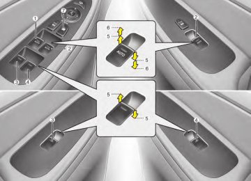
G220100BBH Headlight, position light, turn sig- nal light, side marker light and front fog light bulb replacement (1) Headlight (High) (2) Headlight (Low) (3) Front side marker light (4) Front turn signal light (5) Position light (6) Front fog light (if equipped)
(Continued) (cid:129) If a bulb becomes damaged or cracked, replace it immediately and carefully dispose of it.
(cid:129) Wear eye protection when chang- ing a bulb. Allow the bulb to cool down before handling it.
OHD076046
Headlight (HID type) bulb replace- ment (if equipped) If the light bulb is not operating, have the vehicle checked by an authorized HYUNDAI dealer.
G220101AUN-EU Headlight bulb
WARNING - HID Headlight low beam (if equipped)
Do not attempt to replace or inspect the low beam (XENON bulb) due to electric shock danger. If the low beam (XENON bulb) is not working, have your vehicle checked by an authorized HYUNDAI Dealer.
WARNING - Halogen bulbs (cid:129) Halogen bulbs contain pressur- ized gas that will produce small pieces of glass if broken.
(cid:129) Always handle the bulbs careful- ly, and avoid scratches and abra- sions. If the bulbs are lit, avoid contact with liquids.
(cid:129) Never touch the glass with bare hands. Residual oil may cause the bulb to overheat and burst when lit.
(Continued)
Maintenance
CAUTION
If your vehicle is equipped with High Intensity Discharge (HID) headlights, these headlights con- tain mercury.So if you need to have your vehicle disposed, you should remove the HID Headlights before disposal. The removed HID head- lights should be recycled, re-used or disposed as hazardous waste.
✽✽ NOTICE HID lamps have superior performance vs. halogen bulbs. HID lamps are esti- mated by the manufacturer to last twice as long or longer than halogen bulbs depending on their frequency of use. They will probably require replacement at some point in the life of the vehicle. Cycling the headlamps on and off more than typical use will shorten HID lamp life. HID lamps do not fail in the same manner as halogen incandescent lamps. If a headlamp goes out after a period of operation but will immediately relight when the headlamp switch is cycled it is likely the HID lamp needs to be replaced. HID lighting components are more com- plex than conventional halogen bulb and thus have higher replacement cost.
7 61
Maintenance
G220102ABH-EU Headlight (bulb type),front turn sig- nal,position,side marker and fog light bulbs (if equipped) If the light bulb is not operating, have the vehicle checked by an authorized HYUNDAI dealer.
62
OBH078031
OBH071032
G220200AEN Side repeater light bulb replace- ment (if equipped) If the light bulb is not operating, have the vehicle checked by an authorized HYUNDAI dealer.
G220300ABH Rear combination light bulb replacement (1) Back-up light (2) Rear turn signal light (3) Stop and tail light (4) Rear side marker light (5) Tail light
3. Remove the socket from the assembly by turning the socket counterclockwise until the tabs on the socket align with the slots on the assembly.
4. Remove the bulb from the socket by pressing it in and rotating it counter- clockwise until the tabs on the bulb align with the slots in the socket. Pull the bulb out of the socket.
5. Insert a new bulb by inserting it into the socket and rotating it until it locks into place.
6. Install the socket in the assembly by aligning the tabs on the socket with the slots in the assembly. Push the socket into the assembly and turn the socket clockwise.
7. Install the service cover by putting it
into the service hole.
Back-up,stop and tail light If the light is not operating, have the vehi- cle checked by an authorized HYUNDAI dealer.
OBH078033
OBH078034
Rear turn signal light 1. Open the trunk lid. 2. Remove the service cover by pulling out
the service cover.
Maintenance
OBH078035
OBH072101N
High mounted stop light 1.Remove the rear seat 1.Disconnect the negative battery cable. 2.Remove the rear seat cushion.
7 63
Maintenance
3.Loosen
the mounting bolts,
remove the rear seat back.
OBH072102N then
4.Disconnect the connector.
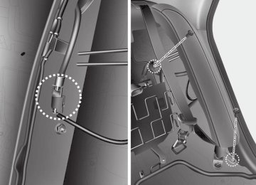
OVI071123N
OVI071124N 5.Push the hook, disconnect the main
connector.
Tightening torque : 34.3~53.9 N.m 3.5~5.5 kgf.m, 25.3~39.8 lb-ft
64
Maintenance
OVI071125N 6.Loosen the mounting bolts, then dis-
connect the connector. 7.Remove the side seat.
OBH072103N 2.Remove the rear package tray trim 1.Remove the rear door scuff trim.
OVI071132N 2.Loosen the mounting screw, then
remove the rear wheel house trim.
7 65
Maintenance
OBH072104N 3.Remove the cap, then loosen the
mounting screw.
4.Remove the rear pillar trim.
OVI071134N 5.Push the hook, remove the rear seat
belt cover.
OVI071135N 6.Remove the rear seat belt lower
anchor.
Tightening torque : 39.2~53.9 N.m 4.0~5.5 kgf.m 28.9~39.8 lb-ft
66
Maintenance
OVI071136N 7.Loosen the mounting screws, then
remove the package tray trim.
OVI071137N
OBH078036
3.Replace the high mounted stop
light
1.Remove the high mounted stop lamp
after removing screws.
2.Install a new light.
G220500AEN License plate light bulb replace- ment 1. Loosen the lens retaining screws with
a philips head screwdriver.
4.Installation Installation is the reverse of removal.
2. Remove the lens. 3. Remove the bulb by pulling it straight
out.
4. Install a new bulb. 5. Reinstall the lens securely with the
lens retaining screws.
7 67
Maintenance
Luggage lamp (if equipped)
Sunvisor lamp
OBH048086
OBH078046
G220900ABH Door courtesy lamp bulb replace- ment If the light is not operating, have the vehi- cle checked by an authorized HYUNDAI dealer.
Glove box lamp
OEN076044
68
OBH078037
G220600BBH Interior light bulb replacement 1. Using a flat-blade screwdriver, gently pry the lens from the interior light housing.
2. Remove the bulb by pulling it straight
out.
WARNING
Prior to working on the Interior Lights, ensure that the “OFF” but- ton is depressed to avoid burning your fingers or receiving an electric shock.
3. Install a new bulb in the socket. 4. Align the lens tabs with the interior light housing notches and snap the lens into place.
5. If the map lamp and room lamp are not operating, have the vehicle checked by an authorized HYUNDAI dealer.
CAUTION
Use care not to dirty or damage lens,lens tab,and plastic housings.
APPEARANCE CARE Exterior care G230101AUN Exterior general caution It is very important to follow the label directions when using any chemical cleaner or polish. Read all warning and caution statements that appear on the label.
Maintenance
G230102ABH Finish maintenance Washing To help protect your vehicle’s finish from rust and deterioration, wash it thoroughly and frequently at least once a month with lukewarm or cold water. If you use your vehicle for off-road driv- ing, you should wash it after each off- road trip. Pay special attention to the removal of any accumulation of salt, dirt, mud, and other foreign materials. Make sure the drain holes in the lower edges of