- 2003 Honda Civic Coupe Owners Manuals
- Honda Civic Coupe Owners Manuals
- 1994 Honda Civic Coupe Owners Manuals
- Honda Civic Coupe Owners Manuals
- 2005 Honda Civic Coupe Owners Manuals
- Honda Civic Coupe Owners Manuals
- 2008 Honda Civic Coupe Owners Manuals
- Honda Civic Coupe Owners Manuals
- 1996 Honda Civic Coupe Owners Manuals
- Honda Civic Coupe Owners Manuals
- 2007 Honda Civic Coupe Owners Manuals
- Honda Civic Coupe Owners Manuals
- 2011 Honda Civic Coupe Owners Manuals
- Honda Civic Coupe Owners Manuals
- 1993 Honda Civic Coupe Owners Manuals
- Honda Civic Coupe Owners Manuals
- 2001 Honda Civic Coupe Owners Manuals
- Honda Civic Coupe Owners Manuals
- 2012 Honda Civic Coupe Owners Manuals
- Honda Civic Coupe Owners Manuals
- 1998 Honda Civic Coupe Owners Manuals
- Honda Civic Coupe Owners Manuals
- 1995 Honda Civic Coupe Owners Manuals
- Honda Civic Coupe Owners Manuals
- 1999 Honda Civic Coupe Owners Manuals
- Honda Civic Coupe Owners Manuals
- 2010 Honda Civic Coupe Owners Manuals
- Honda Civic Coupe Owners Manuals
- 1997 Honda Civic Coupe Owners Manuals
- Honda Civic Coupe Owners Manuals
- 2006 Honda Civic Coupe Owners Manuals
- Honda Civic Coupe Owners Manuals
- 2004 Honda Civic Coupe Owners Manuals
- Honda Civic Coupe Owners Manuals
- 2009 Honda Civic Coupe Owners Manuals
- Honda Civic Coupe Owners Manuals
- 2002 Honda Civic Coupe Owners Manuals
- Honda Civic Coupe Owners Manuals
- 2000 Honda Civic Coupe Owners Manuals
- Honda Civic Coupe Owners Manuals
- Download PDF Manual
-
come on when the engine is running. If it starts flashing or stays on, the oil pressure has dropped very low or lost pressure. Serious engine damage is possible, and you should take immediate action.
Running the engine with low oil pressure can cause serious mechanical damage almost immediately. Turn of f the engine as soon as you can saf ely get the vehicle stopped.
1.
2.
3.
4.
Safely pull off the road, and shut off the engine. Turn on the hazard warning indicators.
Let the vehicle sit for a minute. Open the hood, and check the oil level (see page ). An engine very low on oil can lose pressure during cornering and other driving maneuvers.
183
If necessary, add oil to bring the level back to the full mark on the dipstick (see page
220
).
Start the engine, and watch the oil pressure indicator. If it does not go out within 10 seconds, turn off the engine. There is a mechanical problem that needs to be repaired before you can continue driving (see 272
Emergency Towing ).
on page
Charging System Indicator
If the charging system indicator comes on brightly
when the engine is running, the battery is not being charged.
Immediately turn off all electrical accessories. Try not to use other electrically operated controls such as the power windows. Keep the engine running; starting the engine will discharge the battery rapidly.
Go to a service station or garage where you can get technical assistance.
263
Main MenuTable of Contentsst 05/08/02 15:15:18 31SVA600 0267
Malfunction Indicator Lamp
If the indicator comes on while driving, it means one
of the engine’s emissions control systems may have a problem. Even though you may feel no difference in your vehicle’s performance, it can reduce your fuel economy and cause increased emissions. Continued operation may cause serious damage.
If you have recently refueled your vehicle, the indicator coming on could be due to a loose or missing fuel fill cap. You will also see a ‘‘CHECK FUEL CAP’’ message on the information display. Tighten the cap until it clicks at least once (see page ). Tightening the cap will not turn the indicator off immediately; it can take several days of normal driving.
181
264
If the indicator comes on repeatedly, even though it may turn off as you continue driving, have the vehicle checked by your dealer as soon as possible.
If your vehicle battery has been disconnected or gone dead, these codes are erased. It can take several days of driving under various conditions to set the codes again.
To check if they are set, turn the ignition switch to the ON (II) position, without starting the engine. The malfunction indicator lamp will come on for 20 seconds. If it then goes off, the readiness codes are set. If it blinks five times, the readiness codes are not set. If possible, do not take your vehicle for a state emissions test until the readiness codes are set. Refer to Emissions Testing information (see page
State for more ).
286
If you keep driving with the malf unction indicator lamp on, you can damage your vehicle’s emissions controls and engine. Those repairs may not be covered by your vehicle’s warranties.
This indicator may also come on with the ‘‘D’’ indicator.
Readiness Codes Your vehicle has certain ‘‘readiness codes’’ that are part of the on-board diagnostics for the emissions systems. In some states, part of the emissions testing is to make sure these codes are set. If they are not set, the test cannot be completed.
Main MenuTable of Contentsst 05/08/02 15:15:26 31SVA600 0268
U.S.
Canada
The brake system indicator normally comes on when you turn the ignition switch to the ON (II) position and as a reminder to check the parking brake. It will stay on if you do not fully release the parking brake.
If the brake system indicator comes on while driving, the brake fluid level is probably low. Press lightly on the brake pedal to see if it feels normal. If it does, check the brake fluid level thenexttimeyoustopataservice station (see page
230
).
If the fluid level is low, take your vehicle to a dealer, and have the brake system inspected for leaks or worn brake pads.
Brake System Indicator
If the ABS indicator comes on with the brake system indicator, have your vehicle inspected by your dealer immediately.
However, if the brake pedal does not feel normal, you should take immediate action. A problem in one part of the system’s dual circuit design will still give you braking at two wheels. You will feel the brake pedal go down much farther before the vehicle begins to slow down, and you will have to press harder on the pedal.
Slow down by shifting to a lower gear, and pull to the side of the road when it is safe. Because of the long distance needed to stop, it is hazardous to drive the vehicle. You should have it towed and repaired as soon as possible (see Towing 272
Emergency ).
on page
If you must drive the vehicle a short distance in this condition, drive slowly and carefully.
265
Main MenuTable of Contentsst 05/08/02 15:15:36 31SVA600 0269
Fuses
INTERIOR
UNDER-HOOD
TAB
The vehicle’s fuses are contained in two fuse boxes.
The interior fuse box is on the driver’s lower left side.
The under-hood fuse box is in the engine compartment on the driver’s side, next to the brake fluid reservoir. To open it, push the tabs as shown.
266
270
and
Checking and Replacing Fuses If something electrical in your vehicle stops working, check for a blown fuse first. Determine from the chart on pages , or the diagram on the fuse box lid, which fuse or fuses control that device. Check those fuses first, but check all the fuses before deciding that a blown fuse is the cause. Replace any blown fuses, and check if the device works.
271
Main MenuTable of Contentsst 05/08/02 15:15:54 31SVA600 0271
If you cannot drive the vehicle without fixing the problem, and you do not have a spare fuse, take a fuse of the same rating or a lower rating from one of the other circuits. Make sure you can do without that circuit temporarily (such as the accessory power socket or radio).
If you replace the blown fuse with a spare fuse that has a lower rating, it might blow out again. This does not indicate anything wrong. Replace the fuse with one of the correct rating as soon as you can.
Replacing a f use with one that has a higher rating greatly increases the chances of damaging the electrical system. If you do not have a replacement f use with the proper rating f or the circuit, install one with a lower rating.
6.
If the replacement fuse of the same rating blows in a short time, there is probably a serious electrical problem in your vehicle. Leave the blown fuse in that circuit and have your vehicle checked by a qualified mechanic.
Fuses
BLOWN
5.
Look for a blown wire inside the fuse. If it is blown, replace it with one of the spare fuses of the same rating or lower.
268
Main MenuTable of Contentsst 05/08/02 15:16:01 31SVA600 0272
SPARE FUSES
FUSE PULLER
3.
Your vehicle has spare fuses on the back of the under-hood fuse box cover.
AllmodelsexceptDX If the driver’s power window fuse is removed, the AUTO function of the driver’s window will be disabled. You should reset the AUTO feature, (see page
97
).
If the radio fuse is removed, the audio system will disable itself. The nexttimeyouturnontheradioyou will see ‘‘ENTER CODE’’ in the frequency display. Use the preset buttons to enter the digit code (see page
172
).
When the audio system is disabled, the clock setting in the audio system will be canceled. You will need to reset the clock (see page
173
).
Fuses
269
Main MenuTable of Contentsst 05/08/02 15:16:10 31SVA600 0273
Fuse Locations
UNDER-HOOD FUSE BOX
No.
Amps.
Circuits Protected
100 A 70 A 80 A 50 A 30 A 30 A 50 A 40 A −
270
*
Main Fuse EPS Option Ignition Switch Main ABS Motor ABS F/S Headlight Main Power Window Main Not Used
No.
Amps.
Circuits Protected
Fan Moter Main Fan Moter (A/T) Main Fan Moter (M/T) Rear Defroster Blower Hazard FI Stop, Horn Not Used Not Used Oil Level Sensor Not Used Not Used Ignition Coil FI Main MG Clutch DBW Interior Light Back Up
10
11
12
13
14
15
16
17
18
19
20
21
22
2320 A 30 A 20 A 40 A 40 A 10 A 15 A 15 A − − 7.5 A − − 15 A 15 A 7.5 A 15 A 7.5 A 10 A
*
: Si model
Main MenuTable of Contentsst 05/08/02 15:16:22 31SVA600 0274
INTERIOR FUSE BOX
Fuse Locations
No.
Amps.
Circuits Protected
No. Amps.
Circuits Protected
No. Amps.
Circuits Protected
7.5 A 15 A 10 A 7.5 A 15 A 20 A − −
Power Window Fuel Pump IG1 ACG ABS Audio Amp Front Fog Lights Not Used Not Used
*
*
10
11
12
13
14
15
167.5 A
7.5 A 10 A 10 A 10 A 7.5 A 7.5 A 10 A
ODS (Occupant Detection System) Meter SRS Right Headlight High Beam Left Headlight High Beam Small Lights (Interior) Small Lights (Exterior) Right Headlight Low Beam
17
18
19
20
21
22
23
24
25
26
27
28
29
3010 A 20 A 15 A − 20 A − − 20 A 20 A 20 A 20 A 15 A 15 A 20 A
− − − − 7.5 A 10 A 7.5 A 30 A
31
32
33
34
35
36
37
38
: If equipped*
*
Left Headlight Low Beam Headlight High Beam Main Small Lights Main Not Used Headlight Low Beam Main Not Used Not Used Moonroof Door Lock Driver’s Power Window HAC Option Rear Accessory Socket Accessory Front Passenger’s Power Window Not Used Not Used Not Used Not Used Accessory, Radio IG2 HAC Daytime Running Lights Front Wiper
*
271
Main MenuTable of Contentsst 05/08/02 15:16:39 31SVA600 0275
Emergency Towing
If your vehicle needs to be towed, call a professional towing service or organization. Never tow your vehicle with just a rope or chain. It is very dangerous.
There are two ways to tow your vehicle:
−
Flat-bedEquipment loads your vehicle on the back of a truck. port your vehicle.
This is the best way to trans-
The operator
−
The tow
Wheel-liftEquipment truck uses two pivoting arms that go under the front tires and lift them off the ground. The rear tires remain on the ground. way to tow your vehicle.
This is an acceptable
272
If, due to damage, your vehicle must be towed with the front wheels on the ground, do this:
ManualTransmission:
Release the parking brake. Shift the transmission to neutral. Leave the ignition switch in the ACCESSORY (I) position so the steering wheel does not lock.
AutomaticTransmission:
Release the parking brake. Start the engine. Shift to D, then to N. Turn off the engine. Leave the ignition switch in the ACCESSORY (I) position so the steering wheel does not lock.
Improper towing preparation will damage the transmission. Follow the above procedure exactly. If you cannot shif t the transmission or start the engine (automatic transmission), your vehicle must be transported with the f ront wheels of f the ground.
With the front wheels on the ground, do not tow the vehicle more than 50
miles (80 km), and keep the speed below 35 mph (55 km/h).Do not tie down the vehicle at an angle that would allow the towing cables to contact the vehicle’s front bumper. To avoid possible damage, protect the front bumper with tape.
If your vehicle is equipped with a front spoiler, remove it before towing so it is not damaged.
Main MenuTable of Contentsst 05/08/02 15:16:44 31SVA600 0276
Emergency Towing
Trying to lif t or tow your vehicle by the bumpers will cause serious damage. The bumpers are not designed to support the vehicle’s weight.
The steering system can be damaged if the steering wheel is locked. Leave the ignition switch in the ACCESSORY (I) position, and make sure the steering wheel turns f reely bef ore you begin towing.
273
Main MenuTable of Contentsst 05/08/02 15:16:51 31SVA600 0278
Technical Information
The diagrams in this section give you the dimensions and capacities of your vehicle, and the locations of the identification numbers. It also includes information you should know about your vehicle’s tires and emissions control systems.
Identification Numbers Specifications DOT Tire Quality Grading
................ ................................
. 276
. 278(U.S. Vehicles)
......................
. 280
Uniform Tire Quality
Grading Treadwear Traction Temperature
.................................. ................................. ...................................... ............................. .................................
Tire Labeling
. 280
. 280
. 280
. 281
. 282Emissions Controls ....................... The Clean Air Act ..................... Crankcase Emissions Control .................................... Evaporative Emissions Control ....................................
System
System
Onboard Refueling Vapor
. 283
. 283. 283
. 283
Recovery
. 283
Exhaust Emissions Controls . 284
. 284................................ ... ....................
PGM-FI System Ignition Timing Control
System
................................ Exhaust Gas Recirculation ....................
(EGR)System
Three Way Catalytic
. 284
. 284
Converter
Replacement Parts
. 284
........................... .................... . 284
Three Way Catalytic Converter . 285
.. .............. State Emissions Testing . 286275
Main Menust 05/08/02 15:16:58 31SVA600 0279
Identification Numbers
Your vehicle has several identifying numbers located in various places.
The vehicle identification number (VIN) is the 17-digit number your dealer uses to register your vehicle for warranty purposes. It is also necessary for licensing and insuring your vehicle. The easiest place to find the VIN is on a plate fastened to the top of the dashboard. You can see it by looking through the windshield on the driver’s side. It is also on the certification label attached to the driver’s doorjamb, and is stamped on the engine compartment bulkhead. The VIN is also provided in bar code on the certification label.
To access the VIN in the engine compartment, slide the lid on the back of the engine compartment. Make sure to close the lid before closing the hood.
276
LID
VEHICLE IDENTIFICATION NUMBER
CERTIFICATION LABEL
Main MenuTable of Contentsst 05/08/02 15:17:04 31SVA600 0280
The engine number is stamped into the engine block. It is on the front.
The transmission number is on a label on top of the transmission.
DX, Canadian DX-G, LX, and EX
Si
Identification Numbers
ENGINE NUMBER
AUTOMATIC/MANUAL TRANSMISSION NUMBER
ENGINE NUMBER
MANUAL TRANSMISSION NUMBER
277
Main MenuTable of Contentsst 05/08/02 15:17:28 31SVA600 0281
Specifications
Dimensions Length Width Height Wheelbase Track
Front Rear
Weights Gross vehicle weight rating
Engine Type
Bore x Stroke
Displacement
Compression ratio
Spark plugs *
Spark plugs *
* *
1 : 2 :
DX, Canadian DX-G, LX, EX Si
278
174.8 in (4,440 mm) 68.9 in (1,751 mm) 55.0 in (1,396 mm) 104.3 in (2,650 mm) 59.0 in (1,499 mm) 60.1 in (1,526 mm)
See the certification label attached to the driver’s doorjamb.
Water cooled 4-stroke
SOHC VTEC , DOHC i-VTEC * 4-cylinder gasoline engine
*
3.19 x 3.44 in (81.0 x 87.3 mm)
3.39 x 3.39 in (86 x 86 mm)
110 cu-in (1,799 cm ) 122 cu-in (1,998 cm )
*
*
*
*
10.5
11.0
IZFR6K-11S SKJ20DR-M11S IFR7G-11KS SK22PR-M11SNGK: DENSO: NGK: DENSO:
Capacities Fuel tank
Engine coolant
Change *
Total
A/T M/T
A/T M/T
13.2 US gal (50 )
Approx. 1.45 US gal (5.5 ) * 1.37 US gal (5.2 ) * 1.19 US gal (4.5 ) * 1.88 US gal (7.1 ) * 1.72 US gal (6.5 ) * 1.80 US gal (6.8 ) *
Engine oil
Change *
Including filter Without filter
Total
Change
Total
Change Total
U.S. Vehicles Canada Vehicles
Manual trans- mission fluid
Automatic transmission fluid Windshield washer reservoir 1 : *
3.9 US qt (3.7 ) * 4.6 US qt (4.4 ) * 3.7 US qt (3.5 ) * 4.4 US qt (4.2 ) * 4.8 US qt (4.5 ) * 5.8 US qt (5.5 ) * 1.5 US qt (1.4 ) * 1.6 US qt (1.5 ) * * 1.7 US qt (1.6 ) * 1.8 US qt (1.7 ) 2.5 US qt (2.4 ) 6.2 US qt (5.9 )
2.6 US qt (2.5 ) 4.8 US qt (4.5 )
Including the coolant in the reserve tank and that remaining in the engine Reserve tank capacity: 0.11 US gal (0.4 ) Excluding the oil remaining in the engine U.S.: DX, LX, EX Si
Canada: DX, DX-G, LX, EX
* * *
2 : 3 : 4 :
Main MenuTable of Contentsst 05/08/02 15:17:54 31SVA600 0282
HFC-134a (R-134a) −
14.1 15.9 oz (400 450 g)
−
Fuses Interior
SP-10
Under-hood
Air Conditioning Refrigerant type Charge quantity Lubricant oil type
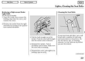
Lights Headlights (HI) Headlights (LO) Front turn signal/Side marker/ Parking light Rear turn signal lights Stop/Taillights Rear side marker lights Back-up lights High-mount brake light * License plate lights Ceiling light Spotlights Trunk light
*
: All models except for EX and Si
Battery Capacity
* * *
1 : U.S.: DX, LX, EX 2 : Canada: DX, DX-G,LX, EX 3 : Si
12 V 12 V 12 V
12 V 12 V 12 V 12 V 12 V 12 V 12 V 12 V 12 V
− − −
− − − − − − − − −
12 V 12 V 12 V 12 V
− − − −
(HB3) (HB4)
60 W 51 W 28/8 W
21 W 21/5 W 3 CP 18 W 21 W 3CP 8 W 8 W 5 W
*
36 AH/5 HR 38 AH/5 HR * 45 AH/20 HR 47 AH/20 HR
*
*
Specifications
See page 271 or the fuse label attached to the dashboard. See page 270 or the fuse box cover.
0.00 in (0.0 mm) 0.08 in (2.0 mm)
−
0° 1°30’ 7°
*
*
*
P195/65R15 89H P205/55R16 89H P215/45R17 87V 215/45R17 91W * T125/70D15 95M T125/70D16 96M
*
*
30 psi (210 kPa , 2.1 kgf/cm ) * 32 psi (220 kPa , 2.2 kgf/cm ) 32 psi (220 kPa , 2.2 kgf/cm ) 29 psi (200 kPa , 2.0 kgf/cm ) 60 psi (420 kPa , 4.2 kgf/cm )
* *
2,
Alignment Toe-in
Camber
Caster
Tires Size
Front Rear Front Rear Front
Front/Rear
Spare
Pressure
Front/Rear
Front * Rear * Spare
* * * * * *
1 : 2 : 3 : 4 : 5 : 6 :
U.S. DX, Canada DX, DX-G LX,EX Si (all season tires) U.S.: DX, LX, EX, Canada: DX, DX-G, LX, EX Optional for Si (summer tires) Si
279
Main MenuTable of Contentsst 05/08/02 15:18:05 31SVA600 0283
DOT Tire Quality Grading (U.S. Vehicles)
Treadwear The treadwear grade is a compara- tive rating based on the wear rate of the tire when tested under controlled conditions on a specified government test course. For example, a tire graded 150 would wear one and one- half (1 1/2) times as well on the government course as a tire graded 100. The relative performance of tires depends upon the actual condi- tions of their use, however, and may depart significantly from the norm due to variations in driving habits, service practices, and differences in road characteristics and climate.
The tires on your vehicle meet all U.S. Federal Safety Requirements. All tires are also graded for treadwear, traction, and temperature performance according to Department of Transportation (DOT) standards. The following explains these gradings.
Uniform Tire Quality Grading Quality grades can be found where applicable on the tire sidewall between the tread shoulder and the maximum section width. For example:
Treadwear 200
Traction AA Temperature AAll passenger car tires must conform to Federal Safety Requirements in addition to these grades.
280
−
AA, A, B, C
Traction The traction grades, from highest to lowest, are AA, A, B, and C. Those grades represent the tire’s ability to stop on wet pavement as measured under controlled conditions on specified government test surfaces of asphalt and concrete. A tire marked C may have poor traction performance.
Warning: The traction grade assigned to this tire is based on straight-ahead braking traction tests, and does not include acceleration, cornering, hydroplaning, or peak traction characteristics.
Main MenuTable of Contentsst 05/08/02 15:18:11 31SVA600 0284
−
A, B, C
Temperature The temperature grades are A (the highest), B, and C, representing the tire’s resistance to the generation of heat, and its ability to dissipate heat when tested under controlled conditions on a specified indoor laboratory test wheel. Sustained high temperature can cause the material of the tire to degenerate and reduce tire life, and excessive temperature can lead to sudden tire failure. Grade C corresponds to a level of performance that all passenger car tires must meet under the Federal Motor Vehicle Safety Standard No. 109. Grades B and A represent higher levels of performance on the laboratory test wheel than the minimum required by law.
DOT Tire Quality Grading (U.S. Vehicles)
Warning: The temperature grade for this tire is established for a tire that is properly inflated and not overloaded. Excessive speed, underinflation, or excessive loading, either separately or in combination, can cause heat buildup and possible tire failure.
281
Main MenuTable of Contentsst 05/08/02 15:18:30 31SVA600 0285
Tire Labeling
The tires that came on your vehicle have a number of markings. Those you should be aware of are described below.
TireSize Whenever tires are replaced, they should be replaced with tires of the same size. Below is an example of tire size with an explanation of what each component means.
P205/55R16 89H
−
Vehicle type (P indicates passenger vehicle).
205
−
Tire width in millimeters.
55
−
Aspect ratio (the tire’s section height as a percentage of its width).
−
Tire construction code (R indicates radial).
282
16
−
Rim diameter in inches.
FW6X
−
Tire type code.
2202
−
Date of manufacture.
MaximumTirePressure Max Press pressure the tire can hold.
The maximum air
−
MaximumTireLoad Max Load tire can carry at maximum air pressure.
−
The maximum load the
89
−
Load index (a numerical code associated with the maximum load the tire can carry).
−
Speed symbol (an alphabetical code indicating the maximum speed rating).
TireIdentificationNumber The tire identification number (TIN) is a group of numbers and letters that look like this example: DOT B97R FW6X 2202
DOT
−
This indicates that the tire meets all requirements of the U.S. Department of Transportation.
B97R
−
Manufacturer’s identification mark.
Main MenuTable of Contentsst 05/08/02 15:18:41 31SVA600 0286
The burning of gasoline in your vehicle’s engine produces several by- products. Some of these are carbon monoxide (CO), oxides of nitrogen (NOx), and hydrocarbons (HC). Gasoline evaporating from the tank also produces hydrocarbons. Con- trolling the production of NOx, CO, and HC is important to the environ- ment. Under certain conditions of sunlight and climate, NOx and HC react to form photochemical ‘‘smog.’’ Carbon monoxide does not contri- bute to smog creation, but it is a poisonous gas.
*
The Clean Air Act The United States Clean Air Act sets standards for automobile emissions. It also requires that automobile manufacturers explain to owners how their emissions controls work and what to do to maintain them. This section summarizes how the emissions controls work.
*
In Canada, Honda vehicles comply
with the Canadian emission requirements, as specified in an agreement with Environment Canada, at the time they are manufactured.
Crankcase Emissions Control System Your vehicle has a positive crankcase ventilation system. This keeps gasses that build up in the engine’s crankcase from going into the atmosphere. The positive crankcase ventilation valve routes them from the crankcase back to the
Emissions Controls
intake manifold. They are then drawn into the engine and burned.
Evaporative Emissions Control System As gasoline evaporates in the fuel tank, an evaporative emissions control canister filled with charcoal adsorbs the vapor. It is stored in this canister while the engine is off. After the engine is started and warmed up, the vapor is drawn into the engine and burned during driving.
Onboard Refueling Vapor Recovery The onboard refueling vapor recovery (ORVR) system captures the fuel vapors during refueling. The vapors are adsorbed in a canister filled with activated carbon. While driving, the fuel vapors are drawn into the engine and burned off.
283
Main MenuTable of Contentsst 05/08/02 15:18:54 31SVA600 0287
Emissions Controls
Exhaust Emissions Controls The exhaust emissions controls include three or four systems: PGM- FI, ignition timing control, exhaust gas recirculation (DX, LX, and EX), and three way catalytic converter. These systems work together to control the engine’s combustion and minimize the amount of HC, CO, and NOx that comes out the tailpipe. The exhaust emissions control systems are separate from the crankcase and evaporative emissions control systems.
PGM-FISystem The PGM-FI system uses sequential multiport fuel injection. It has three subsystems: air intake, engine control, and fuel control. The powertrain control module (PCM) in automatic transmission vehicles or the engine control module (ECM) in manual transmission vehicles uses various sensors to determine how much air is going into the engine. It
284
then controls how much fuel to inject under all operating conditions.
IgnitionTimingControlSystem This system constantly adjusts the ignition timing, reducing the amount of HC, CO, and NOx produced.
ExhaustGasRecirculation(EGR) System OnDX,LX,andEXmodels The exhaust gas recirculation (EGR) system takes some of the exhaust gas and routes it back into the intake manifold. Adding exhaust gas to the air/fuel mixture reduces the amount of NOx produced when the fuel is burned.
Replacement Parts The emissions control systems are designed and certified to work to- gether in reducing emissions to levels that comply with the Clean Air Act. To make sure the emissions remain low, you should use only new Honda replacement parts or their equivalent for repairs. Using lower quality parts may increase the emissions from your vehicle.
The emissions control systems are covered by warranties separate from the rest of your vehicle. Read your warranty manual for more informa- tion.
ThreeWayCatalyticConverter The three way catalytic converter is in the exhaust system. Through chemical reactions, it converts HC, CO, and NOx in the engine’s exhaust to carbon dioxide (CO ), nitrogen (N ), and water vapor.
Main MenuTable of Contentsst 05/08/02 15:19:05 31SVA600 0288
DX, Canadian DX-G, LX, EX
Si model
THREE WAY CATALYTIC CONVERTER The three way catalytic converter contains precious metals that serve as catalysts, promoting chemical reactions to convert the exhaust gasses without affecting the metals. The catalytic converter is referred to as a three-way catalyst, since it acts on HC, CO, and NOx. A replacement unit must be an original Honda part or its equivalent.
The three way catalytic converter must operate at a high temperature
THREE WAY CATALYTIC CONVERTER for the chemical reactions to take place. It can set on fire any combustible materials that come near it. Park your vehicle away from high grass, dry leaves, or other flammables.
A defective three way catalytic converter contributes to air pollution, and can impair your engine’s per- formance. Follow these guidelines to protect your vehicle’s three way catalytic converter.
Three Way Catalytic Converter
Always use unleaded gasoline. Even a small amount of leaded gasoline can contaminate the catalyst metals, making the three way catalytic converter ineffective.
Keep the engine tuned-up.
Have your vehicle diagnosed and repaired if it is misfiring, back- firing, stalling, or otherwise not running properly.
285
Main MenuTable of Contentsst 05/08/02 15:19:17 31SVA600 0289
State Emissions Testing
Testing of Readiness Codes If you take your vehicle for a state emissions test shortly after the battery has been disconnected or gone dead, it may not pass the test. This is because of certain ‘‘readiness codes’’ that must be set in the on- board diagnostics for the emissions systems. These codes are erased when the battery is disconnected, and set again only after several days of driving under a variety of conditions.
If the testing facility determines that the readiness codes are not set, you will be requested to return at a later date to complete the test. If you must get the vehicle retested within the next two or three days, you can condition the vehicle for retesting by doing the following.
Make sure the gas tank is nearly, but not completely full (around 3/4).
286
Make sure the vehicle has been parked with the engine off for 6
hours or more.Make sure the ambient temperature is between 40° and 95°F.
Without touching the accelerator pedal, start the engine, and let it idle for 20 seconds.
Keep the vehicle in Park (automatic transmission) or neutral (manual transmission). Increase the engine speed to 2,000
rpm, and hold it there until the temperature gauge rises to at least 1/4 of the scale (about 3 minutes).Select a nearby lightly traveled major highway where you can maintain a speed of 50 to 60 mph (80 to 97 km/h) for at least 20
minutes. Drive on the highway in D (A/T) or 5th (M/T). Do not usethe cruise control. When traffic allows, drive for 90 seconds without moving the accelerator pedal. (Vehicle speed may vary slightly; this is okay.) If you cannot do this for a continuous 90
seconds because of traffic conditions, drive for at least 30
seconds, then repeat it two more times (for a total of 90 seconds).Then drive in city/suburban traffic for at least 10 minutes. When traffic conditions allow, let the vehicle coast for several seconds without using the accelerator pedal or the brake pedal.
Stop the vehicle, turn off the ignition switch, and leave it off for 30 minutes.
If the testing facility determines the readiness codes are still not set, see your dealer.
Main MenuTable of Contentsst 05/08/02 15:19:21 31SVA600 0290
Warranty and Customer Relations
Customer Service
Information
Warranty Coverages Reporting Safety Defects
................................ ....................
. 288
. 289(U.S. Vehicles)
Authorized Manuals
.......................... .....................
. 290
. 291287
Main Menust 05/08/02 15:19:31 31SVA600 0291
Customer Service Information
Canadian Owners: CUSTOMER RELATIONS RELATIONS AVEC LA CLIENTÈLE Honda Canada Inc. 715 Milner Avenue Toronto, ON M1B 2K8
Tel: 1-888-9-HONDA-9
Fax: Toll-free 1-877-939-0909
Toronto (416) 287-4776In Puerto Rico and the U.S. Virgin Islands: Bella International P.O. Box 190816
San Juan, PR 00919-0816Tel: (787) 620-7028
Honda dealership personnel are trained professionals. They should be able to answer all your questions. If you encounter a problem that your dealership does not solve to your satisfaction, please discuss it with the dealership’s management. The service manager or general manager can help. Almost all problems are solved in this way.
If you are dissatisfied with the decision made by the dealership’s management, contact your Honda Customer Service Office.
U.S. Owners: American Honda Motor Co., Inc. Automobile Customer Service Mail Stop 500-2N-7A 1919 Torrance Boulevard Torrance, California 90501-2746
Tel: (800) 999-1009
288
When you call or write, please give us this information:
Vehicle identification number (see page
276
Name and address of the dealer who services your vehicle
Date of purchase
Mileage on your vehicle
Your name, address, and telephone number
A detailed description of the problem
Name of the dealer who sold the vehicle to you
Main MenuTable of Contentsst 05/08/02 15:19:45 31SVA600 0292
U.S. Owners Your new vehicle is covered by these warranties:
−
NewVehicleLimitedWarranty covers your new vehicle, except for the battery, emissions control systems, and accessories against defects in materials and workmanship.
these two
EmissionsControlSystemsDefects WarrantyandEmissions PerformanceWarranty − warranties cover your vehicle’s emissions control systems. Time, mileage, and coverage are conditional. Please read your warranty booklet for exact information.
OriginalEquipmentBatteryLimited Warranty to 100 percent credit toward a replacement battery.
this warranty gives up
−
Warranty Coverages
a seat SeatBeltLimitedWarranty belt that fails to function properly is covered for the useful life of the vehicle.
−
ReplacementBatteryLimited provides prorated Warranty coverage for a replacement battery purchased from your dealer.
−
all exterior body panels are
RustPerforationLimitedWarranty − covered for rust-through from the inside for the specified time period with no mileage limit.
ReplacementMufflerLifetime provides LimitedWarranty coverage for as long as the pur- chaser of the muffler owns the vehicle.
−
AccessoryLimitedWarranty − Honda accessories are covered under this warranty. Time and mileage limits depend on the type of accessory and other factors. Please read your warranty booklet for details.
ReplacementPartsLimited covers all Honda Warranty replacement parts against defects in materials and workmanship.
−
Restrictions and exclusions apply to all these warranties. Please read the 2006 Honda warranty information booklet that came with your vehicle for precise information on warranty coverages. Your vehicle’s original tires are covered by their manufacturer. Tire warranty information is in a separate booklet.
Canadian Owners Please refer to the 2006 warranty manual that came with your vehicle.
289
Main MenuTable of Contentsst 05/08/02 15:19:50 31SVA600 0293
Reporting Safety Defects (U.S. Vehicles)
If you believe that your vehicle has a defect which could cause a crash or could cause injury or death, you should immediately inform the National Highway Traffic Safety Administration (NHTSA) in addition to notifying American Honda Motor Co., Inc.
If NHTSA receives similar com- plaints, it may open an investigation, and if it finds that a safety defect exists in a group of vehicles, it may order a recall and remedy campaign. However, NHTSA cannot become involved in individual problems between you, your dealer, or American Honda Motor Co., Inc.
To contact NHTSA, you may call the Vehicle Safety Hotline toll-free at 1- 888-327-4236 (TTY 1-800-424-9153); go to http://www.safercar.gov; or write to: Administrator, NHTSA, 400
Seventh Street, SW., Washington, DC 20590. You can also obtain other information about motor vehicle safety from http://www.safercar.gov.290
Main MenuTable of Contentsst 05/08/02 15:20:04 31SVA600 0294