- Download PDF Manual
-
clutch retainer and all their associated parts are also rotating, all being directly connected to the input shaft. The power flow from the engine through the front clutch hub and rear clutch retainer stops at the rear clutch retainer. Therefore, no power flow to the output shaft occurs because no clutches are applied. The only mechanism in use at this time is the park- ing sprag (Fig. 3), which locks the parking gear on the output shaft to the transmission case.
Fig.4NeutralPowerflow
1 - PAWL DISENGAGED FOR NEUTRAL 2 - PARK SPRAG 3 - OUTPUT SHAFT 4 - CAM 5 - PAWL
Fig.3ParkPowerflow
1 - PAWL ENGAGED FOR PARK 2 - PARK SPRAG 3 - OUTPUT SHAFT
DR AUTOMATIC TRANSMISSION - 46RE (Continued) REVERSE POWERFLOW
selector
is moved into
When the gear
the REVERSE position (Fig. 5), the front clutch and the rear band are applied. With the application of the front clutch, engine torque is applied to the sun gear, turning it in a clockwise direction. The clockwise rotation of the sun gear causes the rear planet pin- ions to rotate against engine rotation in a counter- clockwise direction. The rear band is holding the low reverse drum, which is splined to the rear carrier.
AUTOMATIC TRANSMISSION - 46RE
21 - 135
Since the rear carrier is being held, the torque from the planet pinions is transferred to the rear annulus gear, which is splined to the output shaft. The output shaft in turn rotates with the annulus gear in a counterclockwise direction giving a reverse gear out- put. The entire transmission of torque is applied to the rear planetary gearset only. Although there is torque input to the front gearset through the sun gear, no other member of the gearset is being held. During the entire reverse stage of operation, the front planetary gears are in an idling condition.
1 - FRONT CLUTCH ENGAGED 2 - OUTPUT SHAFT 3 - LOW/REVERSE BAND APPLIED 4 - INPUT SHAFT
Fig.5ReversePowerflow
5 - OUTPUT SHAFT 6 - INPUT SHAFT 7 - FRONT CLUTCH ENGAGED 8 - LOW/REVERSE BAND APPLIED
AUTOMATIC TRANSMISSION - 46RE
21 - 136
AUTOMATIC TRANSMISSION - 46RE (Continued) FIRST GEAR POWERFLOWWhen the gearshift lever is moved into the DRIVE position the transmission goes into first gear (Fig. 6). As soon as the transmission is shifted from PARK or NEUTRAL to DRIVE, the rear clutch applies, apply- ing the rear clutch pack to the front annulus gear. Engine torque is now applied to the front annulus gear turning it in a clockwise direction. With the front annulus gear turning in a clockwise direction, it causes the front planets to turn in a clockwise direc- tion. The rotation of the front planets cause the sun to revolve in a counterclockwise direction. The sun gear now transfers its counterclockwise rotation to the rear planets which rotate back in a clockwise
DR
direction. With the rear annulus gear stationary, the rear planet rotation on the annulus gear causes the rear planet carrier to revolve in a counterclockwise direction. The rear planet carrier is splined into the low-reverse drum, and the low reverse drum is splined to the inner race of the over-running clutch. With the over-running clutch locked, the planet car- rier is held, and the resulting torque provided by the planet pinions is transferred to the rear annulus gear. The rear annulus gear is splined to the output shaft and rotated along with it (clockwise) in an underdrive gear reduction mode.
1 - OUTPUT SHAFT 2 - OVER-RUNNING CLUTCH HOLDING 3 - REAR CLUTCH APPLIED 4 - OUTPUT SHAFT
5 - OVER-RUNNING CLUTCH HOLDING 6 - INPUT SHAFT 7 - REAR CLUTCH APPLIED 8 - INPUT SHAFT
Fig.6FirstGearPowerflow
AUTOMATIC TRANSMISSION - 46RE
21 - 137
DR AUTOMATIC TRANSMISSION - 46RE (Continued) SECOND GEAR POWERFLOW
In DRIVE-SECOND (Fig. 7), the same elements are applied as in MANUAL-SECOND. Therefore, the power flow will be the same, and both gears will be discussed as one in the same. In DRIVE-SECOND, the transmission has proceeded from first gear to its shift point, and is shifting from first gear to second. The second gear shift is obtained by keeping the rear clutch applied and applying the front (kickdown) band. The front band holds the front clutch retainer that is locked to the sun gear driving shell. With the rear clutch still applied, the input is still on the front annulus gear turning it clockwise at engine speed.
Now that the front band is holding the sun gear sta- tionary, the annulus rotation causes the front planets to rotate in a clockwise direction. The front carrier is then also made to rotate in a clockwise direction but at a reduced speed. This will transmit the torque to the output shaft, which is directly connected to the front planet carrier. The rear planetary annulus gear will also be turning because it is directly splined to the output shaft. All power flow has occurred in the front planetary gear set during the drive-second stage of operation, and now the over-running clutch, in the rear of the transmission, is disengaged and freewheeling on its hub.
1 - KICKDOWN BAND APPLIED 2 - OUTPUT SHAFT 3 - REAR CLUTCH ENGAGED 4 - OUTPUT SHAFT 5 - OVER-RUNNING CLUTCH FREE-WHEELING
Fig.7SecondGearPowerflow 6 - INPUT SHAFT 7 - REAR CLUTCH APPLIED 8 - KICKDOWN BAND APPLIED 9 - INPUT SHAFT
AUTOMATIC TRANSMISSION - 46RE
21 - 138
AUTOMATIC TRANSMISSION - 46RE (Continued) DIRECT DRIVE POWERFLOWtakes place,
The vehicle has accelerated and reached the shift point for the 2-3 upshift into direct drive (Fig. 8). When the shift the front band is released, and the front clutch is applied. The rear clutch stays applied as it has been in all the forward gears. With the front clutch now applied, engine torque is now on the front clutch retainer, which is locked to the sun gear driving shell. This means that the sun gear is now turning in engine rotation (clock- wise) and at engine speed. The rear clutch is still applied so engine torque is also still on the front annulus gear. If two members of the same planetary
DR
set are driven, direct drive results. Therefore, when two members are rotating at the same speed and in the same direction, it is the same as being locked up. The rear planetary set is also locked up, given the sun gear is still the input, and the rear annulus gear must turn with the output shaft. Both gears are turning in the same direction and at the same speed. The front and rear planet pinions do not turn at all in direct drive. The only rotation is the input from the engine to the connected parts, which are acting as one common unit, to the output shaft.
1 - FRONT CLUTCH APPLIED 2 - OVER-RUNNING CLUTCH FREE-WHEELING 3 - OUTPUT SHAFT 4 - REAR CLUTCH APPLIED 5 - OUTPUT SHAFT
Fig.8DirectDrivePowerflow 6 - INPUT SHAFT 7 - OVER-RUNNING CLUTCH FREE-WHEELING 8 - REAR CLUTCH APPLIED 9 - FRONT CLUTCH APPLIED 10 - INPUT SHAFT
DR AUTOMATIC TRANSMISSION - 46RE (Continued) FOURTH GEAR POWERFLOW
Fourth gear overdrive range is electronically con- trolled and hydraulically activated. Various sensor inputs are supplied to the powertrain control module to operate the overdrive solenoid on the valve body. The solenoid contains a check ball that opens and closes a vent port in the 3-4 shift valve feed passage. The overdrive solenoid (and check ball) are not ener- gized in first, second, third, or reverse gear. The vent port remains open, diverting line pressure from the 2-3 shift valve away from the 3-4 shift valve. The overdrive control switch must be in the ON position to transmit overdrive status to the PCM. A 3-4
upshift occurs only when the overdrive solenoid is energized by the PCM. The PCM energizes the over- drive solenoid during the 3-4 upshift. This causes the solenoid check ball to close the vent port allowing line pressure from the 2-3 shift valve to act directly on the 3-4 upshift valve. Line pressure on the 3-4
shift valve overcomes valve spring pressure moving the valve to the upshift position. This action exposes the feed passages to the 3-4 timing valve, 3-4 quick fill valve, 3-4 accumulator, and ultimately to the overdrive piston. Line pressure through the timing valve moves the overdrive piston into contact with the overdrive clutch. The direct clutch is disengaged before the overdrive clutch is engaged. The boost valve provides increased fluid apply pressure to the overdrive clutch during 3-4 upshifts, and when accel- erating in fourth gear. The 3-4 accumulator cushions overdrive clutch engagement to smooth 3-4 upshifts. The accumulator is charged at the same time as apply pressure acts against the overdrive piston.DIAGNOSIS AND TESTING
DIAGNOSIS AND TESTING - AUTOMATIC TRANSMISSION
Automatic transmission problems can be a result of poor engine performance, incorrect fluid level, incor- rect linkage or cable adjustment, band or hydraulic control pressure adjustments, hydraulic system mal- functions or electrical/mechanical component mal- functions. Begin diagnosis by checking the easily accessible items such as: fluid level and condition, linkage adjustments and electrical connections. A road test will determine if further diagnosis is neces- sary.
DIAGNOSIS AND TESTING - PRELIMINARY
Two basic procedures are required. One procedure for vehicles that are drivable and an alternate proce- dure for disabled vehicles (will not back up or move forward).
AUTOMATIC TRANSMISSION - 46RE
21 - 139
VEHICLE IS DRIVEABLE
(1) Check for transmission fault codes using DRBt
scan tool.
(2) Check fluid level and condition. (3) Adjust throttle and gearshift linkage if com- plaint was based on delayed, erratic, or harsh shifts. (4) Road test and note how transmission upshifts,
downshifts, and engages.
(5) Perform hydraulic pressure test if shift prob-
lems were noted during road test.
(6) Perform air-pressure test to check clutch-band
operation.
VEHICLE IS DISABLED
(1) Check fluid level and condition. (2) Check for broken or disconnected gearshift or
throttle linkage.
(3) Check for cracked, leaking cooler lines, or loose
or missing pressure-port plugs.
(4) Raise and support vehicle on safety stands, start engine, shift transmission into gear, and note following:
(a) If propeller shaft turns but wheels do not,
problem is with differential or axle shafts.
(b) If propeller shaft does not turn and transmis- sion is noisy, stop engine. Remove oil pan, and check for debris. If pan is clear, remove transmis- sion and check for damaged drive plate, converter, oil pump, or input shaft.
(c) If propeller shaft does not turn and transmis- sion is not noisy, perform hydraulic-pressure test to determine if problem is hydraulic or mechanical.
DIAGNOSIS AND TESTING - ROAD TESTING
Before road testing, be sure the fluid level and con- trol cable adjustments have been checked and adjusted if necessary. Verify that diagnostic trouble codes have been resolved.
Observe engine performance during the road test. A poorly tuned engine will not allow accurate analy- sis of transmission operation.
Operate the transmission in all gear ranges. Check for shift variations and engine flare which indicates slippage. Note if shifts are harsh, spongy, delayed, early, or if part throttle downshifts are sensitive.
Slippage indicated by engine flare, usually means clutch, band or overrunning clutch problems. If the condition is advanced, an overhaul will be necessary to restore normal operation.
A slipping clutch or band can often be determined by comparing which internal units are applied in the various gear ranges. The Clutch and Band Applica- tion chart provides a basis for analyzing road test results.
21 - 140
AUTOMATIC TRANSMISSION - 46RE (Continued)AUTOMATIC TRANSMISSION - 46RE
CLUTCH AND BAND APPLICATION CHART
DR
SHIFT LEVER
POSITION
Reverse Drive - First Drive - Second Drive - Third Drive - Fourth Manual Second Manual
First
TRANSMISSION CLUTCHES AND BANDS
OVERDRIVE CLUTCHES
FRONT CLUTCH
FRONT BAND
REAR
CLUTCH
REAR BAND
OVER-
RUNNING CLUTCH
OVER- DRIVE CLUTCH
DIRECT CLUTCH
OVER-
RUNNING CLUTCH
Note that the rear clutch is applied in all forward ranges (D, 2, 1). The transmission overrunning clutch is applied in first gear (D, 2 and 1 ranges) only. The rear band is applied in 1 and R range only.
Note that the overdrive clutch is applied only in fourth gear and the overdrive direct clutch and over- running clutch are applied in all ranges except fourth gear.
For example: If slippage occurs in first gear in D and 2 range but not in 1 range, the transmission overrunning clutch is faulty. Similarly, if slippage occurs in any two forward gears, the rear clutch is slipping.
Applying the same method of analysis, note that the front and rear clutches are applied simulta- neously only in D range third and fourth gear. If the transmission slips in third gear, either the front clutch or the rear clutch is slipping.
If the transmission slips in fourth gear but not in third gear, the overdrive clutch is slipping. By select- ing another gear which does not use these clutches, the slipping unit can be determined. For example, if the transmission also slips in Reverse, the front clutch is slipping. If the transmission does not slip in Reverse, the rear clutch is slipping.
If slippage occurs during the 3-4 shift or only in fourth gear, the overdrive clutch is slipping. Simi- larly, if the direct clutch were to fail, the transmis- sion would lose both reverse gear and overrun braking in 2 position (manual second gear).
If the transmission will not shift to fourth gear, the control switch, overdrive solenoid or related wiring may also be the problem cause.
This process of elimination can be used to identify a slipping unit and check operation. Proper use of the Clutch and Band Application Chart is the key.
Although road test analysis will help determine the slipping unit, the actual cause of a malfunction usu- ally cannot be determined until hydraulic and air pressure tests are performed. Practically any condi- tion can be caused by leaking hydraulic circuits or sticking valves.
Unless a malfunction is obvious, such as no drive in D range first gear, do not disassemble the trans- mission. Perform the hydraulic and air pressure tests to help determine the probable cause.
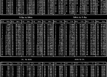
DIAGNOSIS AND TESTING - HYDRAULIC PRESSURE TEST
Hydraulic test pressures range from a low of one psi (6.895 kPa) governor pressure, to 300 psi (2068
kPa) at the rear servo pressure port in reverse.An accurate tachometer and pressure test gauges are required. Test Gauge C-3292 has a 100 psi range and is used at the accumulator, governor, and front servo ports. Test Gauge C-3293-SP has a 300 psi range and is used at the rear servo and overdrive ports where pressures exceed 100 psi.
DR AUTOMATIC TRANSMISSION - 46RE (Continued) Pressure Test Port Locations
Test ports are located at both sides of the transmis-
sion case (Fig. 9).
Line pressure is checked at the accumulator port on the right side of the case. The front servo pressure port is at the right side of the case just behind the filler tube opening.
The rear servo and governor pressure ports are at the right rear of the transmission case. The overdrive clutch pressure port is at the left rear of the case.
Fig.9PressureTestPortLocations
1 - REAR SERVO TEST PORT 2 - GOVERNOR TEST PORT 3 - ACCUMULATOR TEST PORT 4 - FRONT SERVO TEST PORT 5 - OVERDRIVE CLUTCH TEST PORT
Test One - Transmission In Manual Low
This test checks pump output, pressure regulation, and condition of the rear clutch and servo circuit. Both test gauges are required for this test.
(1) Connect tachometer to engine. Position tachom- eter so it can be observed from driver seat if helper will be operating engine. Raise vehicle on hoist that will allow rear wheels to rotate freely.
(2) Connect 100 psi Gauge C-3292 to accumulator port. Then connect 300 psi Gauge C-3293-SP to rear servo port.
AUTOMATIC TRANSMISSION - 46RE
21 - 141
(3) Disconnect throttle and gearshift cables from
levers on transmission valve body manual shaft.
(4) Have helper start and run engine at 1000 rpm. (5) Move transmission shift lever fully forward
into 1 range.
(6) Gradually move transmission throttle lever from full forward to full rearward position and note pressures on both gauges: † Line pressure at accumulator port should be 54-60 psi (372-414 kPa) with throttle lever forward and gradually increase to 90-96 psi (621-662 kPa) as throttle lever is moved rearward. † Rear servo pressure should be same as line pres-
sure within 3 psi (20.68 kPa).
Test Two - Transmission In 2 Range
This test checks pump output, line pressure and pressure regulation. Use 100 psi Test Gauge C-3292
for this test.(1) Leave vehicle in place on hoist and leave Test
Gauge C-3292 connected to accumulator port.
(2) Have helper start and run engine at 1000 rpm. (3) Move transmission shift lever one detent rear-
ward from full forward position. This is 2 range.
(4) Move transmission throttle lever from full for- ward to full rearward position and read pressure on gauge.
(5) Line pressure should be 54-60 psi
(372-414
kPa) with throttle lever forward and gradually increase to 90-96 psi (621-662 kPa) as lever is moved rearward.Test Three - Transmission In D Range Third Gear
This test checks pressure regulation and condition of the clutch circuits. Both test gauges are required for this test.
(1) Turn OD switch off. (2) Leave vehicle on hoist and leave Gauge C-3292
in place at accumulator port.
(3) Move Gauge C-3293-SP over to front servo port
for this test.
for this test.
(4) Have helper start and run engine at 1600 rpm
(5) Move transmission shift lever two detents rear-
ward from full forward position. This is D range.
(6) Read pressures on both gauges as transmission throttle lever is gradually moved from full forward to full rearward position: † Line pressure at accumulator in D range third gear, should be 54-60 psi (372-414 kPa) with throttle lever forward and increase as lever is moved rear- ward.† Front servo pressure in D range third gear, should be within 3 psi (21 kPa) of line pressure up to kickdown point.
21 - 142
AUTOMATIC TRANSMISSION - 46RE (Continued)AUTOMATIC TRANSMISSION - 46RE
DR
Test Four - Transmission In Reverse
Test Six - Transmission In Overdrive Fourth Gear
This test checks pump output, pressure regulation and the front clutch and rear servo circuits. Use 300
psi Test Gauge C-3293-SP for this test.(1) Leave vehicle on hoist and leave gauge C-3292
in place at accumulator port.
This test checks line pressure at the overdrive clutch in fourth gear range. Use 300 psi Test Gauge C-3293-SP for this test. The test should be performed on the road or on a chassis dyno.
(1) Remove tachometer; it is not needed for this
(2) Move 300 psi Gauge C-3293-SP back to rear
test.
servo port.
for test.
(3) Have helper start and run engine at 1600 rpm
(4) Move transmission shift
lever four detents rearward from full forward position. This is Reverse range.
(5) Move transmission throttle lever fully forward then fully rearward and note reading at Gauge C-3293-SP.
(6) Pressure should be 145 - 175 psi (1000-1207
kPa) with throttle lever forward and increase to 230 - 280 psi (1586-1931 kPa) as lever is gradually moved rearward.Test Five - Governor Pressure
This test checks governor operation by measuring governor pressure response to changes in vehicle speed. It is usually not necessary to check governor operation unless shift speeds are incorrect or if the transmission will not downshift. The test should be performed on the road or on a hoist that will allow the rear wheels to rotate freely.
(1) Move 100 psi Test Gauge C-3292 to governor
pressure port.
(2) Move transmission shift lever two detents rear-
ward from full forward position. This is D range.
(3) Have helper start and run engine at curb idle speed. Then firmly apply service brakes so wheels will not rotate.
(4) Note governor pressure: † Governor pressure should be no more than 20.6
kPa (3 psi) at curb idle speed and wheels not rotat- ing.† If pressure exceeds 20.6 kPa (3 psi), a fault exists in governor pressure control system. (5) Release brakes, slowly increase engine speed, and observe speedometer and pressure test gauge (do not exceed 30 mph on speedometer). Governor pres- sure should increase in proportion to vehicle speed. Or approximately 6.89 kPa (1 psi) for every 1 mph. (6) Governor pressure rise should be smooth and drop back to no more than 20.6 kPa (3 psi), after engine returns to curb idle and brakes are applied to prevent wheels from rotating.(7) Compare results of pressure test with analysis
chart.
(2) Move 300 psi Gauge to overdrive clutch pres- sure test port. Then remove other gauge and reinstall test port plug.
(3) Lower vehicle. (4) Turn OD switch on. (5) Secure test gauge so it can be viewed from
drivers seat.
(6) Start engine and shift into D range. (7) Increase vehicle speed gradually until 3-4 shift
occurs and note gauge pressure.
(8) Pressure should be 469-496 kPa (68-72 psi) with closed throttle and increase to 620-827 kPa (90- 120 psi) at 1/2 to 3/4 throttle. Note that pressure can increase to around 896 kPa (130 psi) at full throttle. (9) Return to shop or move vehicle off chassis
dyno.
PRESSURE TEST ANALYSIS CHART
TEST CONDITION
INDICATION
Line pressure OK during any one test Line pressure OK in R but low in D, 2, 1
Pressure low in D Fourth Gear Range Pressure OK in 1, 2 but low in D3 and R Pressure OK in 2 but low in R and 1
Front servo pressure in 2Pressure low in all positions
Governor pressure too high at idle speed
Governor pressure low at all mph figures
Lubrication pressure low at all throttle positions
Line pressure high
Line pressure low
Pump and regulator valve OK Leakage in rear clutch area (seal rings, clutch seals) Overdrive clutch piston seal, or check ball problem Leakage in front clutch area
Leakage in rear servo
Leakage in servo; broken servo ring or cracked servo piston Clogged filter, stuck regulator valve, worn or faulty pump, low oil level Governor pressure solenoid valve system fault. Refer to diagnostic book. Faulty governor pressure solenoid, transmission control module, or governor pressure sensor Clogged fluid cooler or lines, seal rings leaking, worn pump bushings, pump, clutch retainer, or clogged filter. Output shaft plugged, sticky regulator valve Sticky regulator valve, clogged filter, worn pump
DR AUTOMATIC TRANSMISSION - 46RE (Continued) DIAGNOSIS AND TESTING - AIR TESTING TRANSMISSION CLUTCH AND BAND OPERATION
Air-pressure testing can be used to check transmis- sion front/rear clutch and band operation. The test can be conducted with the transmission either in the vehicle or on the work bench, as a final check, after overhaul. Air-pressure testing requires that the oil pan and valve body be removed from the transmission. The servo and clutch apply passages are shown (Fig. 10).
Fig.10AirPressureTestPassages
1 - LINE PRESSURE TO ACCUMULATOR 2 - REAR SERVO APPLY 3 - FRONT SERVO APPLY 4 - FRONT SERVO RELEASE 5 - PUMP SUCTION 6 - PUMP PRESSURE 7 - FRONT CLUTCH APPLY 8 - REAR CLUTCH APPLY 9 - TO TORQUE CONVERTOR 10 - TO COOLER 11 - FROM TORQUE CONVERTER
Front Clutch Air Test
Place one or two fingers on the clutch housing and apply air pressure through front clutch apply pas- sage. Piston movement can be felt and a soft thump heard as the clutch applies.
Rear Clutch Air Test
Place one or two fingers on the clutch housing and apply air pressure through rear clutch apply passage. Piston movement can be felt and a soft thump heard as the clutch applies.
Front Servo Air Test
Apply air pressure to the front servo apply passage. The servo rod should extend and cause the band to
AUTOMATIC TRANSMISSION - 46RE
21 - 143
tighten around the drum. Spring pressure should release the servo when air pressure is removed.
Rear Servo Air Test
Apply air pressure to the rear servo apply passage. The servo rod should extend and cause the band to tighten around the drum. Spring pressure should release the servo when air pressure is removed.
DIAGNOSIS AND TESTING - CONVERTER HOUSING FLUID LEAK
When diagnosing converter housing fluid leaks,
two items must be established before repair.
(1) Verify that a leak condition actually exists. (2) Determined the true source of the leak. Some suspected converter housing fluid leaks may not be leaks at all. They may only be the result of residual fluid in the converter housing, or excess fluid spilled during factory fill or fill after repair. Converter housing leaks have several potential sources. Through careful observation, a leak source can be identified before removing the transmission for repair. Pump seal leaks tend to move along the drive hub and onto the rear of the converter. Pump body leaks follow the same path as a seal leak (Fig. 11). Pump vent or pump attaching bolt leaks are gen- erally deposited on the inside of the converter hous- ing and not on the converter itself (Fig. 11). Pump o-ring or gasket leaks usually travel down the inside of the converter housing. Front band lever pin plug leaks are generally deposited on the housing and not on the converter.
Fig.11ConverterHousingLeakPaths
1 - PUMP SEAL 2 - PUMP VENT 3 - PUMP BOLT 4 - PUMP GASKET 5 - CONVERTER HOUSING 6 - CONVERTER 7 - REAR MAIN SEAL LEAK
AUTOMATIC TRANSMISSION - 46RE
21 - 144
AUTOMATIC TRANSMISSION - 46RE (Continued) TORQUE CONVERTER LEAK POINTS Possible sources of converter leaks are: † Leaks at the weld joint around the outside diam- eter weld. † Leaks at the converter hub weld. CONVERTER HOUSING AREA LEAK CORRECTION(1) Remove converter. (2) Tighten front band adjusting screw until band is tight around front clutch retainer. This prevents front/rear clutches from coming out when oil pump is removed.
(3) Remove oil pump and remove pump seal. Inspect pump housing drainback and vent holes for obstructions. Clear holes with solvent and wire.
(4) Inspect pump bushing and converter hub. If bushing is scored, replace it. If converter hub is scored, either polish it with crocus cloth or replace converter.
(5) Install new pump seal, O-ring, and gasket. Replace oil pump if cracked, porous or damaged in any way. Be sure to loosen the front band before installing the oil pump, damage to the oil pump seal may occur if the band is still tightened to the front clutch retainer.
(6) Loosen kickdown lever pin access plug three turns. Apply Loctite™ 592, or Permatext No. 2 to
DR
plug threads and tighten plug to 17 N·m (150 in. lbs.) torque.
(7) Adjust front band. (8) Lubricate pump seal and converter hub with transmission fluid or petroleum jelly and install con- verter.
transmission and converter housing
(9) Install dust shield.
(10) Lower vehicle.
DIAGNOSIS AND TESTING - DIAGNOSIS CHARTS
The diagnosis charts provide additional reference when diagnosing a transmission fault. The charts provide general information on a variety of transmis- sion, overdrive unit and converter clutch fault condi- tions.
The hydraulic flow charts in the Schematics and Diagrams section of this group, outline fluid flow and hydraulic circuitry. Circuit operation is provided for PARK, NEUTRAL, FIRST, SECOND, THIRD, FOURTH, MANUAL FIRST, MANUAL SECOND, and REVERSE gear ranges. Normal working pres- sures are also supplied for each of the gear ranges.
DR AUTOMATIC TRANSMISSION - 46RE (Continued)
AUTOMATIC TRANSMISSION - 46RE
21 - 145
DIAGNOSIS CHARTS
CONDITION
POSSIBLE CAUSES
CORRECTION
HARSH ENGAGEMENT (FROM NEUTRAL TO DRIVE OR REVERSE)
1. Fluid Level Low. 2. Throttle Linkage Mis-adjusted. 3. Mount and Driveline Bolts Loose.
DELAYED ENGAGEMENT (FROM NEUTRAL TO DRIVE OR REVERSE)
4. U-Joint Worn/Broken.
5. Axle Backlash Incorrect.
6. Hydraulic Pressure Incorrect.
7. Band Mis-adjusted. 8. Valve Body Check Balls Missing.
9. Axle Pinion Flange Loose.
10. Clutch, band or planetary component damaged. 11. Converter Clutch Faulty. 1. Fluid Level Low. 2. Filter Clogged. 3. Gearshift Linkage Mis-adjusted.
4. Torque Converter Drain Back (Oil drains from torque converter into transmission sump).
5. Rear Band Mis-adjusted. 6. Valve Body Filter Plugged.
7. Oil Pump Gears Worn/Damaged.
8. Governor Circuit and Solenoid Valve Electrical Fault. 9. Hydraulic Pressure Incorrect.
10. Reaction Shaft Seal Rings Worn/Broken. 11. Rear Clutch/Input Shaft, Rear Clutch Seal Rings Damaged. 12. Regulator Valve Stuck. 13. Cooler Plugged.
1. Add Fluid 2. Adjust linkage - setting may be too long. 3. Check engine mount, transmission mount, propeller shaft, rear spring to body bolts, rear control arms, crossmember and axle bolt torque. Tighten loose bolts and replace missing bolts. 4. Remove propeller shaft and replace U-Joint. 5. Check per Service Manual. Correct as needed. 6. Check pressure. Remove, overhaul or adjust valve body as needed. 7. Adjust rear band. 8. Inspect valve body for proper check ball installation. 9. Replace nut and check pinion threads before installing new nut. Replace pinion gear if threads are damaged. 10. Remove, disassemble and repair transmission as necessary. 11. Replace converter. 1. Correct level and check for leaks. 2. Change filter. 3. Adjust linkage and repair linkage if worn or damaged. 4. If vehicle moves normally after 5
seconds after shifting into gear, no repair is necessary. If longer, inspect pump bushing for wear. Replace pump house. 5. Adjust band. 6. Replace fluid and filter. If oil pan and old fluid were full of clutch disc material and/or metal particles, overhaul will be necessary. 7. Remove transmission and replace oil pump. 8. Test with DRBT scan tool and repair as required. 9. Perform pressure test, remove transmission and repair as needed. 10. Remove transmission, remove oil pump and replace seal rings. 11. Remove and disassemble transmission and repair as necessary. 12. Clean. 13. Replace cooler.21 - 146
AUTOMATIC TRANSMISSION - 46RE (Continued)AUTOMATIC TRANSMISSION - 46RE
DR
CONDITION NO DRIVE RANGE (REVERSE OK)
NO DRIVE OR REVERSE (VEHICLE WILL NOT MOVE)
POSSIBLE CAUSES
CORRECTION
1. Fluid Level Low.
2. Gearshift Linkage/Cable Loose/Misadjusted. 3. Rear Clutch Burnt.
4. Valve Body Malfunction.
5. Transmission Overrunning Clutch Broken. 6. Input Shaft Seal Rings Worn/ Damaged.
7. Front Planetary Failed Broken. 1. Fluid Level Low.
2. Gearshift Linkage/Cable Loose/Misadjusted. 3. U-Joint/Axle/Transfer Case Broken.
4. Filter Plugged.
5. Oil Pump Damaged.
6. Valve Body Malfunctioned.
7. Transmission Internal Component Damaged.
8. Park Sprag not Releasing - Check Stall Speed, Worn/Damaged/Stuck. 9. Torque Converter Damage.
1. Add fluid and check for leaks if drive is restored. 2. Repair or replace linkage components.
3. Remove and disassemble transmission and rear clutch and seals. Repair/replace worn or damaged parts as needed. 4. Remove and disassemble valve body. Replace assembly if any valves or bores are damaged. 5. Remove and disassemble transmission. Replace overrunning clutch. 6. Remove and disassemble transmission. Replace seal rings and any other worn or damaged parts. 7. Remove and repair. 1. Add fluid and check for leaks if drive is restored. 2. Inspect, adjust and reassemble linkage as needed. Replace worn/damaged parts. 3. Perform preliminary inspection procedure for vehicle that will not move. Refer to procedure in diagnosis section. 4. Remove and disassemble transmission. Repair or replace failed components as needed. Replace filter. If filter and fluid contained clutch material or metal particles, an overhaul may be necessary. Replace cooler as necessary. 5. Perform pressure test to confirm low pressure. Replace pump body assembly if necessary. 6. Check and inspect valve body. Replace valve body (as assembly) if any valve or bore is damaged. Clean and reassemble correctly if all parts are in good condition. 7. Remove and disassemble transmission. Repair or replace failed components as needed. 8. Remove, disassemble, repair.
9. Inspect and replace as required.
DR AUTOMATIC TRANSMISSION - 46RE (Continued)
AUTOMATIC TRANSMISSION - 46RE
21 - 147
CONDITION
POSSIBLE CAUSES
CORRECTION
SHIFTS DELAYED OR ERRATIC (SHIFTS ALSO HARSH AT TIMES)
1. Fluid Level Low/High.
2. Fluid Filter Clogged.
3. Throttle Linkage Mis-adjusted.
4. Throttle Linkage Binding.
5. Gearshift Linkage/Cable Mis-adjusted. 6. Clutch or Servo Failure.
7. Governor Circuit Electrical Fault.
8. Front Band Mis-adjusted. 9. Pump Suction Passage Leak.
1. Gearshift Linkage/Cable Mis-adjusted/Damaged. 2. Park Sprag Sticking. 3. Rear Band Mis-adjusted/Worn. 4. Valve Body Malfunction.
5. Rear Servo Malfunction.
6. Direct Clutch in Overdrive Worn.
7. Front Clutch Burnt.
1. Governor Circuit Electrical Fault.
2. Valve Body Malfunction.
3. Front Servo/Kickdown Band Damaged/Burned. 1. Valve Body Malfunction.
NO REVERSE (D RANGES OK)
HAS FIRST/REVERSE ONLY (NO 1-2 OR 2-3
UPSHIFT)MOVES IN 2ND OR 3RD GEAR, ABRUPTLY DOWNSHIFTS TO LOW
1. Correct fluid level and check for leaks if low. 2. Replace filter. If filter and fluid contained clutch material or metal particles, an overhaul may be necessary. 3. Adjust linkage as described in service section. 4. Check cable for binding. Check for return to closed throttle at transmission. 5. Adjust linkage/cable as described in service section. 6. Remove valve body and air test clutch, and band servo operation. Disassemble and repair transmission as needed. 7. Test using DRBT scan tool and repair as required. 8. Adjust band. 9. Check for excessive foam on dipstick after normal driving. Check for loose pump bolts, defective gasket. Replace pump assembly if needed. 1. Repair or replace linkage parts as needed. 2. Replace overdrive annulus gear. 3. Adjust band; replace. 4. Remove and service valve body. Replace valve body if any valves or valve bores are worn or damaged. 5. Remove and disassemble transmission. Replace worn/damaged servo parts as necessary. 6. Disassemble overdrive. Replace worn or damaged parts. 7. Remove and disassemble transmission. Replace worn, damaged clutch parts as required. 1. Test using DRBT scan tool and repair as required. 2. Repair stuck 1-2 shift valve or governor plug. 3. Repair/replace.
1. Remove, clean and inspect. Look for stuck 1-2 valve or governor plug.
21 - 148
AUTOMATIC TRANSMISSION - 46RE (Continued)AUTOMATIC TRANSMISSION - 46RE
DR
CONDITION
POSSIBLE CAUSES
CORRECTION
NO LOW GEAR (MOVES IN 2ND OR 3RD GEAR ONLY)
1. Governor Circuit Electrical Fault.
2. Valve Body Malfunction.
NO KICKDOWN OR NORMAL DOWNSHIFT
3. Front Servo Piston Cocked in Bore. 4. Front Band Linkage Malfunction
1. Throttle Linkage Mis-adjusted. 2. Accelerator Pedal Travel Restricted. 3. Valve Body Hydraulic Pressures Too High or Too Low Due to Valve Body Malfunction or Incorrect Hydraulic Control Pressure Adjustments. 4. Governor Circuit Electrical Fault.
5. Valve Body Malfunction.
6. TPS Malfunction.
7. PCM Malfunction.
8. Valve Body Malfunction.
STUCK IN LOW GEAR (WILL NOT UPSHIFT)
1. Throttle Linkage Mis-adjusted/ Stuck.
2. Gearshift Linkage Mis-adjusted.
3. Governor Component Electrical Fault. 4. Front Band Out of Adjustment. 5. Clutch or Servo Malfunction.
1. Gearshift Linkage Mis-adjusted. 2. Rear Clutch Dragging/Warped. 3. Valve Body Malfunction.
CREEPS IN NEUTRAL
1. Test with DRBT scan tool and repair as required. 2. Remove, clean and inspect. Look for sticking 1-2 shift valve, 2-3 shift valve, governor plug or broken springs. 3. Inspect servo and repair as required.
4. Inspect linkage and look for bind in linkage. 1. Adjust linkage. 2. Verify floor mat is not under pedal, repair worn accelerator cable or bent brackets. 3. Perform hydraulic pressure tests to determine cause and repair as required. Correct valve body pressure adjustments as required.
4. Test with DRBT scan tool and repair as required. 5. Perform hydraulic pressure tests to determine cause and repair as required. Correct valve body pressure adjustments as required. 6. Replace sensor, check with DRBT scan tool. 7. Check with DRBT scan tool and replace if required. 8. Repair sticking 1-2, 2-3 shift valves, governor plugs, 3-4 solenoid, 3-4 shift valve, 3-4 timing valve. 1. Adjust linkage and repair linkage if worn or damaged. Check for binding cable or missing return spring. 2. Adjust linkage and repair linkage if worn or damaged. 3. Check operating pressures and test with DRBT scan tool, repair faulty component. 4. Adjust Band. 5. Air pressure check operation of clutches and bands. Repair faulty component. 1. Adjust linkage. 2. Disassemble and repair. 3. Perform hydraulic pressure test to determine cause and repair as required.
DR AUTOMATIC TRANSMISSION - 46RE (Continued)
AUTOMATIC TRANSMISSION - 46RE
21 - 149
CONDITION
BUZZING NOISE
SLIPS IN REVERSE ONLY
SLIPS IN FORWARD DRIVE RANGES
SLIPS IN LOW GEAR 9D9
ONLY, BUT NOT IN MANUAL 1 POSITIONPOSSIBLE CAUSES
1. Fluid Level Low 2. Shift Cable Mis-assembled.
3. Valve Body Mis-assembled.
4. Pump Passages Leaking.
5. Cooling System Cooler Plugged. 6. Overrunning Clutch Damaged. 1. Fluid Level Low. 2. Gearshift Linkage Mis-adjusted. 3. Rear Band Mis-adjusted. 4. Rear Band Worn. 5. Overdrive Direct Clutch Worn.
6. Hydraulic Pressure Too Low.
7. Rear Servo Leaking.
8. Band Linkage Binding. 1. Fluid Level Low. 2. Fluid Foaming.
3. Throttle Linkage Mis-adjusted. 4. Gearshift Linkage Mis-adjusted. 5. Rear Clutch Worn. 6. Low Hydraulic Pressure Due to Worn Pump, Incorrect Control Pressure Adjustments, Valve Body Warpage or Malfunction, Sticking, Leaking Seal Rings, Clutch Seals Leaking, Servo Leaks, Clogged Filter or Cooler Lines. 7. Rear Clutch Malfunction, Leaking Seals or Worn Plates. 8. Overrunning Clutch Worn, Not Holding (Slips in 1 Only). Overrunning Clutch Faulty.
CORRECTION
1. Add fluid and check for leaks. 2. Route cable away from engine and bell housing. 3. Remove, disassemble, inspect valve body. Reassemble correctly if necessary. Replace assembly if valves or springs are damaged. Check for loose bolts or screws. 4. Check pump for porous casting, scores on mating surfaces and excess rotor clearance. Repair as required. Loose pump bolts. 5. Replace cooler. 6. Replace clutch. 1. Add fluid and check for leaks. 2. Adjust linkage. 3. Adjust band. 4. Replace as required. 5. Disassemble overdrive. Repair as needed. 6. Perform hydraulic pressure tests to determine cause. 7. Air pressure check clutch-servo operation and repair as required. 8. Inspect and repair as required. 1. Add fluid and check for leaks. 2. Check for high oil level, bad pump gasket or seals, dirt between pump halves and loose pump bolts. Replace pump if necessary. 3. Adjust linkage. 4. Adjust linkage. 5. Inspect and replace as needed. 6. Perform hydraulic and air pressure tests to determine cause.
7. Air pressure check clutch-servo operation and repair as required. 8. Replace Clutch.
Replace overrunning clutch.
21 - 150
AUTOMATIC TRANSMISSION - 46RE (Continued)AUTOMATIC TRANSMISSION - 46RE
DR
CONDITION
POSSIBLE CAUSES
CORRECTION
GROWLING, GRATING OR SCRAPING NOISES
DRAGS OR LOCKS UP
1. Drive Plate Broken. 2. Torque Converter Bolts Hitting Dust Shield. 3. Planetary Gear Set Broken/ Seized. 4. Overrunning Clutch Worn/Broken.
5. Oil Pump Components Scored/ Binding. 6. Output Shaft Bearing or Bushing Damaged. 7. Clutch Operation Faulty.
8. Front and Rear Bands Mis- adjusted. 1. Fluid Level Low. 2. Clutch Dragging/Failed
3. Front or Rear Band Mis-adjusted. 4. Case Leaks Internally.
5. Servo Band or Linkage Malfunction. 6. Overrunning Clutch Worn.
7. Planetary Gears Broken.
8. Converter Clutch Dragging.
NO 4-3 DOWNSHIFT
1. Circuit Wiring and/or Connectors Shorted.
2. PCM Malfunction.
3. TPS Malfunction 4. Lockup Solenoid Not Venting.
5. Overdrive Solenoid Not Venting.
6. Valve Body Valve Sticking.
1. Replace. 2. Dust shield bent. Replace or repair.
3. Check for debris in oil pan and repair as required. 4. Inspect and check for debris in oil pan. Repair as required. 5. Remove, inspect and repair as required.
6. Remove, inspect and repair as required.
7. Perform air pressure check and repair as required. 8. Adjust bands.
1. Check and adjust level. 2. Air pressure check clutch operation and repair as required. 3. Adjust bands. 4. Check for leakage between passages in case. 5. Air pressure check servo operation and repair as required. 6. Remove and inspect clutch. Repair as required. 7. Remove, inspect and repair as required (look for debris in oil pan). 8. Check for plugged cooler. Inspect pump for excessive side clearance. Replace pump as required. 1. Test wiring and connectors with test lamp and volt/ohmmeter. Repair wiring as necessary. Replace connectors and/or harnesses as required. 2. Check PCM operation with DRBT scan tool. Replace PCM only if faulty. 3. Check TPS with DRBT scan tool at PCM. 4. Remove valve body and replace solenoid assembly if plugged or shorted. 5. Remove valve body and replace solenoid if plugged or shorted. 6. Repair stuck 3-4 shift valve or lockup timing valve.
DR AUTOMATIC TRANSMISSION - 46RE (Continued)
AUTOMATIC TRANSMISSION - 46RE
21 - 151
CONDITION NO 4-3 DOWNSHIFT WHEN CONTROL SWITCH IS TURNED OFF
POSSIBLE CAUSES
1. Control Switch Open/Shorted. 2. Overdrive Solenoid Connector Shorted. 3. PCM Malfunction.
4. Valve Body Stuck Valves.
CLUNK NOISE FROM DRIVELINE ON CLOSED THROTTLE 4-3
DOWNSHIFT3-4 UPSHIFT OCCURS IMMEDIATELY AFTER 2-3
SHIFT1. Transmission Fluid Low. 2. Throttle Cable Mis-adjusted. 3. Overdrive Clutch Select Spacer Wrong Spacer. 1. Overdrive Solenoid Connector or Wiring Shorted.
2. TPS Malfunction.
3. PCM Malfunction.
4. Overdrive Solenoid Malfunction. 5. Valve Body Malfunction.
WHINE/NOISE RELATED TO ENGINE SPEED
1. Fluid Level Low. 2. Shift Cable Incorrect Routing.
CORRECTION
1. Test and replace switch if faulty. 2. Test solenoids and replace if seized or shorted. 3. Test with DRBT scan tool. Replace PCM if faulty. 4. Repair stuck 3-4, lockup or lockup timing valve. 1. Add Fluid. 2. Adjust cable. 3. Replace overdrive piston thrust plate spacer. 1. Test connector and wiring for loose connections, shorts or ground and repair as needed. 2. Test TPS and replace as necessary. Check with DRBT scan tool. 3. Test PCM with DRBT scan tool and replace controller if faulty. 4. Replace solenoid. 5. Remove, disassemble, clean and inspect valve body components. Make sure all valves and plugs slide freely in bores. Polish valves with crocus cloth if needed. 1. Add fluid and check for leaks. 2. Check shift cable for correct routing. Should not touch engine or bell housing.
21 - 152
AUTOMATIC TRANSMISSION - 46RE (Continued)AUTOMATIC TRANSMISSION - 46RE
CONDITION
NO 3-4 UPSHIFT
POSSIBLE CAUSES
1. O/D Switch In OFF Position. 2. Overdrive Circuit Fuse Blown.
3. O/D Switch Wire Shorted/Open Cut.
4. Distance or Coolant Sensor Malfunction. 5. TPS Malfunction.
6. Neutral Sense to PCM Wire Shorted/Cut.
7. PCM Malfunction.
8. Overdrive Solenoid Shorted/Open.
9. Solenoid Feed Orifice in Valve Body Blocked. 10. Overdrive Clutch Failed.
11. Hydraulic Pressure Low.
12. Valve Body Valve Stuck.
13. O/D Piston Incorrect Spacer.
14. Overdrive Piston Seal Failure. 15. O/D Check Valve/Orifice Failed.
DR
CORRECTION
1. Turn control switch to ON position. 2. Replace fuse. Determine why fuse failed and repair as necessary (i.e., shorts or grounds in circuit). 3. Check wires/connections with 12V test lamp and voltmeter. Repair damaged or loose wire/connection as necessary. 4. Check with DRBT scan tool and repair or replace as necessary. 5. Check with DRBT scan tool and replace if necessary. 6. Test switch/sensor as described in service section and replace if necessary. Engine no start. 7. Check with DRBT scan tool and replace if necessary. 8. Replace solenoid if shorted or open and repair loose or damaged wires (DRBT scan tool). 9. Remove, disassemble, and clean valve body thoroughly. Check feed orifice. 10. Disassemble overdrive and repair as needed. 11. Pressure test transmission to determine cause. 12. Repair stuck 3-4 shift valve, 3-4 timing valve. 13. Remove unit, check end play and install correct spacer. 14. Replace both seals. 15. Check for free movement and secure assembly (in piston retainer). Check ball bleed orifice.
DR AUTOMATIC TRANSMISSION - 46RE (Continued)
AUTOMATIC TRANSMISSION - 46RE
21 - 153
CONDITION
SLIPS IN OVERDRIVE FOURTH GEAR
POSSIBLE CAUSES
1. Fluid Level Low. 2. Overdrive Clutch Pack Worn.
3. Overdrive Piston Retainer Bleed Orifice Blown Out. 4. Overdrive Piston or Seal Malfunction.
5. 3-4 Shift Valve, Timing Valve or Accumulator Malfunction.
6. Overdrive Unit Thrust Bearing Failure.
7. O/D Check Valve/Bleed Orifice Failure. 1. Fluid Level Low. 2. Throttle Valve Cable Mis-adjusted. 3. Overdrive Clutch Pack Worn/ Burnt. 4. TPS Faulty.
5. Overdrive Clutch Bleed Orifice Plugged. 6. Overdrive Solenoid or Wiring Shorted/Open.
7. Overdrive Excess Clearance.
8. O/D Check Valve Missing or Stuck. Lockup Solenoid, Relay or Wiring Shorted/Open.
Lockup Solenoid Malfunction.
DELAYED 3-4 UPSHIFT (SLOW TO ENGAGE)
TORQUE CONVERTER LOCKS UP IN SECOND AND/OR THIRD GEAR
HARSH 1-2, 2-3, 3-4 OR 3-2 SHIFTS
CORRECTION
1. Add fluid and check for leaks. 2. Remove overdrive unit and rebuild clutch pack. 3. Disassemble transmission, remove retainer and replace orifice. 4. Remove overdrive unit. Replace seals if worn. Replace piston if damaged. If piston retainer is damaged, remove and disassemble the transmission. 5. Remove and overhaul valve body. Replace accumulator seals. Make sure all valves operate freely in bores and do not bind or stick. Make sure valve body screws are correctly tightened and separator plates are properly positioned. 6. Disassemble overdrive unit and replace thrust bearing (NO. 1 thrust bearing is between overdrive piston and clutch hub; NO. 2 thrust bearing is between the planetary gear and the direct clutch spring plate; NO. 3 thrust bearing is between overrunning clutch hub and output shaft). 7. Check for function/secure orifice insert in O/D piston retainer. 1. Add fluid and check for leaks. 2. Adjust throttle valve cable. 3. Remove unit and rebuild clutch pack.
4. Test with DRBT scan tool and replace as necessary 5. Disassemble transmission and replace orifice. 6. Test solenoid and check wiring for loose/corroded connections or shorts/ grounds. Replace solenoid if faulty and repair wiring if necessary. 7. Remove unit. Measure end play and select proper spacer. 8. Check for presence of check valve. Repair or replace as required. Test solenoid, relay and wiring for continuity, shorts or grounds. Replace solenoid and relay if faulty. Repair wiring and connectors as necessary. Remove valve body and replace solenoid assembly.
21 - 154
AUTOMATIC TRANSMISSION - 46RE (Continued)AUTOMATIC TRANSMISSION - 46RE
DR
CONDITION
POSSIBLE CAUSES
CORRECTION
NO START IN PARK OR NEUTRAL
1. Gearshift Linkage/Cable Mis-adjusted. 2. Neutral Sense Wire Open/Cut.
NO REVERSE (OR SLIPS IN REVERSE)
3. Park/Neutral Switch, or Transmission Range Sensor Faulty. 4. Park/Neutral Switch, or Transmission Range Sensor Connection Faulty. 5. Valve Body Manual Lever Assembly Bent/Worn/Broken. 1. Direct Clutch Pack (front clutch) Worn. 2. Rear Band Mis-adjusted. 3. Front Clutch Malfunctioned/ Burned. 4. Overdrive Thrust Bearing Failure.
5. Direct Clutch Spring Collapsed/ Broken.
1. Adjust linkage/cable.
2. Check continuity with test lamp. Repair as required. 3. Refer to service section for test and replacement procedure. 4. Connectors spread open. Repair.
5. Inspect lever assembly and replace if damaged. 1. Disassemble unit and rebuild clutch pack. 2. Adjust band. 3. Air-pressure test clutch operation. Remove and rebuild if necessary. 4. Disassemble geartrain and replace bearings. 5. Remove and disassemble unit. Check clutch position and replace spring.
DR AUTOMATIC TRANSMISSION - 46RE (Continued)
AUTOMATIC TRANSMISSION - 46RE
21 - 155
CONDITION
POSSIBLE CAUSES
CORRECTION
OIL LEAKS.
NOISY OPERATION IN FOURTH GEAR ONLY
1. Fluid Lines and Fittings Loose/ Leaks/Damaged. 2. Fill Tube (where tube enters case) Leaks/Damaged. 3. Pressure Port Plug Loose Loose/Damaged. 4. Pan Gasket Leaks.
5. Valve Body Manual Lever Shaft Seal Leaks/Worn. 6. Rear Bearing Access Plate Leaks. 7. Gasket Damaged or Bolts are Loose. 8. Adapter/Extension Gasket Damaged Leaks/Damaged. 9. Park/Neutral Switch, or Transmission Range Sensor Leaks/Damaged. 10. Converter Housing Area Leaks.
11. Pump Seal Leaks/Worn/ Damaged. 12. Torque Converter Weld Leak/Cracked Hub. 13. Case Porosity Leaks. 1. Overdrive Clutch Discs, Plates or Snap Rings Damaged. 2. Overdrive Piston or Planetary Thrust Bearing Damaged. 3. Output Shaft Bearings Scored/ Damaged. 4. Planetary Gears Worn/Chipped. 5. Overdrive Unit Overrunning Clutch Rollers Worn/Scored.
1. Tighten fittings. If leaks persist, replace fittings and lines if necessary. 2. Replace tube seal. Inspect tube for cracks in fill tube. 3. Tighten to correct torque. Replace plug or reseal if leak persists. 4. Tighten pan screws (150 in. lbs.). If leaks persist, replace gasket. 5. Replace shaft seal.
6. Replace gasket. Tighten screws. 7. Replace bolts or gasket or tighten both.
8. Replace gasket.
9. Replace switch and gasket.
10. Check for leaks at seal caused by worn seal or burr on converter hub (cutting seal), worn bushing, missing oil return, oil in front pump housing or hole plugged. Check for leaks past O-ring seal on pump or past pump-to-case bolts; pump housing porous, oil coming out vent due to overfill or leak past front band shaft access plug. 11. Replace seal.
12. Replace converter.
13. Replace case. 1. Remove unit and rebuild clutch pack.
2. Remove and disassemble unit. Replace either thrust bearing if damaged. 3. Remove and disassemble unit. Replace either bearing if damaged. 4. Remove and overhaul overdrive unit. 5. Remove and overhaul overdrive unit.
AUTOMATIC TRANSMISSION - 46RE
21 - 156
AUTOMATIC TRANSMISSION - 46RE (Continued) STANDARD PROCEDURE - ALUMINUM THREAD REPAIRDR
(4) Disconnect and lower or remove necessary
exhaust components.
and (Fig. 14).
(5) Remove engine-to-transmission struts (Fig. 13)
Damaged or worn threads in the aluminum trans- mission case and valve body can be repaired by the use of Heli-Coils™, or equivalent. This repair con- sists of drilling out the worn-out damaged threads. Then tap the hole with a special Heli-Coil™ tap, or equivalent, and installing a Heli-Coil™ insert, or equivalent, into the hole. This brings the hole back to its original thread size.
Heli-Coil™, or equivalent, tools and inserts are readily available from most automotive parts suppli- ers.
REMOVAL
NOTE: The overdrive unit can be removed and ser- viced separately. It is not necessary to remove the entire transmission assembly to perform overdrive unit repairs.
(1) Disconnect battery negative cable. (2) Raise vehicle. (3) Remove the transfer case skid plate (Fig. 12), if
equipped.
Fig.12TransferCaseSkidPlate
1 - FRAME RAIL 2 - SKID PLATE 3 - BOLTS (6)
Fig.13RightSideEngine-to-TransmissionStrut
1 - TRANSMISSION 2 - ENGINE 3 - STRUT
Fig.14LeftSideEngine-to-TransmissionStrut
1 - TRANSMISSION 2 - ENGINE 3 - STRUT
(6) Remove starter motor. (Refer to 8 - ELECTRI-
CAL/STARTING/STARTER MOTOR - REMOVAL)
(7) Disconnect and remove the crankshaft position sensor. (Refer to 14 - FUEL SYSTEM/FUEL INJEC- TION/CRANKSHAFT REMOVAL) Retain the sensor attaching bolts.
POSITION
SENSOR
(8) If transmission is being removed for overhaul, remove transmission oil pan, drain fluid and reinstall pan.
(9) Remove torque converter access cover.
DR AUTOMATIC TRANSMISSION - 46RE (Continued)
AUTOMATIC TRANSMISSION - 46RE
21 - 157
(10) Rotate crankshaft in clockwise direction until converter bolts are accessible. Then remove bolts one at a time. Rotate crankshaft with socket wrench on dampener bolt.
(11) Mark propeller shaft and axle yokes for assembly alignment. Then disconnect and remove propeller shaft. On 4 x 4 models, remove both propel- ler shafts. (Refer to 3 - DIFFERENTIAL & DRIV- ELINE/PROPELLER SHAFT/PROPELLER SHAFT - REMOVAL)
(12) Disconnect wires from the transmission range
sensor and transmission solenoid connector.
(13) Disconnect gearshift cable (Fig. 15) from the
transmission.
Fig.16EngineRearMount-4X2Automatic
Transmission
1 - ENGINE REAR MOUNT 2 - BOLT 3 - NUT 4 - THROUGH BOLT NUT 5 - TRANSMISSION
Fig.17EngineRearMount-4X4Automatic
Transmission
1 - TRANSMISSION 2 - ENGINE REAR MOUNT 3 - BOLT
Fig.15GearshiftCableAtTransmission
1 - GEARSHIFT CABLE 2 - TRANSMISSION MANUAL LEVER 3 - CABLE SUPPORT BRACKET
(14) Disconnect throttle valve cable from transmis-
sion bracket and throttle valve lever.
(15) On 4X4 models, disconnect shift rod from
transfer case shift lever.
(16) Support rear of engine with safety stand or
jack.
(17) Raise transmission slightly with service jack
to relieve load on crossmember and supports.
(18) Remove bolts securing rear support and cush- ion (Fig. 16) and (Fig. 17) to transmission and cross- member and remove rear support.
(19) Remove bolts attaching crossmember to frame
and remove crossmember.
(20) On 4X4 models, remove transfer case with
transmission jack or aid of helper.
21 - 158
AUTOMATIC TRANSMISSION - 46RE (Continued)AUTOMATIC TRANSMISSION - 46RE
DR
(21) Disconnect fluid cooler lines at transmission
(Fig. 18).
(26) To remove torque converter, remove C-clamp from edge of bell housing and carefully slide torque converter out of the transmission.
DISASSEMBLY
(1) Clean exterior of transmission with suitable
solvent or pressure washer.
(2) Place transmission in vertical position. (3) Measure the input shaft end play as follows
(Fig. 20).
8266-8.
(a) Attach Adapter 8266-5 to Handle 8266-8. (b) Attach dial
indicator C-3339 to Handle
(c) Install the assembled tool onto the input shaft of the transmission and tighten the retaining screw on Adapter 8266-5 to secure it to the input shaft.
(d) Position the dial indicator plunger against a flat spot on the oil pump and zero the dial indica- tor.
(e) Move input shaft in and out and record read- ing. Record the maximum travel for assembly ref- erence
Fig.18TransmissionCoolerLines
1 - TRANSMISSION 2 - RADIATOR 3 - COOLER LINES
(22) Remove fill tube bracket bolts and pull tube out of transmission. Retain fill tube seal. On 4X4
models, it will also be necessary to remove bolt attaching transfer case vent tube to converter hous- ing (Fig. 19).Fig.19FillTubeAttachment
Fig.20CheckingInputShaftEndPlay
1 - TRANSFER CASE VENT TUBE 2 - FILL TUBE (V8) 3 - TUBE SEAL 4 - FILL TUBE (V6)
1 - TOOL 8266-8
2 - TOOL 8266-5
3 - TOOL C-3339(23) Remove all converter housing bolts. (24) Carefully work transmission and torque con-
verter assembly rearward off engine block dowels.
(25) Lower
transmission and remove assembly
from under the vehicle.
(4) Remove throttle and shift levers from valve
body manual shaft and throttle lever shaft.
(5) Remove transmission oil pan and gasket.
DR AUTOMATIC TRANSMISSION - 46RE (Continued)
AUTOMATIC TRANSMISSION - 46RE
21 - 159
(6) Remove filter from valve body (Fig. 21). Keep fil- ter screws separate from other valve body screws. Filter screws are longer and should be kept with filter.
Fig.21OilFilterRemoval
1 - OIL FILTER 2 - VALVE BODY 3 - FILTER SCREWS (2)
(7) Remove the transmission range sensor. (8) Remove hex head bolts attaching valve body to transmission case (Fig. 22). A total of 10 bolts are used. Note different bolt lengths for assembly refer- ence.
(9) Remove valve body assembly. Push valve body harness connector out of case. Then work park rod and valve body out of case (Fig. 23).
Fig.23ValveBodyRemoval
1 - GOVERNOR PRESSURE SENSOR 2 - VALVE BODY 3 - PARK ROD 4 - ACCUMULATOR PISTON 5 - GOVERNOR PRESSURE SOLENOID
(10) Remove accumulator outer spring, piston and inner spring (Fig. 24). Note position of piston and springs for assembly reference. Remove and discard piston seals if worn or cut.
Fig.24AccumulatorComponentRemoval
1 - ACCUMULATOR PISTON 2 - OUTER SPRING 3 - INNER SPRING
Fig.22ValveBodyBoltLocations
1 - VALVE BODY BOLTS 2 - VALVE BODY BOLTS
21 - 160
AUTOMATIC TRANSMISSION - 46RE (Continued)AUTOMATIC TRANSMISSION - 46RE
DR
(11) Remove pump oil seal with suitable pry tool or
slide-hammer mounted screw.
(12) Remove front band lever pin access plug (Fig. 25). Use square end of 1/4 in. drive extension to remove plug as shown.
Fig.25FrontBandLeverPinAccessPlug
1 - FRONT BAND REACTION PIN ACCESS PLUG 2 - 1/4 DRIVE EXTENSION AND RATCHET
(13) Remove oil pump and reaction shaft support
assembly as follows:
(a) Tighten front band adjusting screw until band is tight around front clutch retainer (Fig. 26). This will prevent retainer from coming out with pump and possibly damaging clutch or pump com- ponents.
(b) Remove oil pump bolts.
(c) Thread Slide Hammer Tools C-3752 into threaded holes in flange of oil pump housing (Fig. 27).
(d) Remove oil pump and reaction shaft support by bumping slide hammers outward alternately to pull pump from case (Fig. 28).
Fig.27OilPumpRemovalTools
1 - PUMP HOUSING 2 - SLIDE HAMMER TOOLS (THREAD INTO PUMP HOUSING)
Fig.26TighteningFrontBandToHoldFrontClutch
InPlace
1 - LOCK-NUT 2 - FRONT BAND ADJUSTER
Fig.28OilPumpRemoval 1 - OIL PUMP AND REACTION SHAFT SUPPORT
DR AUTOMATIC TRANSMISSION - 46RE (Continued)
AUTOMATIC TRANSMISSION - 46RE
21 - 161
(14) Remove oil pump gasket (Fig. 29). Note gas-
ket position in case for assembly reference.
(15) Loosen front band adjusting screw until band
is completely loose.
(16) Remove front band strut and anchor (Fig. 30). (17) Squeeze front band together slightly and slide band over front clutch retainer and out of case (Fig. 31).
Fig.31FrontBandRemoval
1 - FRONT BAND 2 - FRONT CLUTCH RETAINER
(18) Remove front and rear clutch assemblies as a
unit (Fig. 32).
Fig.29OilPumpGasket
1 - OIL PUMP GASKET
Fig.32RemovingFront/RearClutchAssemblies
1 - FRONT AND REAR CLUTCH ASSEMBLIES
Fig.30FrontBandLinkage
1 - LEVER 2 - STRUT 3 - ANCHOR 4 - FRONT BAND
21 - 162
AUTOMATIC TRANSMISSION - 46RE (Continued)AUTOMATIC TRANSMISSION - 46RE
DR
(19) Remove front band reaction pin and lever. Start pin through lever and out of case bore with drift or punch. Then use pencil magnet to withdraw pin completely (Fig. 33).
(20) Remove intermediate shaft thrust washer. Tri- angular shaped washer will either be on shaft pilot hub or in rear clutch retainer (Fig. 34).
(21) Remove thrust plate from intermediate shaft
hub (Fig. 35). (22) Remove
intermediate
shaft-planetary
geartrain assembly (Fig. 36).
(23) If overdrive unit is not to be serviced, install