- Download PDF Manual
-
(17) Remove coolant temperature sensor (Refer to 7 - COOLING/ENGINE/ENGINE COOLANT TEM- PERATURE SENSO - REMOVAL).
(18) Remove intake manifold retaining fasteners in
reverse order of tightening sequence (Fig. 109).
(19) Remove intake manifold.
Fig.109IntakeManifoldTighteningSequence
(1) Install intake manifold gaskets. (2) Position intake manifold. (3) Install
intake manifold retaining bolts and tighten in sequence shown in (Fig. 109) to 12 N·m (105 in. lbs.).
(4) Install left and right radio suppressor straps. (5) Install throttle body assembly. (6) Install throttle cable bracket. (7) Connect throttle cable and speed control cable
to throttle body.
(8) Install fuel rail (Refer to 14 - FUEL SYSTEM/
FUEL DELIVERY/FUEL RAIL - INSTALLATION).
(9) Install ignition coil towers (Refer to 8 - ELEC- TRICAL/IGNITION CONTROL/IGNITION COIL - INSTALLATION).
(10) Position and install heater hoses and tubes
onto intake manifold.
engine front cover.
(11) Install the heater hoses to the heater core and
components:
(12) Connect electrical connectors for the following † Manifold Absolute Pressure (MAP) Sensor † Intake Air Temperature (IAT) Sensor † Throttle Position (TPS) Sensor † Coolant Temperature (CTS) Sensor † Idle Air Control (IAC) Motor † Ignition coil towers † Fuel injectors (13) Install top oil dipstick tube retaining bolt and
ground strap.
(14) Connect generator electrical connections. (15) Connect Brake booster hose and Positive
crankcase ventilation (PCV) hose.
(16) Fill cooling system (Refer to 7 - COOLING -
STANDARD PROCEDURE).
(17) Install resonator assembly and air inlet hose. (18) Connect negative cable to battery.
DR
ENGINE - 4.7L
9 - 159
EXHAUST MANIFOLD DESCRIPTION
The exhaust manifolds are log style with a patented flow enhancing design to maximize performance. The exhaust manifolds are made of high silicon molybdenum cast iron. A perforated core graphite exhaust manifold gasket is used to improve sealing to the cylinder head. The exhaust manifolds are covered by a three layer lam- inated heat shield for thermal protection and noise reduction. The heat shields are fastened with a torque prevailing nut that is backed off slightly to allow for the thermal expansion of the exhaust manifold.
REMOVAL
RIGHT EXHAUST MANIFOLD
(1) Disconnect negative cable for battery. (2) Remove air cleaner assembly, resonator assem-
bly and air inlet hose.
(3) Remove accessory drive belt
(Refer to 7 - COOLING/ACCESSORY DRIVE/DRIVE BELTS - REMOVAL).
(4) Remove A/C compressor (Refer to 24 - HEAT- ING & AIR CONDITIONING/PLUMBING/A/C COM- PRESSOR - REMOVAL).
(5) Remove A/C accumulator support bracket fas-
tener.
(6) Drain coolant below heater hose level (Refer to
7 - COOLING - STANDARD PROCEDURE).
(7) Remove heater hoses at engine. (8) Remove fasteners attaching exhaust manifold
heat shield.
teners.
starter aside.
teners.
(9) Remove heat shield. (10) Remove upper exhaust manifold attaching fas-
(11) Raise vehicle on hoist. (12) Disconnect exhaust pipe from manifold. (13) Remove fasteners attaching starter. Move
(14) Remove lower exhaust manifold attaching fas-
(15) Remove exhaust manifold and gasket (Fig. 110). Manifold is removed from below the engine compartment.
ENGINE - 4.7L
9 - 160
EXHAUST MANIFOLD (Continued)DR
Fig.110ExhaustManifold—Right
ITEM
DESCRIPTION
Stud (Qty 2) Bolt (Qty 4) Stud (Qty 2)
TORQUE
25 N·m (18 ft. lbs.)
ITEM
DESCRIPTION
Nut (Qty 2) Nut (Qty 2)
TORQUE
8 N·m (72 in. lbs.), then loosen 45
degreesDR EXHAUST MANIFOLD (Continued) LEFT EXHAUST MANIFOLD
(1) Disconnect negative cable for battery. (2) Hoist vehicle. (3) Disconnect exhaust pipe at manifold. (4) Lower vehicle. (5) Remove the front
two exhaust heat shield retaining fasteners. Raise vehicle and remove the fasteners at rear of heat shield.
(6) Remove heat shield (Fig. 111). (7) Lower vehicle and remove the upper exhaust
manifold retaining bolts (Fig. 111).
(8) Raise vehicle and remove the lower exhaust
manifold retaining bolts (Fig. 111).
(9) Remove exhaust manifold and gasket
(Fig. 111). Manifold is removed from below the engine compartment.
ENGINE - 4.7L
9 - 161
CLEANING
(1) Clean the exhaust manifold using a suitable
cleaning solvent, then allow to air dry.
(2) Clean all gasket residue from the manifold
mating surface.
INSPECTION
(1) Inspect the exhaust manifold for cracks in the
mating surface and at every mounting bolt hole.
(2) Using a straight edge and a feeler gauge, check
the mating surface for warp and twist.
(3) Inspect the manifold to exhaust pipe mating surface for cracks, gouges, or other damage that would prevent sealing.
Fig.111ExhaustManifold—Left
ITEM
DESCRIPTION
Stud (Qty 2) Bolt (Qty 4) Stud (Qty 2)
TORQUE
25 N·m (18 ft. lbs.)
ITEM
DESCRIPTION
Nut (Qty 2) Nut (Qty 2)
TORQUE
8 N·m (72 in. lbs.), then loosen 45
degreesENGINE - 4.7L
9 - 162
EXHAUST MANIFOLD (Continued) INSTALLATIONRIGHT EXHAUST MANIFOLD
(1) Install exhaust manifold and gasket (Fig. 112)
from below engine compartment.
(2) Install lower exhaust manifold fasteners. DO
NOT tighten until all fasteners are in place.
(3) Lower vehicle and install upper exhaust mani- fold fasteners. Tighten all manifold bolts starting at center and working outward to 25 N·m (18 ft. lbs.).
CAUTION: Over tightening heat shield fasteners, may cause shield to distort and/or crack.
DR
(4) Install exhaust manifold heat shield. Tighten lbs.), then loosen 45
fasteners to 8 N·m (72 in. degrees.
(5) Install starter and fasteners. (6) Connect exhaust pipe to manifold. (7) Connect heater hoses at engine. (8) Install fastener attaching A/C accumulator. (9) Install A/C compressor and fasteners. (10) Install accessory drive belt
(Refer to 7 - COOLING/ACCESSORY DRIVE/DRIVE BELTS - INSTALLATION).
(11) Install air cleaner assembly, resonator assem-
bly and air inlet hose.
(12) Install battery and connect cables. (13) Fill cooling system (Refer to 7 - COOLING -
STANDARD PROCEDURE).
Fig.112ExhaustManifold—Right
ITEM
DESCRIPTION
Stud (Qty 2) Bolt (Qty 4) Stud (Qty 2)
TORQUE
25 N·m (18 ft. lbs.)
ITEM
DESCRIPTION
Nut (Qty 2) Nut (Qty 2)
TORQUE
8 N·m (72 in. lbs.), then loosen 45
degreesDR EXHAUST MANIFOLD (Continued) LEFT EXHAUST MANIFOLD
(1) Install exhaust manifold and gasket from below
engine compartment.
(2) Install lower exhaust manifold fasteners (Fig. 113). DO NOT tighten until all fasteners are in place. (3) Lower vehicle and install upper exhaust mani- fold fasteners (Fig. 113). Tighten all manifold bolts starting at center and working outward to 25 N·m (18 ft. lbs.).
ENGINE - 4.7L
9 - 163
CAUTION: Over tightening heat shield fasteners, may cause shield to distort and/or crack.
(4) Install exhaust manifold heat shield (Fig. 113). Tighten fasteners to 8 N·m (72 in. lbs.), then loosen 45 degrees.
(5) Connect exhaust pipe to manifold. (6) Connect negative cable to battery.
Fig.113ExhaustManifold—Left
ITEM
DESCRIPTION
Stud (Qty 2) Bolt (Qty 4) Stud (Qty 2)
TORQUE
25 N·m (18 ft. lbs.)
ITEM
DESCRIPTION
Nut (Qty 2) Nut (Qty 2)
TORQUE
8 N·m (72 in. lbs.), then loosen 45
degrees9 - 164
ENGINE - 4.7L
DR
VALVE TIMING DESCRIPTION—TIMING DRIVE SYSTEM
The timing drive system (Fig. 114) has been designed to provide quiet performance and reliability to support a non-free wheeling engine. Specifically the intake valves are non-free wheeling and can be easily damaged with forceful engine rotation if cam- shaft-to-crankshaft timing is incorrect. The timing drive system consists of a primary chain and two sec- ondary timing chain drives.
OPERATION - TIMING DRIVE SYSTEM
The primary timing chain is a single inverted tooth type. The primary chain drives the large fifty tooth idler sprocket directly from a 25 tooth crankshaft sprocket. Primary chain motion is controlled by a pivoting leaf spring tensioner arm and a fixed guide. The arm and the guide both use nylon plastic wear faces for low friction and long wear. The primary
chain receives oil splash lubrication from the second- ary chain drive and oil pump leakage. The idler sprocket assembly connects the primary and second- ary chain drives. The idler sprocket assembly con- sists of two integral thirty tooth sprockets and a fifty tooth sprocket that is splined to the assembly. The spline joint is a non – serviceable press fit anti rattle type. The idler sprocket assembly spins on a station- ary idler shaft. The idler shaft is press-fit into the cylinder block. A large washer on the idler shaft bolt and the rear flange of the idler shaft are used to con- trol sprocket thrust movement. Pressurized oil is routed through the center of the idler shaft to pro- vide lubrication for the two bushings used in the idler sprocket assembly.
There are two secondary drive chains, both are inverted tooth type, one to drive the camshaft in each SOHC cylinder head. There are no shaft speed changes in the secondary chain drive system. Each secondary chain drives a thirty tooth cam sprocket
Fig.114TimingDriveSystem
1 - RIGHT CAMSHAFT SPROCKET AND SECONDARY CHAIN 2 - SECONDARY TIMING CHAIN TENSIONER (LEFT AND RIGHT SIDE NOT COMMON) 3 - SECONDARY TENSIONER ARM 4 - LEFT CAMSHAFT SPROCKET AND SECONDARY CHAIN 5 - CHAIN GUIDE 6 - TWO PLATED LINKS ON RIGHT CAMSHAFT CHAIN
7 - PRIMARY CHAIN 8 - IDLER SPROCKET 9 - CRANKSHAFT SPROCKET 10 - PRIMARY CHAIN TENSIONER 11 - TWO PLATED LINKS ON LEFT CAMSHAFT CHAIN 12 - SECONDARY TENSIONER ARM
DR VALVE TIMING (Continued)
directly from the thirty tooth sprocket on the idler sprocket assembly. A fixed chain guide and a hydrau- lic oil damped tensioner are used to maintain tension in each secondary chain system. The hydraulic ten- sioners for the secondary chain systems are fed pres- surized oil from oil reservoir pockets in the block. Each tensioner also has a mechanical ratchet system that limits chain slack if the tensioner piston bleeds down after engine shut down. The tensioner arms and guides also utilize nylon wear faces for low fric- tion and long wear. The secondary timing chains receive lubrication from a small orifice in the ten- sioners. This orifice is protected from clogging by a fine mesh screen which is located on the back of the hydraulic tensioners.
STANDARD PROCEDURE
STANDARD PROCEDURE—MEASURING TIMING CHAIN WEAR
NOTE: This procedure must be performed with the timing chain cover removed.
(1) Remove the timing chain cover. (Refer to 9 - ENGINE/VALVE TIMING/TIMING BELT / CHAIN COVER(S) - REMOVAL).
(2) To determine if the secondary timing chains are worn, rotate the engine clockwise until maximum tensioner piston extension is obtained. Measure the distance between the secondary timing chain ten- sioner housing and the step ledge on the piston (Fig. 115). The measurement at point (A) must be less than 15mm (0.5906 inches).
(3) If the measurement exceeds the specification the secondary timing chains are worn and require replacement. (Refer to 9 - ENGINE/VALVE TIMING/ TIMING BELT/CHAIN AND SPROCKETS REMOVAL).
NOTE: If the secondary chains are to be replaced the primary chain must also be replaced.
ENGINE - 4.7L
9 - 165
Fig.115MeasuringSecondaryTimingChainsFor
Wear 1 - SECONDARY TENSIONER ARM 2 - SECONDARY CHAIN TENSIONER PISTON
STANDARD PROCEDURE - ENGINE TIMING - VERIFICATION
CAUTION: The 4.7L is a non free-wheeling design engine. Therefore, correct engine timing is critical.
NOTE: Components referred to as left hand or right hand are as viewed from the drivers position inside the vehicle.
NOTE: The blue link plates on the chains and the dots on the camshaft drive sprockets may not line up during the timing verification procedure. The blue link plates are lined up with the sprocket dots only when re-timing the complete timing drive. Once the timing drive is rotated blue link-to-dot alignment is no longer valid.
ENGINE - 4.7L
9 - 166
VALVE TIMING (Continued)DR
Engine base timing can be verified by the following
procedure:
(1) Remove the cylinder head covers (Refer to 9 - ENGINE/CYLINDER HEAD/CYLINDER HEAD COVER(S) - REMOVAL).
(2) Using a mirror, locate the TDC arrow on the front cover (Fig. 116). Rotate the crankshaft until the mark on the crankshaft damper is aligned with the TDC arrow on the front cover. The engine is now at TDC.
(3) Note the location of the V8 mark stamped into the camshaft drive gears (Fig. 117). If the V8 mark on each camshaft drive gear is at the twelve o’clock position, the engine is at TDC (cylinder #1) on the exhaust stroke. If the V8 mark on each gear is at the six o’clock position, the engine is at TDC (cylinder #1) on the compression stroke.
(4) If both of the camshaft drive gears are off in the same or opposite directions, the primary chain or both secondary chains are at fault. Refer to Timing Chain and Sprockets procedure in this section.
(5) If only one of the camshaft drive gears is off and the other is correct, the problem is confined to one secondary chain. Refer to Single camshaft tim- ing, in this procedure.
(6) If both camshaft drive gear V8 marks are at the twelve o’clock or the six o’ clock position the engine base timing is correct. Reinstall the cylinder head covers.
Fig.116EngineTopDeadCenter(TDC)Indicator
Mark
1 - TIMING CHAIN COVER 2 - CRANKSHAFT TIMING MARKS
1 - LEFT CYLINDER HEAD
Fig.117CamshaftSprocketV8Marks
2 - RIGHT CYLINDER HEAD
DR VALVE TIMING (Continued) SINGLE CAMSHAFT TIMING
NOTE: to adjust the timing on one camshaft, pre- form the following procedure.
ENGINE - 4.7L
9 - 167
(1) Using Chain Tensioner Wedge, special
tool 8350, stabilize the secondary chain drive (Fig. 118). For reference purposes, mark the chain-to-sprocket position (Fig. 118).
(2) Remove the camshaft drive gear retaining bolt. (3) Carefully remove the camshaft drive gear from
the camshaft.
(4) Re-index the camshaft drive gear in the chain until the V8 mark is at the same position as the V8
mark on the opposite camshaft drive gear.NOTE: When gripping the camshaft, place the pliers on the tube portion of the camshaft only. Do not grip the lobes or the sprocket areas.
(5) Using a suitable pair of adjustable pliers, rotate the camshaft until the alignment dowel on the camshaft is aligned with the slot in the camshaft drive gear (Fig. 119).
CAUTION: Remove excess oil from camshaft sprocket retaining bolt before reinstalling bolt. Fail- ure to do so may cause over-torqueing of bolt resulting in bolt failure.
Fig.119CamshaftDowel
1 - ADJUSTABLE PLIERS 2 - CAMSHAFT DOWEL
(6) Position the camshaft drive gear onto the cam- shaft, remove oil from bolt then install the retaining bolt. Using Special Tools, Spanner Wrench 6958 with Adapter Pins 8346 and a suitable torque wrench,
Fig.118SecuringTimingChainTensionersUsingTimingChainWedge
1 - LEFT CYLINDER HEAD 2 - RIGHT CYLINDER HEAD
3 - SPECIAL TOOL 8350 WEDGE 4 - SPECIAL TOOL 8350 WEDGE
ENGINE - 4.7L
9 - 168
VALVE TIMING (Continued)Tighten retaining bolt to 122N·m (90 ft. Lbs.) (Fig. 120) (Fig. 121).
DR
Fig.121CamshaftSprocketInstallation—Right
CylinderHead
1 - TORQUE WRENCH 2 - SPECIAL TOOL 6958 WITH ADAPTER PINS 8346
3 - LEFT CAMSHAFT SPROCKET 4 - RIGHT CAMSHAFT SPROCKETFig.120CamshaftSprocketLeftCylinderHead
1 - TORQUE WRENCH 2 - CAMSHAFT SPROCKET 3 - LEFT CYLINDER HEAD 4 - SPECIAL TOOL 6958 SPANNER WITH ADAPTER PINS 8346
(7) Remove special tool 8350. (8) Rotate the crankshaft two full revolutions, then reverify that the camshaft drive gear V8 marks are in fact aligned.
(9) Install the cylinder head covers (Refer to 9 - ENGINE/CYLINDER HEAD/CYLINDER HEAD COVER(S) - INSTALLATION).
TIMING BELT / CHAIN COVER(S) REMOVAL
(1) Disconnect the battery negative cable. (2) Drain cooling system (Refer to 7 - COOLING -
STANDARD PROCEDURE).
(3) Remove fan and fan drive assembly (Refer to 7
VISCOUSCOOLING/ENGINE/FAN
DRIVE
CLUTCH - REMOVAL).
(4) Disconnect both heater hoses at timing cover.
(5) Disconnect lower radiator hose at engine. (6) Remove crankshaft damper
to 9 - ENGINE/ENGINE BLOCK/VIBRATION DAMPER - REMOVAL).
(Refer
(7) Remove accessory drive belt tensioner assembly
(Fig. 122).
Fig.122AccessoryDriveBeltTensioner
1 - TENSIONER ASSEMBLY 2 - FASTENER TENSIONER TO FRONT COVER
DR TIMING BELT / CHAIN COVER(S) (Continued)
ENGINE - 4.7L
9 - 169
(8) Remove the generator (Refer to 8 - ELECTRI-
CAL/CHARGING/GENERATOR - REMOVAL).
(9) Remove A/C compressor (Refer to 24 - HEAT- ING & AIR CONDITIONING/PLUMBING/A/C COM- PRESSOR - REMOVAL).
(10) Remove cover and gasket (Fig. 123).
Fig.123TimingChainCoverFasteners
INSTALLATION
(1) Clean timing chain cover and block surface.
Inspect cover gasket and replace as necessary.
(2) Install cover and gasket. Tighten fasteners in sequence as shown in (Fig. 123) to 54 N·m (40 ft. lbs.).
(3) Install the A/C compressor (Refer to 24 - HEAT- ING & AIR CONDITIONING/PLUMBING/A/C COM- PRESSOR - INSTALLATION).
(4) Install the generator (Refer to 8 - ELECTRI- CAL/CHARGING/GENERATOR - INSTALLATION). to 9 - ENGINE/ENGINE BLOCK/VIBRATION DAMPER - INSTALLATION).
crankshaft damper
(5) Install
(Refer
(6) Install accessory drive belt tensioner assembly (Refer to 7 - COOLING/ACCESSORY DRIVE/BELT TENSIONERS - INSTALLATION).
(7) Install radiator lower hose. (8) Install both heater hoses. (9) Install radiator shroud and viscous fan drive assembly (Refer to 7 - COOLING/ENGINE/FAN DRIVE VISCOUS CLUTCH - INSTALLATION).
(10) Fill cooling system (Refer to 7 - COOLING -
STANDARD PROCEDURE).
(11) Connect the battery negative cable.
TIMING BELT/CHAIN AND SPROCKETS REMOVAL
(1) Disconnect negative cable from battery. (2) Drain cooling system (Refer to 7 - COOLING -
STANDARD PROCEDURE).
(3) Remove right and left cylinder head covers (Refer to 9 - ENGINE/CYLINDER HEAD/CYLIN- DER HEAD COVER(S) - REMOVAL).
(4) Remove radiator fan shroud. (5) Rotate engine until timing mark on crankshaft damper aligns with TDC mark on timing chain cover (Fig. 124) (#1 cylinder exhaust stroke) and the cam- shaft sprocket “V8” marks are at the 12 o’clock posi- tion (Fig. 125).
Fig.124EngineTopDeadCenter(TDC)Indicator
Mark
1 - TIMING CHAIN COVER 2 - CRANKSHAFT TIMING MARKS
(6) Remove power steering pump (Refer to 19 -
STEERING/PUMP - REMOVAL).
(7) Remove access plugs (2) from left and right cyl- inder heads for access to chain guide fasteners (Fig. 126).
(8) Remove the oil fill housing to gain access to the
right side tensioner arm fastener.
(9) Remove crankshaft damper
to 9 - ENGINE/ENGINE BLOCK/VIBRATION DAMPER - REMOVAL) and timing chain cover (Refer to 9 - ENGINE/VALVE TIMING/TIMING BELT / CHAIN COVER(S) - REMOVAL).
(Refer
ENGINE - 4.7L
9 - 170
TIMING BELT/CHAIN AND SPROCKETS (Continued)DR
1 - LEFT CYLINDER HEAD
Fig.125CamshaftSprocketV8Marks
2 - RIGHT CYLINDER HEAD
Fig.126CylinderHeadAccessPlugLocation
1 - RIGHT CYLINDER HEAD ACCESS PLUG 2 - LEFT CYLINDER HEAD ACCESS PLUG
(10) Collapse and pin primary chain tensioner
(Fig. 127).
CAUTION: Plate behind left secondary chain ten- sioner could fall into oil pan. Therefore, cover pan opening.
(11) Remove secondary chain tensioners. (12) Remove camshaft position sensor from right
cylinder head (Fig. 128).
Fig.127CollapsingAndPinningPrimaryChain
Tensioner
1 - PRIMARY CHAIN TENSIONER 2 - ADJUSTABLE PLIERS 3 - SPECIAL TOOL 8514
to damage CAUTION: Care should be taken not camshaft target wheel. Do not hold target wheel while loosening or tightening camshaft sprocket. Do not place the target wheel near a magnetic source of any kind. A damaged or magnetized tar- get wheel could cause a vehicle no start condition.
DR TIMING BELT/CHAIN AND SPROCKETS (Continued)
ENGINE - 4.7L
9 - 171
Fig.128CamshaftPositionSensor—Removal
1 - CRANKSHAFT POSITION SENSOR 2 - CYLINDER HEAD COVER 3 - CAMSHAFT POSITION SENSOR 4 - RIGHT SIDE CYLINDER BLOCK
Fig.129CamshaftRotation—LeftSide
1 - CAMSHAFT SPROCKET AND CHAIN 2 - ADJUSTABLE PLIERS 3 - CAMSHAFT
CAUTION: Do not forcefully rotate the camshafts or crankshaft independently of each other. Damaging intake valve to piston contact will occur. Ensure negative battery cable is disconnected to guard against accidental starter engagement.
(13) Remove left and right camshaft sprocket bolts. (14) While holding the left camshaft steel tube (Fig. 129) remove the left with adjustable pliers, camshaft camshaft approximately 15 degrees clockwise to a neutral posi- tion.
sprocket. Slowly rotate
the
(15) While holding the right camshaft steel tube with adjustable pliers, (Fig. 130) remove the right camshaft camshaft approximately 45 degrees counterclockwise to a neu- tral position.
sprocket. Slowly rotate
the
(16) Remove idler sprocket assembly bolt. (17) Slide the idler sprocket assembly and crank sprocket forward simultaneously to remove the pri- mary and secondary chains.
(18) Remove both pivoting tensioner arms and
chain guides.
(19) Remove chain tensioner.
INSPECTION
Inspect the following components:
Fig.130CamshaftRotation—RightSide
1 - ADJUSTABLE PLIERS 2 - CAMSHAFT DOWEL
† Sprockets for excessive tooth wear. Some tooth markings are normal and not a cause for sprocket replacement.
ENGINE - 4.7L
9 - 172
TIMING BELT/CHAIN AND SPROCKETS (Continued)DR
Fig.131TimingChainSystem
1 - RIGHT CAMSHAFT SPROCKET AND SECONDARY CHAIN 2 - SECONDARY TIMING CHAIN TENSIONER (LEFT AND RIGHT SIDE NOT COMMON) 3 - SECONDARY TENSIONER ARM 4 - LEFT CAMSHAFT SPROCKET AND SECONDARY CHAIN 5 - CHAIN GUIDE 6 - TWO PLATED LINKS ON RIGHT CAMSHAFT CHAIN
7 - PRIMARY CHAIN 8 - IDLER SPROCKET 9 - CRANKSHAFT SPROCKET 10 - PRIMARY CHAIN TENSIONER 11 - TWO PLATED LINKS ON LEFT CAMSHAFT CHAIN 12 - SECONDARY TENSIONER ARM
excessive wear.
† Idler sprocket assembly bushing and shaft for † Idler sprocket assembly spline joint. The joint should be tight with no backlash or axial movement. † Chain guides and tensioner arms. Replace these parts if grooving in plastic face is more than 1 mm (0.039 in.) deep. If plastic face is severely grooved or melted, the tensioner lube jet may be clogged. The tensioner should be replaced. † secondary chain tensioner piston and ratcheting device. Inspect for evidence of heavy contact between tensioner piston and tensioner arm. If this condition exist the tensioner and tensioner arm should be replaced. † Primary chain tensioner plastic faces. Replace as
required (Fig. 131).
INSTALLATION
(1) Using a vise, lightly compress the secondary chain tensioner piston until the piston step is flush
with the tensioner body. Using a pin or suitable tool, release ratchet pawl by pulling pawl back against spring force through access hole on side of tensioner. While continuing to hold pawl back, Push ratchet device to approximately 2 mm from the tensioner body. Install Special Tool 8514 lock pin into hole on front of tensioner. Slowly open vise to transfer piston spring force to lock pin (Fig. 132).
(2) Position primary chain tensioner over oil pump and insert bolts into lower two holes on tensioner bracket. Tighten bolts to 28 N·m (250 in. lbs.).
CAUTION: Overtightening the tensioner arm torxT bolt can cause severe damage to the cylinder head. Tighten torxT bolt to specified torque only.
(3) Install right side chain tensioner arm. Apply Mopart Lock N, Seal to torxt bolt, tighten bolt to 17
N·m (150 in. lbs.).DR TIMING BELT/CHAIN AND SPROCKETS (Continued)
ENGINE - 4.7L
9 - 173
Fig.132ResettingSecondaryChainTensioners
1 - VISE 2 - INSERT LOCK PIN 3 - RATCHET PAWL 4 - RATCHET 5 - PISTON
NOTE: The silver bolts retain the guides to the cyl- inder heads and the black bolts retain the guides to the engine block.
(4) Install the left side chain guide. Tighten the
bolts to 28 N·m (250 in. lbs.).
CAUTION: Overtightening the tensioner arm torxT bolt can cause severe damage to the cylinder head. Tighten torxT bolt to specified torque only.
(5) Install
left side chain tensioner arm. Apply Mopart Lock N, Seal to torxt bolt, tighten bolt to 17
N·m (150 in. lbs.).(6) Install the right side chain guide. Tighten the
bolts to 28 N·m (250 in. lbs.).
(7) Install both secondary chains onto the idler sprocket. Align two plated links on the secondary chains to be visible through the two lower openings on the idler sprocket (4 o’clock and 8 o’clock). Once the secondary timing chains are installed, position special tool 8515 to hold chains in place for installa- tion (Fig. 133).
(8) Align primary chain double plated links with the timing mark at 12 o’clock on the idler sprocket. Align the primary chain single plated link with the timing mark at 6 o’clock on the crankshaft sprocket (Fig. 131).
Fig.133InstallingSecondaryTimingChainson
IdlerSprocket
1 - LOCK ARM 2 - RIGHT CAMSHAFT CHAIN 3 - SECONDARY CHAINS RETAINING PINS (4) 4 - IDLER SPROCKET 5 - LEFT CAMSHAFT CHAIN 6 - SPECIAL TOOL 8515
(9) Lubricate idler shaft and bushings with clean
engine oil.
(10) Install all chains, crankshaft sprocket, and idler sprocket as an assembly (Fig. 134). After guid- ing both secondary chains through the block and cyl- inder head openings, affix chains with a elastic strap or the equivalent, This will maintain tension on chains to aid in installation.
NOTE: It will be necessary to slightly rotate cam- shafts for sprocket installation.
(11) Align left camshaft sprocket “L” dot to plated
link on chain.
plated link on chain.
(12) Align right camshaft sprocket
“R” dot
to
CAUTION: Remove excess oil from the camshaft sprocket bolt. Failure to do so can result in over- torque of bolt resulting in bolt failure.
(13) Remove Special Tool 8515, then attach both sprockets to camshafts. Remove excess oil from bolts, then Install sprocket bolts, but do not tighten at this time.
(14) Verify that all plated links are aligned with the marks on all sprockets and the “V8” marks on camshaft sprockets are at the 12 o’clock position (Fig. 131).
ENGINE - 4.7L
9 - 174
TIMING BELT/CHAIN AND SPROCKETS (Continued)DR
Fig.134InstallingIdlerGear,Primaryand
SecondaryTimingChains
1 - SPECIAL TOOL 8429
2 - PRIMARY CHAIN IDLER SPROCKET 3 - CRANKSHAFT SPROCKETCAUTION: Ensure the plate between the left sec- ondary chain tensioner and block is correctly installed.
(15) Install
both secondary
chain tensioners.
Tighten bolts to 28 N·m (250 in. lbs.).
NOTE: Left and right secondary chain tensioners are not common.
(16) Before installing idler sprocket bolt, lubricate washer with oil, and tighten idler sprocket assembly retaining bolt to 34 N·m (25 ft. lbs.).
(17) Remove all locking pins (3) from tensioners.
CAUTION: After pulling locking pins out of each tensioner, DO NOT manually extend the tensioner(s) ratchet. Doing so will over tension the chains, resulting in noise and/or high timing chain loads.
ing marks are at the follow locations:
(18) Using Special Tool 6958, Spanner with Adap- tor Pins 8346, tighten left (Fig. 135) and right (Fig. 136). camshaft sprocket bolts to 122 N·m (90 ft. lbs.). (19) Rotate engine two full revolutions. Verify tim- † primary chain idler sprocket dot is at 12 o’clock † primary chain crankshaft sprocket dot is at 6
† secondary chain camshaft sprockets “V8” markso’clock (Fig. 131)
(Fig. 131)
are at 12 o’clock (Fig. 131)
(20) Lubricate all three chains with engine oil.
Fig.135TighteningLeftSideCamshaftSprocket
Bolt
1 - TORQUE WRENCH 2 - CAMSHAFT SPROCKET 3 - LEFT CYLINDER HEAD 4 - SPECIAL TOOL 6958 SPANNER WITH ADAPTER PINS 8346
(21) After installing all chains, it is recommended that the idler gear end play be checked (Fig. 137). The end play must be within 0.10–0.25 mm (0.004– 0.010 in.). If not within specification, the idler gear must be replaced.
(22) Install
timing chain cover (Refer to 9 - ENGINE/VALVE TIMING/TIMING BELT / CHAIN COVER(S) crankshaft damper (Refer to 9 - ENGINE/ENGINE BLOCK/VI- BRATION DAMPER - INSTALLATION).
INSTALLATION)
and
(23) Install cylinder head covers (Refer to 9 - ENGINE/CYLINDER HEAD/CYLINDER HEAD COVER(S) - INSTALLATION).
NOTE: Before installing threaded plug in right cylin- der head, the plug must be coated with sealant to prevent leaks.
(24) Coat
the large threaded access plug with Mopart Thread Sealant with Teflon, then install into the right cylinder head and tighten to 81 N·m (60 ft. lbs.) (Fig. 126).
DR TIMING BELT/CHAIN AND SPROCKETS (Continued)
ENGINE - 4.7L
9 - 175
(29) Fill cooling system (Refer to 7 - COOLING -
STANDARD PROCEDURE).
(30) Connect negative cable to battery.
IDLER SHAFT REMOVAL
(1) Remove the primary and secondary timing chains and sprockets (Refer to 9 - ENGINE/VALVE TIMING/TIMING BELT/CHAIN AND SPROCKETS - REMOVAL) .
NOTE: To remove the idler shaft, it is necessary to tap threads into the shaft, to install the removal tool.
Fig.136TighteningRightSideCamshaftSprocket
Bolt
1 - TORQUE WRENCH 2 - SPECIAL TOOL 6958 WITH ADAPTER PINS 8346
3 - LEFT CAMSHAFT SPROCKET 4 - RIGHT CAMSHAFT SPROCKETFig.137MeasuringIdlerGearEndPlay
1 - IDLER SPROCKET ASSEMBLY 2 - DIAL INDICATOR
(2) Using a 12 mm X 1.75 tap, cut threads in the
idler shaft center bore.
(3) Cover the radiator core with a suitable cover.
CAUTION: Use care when removing the idler shaft, Do not strike the radiator cooling fins with the slide hammer.
(4) Using Special Tool 8517 Slide Hammer, remove
the idler shaft.
INSTALLATION
(1) Thoroughly clean the idler shaft bore. (2) Position the idler shaft in the bore.
NOTE: The two lubrication holes in the idler shaft do not require any special alignment.
NOTE: Before using the retaining bolt to install the idler shaft, coat the threads and the pilot on the idler shaft, with clean engine oil.
(3) Using the primary idler sprocket retaining bolt and washer, carefully draw the idler shaft into the bore until fully seated.
(4) Coat the idler shaft with clean engine oil. (5) Install the timing chains and sprockets (Refer to 9 - ENGINE/VALVE TIMING/TIMING BELT/ CHAIN AND SPROCKETS - INSTALLATION).
(25) Install the oil fill housing. (26) Install access plug in left cylinder head (Fig.
126).
(27) Install power steering pump (Refer to 19 -
STEERING/PUMP - INSTALLATION).
(28) Install radiator fan shroud.
9 - 176
ENGINE - 5.7L
ENGINE - 5.7L
TABLE OF CONTENTS
page
DR
page
ENGINE - 5.7L
DESCRIPTION . . . . . . . . . . . . . . . . . . . . . . . . 178
DIAGNOSIS AND TESTINGDIAGNOSIS AND TESTING - ENGINE
INSTALLATION . . . . . . . . . . . . . . . . . . . . . . . . 198
ROCKER ARM / ADJUSTER ASSY
REMOVAL . . . . . . . . . . . . . . . . . . . . . . . . . . . . 198
INSTALLATION . . . . . . . . . . . . . . . . . . . . . . . . 198DIAGNOSIS - INTRODUCTION . . . . . . . . . . 178
VALVE STEM SEALS
DIAGNOSIS AND TESTING - ENGINE
DESCRIPTION . . . . . . . . . . . . . . . . . . . . . . . . 198
DIAGNOSIS - PERFORMANCE . . . . . . . . . . 179
VALVE SPRINGS
DIAGNOSIS AND TESTING - ENGINE
DIAGNOSIS - MECHANICAL . . . . . . . . . . . . 181
DIAGNOSIS AND TESTING - CYLINDER
COMPRESSION PRESSURE . . . . . . . . . . . . 182
DIAGNOSIS AND TESTING - CYLINDER
REMOVAL . . . . . . . . . . . . . . . . . . . . . . . . . . . . 199
INSTALLATION . . . . . . . . . . . . . . . . . . . . . . . . 199ENGINE BLOCK
CLEANING . . . . . . . . . . . . . . . . . . . . . . . . . . . 200
INSPECTION . . . . . . . . . . . . . . . . . . . . . . . . . 200COMBUSTION PRESSURE LEAKAGE . . . . . 182
CAMSHAFT & BEARINGS (IN BLOCK)
DIAGNOSIS AND TESTING—ENGINE
DIAGNOSIS - LUBRICATION . . . . . . . . . . . . 183
DIAGNOSIS AND TESTING - ENGINE
DIAGNOSIS - MECHANICAL . . . . . . . . . . . . 184
STANDARD PROCEDURE
STANDARD PROCEDURE - REPAIR
DAMAGED OR WORN THREADS . . . . . . . . 186
STANDARD PROCEDURE—HYDROSTATIC
LOCK . . . . . . . . . . . . . . . . . . . . . . . . . . . . . . 186
REMOVAL . . . . . . . . . . . . . . . . . . . . . . . . . . . . 186
INSTALLATION . . . . . . . . . . . . . . . . . . . . . . . . 187
SPECIFICATIONS5.7L ENGINE . . . . . . . . . . . . . . . . . . . . . . . . 188
TORQUE . . . . . . . . . . . . . . . . . . . . . . . . . . . 191SPECIAL TOOLS
REMOVAL
REMOVAL - CAMSHAFT CORE HOLE PLUG REMOVAL - CAMSHAFT
. 200
. . . . . . . . . . . . . . . 200
. . . . . . . . . . . . . . . . . . . . . . . . . 201INSPECTION INSTALLATION
INSTALLATION - CAMSHAFT CORE HOLE
PLUG . . . . . . . . . . . . . . . . . . . . . . . . . . . . . . 201
INSTALLATION - CAMSHAFT . . . . . . . . . . . . 201CRANKSHAFT
REMOVAL . . . . . . . . . . . . . . . . . . . . . . . . . . . . 201
INSTALLATION . . . . . . . . . . . . . . . . . . . . . . . . 202CRANKSHAFT MAIN BEARINGS
STANDARD PROCEDURE - CRANKSHAFT
MAIN BEARING - FITTING . . . . . . . . . . . . . . 202
. . . . . . . . . . . . . . . . . . . . . . . . . 203INSPECTION
5.7L ENGINE . . . . . . . . . . . . . . . . . . . . . . . . 192
CRANKSHAFT OIL SEAL - FRONT
AIR INTAKE SYSTEM
REMOVAL . . . . . . . . . . . . . . . . . . . . . . . . . . . . 194
INSTALLATION . . . . . . . . . . . . . . . . . . . . . . . . 194CYLINDER HEAD
OPERATION—CYLINDER HEAD . . . . . . . . . . . 194
DIAGNOSIS AND TESTING—CYLINDER HEADGASKET FAILURE . . . . . . . . . . . . . . . . . . . . 194
REMOVAL . . . . . . . . . . . . . . . . . . . . . . . . . . . . 195
CLEANING . . . . . . . . . . . . . . . . . . . . . . . . . . . 195
INSPECTION . . . . . . . . . . . . . . . . . . . . . . . . . 195
INSTALLATION . . . . . . . . . . . . . . . . . . . . . . . . 195CYLINDER HEAD COVER(S)
REMOVAL . . . . . . . . . . . . . . . . . . . . . . . . . . . . 196
INSTALLATION . . . . . . . . . . . . . . . . . . . . . . . . 196INTAKE/EXHAUST VALVES & SEATS
DESCRIPTION
DESCRIPTION - VALVE GUIDES . . . . . . . . . 197
DESCRIPTION . . . . . . . . . . . . . . . . . . . . . . . 197
STANDARD PROCEDURE - REFACING . . . . . 197
REMOVAL . . . . . . . . . . . . . . . . . . . . . . . . . . . . 198REMOVAL . . . . . . . . . . . . . . . . . . . . . . . . . . . . 203
INSTALLATION . . . . . . . . . . . . . . . . . . . . . . . . 203CRANKSHAFT OIL SEAL - REAR
DIAGNOSIS AND TESTING - REAR SEAL
AREA LEAKS . . . . . . . . . . . . . . . . . . . . . . . . 204
REMOVAL . . . . . . . . . . . . . . . . . . . . . . . . . . . . 204
INSTALLATION . . . . . . . . . . . . . . . . . . . . . . . . 204CRANKSHAFT REAR OIL SEAL RETAINER
REMOVAL . . . . . . . . . . . . . . . . . . . . . . . . . . . . 204
INSTALLATION . . . . . . . . . . . . . . . . . . . . . . . . 205FLEX PLATE
REMOVAL . . . . . . . . . . . . . . . . . . . . . . . . . . . . 205
INSTALLATION . . . . . . . . . . . . . . . . . . . . . . . . 205PISTON & CONNECTING ROD
DESCRIPTION . . . . . . . . . . . . . . . . . . . . . . . . 205
STANDARD PROCEDURE—PISTON FITTING . 205
REMOVAL . . . . . . . . . . . . . . . . . . . . . . . . . . . . 205
CLEANING . . . . . . . . . . . . . . . . . . . . . . . . . . . 206
INSPECTION . . . . . . . . . . . . . . . . . . . . . . . . . 206
INSTALLATION . . . . . . . . . . . . . . . . . . . . . . . . 207DR
ENGINE - 5.7L
9 - 177
PISTON RINGS
STANDARD PROCEDURE - PISTON RING
FITTING . . . . . . . . . . . . . . . . . . . . . . . . . . . . 207
VIBRATION DAMPER
REMOVAL . . . . . . . . . . . . . . . . . . . . . . . . . . . . 209
INSTALLATION . . . . . . . . . . . . . . . . . . . . . . . . 209INSTALLATION . . . . . . . . . . . . . . . . . . . . . . . . 217
OIL PUMP
REMOVAL . . . . . . . . . . . . . . . . . . . . . . . . . . . . 218
CLEANING . . . . . . . . . . . . . . . . . . . . . . . . . . . 218
INSPECTION . . . . . . . . . . . . . . . . . . . . . . . . . 218
INSTALLATION . . . . . . . . . . . . . . . . . . . . . . . . 219STRUCTURAL COVER
INTAKE MANIFOLD
DESCRIPTION . . . . . . . . . . . . . . . . . . . . . . . . 210
OPERATION . . . . . . . . . . . . . . . . . . . . . . . . . . 210
REMOVAL . . . . . . . . . . . . . . . . . . . . . . . . . . . . 210
INSTALLATION . . . . . . . . . . . . . . . . . . . . . . . . 210FRONT MOUNT
REMOVAL . . . . . . . . . . . . . . . . . . . . . . . . . . . . 211
INSTALLATION . . . . . . . . . . . . . . . . . . . . . . . . 211DESCRIPTION . . . . . . . . . . . . . . . . . . . . . . . . 219
DIAGNOSIS AND TESTING - INTAKEMANIFOLD LEAKAGE
. . . . . . . . . . . . . . . . . 219
REMOVAL . . . . . . . . . . . . . . . . . . . . . . . . . . . . 219
CLEANING . . . . . . . . . . . . . . . . . . . . . . . . . . . 219
INSPECTION . . . . . . . . . . . . . . . . . . . . . . . . . 219
INSTALLATION . . . . . . . . . . . . . . . . . . . . . . . . 219REAR MOUNT
EXHAUST MANIFOLD
REMOVAL . . . . . . . . . . . . . . . . . . . . . . . . . . . . 213
INSTALLATION . . . . . . . . . . . . . . . . . . . . . . . . 213LUBRICATION
DESCRIPTION . . . . . . . . . . . . . . . . . . . . . . . . 214
DIAGNOSIS AND TESTINGDIAGNOSIS AND TESTING - CHECKING
DESCRIPTION . . . . . . . . . . . . . . . . . . . . . . . . 220
OPERATION . . . . . . . . . . . . . . . . . . . . . . . . . . 220
REMOVAL . . . . . . . . . . . . . . . . . . . . . . . . . . . . 220
CLEANING . . . . . . . . . . . . . . . . . . . . . . . . . . . 220
INSPECTION . . . . . . . . . . . . . . . . . . . . . . . . . 220
INSTALLATION . . . . . . . . . . . . . . . . . . . . . . . . 220ENGINE OIL PRESSURE . . . . . . . . . . . . . . . 214
TIMING/CHAIN COVER
DIAGNOSIS AND TESTING - ENGINE OIL
LEAK . . . . . . . . . . . . . . . . . . . . . . . . . . . . . . 214
REMOVAL . . . . . . . . . . . . . . . . . . . . . . . . . . . . 220
INSTALLATION . . . . . . . . . . . . . . . . . . . . . . . . 221OIL
TIMING/CHAIN AND SPROCKETS
STANDARD PROCEDURE - ENGINE OIL
SERVICE . . . . . . . . . . . . . . . . . . . . . . . . . . . 215
REMOVAL . . . . . . . . . . . . . . . . . . . . . . . . . . . . 221
INSTALLATION . . . . . . . . . . . . . . . . . . . . . . . . 222OIL FILTER
TIMING CHAIN/TENSIONER
REMOVAL . . . . . . . . . . . . . . . . . . . . . . . . . . . . 216
INSTALLATION . . . . . . . . . . . . . . . . . . . . . . . . 217DESCRIPTION . . . . . . . . . . . . . . . . . . . . . . . . 222
OPERATION . . . . . . . . . . . . . . . . . . . . . . . . . . 222OIL PAN
REMOVAL . . . . . . . . . . . . . . . . . . . . . . . . . . . . 217
9 - 178
ENGINE - 5.7L
ENGINE - 5.7L DESCRIPTION
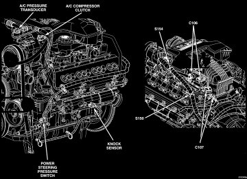
The 5.7L engine (Fig. 1)(345 CID) eight-cylinder engine is a 90° V-Type lightweight, deep skirt cast iron block, aluminum heads, single cam, overhead valve engine with hydraulic roller tappets. The heads incorporate splayed valves with a hemispherical style combustion chamber and dual spark plugs. The cyl- inders are numbered from front to rear; 1, 3, 5, 7 on the left bank and 2, 4, 6, 8 on the right bank. The firing order is 1-8-4-3-6-5-7-2.
DR
DIAGNOSIS AND TESTING
DIAGNOSIS AND TESTING - ENGINE DIAGNOSIS - INTRODUCTION Engine diagnosis is helpful
in determining the causes of malfunctions not detected and remedied by routine maintenance.
These malfunctions may be classified as either per- formance (e.g., engine idles rough and stalls) or mechanical (e.g., a strange noise).
Fig.15.7LENGINE
DR ENGINE - 5.7L (Continued)
(Refer to 9 - ENGINE - DIAGNOSIS AND TEST- ING)—PERFORMANCE and (Refer to 9 - ENGINE - DIAGNOSIS AND TESTING)—MECHANICAL for possible causes and corrections of malfunctions. (Refer to 14 - FUEL SYSTEM/FUEL DELIVERY - DIAGNOSIS AND TESTING) and (Refer to 14 - FUEL SYSTEM/FUEL INJECTION - DIAGNOSIS AND TESTING) for the fuel system diagnosis.
Additional tests and diagnostic procedures may be necessary for specific engine malfunctions that can not be isolated with the Service Diagnosis charts. Information concerning additional tests and diagno- sis is provided within the following diagnosis:
ENGINE - 5.7L
9 - 179
ENGINE - DIAGNOSIS AND TESTING).
† Cylinder Compression Pressure Test (Refer to 9 - † Cylinder Combustion Pressure Leakage Test (Refer to 9 - ENGINE - DIAGNOSIS AND TEST- ING).† Engine Cylinder Head Gasket Failure Diagnosis (Refer to 9 - ENGINE/CYLINDER HEAD - DIAGNO- SIS AND TESTING). † Intake Manifold Leakage Diagnosis (Refer to 9 -
MANIFOLD
ENGINE/MANIFOLDS/INTAKE DIAGNOSIS AND TESTING).
DIAGNOSIS AND TESTING - ENGINE DIAGNOSIS - PERFORMANCE
CONDITION
POSSIBLE CAUSE
CORRECTION
ENGINE WILL NOT START
1. Weak battery
1. Charge or replace as necessary.
2. Corroded or loose battery connections.
3. Faulty starter.
4. Faulty coil or control unit.
5. Incorrect spark plug gap.
6. Dirt or water in fuel system.
7. Faulty fuel pump, relay or wiring.
ENGINE STALLS OR ROUGH IDLE 1. Idle speed set to low.
2. Idle mixture too lean or too rich.
3. Vacuum leak.
4. Faulty coil.
5. Incorrect engine timing.
2. Clean and tighten battery connections. Apply a coat of light mineral grease to the terminals. 3. (Refer to 8 - ELECTRICAL/ STARTING - DIAGNOSIS AND TESTING). 4. (Refer to 8 - ELECTRICAL/ IGNITION CONTROL/IGNITION COIL - REMOVAL). 5. (Refer to 8 - ELECTRICAL/ IGNITION CONTROL/SPARK PLUG - CLEANING). 6. Clean system and replace fuel filter. 7. Repair or replace as necessary.
1. (Refer to 14 - FUEL SYSTEM/ FUEL INJECTION/IDLE AIR CONTROL MOTOR - REMOVAL). 2. Refer to Powertrain Diagnosis Information. 3. Inspect intake manifold and vacuum hoses, repair or replace as necessary. 4. (Refer to 8 - ELECTRICAL/ IGNITION CONTROL/IGNITION COIL - REMOVAL). 5. (Refer to 9 - ENGINE/VALVE TIMING - STANDARD PROCEDURE).
ENGINE - 5.7L
9 - 180
ENGINE - 5.7L (Continued)DR
CONDITION
POSSIBLE CAUSE
CORRECTION
1. ENGINE LOSS OF POWER
1. Dirty or incorrectly gapped spark plugs.
2. Dirt or water in fuel system.
3. Faulty fuel pump.
4. Blown cylinder head gasket. 5. Low compression.
6. Burned, warped or pitted valves. 7. Plugged or restricted exhaust system. 8. Faulty coil.
1. ENGINE MISSES ON ACCELERATION
1. Spark plugs dirty or incorrectly gapped.
2. Dirt in fuel system. 3. Burned, warped or pitted valves. 4. Faulty coil.
1. ENGINE MISSES AT HIGH SPEED
1. Spark plugs dirty or incorrectly gapped.
2. Faulty coil.
3. Dirt or water in fuel system.
1. (Refer to 8 - ELECTRICAL/ IGNITION CONTROL/SPARK PLUG - CLEANING). 2. Clean system and replace fuel filter. 3. (Refer to 14 - FUEL SYSTEM/ FUEL DELIVERY/FUEL PUMP - DIAGNOSIS AND TESTING). 4. Replace cylinder head gasket. 5. (Refer to 9 - ENGINE - DIAGNOSIS AND TESTING). 6. Replace as necessary. 7. Inspect and replace as necessary. 8. (Refer to 8 - ELECTRICAL/ IGNITION CONTROL/IGNITION COIL - REMOVAL).
1. (Refer to 8 - ELECTRICAL/ IGNITION CONTROL/SPARK PLUG - CLEANING). 2. Clean fuel system. 3. Replcae as necessary. 4. (Refer to 8 - ELECTRICAL/ IGNITION CONTROL/IGNITION COIL - REMOVAL).
1. (Refer to 8 - ELECTRICAL/ IGNITION CONTROL/SPARK PLUG - CLEANING). 2. (Refer to 8 - ELECTRICAL/ IGNITION CONTROL/IGNITION COIL - REMOVAL). 3. Clean system and replace fuel filter.
DR ENGINE - 5.7L (Continued) DIAGNOSIS AND TESTING - ENGINE DIAGNOSIS - MECHANICAL
ENGINE - 5.7L
9 - 181
CONDITION
POSSIBLE CAUSES
CORRECTIONS
NOISY VALVES
1. High or low oil level in crankcase.
2. Thin or diluted oil. 3. Low oil pressure.
4. Dirt in lash adjusters. 5. Worn rocker arms. 6. Worn lash adjusters 7. Worn valve guides.
8. Excessive runout of valve seats on valve faces.
CONNECTING ROD NOISE
1. Insufficient oil supply.
2. Low oil pressure.
3. Thin or diluted oil. 4. Excessive bearing clearance. 5. Connecting rod journal out-of-round. 6. Misaligned connecting rods.
MAIN BEARING NOISE
1. Insufficient oil supply.
2. Low oil pressure.
3. Thin or diluted oil. 4. Excessive bearing clearance. 5. Excessive end play. 6. Crankshaft journal out-of round. 7. Loose flywheel or torque converter.
1. (Refer to LUBRICATION & MAINTENANCE - SPECIFICATIONS)
2. Change oil and filter. 3. Check oil pump, if Ok, check rod and main bearings for excessive wear. 4. Replace as necessary. 5. Replace as necessary. 6. Replace as necessary. 7. (Refer to 9 - ENGINE/CYLINDER HEAD/INTAKE/EXHAUST VALVES & SEATS - STANDARD PROCEDURE) 8. (Refer to 9 - ENGINE/CYLINDER HEAD/INTAKE/EXHAUST VALVES & SEATS - STANDARD PROCEDURE)
1. (Refer to LUBRICATION & MAINTENANCE - SPECIFICATIONS)
2. Check oil pump, if Ok, check rod and main bearings for excessive wear. 3. Change oil and filter. 4. Replace as necessary. 5. Service or replace crankshaft.
6. Replace bent connecting rods.
1. (Refer to LUBRICATION & MAINTENANCE - SPECIFICATIONS) 2. Check oil pump, if Ok, check rod and main bearings for excessive wear. 3. Change oil and filter. 4. Replace as necessary. 5. Check thrust washers for wear. 6. Service or replace crankshaft. 7. Tighten to correct torque
ENGINE - 5.7L
9 - 182
ENGINE - 5.7L (Continued) DIAGNOSIS AND TESTING - CYLINDER COMPRESSION PRESSUREThe results of a cylinder compression pressure test can be utilized to diagnose several engine malfunc- tions.
Ensure the battery is completely charged and the engine starter motor is in good operating condition. Otherwise the indicated compression pressures may not be valid for diagnosis purposes.
(1) Clean the spark plug recesses with compressed
air.
(2) Remove the spark plugs. (3) Secure the throttle in the wide-open position. (4) Disable the fuel system (Refer to 14 - FUEL
SYSTEM/FUEL DELIVERY - DESCRIPTION).
(5) Remove the ASD relay (Refer to 8 - ELECTRI- CAL/IGNITION CONTROL/AUTO SHUT DOWN RELAY - REMOVAL).
(6) Insert a compression pressure gauge and rotate the engine with the engine starter motor for three revolutions.
(7) Record the compression pressure on the 3rd revolution. Continue the test for the remaining cylin- ders.
(8) (Refer to 9 - ENGINE - SPECIFICATIONS) for
the correct engine compression pressures.
DIAGNOSIS AND TESTING - CYLINDER COMBUSTION PRESSURE LEAKAGE
The combustion pressure leakage test provides an
accurate means for determining engine condition. Combustion pressure leakage testing will detect:
DR
† Exhaust and intake valve leaks (improper seat- ing).† Leaks between adjacent cylinders or into water jacket.† Any causes for combustion/compression pressure loss. (1) Check the coolant level and fill as required. DO
NOT install the radiator cap.
(2) Start and operate the engine until it attains normal operating temperature, then turn the engine OFF.
(3) Remove the spark plugs. (4) Remove the oil filler cap. (5) Remove the air cleaner hose. (6) Calibrate the tester according to the manufac- turer’s instructions. The shop air source for testing should maintain 483 kPa (70 psi) minimum, 1,379
kPa (200 psi) maximum and 552 kPa (80 psi) recom- mended.(7) Perform the test procedures on each cylinder according to the tester manufacturer’s instructions. Set piston of cylinder to be tested at TDC compres- sion,While testing, listen for pressurized air escaping through the throttle body, tailpipe and oil filler cap opening. Check for bubbles in the radiator coolant.
All gauge pressure indications should be equal,
with no more than 25% leakage.
FOR EXAMPLE: At 552 kPa (80 psi) input pres- sure, a minimum of 414 kPa (60 psi) should be main- tained in the cylinder.
Refer to CYLINDER COMBUSTION PRESSURE
LEAKAGE DIAGNOSIS CHART.
CYLINDER COMBUSTION PRESSURE LEAKAGE DIAGNOSIS CHART
CONDITION
AIR ESCAPES THROUGH THROTTLE BODY
POSSIBLE CAUSE
Intake valve bent, burnt, or not seated properly
AIR ESCAPES THROUGH TAILPIPE
Exhaust valve bent, burnt, or not seated properly
AIR ESCAPES THROUGH RADIATOR MORE THAN 50% LEAKAGE FROM ADJACENT CYLINDERS
MORE THAN 25% LEAKAGE AND AIR ESCAPES THROUGH OIL FILLER CAP OPENING ONLY
Head gasket leaking or cracked cylinder head or block Head gasket leaking or crack in cylinder head or block between adjacent cylinders Stuck or broken piston rings; cracked piston; worn rings and/or cylinder wall
CORRECTION
Inspect valve and valve seat. Reface or replace, as necessary. Inspect valve springs. Replace as necessary. Inspect valve and valve seat. Reface or replace, as necessary. Inspect valve springs. Replace as necessary. Remove cylinder head and inspect. Replace defective part Remove cylinder head and inspect. Replace gasket, head, or block as necessary Inspect for broken rings or piston. Measure ring gap and cylinder diameter, taper and out-of-round. Replace defective part as necessary
DR ENGINE - 5.7L (Continued) DIAGNOSIS AND TESTING—ENGINE DIAGNOSIS - LUBRICATION
ENGINE - 5.7L
9 - 183
CONDITION
OIL LEAKS
POSSIBLE CAUSES
CORRECTION
1. Gaskets and O-Rings.
1.
(a) Misaligned or damaged. (b) Loose fasteners, broken or porous metal parts. 2. Crankshaft rear seal 3. Crankshaft seal flange. Scratched, nicked or grooved. 4. Oil pan flange cracked. 5.Front cover seal, damaged or misaligned. 6. Scratched or damaged vibration damper hub.
(a) Replace as necessary. (b) Tighten fasteners, Repair or replace metal parts. 2. Replace as necessary. 3. Polish or replace crankshaft.
4. Replace oil pan. 5. Replace seal.
6. Polish or replace damper.
OIL PRESSURE DROP
1. Low oil level.
1. Check and correct oil level.
2. Faulty oil pressure sending unit. 3. Low oil pressure.
4. Clogged oil filter. 5. Worn oil pump. 6. Thin or diluted oil. 7. Excessive bearing clearance. 8. Oil pump relief valve stuck. 9. Oil pickup tube loose or damaged.
2. Replace sending unit. 3. Check pump and bearing clearance. 4. Replace oil filter. 5. Replace as necessary. 6. Change oil and filter. 7. Replace as necessary. 8. Replace oil pump. 9. Replace as necessary.
OIL PUMPING AT RINGS; SPARK
1. Worn or damaged rings.
PLUGS FOULING
2. Carbon in oil ring slots. 3. Incorrect ring size installed. 4. Worn valve guides. 5. Leaking intake gasket. 6. Leaking valve guide seals.
1. Hone cylinder bores and replace rings. 2. Replace rings. 3. Replace rings. 4. Ream guides and replace valves. 5. Replace intake gaskets. 6. Replace valve guide seals.
ENGINE - 5.7L
9 - 184
ENGINE - 5.7L (Continued) DIAGNOSIS AND TESTING - ENGINE DIAGNOSIS - MECHANICALENGINE MECHANICAL DIAGNOSIS CHART
DR
CONDITION
POSSIBLE CAUSES
CORRECTION
NOISY VALVES/LIFTERS
1. High or low oil level in crankcase
2. Thin or diluted oil
3. Low oil pressure
4. Dirt in tappets/lash adjusters
5. Bent push rod(s) 6. Worn rocker arms
7. Worn tappets/lash adjusters
8. Worn valve guides
9. Excessive runout of valve seats or valve faces
1. Insufficient oil supply 2. Low oil pressure
3. Thin or diluted oil
4. Excessive connecting rod bearing clearance
5. Connecting rod journal out of round 6. Misaligned connecting rods
1. Insufficient oil supply 2. Low oil pressure
3. Thin or diluted oil
CONNECTING ROD NOISE
MAIN BEARING NOISE
1. Check for correct oil level. Adjust oil level by draining or adding as needed 2. Change oil. (Refer to 9 - ENGINE/ LUBRICATION/OIL - STANDARD PROCEDURE) 3. Check engine oil level. If ok, Perform oil pressure test. (Refer to 9 - ENGINE/LUBRICATION - DIAGNOSIS AND TESTING) for engine oil pressure test/specifications 4. Clean/replace hydraulic tappets/ lash adjusters 5. Install new push rods 6. Inspect oil supply to rocker arms and replace worn arms as needed 7. Install new hydraulic tappets/lash adjusters 8. Inspect all valve guides and replace as necessary 9. Grind valves and seats
1. Check engine oil level. 2. Check engine oil level. If ok, Perform oil pressure test. (Refer to 9 - ENGINE/LUBRICATION - DIAGNOSIS AND TESTING) engine oil pressure test/specifications 3. Change oil to correct viscosity. (Refer to 9 - ENGINE/LUBRICATION/ OIL - STANDARD PROCEDURE) for correct procedure/engine oil specifications 4. Measure bearings for correct clearance with plasti-gage. Repair as necessary 5. Replace crankshaft or grind journals 6. Replace bent connecting rods
1. Check engine oil level. 2. Check engine oil level. If ok, Perform oil pressure test. (Refer to 9 - ENGINE/LUBRICATION - DIAGNOSIS AND TESTING) 3. Change oil to correct viscosity.
DR ENGINE - 5.7L (Continued)
ENGINE - 5.7L
9 - 185
CONDITION
POSSIBLE CAUSES
CORRECTION
LOW OIL PRESSURE
OIL LEAKS
4. Excessive main bearing clearance
5. Excessive end play
6. Crankshaft main journal out of round or worn 7. Loose flywheel or torque converter
1. Low oil level 2. Faulty oil pressure sending unit 3. Clogged oil filter 4. Worn oil pump 5. Thin or diluted oil 6. Excessive bearing clearance
7. Oil pump relief valve stuck
8. Oil pickup tube loose, broken, bent or clogged 9. Oil pump cover warped or cracked
1. Misaligned or deteriorated gaskets 2. Loose fastener, broken or porous metal part 3. Front or rear crankshaft oil seal leaking 4. Leaking oil gallery plug or cup plug
EXCESSIVE OIL CONSUMPTION OR SPARK PLUGS OIL FOULED
1. CCV System malfunction
2. Defective valve stem seal(s) 3. Worn or broken piston rings
4. Scuffed pistons/cylinder walls
5. Carbon in oil control ring groove 6. Worn valve guides
7. Piston rings fitted too tightly in grooves
4. Measure bearings for correct clearance. Repair as necessary 5. Check crankshaft thrust bearing for excessive wear on flanges 6. Grind journals or replace crankshaft
7. Inspect crankshaft, flexplate/ flywheel and bolts for damage. Tighten to correct torque
1. Check oil level and fill if necessary 2. Install new sending unit 3. Install new oil filter 4. Replace oil pump assembly. 5. Change oil to correct viscosity. 6. Measure bearings for correct clearance 7. Remove valve to inspect, clean and reinstall 8. Inspect oil pickup tube and pump, and clean or replace if necessary 9. Install new oil pump
1. Replace gasket 2. Tighten, repair or replace the part
3. Replace seal
4. Remove and reseal threaded plug. Replace cup style plug
1. (Refer to 25 - EMISSIONS CONTROL/EVAPORATIVE EMISSIONS - DESCRIPTION) for correct operation 2. Repair or replace seal(s) 3. Hone cylinder bores. Install new rings 4. Hone cylinder bores and replace pistons as required 5. Remove rings and de-carbon piston 6. Inspect/replace valve guides as necessary 7. Remove rings and check ring end gap and side clearance. Replace if necessary
ENGINE - 5.7L
9 - 186
ENGINE - 5.7L (Continued) STANDARD PROCEDURESTANDARD PROCEDURE - REPAIR DAMAGED OR WORN THREADS
CAUTION: Be sure that the tapped holes maintain the original center line.
Damaged or worn threads can be repaired. Essen- tially, this repair consists of: † Drilling out worn or damaged threads. † Tapping the hole with a special Heli-Coil Tap, or equivalent. † Installing an insert into the tapped hole to bring the hole back to its original thread size.
STANDARD PROCEDURE—HYDROSTATIC LOCK
CAUTION: DO NOT use the starter motor to rotate the crankshaft. Severe damage could occur.
When an engine is suspected of hydrostatic lock (regardless of what caused the problem), follow the steps below.
(1) Perform the Fuel Pressure Release Procedure (Refer to 14 - FUEL SYSTEM/FUEL DELIVERY - STANDARD PROCEDURE).
(2) Disconnect the negative cable(s) from the bat-
tery.
(3) Inspect air
induction system, and intake manifold to ensure system is dry and clear of foreign material.
cleaner,
(4) Place a shop towel around the spark plugs to catch any fluid that may possibly be under pressure in the cylinder head. Remove the spark plugs.
(5) With all spark plugs removed, rotate the crank-
shaft using a breaker bar and socket.
(6) Identify the fluid in the cylinders (coolant, fuel,
oil, etc.).
cylinders.
(8) Repair engine or components as necessary to
prevent this problem from occurring again.
(9) Squirt a small amount of engine oil into the cylinders to lubricate the walls. This will prevent damage on restart.
(10) Install new spark plugs. Tighten the spark
plugs to 41 N·m (30 ft. lbs.) torque.
(11) Drain engine oil. Remove and discard the oil
filter.
(12) Install the drain plug. Tighten the plug to 34