- Download PDF Manual
-
NOTE: The use of class “U” chains is permitted on the front and rear of 4X4, 3500 Ram Trucks with Dual Rear Wheels and LT235/80R17E tires. NOTE: On 4X2 2500/3500 Ram Trucks, class “U” snow chains are permitted on the rear wheels only of vehicles equipped with LT245/70R17, LT265/70R17, and LT235/ 80R17 size tires.
NOTE: On 4x4 2500/3500 SRW (Single Rear Wheel) Ram Trucks, class “U” snow chains are permitted on the rear wheels only of vehicles equipped with LT265/ 70R17E.
CAUTION!
Do not use tire chains on 4x4 Ram trucks equipped with P265/70R17, LT275/70R17, P275/60R20, or P275/ 55R20 tires. There may not be adequate clearance for the chains and you are risking structural or body damage to your vehicle. Do not use tire chains on the 4X2 front wheels of 2500/3500 SRW (Single Rear Wheels) equipped with LT245/70R17, LT265/70R17
LT235/80R17 tires or 4X4 front wheels of Ram Trucks equipped with LT265/70R17E. There may not be adequate clearance for the chains and you are risking structural or body damage to your vehicle.SNOW TIRES Snow tires should be of the same size and type construc- tion as the front tires. Consult the manufacturer of the snow tire to determine any maximum vehicle speed requirement associated with the tire. These tires should always be operated at the vehicle maximum capacity inflation pressures under any load condition. While studded tires improve performance on ice, skid and traction capability on wet or dry surfaces may be poorer than that of non-studded tires. Some states pro- hibit studded tires; local laws should be checked before using these tire types.
therefore,
STARTING AND OPERATING 253
TIRE ROTATION RECOMMENDATIONS Tires on the front and rear axles of vehicles operate at different loads and perform different steering, driving, and braking functions. For these reasons, they wear at unequal rates, and develop irregular wear patterns. These effects can be reduced by timely rotation of tires. The benefits of rotation are especially worthwhile with aggressive tread designs such as those on On/Off Road type tires. Rotation will increase tread life, help to main- tain mud, snow, and wet traction levels, and contribute to a smooth, quiet ride.
254 STARTING AND OPERATING
Follow the recommended tire rotation frequency for your type of driving found in the “Maintenance Schedules” Section of this manual. More frequent rotation is permis- sible if desired. The reasons for any rapid or unusual wear should be corrected prior to rotation being per- formed.
NOTE: On Canadian vehicles only, if your Ram truck is equipped with All-Season type tires on the front and ON/OFF Road type tires mounted on the rear, do not use a front to back rotation pattern. Instead, rotate your tires side to side at the recommended intervals.
Dual Rear Wheels
The tires used on dual wheel assemblies should be matched for wear to prevent overloading one tire in a set. To check if tires are even, lay a straight edge across all four tires. The straight edge should touch all the tires.
STARTING AND OPERATING 255
CAUTION!
3500 Dual Rear Tires have only one approved direc- tion of rotation. This is to accommodate the asym- metrical design (tread pattern) of the ON/OFF road tire and the use of Outline White Letter (OWL) tires. † When replacing a flat, the spare tire may have to be remounted on the rim or installed at a different location to maintain the correct placement of the tire on the wheel relative to the tire/wheel posi- tion on the truck. For example, if the spare is used to replace an outer rear tire it will have to be remounted on the rim so that the wheel is dished inward. That way the tread design of asymmetri- cal tires and the white writing of the OWL tires will maintain proper position.
256 STARTING AND OPERATING
FUEL REQUIREMENTS
All engines (except 5.7L engines) are de- signed to meet all emissions regulations and provide excellent fuel economy and performance when using high quality un- leaded “regular” gasoline having an oc- tane rating of 87. The routine use of pre- All Engines Except 5.7L mium gasoline is not recommended. Under normal conditions the use of premium fuel will not provide a benefit over high quality regular gasolines and in some circumstances may result in poorer perfor- mance.
The 5.7L engine is designed to meet all emissions regulations and provide satisfac- tory fuel economy and performance when using high quality unleaded gasoline hav- ing an octane range of 87 to 89. The manu- facturer recommends the use of 89 octane for optimum performance.The routine use
5.7L Engines
of premium gasoline is not recommended. The use of premium gasoline will provide no benefit over high quality regular and mid-grade gasolines, and in some circumstances may result in poorer performance. Light spark knock at low engine speeds is not harmful to your engine. However, continued heavy spark knock at high speeds can cause damage and immediate service is required. Engine damage resulting from operation with a heavy spark knock may not be covered by the new vehicle warranty. Poor quality gasoline can cause problems such as hard starting, stalling and hesitations. If you experience these symptoms, try another brand of “regular” gasoline be- fore considering service for the vehicle. Over 40 auto manufacturers world-wide have issued and endorsed consistent gasoline specifications (the World- wide Fuel Charter, WWFC) to define fuel properties necessary to deliver enhanced emissions, performance
and durability for your vehicle. We recommend the use of gasolines that meet the WWFC specifications if they are available. Reformulated Gasoline Many areas of the country require the use of cleaner burning gasoline referred to as “Reformulated Gasoline.” Reformulated gasolines contain oxygenates, and are spe- cifically blended to reduce vehicle emissions and im- prove air quality. We strongly support the use of reformulated gasolines. Properly blended reformulated gasolines will provide excellent performance and durability for the engine and fuel system components.
STARTING AND OPERATING 257
Gasoline/Oxygenate Blends Some fuel suppliers blend unleaded gasoline with oxy- genates such as 10% ethanol, MTBE and ETBE. Oxygen- ates are required in some areas of the country during the winter months to reduce carbon monoxide emissions. Fuels blended with these oxygenates may be used in your vehicle.
CAUTION!
DO NOT use gasolines containing METHANOL. Gasoline containing methanol may damage critical fuel system components.
258 STARTING AND OPERATING
MMT In Gasoline MMT is a manganese-containing metallic additive that is blended into some gasoline to increase octane. Gasolines blended with MMT provide no performance advantage beyond gasolines of the same octane number without MMT. Gasolines blended with MMT reduce spark plug life and reduce emission system performance. We recom- mend that gasolines free of MMT be used in your vehicle. The MMT content of gasoline may not be indicated on the gasoline pump; therefore, you should ask your gaso- line retailer whether or not his/her gasoline contains MMT. It is even more important to look for gasolines without MMT in Canada because MMT can be used at levels higher than allowed in the United States. MMT is pro- hibited in Federal and California reformulated gasolines.
Sulfur In Gasoline If you live in the northeast United States, your vehicle may have been designed to meet California low emission standards with Cleaner-Burning California reformulated gasoline with low sulfur. If such fuels are not available in states adopting California emission standards, your ve- hicles will operate satisfactorily on fuels meeting federal specifications, but emission control system performance may be adversely affected. Gasoline sold outside of California is permitted to have higher sulfur levels which may affect the performance of the vehicle’s catalytic converter. This may cause the Check Engine or Service Engine Soon light to illuminate. We recommend that you try a different brand of unleaded gasoline having lower sulfur to determine if the problem is fuel related prior to returning your vehicle to an authorized dealer for ser- vice.
STARTING AND OPERATING 259
CAUTION!
CAUTION!
If the Check Engine or Service Engine Soon light is flashing, immediate service is required; see onboard diagnostics system section.
To avoid fuel spillage and overfilling, do not “top off” the fuel tank after filling.
Materials Added To Fuel All gasolines sold in the United States are required to contain effective detergent additives. Use of additional detergents or other additives is not needed under normal conditions and would result in unnecessary cost. There- fore, you should not have to add anything to the fuel. ADDING FUEL
If fuel is poured from a portable container, the NOTE: container should have a flexible nozzle long enough to extend into the fuel filler tube.
NOTE: When the fuel nozzle “clicks” or shuts off, the fuel tank is full. NOTE: Tighten the gas cap until you hear a “clicking” sound. This is an indication that the gas cap is properly tightened. Make sure that the gas cap is tightened each time the vehicle is refueled.
WARNING!
A fire may result if gasoline is pumped into a portable container that is inside of a vehicle or on a truck bed. You could be burned. Always place gas containers on the ground while filling.
260 STARTING AND OPERATING
Fuel Filler Cap (Gas Cap) The gas cap is behind the fuel filler door. If the gas cap is lost or damaged, be sure the replacement cap is for use with this vehicle.
CAUTION!
Damage to the fuel system or emission control system could result from using an improper fuel tank filler tube cap (gas cap). A poorly fitting cap could let impurities into the fuel system.
WARNING!
† Remove the fuel tank filler tube cap (gas cap) slowly to prevent fuel spray from the filler neck which may cause injury. † The volatility of some gasolines may cause a buildup of pressure in the fuel tank that may increase while you drive. This pressure can result in a spray of gasoline and/or vapors when the cap is removed from a hot vehicle. Removing the cap slowly allows the pressure to vent and prevents fuel spray. † Never allow any lit smoking materials near the vehicles while removing the cap or filling the tank. † Never add fuel to the vehicle when the engine is
running.
Fuel System Cautions
CAUTION!
Follow these guidelines to maintain your vehicle’s performance: † The use of leaded gas is prohibited by Federal law. Using leaded gasoline can impair engine performance, damage the emission control system, and could result in loss of warranty coverage. † An out-of-tune engine, or certain fuel or ignition malfunctions, can cause the catalytic converter to overheat. If you notice a pungent burning odor or some light smoke, your engine may be out of tune or malfunctioning and may require immediate service. Contact your dealer for service assistance.
STARTING AND OPERATING 261
† When pulling a heavy load or driving a fully loaded vehicle when the humidity is low and the temperature is high, use a premium unleaded fuel to help prevent spark knock. If spark knock persists, lighten the load, or engine piston damage may result. † The use of fuel additives which are now being sold as octane enhancers is not recommended. Many of these products contain high concentrations of methanol. Fuel system damage or vehicle performance problems resulting from the use of such fuels or additives is not the responsibility of the manufacturer and may not be covered under the New Vehicle Warranty.
NOTE: systems can result against you.
Intentional tampering with emissions control in civil penalties being assessed
262 STARTING AND OPERATING
Carbon Monoxide Warnings
WARNING!
Carbon monoxide (CO) in exhaust gases is deadly. Follow the precautions below to prevent carbon monoxide poisoning: † Do not inhale exhaust gases. They contain carbon monoxide, a colorless and odorless gas which can kill. Never run the engine in a closed area, such as a garage, and never sit in a parked vehicle with the engine running for an extended period. If the vehicle is stopped in an open area with the engine running for more than a short period, adjust the ventilation system to force fresh, outside air into the vehicle. † Guard against carbon monoxide with proper mainte- nance. Have the exhaust system inspected every time
the vehicle is raised. Have any abnormal conditions repaired promptly. Until repaired, drive with all side windows fully open. † Keep the liftgate closed when driving your vehicle to prevent carbon monoxide and other poisonous ex- haust gases from entering the vehicle.
FLEXIBLE FUEL—(Fleet Vehicles Only)
E-85 General Information The information in this section is for Flexible Fuel ve- hicles only. These vehicles can be identified by the unique fuel filler door label that states Ethanol (E-85) or Un- leaded Gasoline Only. This section only covers those subjects that are unique to these vehicles. Please refer to the other sections of this manual for information on features that are common between Flexible Fuel and gasoline only powered vehicles.
CAUTION!
Only vehicles with the E-85 fuel filler door label can operate on E-85.
ETHANOL FUEL (E-85) E-85 is a mixture of approximately 85% fuel ethanol and 15% unleaded gasoline.
WARNING!
Ethanol vapors are extremely flammable and could cause serious personal injury. Never have any smok- ing materials lit in or near the vehicle when remov- ing the fuel filler tube cap (gas cap) or filling the tank. Do not use E-85 as a cleaning agent and never use it near an open flame.
STARTING AND OPERATING 263
Fuel Requirements Your vehicle will operate on both unleaded gasoline with an octane rating of 87, or E-85 fuel, or any mixture of these two. For best results, a refueling pattern that alternates be- tween E-85 and unleaded gasoline should be avoided. When you do switch fuels, it is recommended that † you do not switch when the fuel gauge indicates less † you do not add less than 5 gallons when refueling † you operate the vehicle immediately after refueling for
than 1/4 full
a period of at least 5 minutes
Observing these precautions will avoid possible hard starting and/or significant deterioration in drivability during warm up.
264 STARTING AND OPERATING
NOTE: When the ambient temperature is above 90°F, you may experience hard starting and rough idle follow- ing start up even if the above recommendations are followed. Selection Of Engine Oil For best performance and protection of your vehicle, use only crankcase engine oils that meet the following re- quirements: † Engine Oil Selection for Operating on E-85
(P/N 4318086) or an equivalent
If you operate the vehicle on E-85 fuel either full or part-time, use only Mopar Flexible Fuel 5W-30 engine oil that meets DaimlerChrysler Standard MS-9214. Equivalent com- mercial Flexible Fuel engine oils may be labeled as Flexible Fuel (FFV) or Alternate Fuel (AFV). These engine oils may be satisfactory if the DaimlerChrysler Standard.
they meet
The 5W-30 engine oil installed at the factory meets the DaimlerChrysler requirements for Flexible Fuel engine oil. SAE 5W-30 engine oil is preferred for use in Flexible Fuel engines.
CAUTION!
If Flexible Fuel engine oil is not used when using E-85, engine wear may be increased significantly. This may void your warranty. † Engine Oil Selection for Operating on Gasoline If you operate the vehicle on regular unleaded gasoline ONLY, use Mopar oil or an equivalent that meets certified API (American Petroleum Institute) Quality.
Starting The characteristics of E-85 fuel make it unsuitable for use when ambient temperatures fall below 0°F. In the range of 0°F to 32°F, you may experience an increase in the time it takes for your engine to start, and a deterioration in drivability (sags and/or hesitations) until the engine is fully warmed up. Cruising Range Because E-85 fuel contains less energy per gallon than gasoline, you will experience an increase in fuel con- sumption. You can expect your MPG and your driving range to decrease by about 30% compared to gasoline operation. Replacement Parts Many components in your Flexible Fuel Vehicle (FFV) are designed to be compatible with ethanol. Always be sure that your vehicle is serviced with correct ethanol com- patible parts.
STARTING AND OPERATING 265
CAUTION!
Replacing fuel system components with non-ethanol compatible components can damage your vehicle and may void the warranty.
Maintenance If you operate the vehicle using E-85 fuel, follow Sched- ule B in the maintenance schedule section of this manual.
CAUTION!
Do not use ethanol mixture greater than 85% in your vehicle. It will cause difficulty in cold starting and may affect driveability.
266 STARTING AND OPERATING
CATALYTIC CONVERTER The catalytic converter requires the use of unleaded fuel only. Leaded gasoline will destroy the effectiveness of the catalyst as an emission control device. Under normal operating conditions, the catalytic converter will not require maintenance. However, you must keep the en- gine maintained to assure proper operation and prevent possible damage. NOTE: systems can result against you.
Intentional tampering with emissions control in civil penalties being assessed
CAUTION!
Damage to the catalytic converter can result if your vehicle is not kept in proper operating condition. In the event of engine malfunction, particularly involv- ing engine misfire or other apparent loss of perfor- mance, have your vehicle serviced promptly. Contin- ued operation of your vehicle with a severe malfunction could cause the converter to overheat, resulting in possible damage to the converter and vehicle.
As with any vehicle, do not park or operate this vehicle in areas where combustible materials such as grass or leaves can come in contact with a hot exhaust system. A scorching odor may be detected if you continue to run a malfunctioning engine. The odor may indicate severe and abnormal catalyst overheating. If this occurs, the
vehicle should be stopped, the engine shut off and the vehicle allowed to cool. Service, including a tune-up to manufacturer’s specifications should be obtained imme- diately. To minimize the possibility of catalyst damage: † Do not try to start the engine by pushing or towing the † Do not idle the engine with any spark plug wires † Do not idle the engine for prolonged periods during very rough idle or malfunctioning operating condi- tions.
disconnected or removed.
vehicle.
† Do not allow vehicle to run out of fuel.
STARTING AND OPERATING 267
VEHICLE LOADING
Certification Label As required by National Highway Traffic Safety Admin- istration Regulations, your vehicle has a certification label affixed to the driver’s side door or pillar. This label contains the month and year of manufacture, Gross Vehicle Weight Rating (GVWR), Gross Axle Weight Rating (GAWR) front and rear, and Vehicle Identification Number (VIN). A Month-Day-Hour (MDH) number is included on this label and indicates the Month, Day and Hour of manufacture. The bar code that appears on the bottom of the label is your Vehicle Identification Number (VIN). Gross Vehicle Weight Rating (GVWR) The GVWR is the total permissible weight of your vehicle including driver, passengers, vehicle, options and cargo. The label also specifies maximum capacities of front and
268 STARTING AND OPERATING
rear axle systems (GAWR). Total load must be limited so GVWR and front and rear GAWR are not exceeded. Payload The payload of a vehicle is defined as the allowable load weight a truck can carry, including the weight of the driver, all passengers, options and cargo. Gross Axle Weight Rating (GAWR) The GAWR is the maximum permissible load on the front and rear axles. The load must be distributed in the cargo area so that the GAWR of each axle is not exceeded. Each axle GAWR is determined by the components in the system with the lowest load carrying capacity (axle, springs, tires or wheels). Heavier axles or suspension components sometimes specified by purchasers for in- creased durability does not necessarily increase the vehi- cle’s GVWR.
Tire Size This is the minimum allowable tire size for your vehicle. Replacement tires must be equal to the load capacity of this tire size. Rim Size This is the rim size that is appropriate for the tire size listed. Inflation Pressure This is the cold tire inflation pressure for your vehicle for all loading conditions up to full GAWR. Curb Weight The curb weight of a vehicle is defined as the total weight of the vehicle with all fluids, including vehicle fuel, at full capacity conditions, and with no occupants or cargo loaded into the vehicle. The front and rear curb weight values are determined by weighing your vehicle on a commercial scale before any occupants or cargo are added.
Loading The actual total weight and the weight of the front and rear of your vehicle at the ground can best be determined by weighing it when it is loaded and ready for operation. The entire vehicle should first be weighed on a commer- cial scale to insure that the GVWR has not been exceeded. The weight on the front and rear of the vehicle should then be determined separately to be sure that the load is properly distributed over front and rear axle. Weighing the vehicle may show that the GAWR of either the front or rear axles has been exceeded but the total load is within the specified GVWR. If so, weight must be shifted from front to rear or rear to front as appropriate until the specified weight limitations are met. Store the heavier items down low and be sure that the weight is distributed equally. Stow all loose items securely before driving.
STARTING AND OPERATING 269
Improper weight distributions can have an adverse effect on the way your vehicle steers and handles and the way the brakes operate.
CAUTION!
Do not load your vehicle any heavier than the GVWR or the maximum front and rear GAWR. If you do, parts on your vehicle can break, or it can change the way your vehicle handles. This could cause you to lose control. Also overloading can shorten the life of your vehicle.
An EXAMPLE of a loaded vehicle is shown in the following chart. Note that neither GVWR nor GAWR capabilities are exceeded. Overloading can cause poten- tial safety hazards and shorten service life.
270 STARTING AND OPERATING
NOTE: The weights shown in this chart are not necessarily the weights for your vehicle. Also, the amount of load added to both the front and rear axles can be computed after the vehicle has been weighed both in its (curb weight( condition, and in its (loaded and ready for operation( condition. Gross Vehicle Weight Rating (GVWR) 6500 LBS.
TRAILER TOWING All Dodge Ram Pickup trucks are intended to tow trailers up to 2,000 lbs (907 kg) without added equipment or alterations to standard equipment. Your vehicle may be factory equipped for safe towing of trailers weighing over 2,000 lbs (907 kg) with the optional Trailer Tow Prep Package. See your Dodge dealer for package content. To Maintain Warranty Coverage Follow the requirements and recommendations in this manual concerning vehicles used for trailer towing. Definitions The following trailer towing related terminology defini- tions will assist in understanding the subsequent sec- tions: GROSS COMBINATION WEIGHT RATING (GCWR) is the total permissible weight of your vehicle and trailer when weighed in combination. (Note that GCWR ratings
include a 150 lb (68 kg) allowance for the presence of a driver.) Tongue Weight (of a trailer) is the weight placed on a vehicle’s trailer hitch by the trailer. GROSS TRAILER WEIGHT (GTW) is the weight of the trailer plus the weight of all cargo, consumables and equipment (permanent or temporary) loaded in or on the trailer in its 9loaded and ready for operation9 condition. TRAILER SWAY CONTROL is a telescoping link that can be installed between the hitch receiver and the trailer tongue that typically provides adjustable friction associ- ated with the telescoping motion to dampen any un- wanted trailer swaying motions while traveling.
STARTING AND OPERATING 271
CAUTION!
† During the first 500 miles (805 km) your new vehicle is driven, do not tow a trailer. Doing so may damage your vehicle. † When first towing a trailer, limit your speed to 50
mph (80 km/h) during the first 500 miles (805 km) of towing.Consider the following items when computing the weight on the rear axle: † the tongue weight of the trailer † the weight of any other type of cargo or equipment put
in or on your vehicle
272 STARTING AND OPERATING
NOTE: Remember that everything put into or on the trailer adds to the load on your vehicle. Also, additional factory-installed options, or dealer-installed options, must be considered as part of the total load on your vehicle. Refer to the Certification label located at the driver’s door for the Gross Vehicle Weight Rating.
WARNING!
Improper towing can lead to an injury accident. Follow these guidelines to make your trailer towing as safe as possible:
Perform the maintenance listed in the “Maintenance Schedules” section of this manual (Section 8). When towing a trailer, never exceed the Gross Axle Weight Rating (GAWR), or Gross Combined Vehicle Weight (GCVW).
CAUTION!
When hauling cargo or towing a trailer, do not overload your vehicle or trailer. Overloading can cause a loss of control, poor performance or damage to brakes, axle, engine, transmission, steering, sus- pension, body structure or tires.
Axle Lubricant and Trailer Towing 1500 Models † 1500 Model rear axles are trailer tow ready. Limited slip rear axles on 1500 models require the use of a limited slip additive (refer to the “Recommended Fluids, Lubricants, and Genuine Parts” section.) † The limited slip additive is included with the factory † If the axle fluid is changed, 4 oz. (118 ml) of limited slip
fill.
additive must be added.
2500/3500 Models † The Axles on 2500/3500 Models are trailer tow ready and DO NOT REQUIRE any special axle lubes or additives.
your vehicle.
vehicle and trailer.
Trailer Towing Recommendations † All trailer hitches should be professionally installed on † Safety chains must always be used between your † Do not interconnect the hydraulic brake system or vacuum system of your vehicle with that of the trailer. This could cause inadequate braking and possible personal injury. An electrically–actuated electric trailer brake controller is recommended.
STARTING AND OPERATING 273
† Trailer brakes are recommended for trailers over 1000
lbs (454 kg) and are required for trailers in excess of 2,000 lbs (907 kg) † Use an approved wiring harness connector on the trailer. Standard equipment on all RAM pickup mod- els provides a 4-way trailer tow connector located under the bumper. This connector contains the follow- ing vehicle circuits: park/tail lamps, left stop/turn lamp, right stop/turn lamp, and ground. With the optional Trailer Tow Prep package a 7-way connector is provided with the following additional circuits: backup lamp, trailer battery and electric brake.NOTE: Connect trailer lighting and brakes using factory harnesses only. Do not cut or splice wiring to the brake circuits.
274 STARTING AND OPERATING
† Be sure the trailer is loaded heavier in front, with 60% to 65% of the weight in front of the axle(s). Loads balanced over the wheels or heavier in the rear can cause the trailer to sway severely side to side which will cause loss of control of vehicle and trailer. Failure to load trailers heavier in front is the cause of many trailer accidents. (For a 95th Wheel9 style trailer, this range of loading on the 9King Pin9 should be between 15% and 25%.) † Make certain that the load is secured in the trailer and will not shift during travel. When towing cargo such as livestock, dynamic load shifts can occur that require the driver to maintain attention.
Trailer Towing — Hitches With a Class I Hitch, your vehicle can be equipped to tow trailers with a Gross Trailer Weight (GTW) of 2,000 lbs (907 kg) maximum.
With a Class II Hitch, your vehicle can be equipped to tow trailers with a Gross Trailer Weight (GTW) of 3,500
lbs (1 587 kg ) maximum. Tongue weight must be equal to at least 10% of GTW, but no more than 15% of GTW. With a Class III Hitch, your vehicle can be equipped to tow trailers with a Gross Trailer Weight (GTW) of 5,000
lbs (2 268 kg) maximum. Factory-installed rear step bumpers are rated a Class III hitch. A frame mounted hitch of up to Class IV rating, as rated by the hitch manufacturer, may also be installed. With a Class IV Hitch, you can tow a trailer with a Gross Trailer Weight of up to 12,000 lbs (5 443 kg) maximum depend- ing on your vehicle equipment.Connecting Trailer Lighting And Electric Trailer Brakes
NOTE: A 4-way trailer tow connector, located behind the bumper, is standard equipment on all Ram pickup models. This connector contains the following vehicle circuits: park/tail lamps, left stop/turn lamp, right stop/ turn lamp, and ground. With the optional Trailer Tow Prep package a 7-way connector is also provided with the following additional circuits: backup lamp, trailer battery and electric brake. NOTE: There is also a 4–way connector located under the instrument panel, located to the left of the brake pedal that is used for the electric brake. This connector contains the following vehicle circuits; power ground, battery, stop lamp switch and electric brake feed. The 4–way is optional with the trailer tow prep package.
STARTING AND OPERATING 275
CAUTION!
Adding lights or electrical devices to the headlamp/ park lamp circuit can be accomplished by connecting to the standard 4-way trailer tow connector located behind the rear bumper. The maximum current ca- pacity for the park lamp circuit should not exceed 15
amps total (a typical park lamp bulb can draw from 0.5 to 1.0 amperes of current). No connections can be made to the headlamp switch itself, because it is not designed for high current applications. Connections to the headlamp switch will cause the exterior lights to malfunction.276 STARTING AND OPERATING
CAUTION!
Connect trailer lighting and brakes using factory harnesses only. Do not cut or splice wiring to the brake circuits. Use an approved wiring harness con- nector on the trailer.
Trailer Weight and Trailer Tongue Weight Gross Trailer Weight (GTW) means the weight of the trailer plus the weight of all cargo, consumables and equipment loaded on the trailer when in actual under- way towing condition. The recommended way to mea- sure GTW is to put your fully loaded trailer on a vehicle scale. The entire weight of the trailer must be supported by the scale. Tongue Weight is the weight placed on the vehicle’s trailer hitch by the trailer. Always load a trailer with 60%
to 65% of the weight in the front of the trailer. This places 10% to 15% of the GTW on the tow hitch of your vehicle. Trailer sway control and equalizing hitch are required for Class III or IV trailer hitches and tongue weights above 350 lbs (159 kg).
Tongue weight must be equal to at least 10% of GTW, but no more than 15% of GTW.
Also, there are maximum tongue weight ratings that are not to be exceeded, as follows: † Class III (the bumper ball type) 500 lbs (227 kg) † Class IV (the receiver hitch type) 1200 lbs (544 kg) NOTE: When towing a trailer, the following require- ments must be adhered to: † GCWR must not be exceeded † Total weight must be distributed between the tow vehicle and the trailer such that the following four (4) ratings are not exceeded: 1. GVWR 2. GTW 3. Tongue weight rating for the trailer hitch utilized (This requirement may limit the ability to always
STARTING AND OPERATING 277
achieve the 10% to 15% range of tongue weight [15% to 25% for a (5th Wheel( style trailer] as a percentage of total trailer weight.) 4. GAWR ratings
Trailer Towing Information (Maximum Trailer Weight Ratings) (Trailer Towing Guide( NOTE: For trailer towing information (maximum trailer weight ratings) refer to the following website address: http:// www.dodge.com/towing. In Canada, refer to the following website address: http:// www.dodge.ca.
278 STARTING AND OPERATING
Trailer Towing Mirrors — If Equipped These mirrors are designed with an adjustable mirror head to provide a greater vision range when towing extra-wide loads. To change position inboard or out- board, the mirror head should be rotated (flipped Out or In). A small blindspot mirror is integrated onto the main mirror surface.
Cooling System Tips — Trailer Towing To reduce potential for engine and transmission over- heating, take the following actions: † City Driving— when stopped, put the transmission in † Highway Driving— reduce your speed.
N (Neutral) and increase the engine idle speed.
† Air Conditioning— turn it off temporarily. † Hilly Terrain— Turn overdrive off. See Cooling System Operating information in the Service and Maintenance section of this manual for more infor- mation. Automatic Transmission Oil Temperature Warning Light All vehicles with automatic transmissions are equipped with a transmission sump oil temperature sensor and warning light. If elevated transmission temperatures are encountered, the engine controller will select the most desirable gear until the transmission temperatures are reduced. If transmission oil temperatures continue to rise, a warning light located in the instrument cluster will illuminate. If this should occur, stop the vehicle, shift to Neutral, and run the engine at idle or faster until the light goes off.
STARTING AND OPERATING 279
Towing With An Automatic Transmission Vehicles equipped with an automatic transmission may shift into and out of Overdrive, or a lower gear, when driving in hilly areas, when heavily loaded, or when towing into heavy winds. When this condition occurs, select TOW/HAUL mode or shift into a lower gear to prevent excessive transmission wear and/or overheating, and to provide better engine braking. NOTE: Do not exceed the following RPM while manu- ally downshifting: † 5800 rpm with 3.7L engines. † 5800 rpm with 4.7L engines. † 5600 rpm with 5.7L engines.
280 STARTING AND OPERATING
If your vehicle has an automatic transmission and you tow a trailer frequently, change transmission fluid and filter every 30,000 miles (48 000 km)
SNOWPLOW Snowplow Prep Packages are available as a factory installed option. These packages include components necessary to equip your vehicle with a snowplow. Dodge Ram 1500 Models
NOTE: Do not use Dodge Ram 1500 Models for snow- plow applications.
WARNING!
On 1500 Models, snowplows, winches, and other aftermarket equipment should not be added to the front end of your vehicle. The airbag crash sensors may be affected by the change in the front end structure. The airbags could deploy unexpectedly or could fail to deploy during a collision resulting in serious injury or death.
CAUTION!
Using 1500 Model vehicles for snowplow applica- tions can cause damage to the vehicle.
NOTE: Before installation of a snowplow it is highly recommended that the owner / installer obtain and follow the recommendations contained within the Dodge
2004 BODY BUILDER’S GUIDE. See your dealer, installer or snowplow manufacture for this information. There are unique electrical systems that must be connected to properly assure operator safety and prevent overloading vehicle systems that would void the vehicle warranty.
WARNING!
Attaching a snowplow to this vehicle could ad- versely affect performance of the airbag system in an accident. Do not expect that the airbag will perform as described earlier in this manual
CAUTION!
The “Lamp Out” indicator could illuminate if exte- rior lamps are not properly installed.
STARTING AND OPERATING 281
level.
Before plowing † Check the hydraulic system for leaks and proper fluid † Check the mounting bolts and nuts for proper tight- † Check the runners and cutting edge for excessive wear. The cutting edge should be 1/4 to 1/2 inch (6.4 mm to13 mm) above ground in snow plowing position. † Check that snowplow lighting is connected and func-
ness.
tioning properly.
Snowplow Model Prep Package Availability For Detailed Information Visit www.dodge.com or refer to the 2004 Dodge Truck Body Builders Guide. 1. The 1500 models are NOT available for snowplow applications.
282 STARTING AND OPERATING
2. The maximum number of occupants in the truck should not exceed two. 3. The total GVWR or the Front GAWR or the Rear GAWR should never be exceeded. 4. The snowplow prep packages are not available with the Sport Package. 5. Cargo capacity will be reduced by the addition of options or passengers, etc. The loaded vehicle weight, including the snowplow system, all aftermarket accessories, driver, passengers, options, and cargo, must not exceed either the Gross Vehicle Weight (GVWR) or Gross Axle Weight (GAWR) ratings. These weights are specified on the Safety Com- pliance Certification Label on the driver’s side door opening. NOTE: passengers.
Detach the snowplow when transporting
if necessary at
Vehicle front end wheel alignment was set to specifica- tions at the factory without consideration for the weight of the plow. Front end tow-in should be checked and reset the beginning and end of the snowplow season. This will help prevent uneven tire wear. The blade should be lowered whenever the vehicle is parked. Maintain and operate your vehicle and snowplow equip- ment following the recommendations provided by the specific snowplow manufacturer. Over the Road Operation With Snowplow Attached The blade restricts air flow to the radiator and causes the engine to operate at higher than normal temperatures. Therefore, when transporting the plow, angle the blade completely and position it as low as road or surface
conditions permit. Do not exceed 40 mph (64 km/h). The operator should always maintain a safe stopping distance and allow adequate passing clearance. Methods For Removing Snow
STARTING AND OPERATING 283
Operating Tips Under ideal snow plowing conditions, 20 mph (32 km/h) should be maximum operating speed. The operator should be familiar with the area and surface to be cleaned. Reduce speed and use extreme caution when plowing unfamiliar areas or under poor visibility. NOTE: During snowplow usage on vehicles equipped with an overhead console module, the outside tempera- ture display will show higher temperatures than the outside ambient temperature. The higher displayed tem- perature is due to blocked or reduced airflow to the underhood ambient temperature sensor by the snow- plow. This is common and outside temperature display operation will return to normal when the snowplow is removed.
284 STARTING AND OPERATING
General Maintenance Snowplows should be maintained in accordance with the plow manufacturer’s instructions. Whenever the plow is disconnected from the vehicle, coat the exposed angling cylinder rods with chassis lubricant. The lift cylinder should be extended upward and chassis lubricant ap- plied to the lift rod. The hydraulic hoses interconnect to keep the couplers clean. Keep all snowplow electrical connections and battery terminals clean and free of corrosion. When plowing snow, to avoid transmission and driv- etrain damage, the following precautions should be ob- served. † Operate with transfer case in 4L when plowing small or congested areas where speeds are not likely to exceed 15 mph (24 km/h). At higher speeds operate in 4H.
† Do not shift the transmission unless the engine has returned to idle and wheels have stopped. Make a practice of stepping on the brake pedal before shifting the transmission.
RECREATIONAL TOWING — 4–WHEEL DRIVE VEHICLES (BEHIND MOTORHOME, ETC.)
CAUTION!
Internal damage to the transfer case will occur if a front or rear wheel lift is used when recreational towing.
NOTE: Both the Manual Shift and Electronic Shift transfer cases must be shifted into Neutral (N) for recreational towing. Automatic transmissions must be placed in P (Park) position for recreational towing. Manual transmissions must be left in gear (not in neutral)
for recreational towing. Refer below for the proper trans- fer case Neutral shifting procedure for your vehicle. Recreational Towing Procedure — Manual Shift Transfer Case — If Equipped Use the following procedure to prepare your vehicle for recreational towing:
CAUTION!
It is necessary to follow these steps to be certain that the transfer case is fully in N (NEUTRAL) before recreational towing to prevent damage to internal parts.
1. Bring the vehicle to a complete stop. 2. Shut OFF the engine. 3. Depress the brake pedal.
STARTING AND OPERATING 285
4. Shift automatic transmission to N (NEUTRAL), or depress the clutch on manual transmissions. 5. Shift transfer case lever into N (NEUTRAL). 6. Start the engine. 7. Shift automatic transmission into Reverse (R). 8. Release brake pedal for five seconds and ensure that there is no vehicle movement. 9. Repeat steps 7 and 8 with the transmission in Drive (D). 10. Shut OFF the engine and place the ignition key to the unlocked OFF position. 11. Shift automatic transmission into P (PARK). 12. Apply the parking brake. 13. Attach vehicle to tow vehicle with tow bar. 14. Release the parking brake.
286 STARTING AND OPERATING
CAUTION!
Damage to the automatic transmission may occur if the transmission is shifted into P (PARK) with the transfer case in N (NEUTRAL) and the engine RUN- NING. With the transfer case in N (NEUTRAL) ensure that the engine is OFF prior to shifting the transmission into P (PARK)
Returning to Normal Operation — Manual Shift Transfer Case Use the following procedure to prepare your vehicle for normal usage: 1. Bring the vehicle to a complete stop. 2. Shut OFF the engine. 3. Depress the brake pedal.
4. Shift automatic transmission to N (NEUTRAL), or depress the clutch on manual transmissions. 5. Shift transfer case lever to desired position. 6. Shift automatic transmission into P (Park).
WARNING!
You or others could be injured if you leave the vehicle unattended with the transfer case in the N (NEUTRAL) position without first fully engaging the parking brake. The transfer case N (NEUTRAL) position disengages both the front and rear drive- shafts from the powertrain and will allow the ve- hicle to move regardless of the transmission posi- tion. The parking brake should always be applied when the driver is not in the vehicle.
CAUTION!
† Do not use a bumper mounted clamp-on tow bar on your vehicle. The bumper face bar will be damaged. † Do not disconnect the rear driveshaft because fluid will leak from the transfer case and damage the internal parts.
Recreational Towing Procedure — Electronic Shift Transfer Case — If Equipped
Use the following procedure to prepare your vehicle for recreational towing.
STARTING AND OPERATING 287
CAUTION!
It is necessary to follow these steps to be certain that the transfer case is fully in Neutral (N) before recreational towing to prevent damage to internal parts.
1. Bring vehicle to a complete stop. 2. Shut OFF the engine. 3. Place ignition key in the ON position. 4. Depress the brake pedal. 5. Shift automatic transmission to Neutral (N) or depress clutch on manual transmission. 6. Using the point of a ballpoint pen or similar object, depress the recessed transfer case Neutral (N) button for 4 seconds.
288 STARTING AND OPERATING
7. After shift is completed and the Neutral (N) light comes on release Neutral (N) button. 8. Start engine. 9. Shift automatic transmission into Reverse (R). 10. Release brake pedal for five seconds and ensure that there is no vehicle movement. 11. Repeat steps 9 and 10 with the transmission in Drive (D). 12. Shut engine OFF and place ignition key to the unlocked OFF position. 13. Shift automatic transmission into Park (P). 14. Apply parking brake. 15. Attach vehicle to tow vehicle with tow bar. 16. Release parking brake.
Items 1 through 5 are requirements that must be NOTE: met prior to depressing the Neutral (N) selection button, and must continue to be met until the 4 seconds elaspes and the shift has been completed. If any of these require- ments (with the exception of 3 - Key ON) are not met prior to depressing the Neutral (N) button or are no longer met during the 4 second timer, then the Neutral (N) indicator light will flash continuously until all re- quirements are met or until the Neutral (N) button is released. NOTE: The ignition key must be ON for a shift to take place and for the position indicator lights to be operable. If the key in not ON, the shift will not take place and no position indicator lights will be on or flashing. NOTE: Flashing neutral (N) position indicator light indicates that shift requirements have not been met.
CAUTION!
Damage to the transmission may occur if the trans- mission is shifted into Park (P) with the transfer case in Neutral (N) and the engine RUNNING. With the transfer case in Neutral (N) ensure that the engine is OFF prior to shifting the transmission into Park (P).
Returning to Normal Operation — Electronic Shift Transfer Case
Use the following procedure to prepare your vehicle for normal usage. 1. Bring vehicle to a complete stop. 2. Shut OFF the engine. 3. Place ignition key in the ON position. 4. Depress the brake pedal.
STARTING AND OPERATING 289
5. Shift automatic transmission to Neutral (N) or depress clutch on manual transmission. 6. Using the point of a ballpoint pen or similar object, depress the recessed transfer case Neutral (N) button for 1 second. 7. After the Neutral (N) indicator light turns off release the Neutral (N) button. 8. After the Neutral (N) button has been released the transfer case will shift to the position identified by the selector switch. 9. Shift automatic transmission into P (Park). Items 1 through 5 are requirements that must be NOTE: met prior to depressing the Neutral (N) selection button, and must continue to be met until 1 second elapses and the shift has been completed. If any of these requirements (with the exception of 3 - key ON) are not met prior to depressing the Neutral (N) button or are no longer met
290 STARTING AND OPERATING
during the 1 second time, then all of the mode position indicator lights will flash continuously until all require- ments are met or until the Neutral (N) button is released. NOTE: The ignition key must be ON for a shift to take place and for the position indicator lights to be operable. If the key is not ON, the shift will not take place and no position indicator lights will be on or flashing. NOTE: Flashing neutral (N) position indicator light indicates that shift requirements have not been met.
WARNING!
You or others could be injured if you leave the vehicle unattended with the transfer case in the Neutral (N) position without first fully engaging the parking brake. The transfer case Neutral (N) position disengages both the front and rear driveshafts from the powertrain and will allow the vehicle to move despite the transmission position. The parking brake should always be applied when the driver is not in the vehicle.
CAUTION!
† Do not use a bumper mounted clamp-on tow bar on your vehicle. The bumper face bar will be damaged. † Do not disconnect the rear driveshaft because fluid will leak from the transfer case and fluid loss will damage internal parts.
DRIVING OFF-ROAD Care should be taken when attempting to climb steep hills or driving diagonally across a hill or slope. If natural obstacles force you to travel diagonally up or down a hill, choose a mild angle and keep as little side tilt as possible. Keep the vehicle moving and make turns slowly and cautiously.
STARTING AND OPERATING 291
If you must back down a hill, back straight down using REVERSE gear. Never back down in NEUTRAL, or diagonally across the hill. When driving over sand, mud, and other soft terrain, shift to low gear and drive steadily. Apply the accelerator slowly to avoid spinning the wheels. DO NOT REDUCE the tire pressures for this type of driving. NOTE: After off-road usage, particularly in sand or mud, inspect the underside of the vehicle for accumu- lated dirt at the propeller shaft, axles, U-joints, brake rotors and calipers. Use a hose to clean off any accumulation of dirt or mud. Check the exhaust system and all exposed components for any sign of damage.
292 STARTING AND OPERATING
If you experience unusual vibration after driving in mud, slush or similar conditions, check the wheels for im- pacted material. Impacted foreign material can cause a wheel imbalance. Removing the foreign material from the wheels will correct the situation.
TRACTION When driving on wet or slushy roads, it is possible for a wedge of water to build up between the tire and road surface. This is known as hydroplaning and may cause partial or complete loss of vehicle control and stopping ability. To reduce this possibility, the following precau- tions should be observed: 1. Slow down during rainstorms or when roads are slushy. 2. Slow down if road has standing water or puddles. 3. Replace tires when tread wear indicators first become visible.
4. Keep tires properly inflated. 5. Maintain sufficient distance between your vehicle and the car in front to avoid a collision in a sudden stop.
EQUIPMENT IDENTIFICATION PLATE The equipment Identification Plate is located on the hood inner surface. The following information about your vehicle is dis- played on this plate: Model, Wheelbase, Vehicle Identifi- cation Number, Truck Order Number, and code numbers with descriptions of all production and special equip- ment on the truck as shipped from the factory. NOTE: Always refer to the Equipment Identification Plate When Ordering Parts.
WHAT TO DO IN EMERGENCIES
CONTENTS
m Hazard Warning Lights . . . . . . . . . . . . . . . . . . 294
m Adding Fuel . . . . . . . . . . . . . . . . . . . . . . . . . . 295
m Jack Location . . . . . . . . . . . . . . . . . . . . . . . . . . 296
N Removal (All Models) . . . . . . . . . . . . . . . . . . 296
N Reinstalling The Scissors-Type Jack And Tools(1500 Models) . . . . . . . . . . . . . . . . . . . . . . . . 298
m Changing A Flat Tire . . . . . . . . . . . . . . . . . . . . 301
N Removing The Spare Tire . . . . . . . . . . . . . . . . 301
N Tire Changing Procedure . . . . . . . . . . . . . . . . 302m Hoisting . . . . . . . . . . . . . . . . . . . . . . . . . . . . . 312
m Jump-Starting . . . . . . . . . . . . . . . . . . . . . . . . . 312
m Freeing A Stuck Vehicle . . . . . . . . . . . . . . . . . . 316
m Emergency Tow Hooks — If Equipped . . . . . . . . 316
m Towing A Disabled Vehicle . . . . . . . . . . . . . . . . 317
N 4-Wheel- Drive Vehicles . . . . . . . . . . . . . . . . . 317
N 2–Wheel- Drive Vehicles . . . . . . . . . . . . . . . . 317294 WHAT TO DO IN EMERGENCIES
HAZARD WARNING LIGHTS The Hazard Warning switch is mounted on the top of the steering column as shown in the illustration.
To engage the Hazard Warning lights, depress the button on the top of the steering column. When the Hazard Warning switch is activated, all directional turn signals
will flash off and on to warn oncoming traffic of an emergency. Push the button a second time to turn off the flashers. This is an emergency warning system and should not be used when the vehicle is in motion. Use it when your vehicle is disabled and is creating a safety hazard for other motorists. When you must leave the vehicle to seek assistance, the Hazard Warning lights will continue to operate even though the ignition switch is OFF. NOTE: With extended use, the Hazard Warning lights may discharge your battery.
ADDING FUEL The fuel tank filler tube has a restricting door about 2
inches (50 mm) inside the opening. If using a portable fuel container, it should have a flexible nozzle long enough to force open the restricting door.WARNING!
A fire may result if gasoline is pumped into a portable container that is in a vehicle or on a truck bed. You could be burned. Always place gas contain- ers on the ground while filling.
WHAT TO DO IN EMERGENCIES 295
WARNING!
Remove the gas cap slowly to prevent fuel spray from the filler neck which may cause injury. The volatility of present gasolines may cause a build up of pressure in the fuel tank that may increase while you drive. This pressure can result in a spray of gasoline and/or vapors when you remove the cap from a hot vehicle. Removing the cap slowly allows the pressure to vent and prevents fuel spray. Never allow any lit smoking materials near the vehicles while removing the cap or filling the tank. Never add fuel to the vehicle when the engine is running.
296 WHAT TO DO IN EMERGENCIES
JACK LOCATION
Removal (All Models) The jack and jack tools are stored under the front passenger seat. Lift the flap on the side of the seat for access. Remove the jack and tools by removing the wing bolt and sliding the assembly from under the seat.
1500 Model Vehicles
WHAT TO DO IN EMERGENCIES 297
WARNING!
The jack is designed to use as a tool for changing tires only. The jack should not be used to lift the vehicle for service purposes, unless suitable sup- ports are placed under the vehicle as a safety mea- sure. The vehicle should be jacked on a firm level surface only. Avoid ice or slippery areas.
WARNING!
After using the jack and tools, always reinstall them in the original carrier and location. While driving you may experience, abrupt stopping, rapid accelera- tion, or sharp turns. A loose jack, tools, bracket or other objects in the vehicle may move around with force, resulting in serious injury.
2500/3500 Model Vehicles
298 WHAT TO DO IN EMERGENCIES
Reinstalling The Scissors-Type Jack And Tools (1500 Models)
1. Lower the jack all the way down by turning the jack turn-screw until the jack is snug. 2. Position the jack and tool bag (unrolled). Make sure the lug wrench is under the jack near the jack turn-screw.
Turn Screw and Lug Wrench Position
3. Fold the flap and roll the jack tool kit into a cylindrical package (in direction of arrows), and tie to the jack using the tie straps.
WHAT TO DO IN EMERGENCIES 299
Tying Bag to Jack with Straps
Folding Flap and Rolling Bag
300 WHAT TO DO IN EMERGENCIES
Jack and Tools Tied Together
1500 Model Vehicles
4. Place the jack and tools in the storage position holding the jack by the jack turn-screw, slip the jack and tools under seat so that the bottom slot engages into the fastener on the floor and then secure to the floor pan using the wing bolt.
CHANGING A FLAT TIRE
Removing The Spare Tire Remove the spare tire before attempting to jack the truck. Attach the wheel wrench to the jack extension tube. Insert the tube through the access hole between the lower tailgate and the top of the bumper and into the winch mechanism tube. Rotate the wheel wrench handle coun- terclockwise until the spare tire is on the ground with enough cable slack to allow you to pull it out from under the vehicle. When the spare is clear, tilt the retainer at the end of the cable and pull it through the center of the wheel.
WHAT TO DO IN EMERGENCIES 301
It is recommended that you stow the flat or spare to avoid tangling the loose cable. NOTE: The winch mechanism is designed for use with the jack extension tube only. Use of an air wrench or other power tools is not recommended and can damage the winch.
302 WHAT TO DO IN EMERGENCIES
Tire Changing Procedure
WARNING!
Getting under a jacked-up vehicle is dangerous. The vehicle could slip off the jack and fall on you. You could be crushed. Never get any part of your body under a vehicle that is on a jack. Never start or run the engine while the vehicle is on a jack. If you need to get under a raised vehicle, take it to a service center where it can be raised on a lift.
Do not raise this vehicle using a bumper jack. The jack is designed as a tool for changing tires on this vehicle only. It is not recommended that the jack be used for service purposes or to lift more than one wheel at a time.
Preparations Park the vehicle on a firm level surface, avoiding ice or slippery areas. Set the parking brake and place the gear selector in PARK (automatic transmission) or REVERSE (manual transmission). On four-wheel drive vehicles, shift the transfer case to the “4L” position.
WARNING!
Do not attempt to change a tire on the side of the vehicle close to moving traffic. Pull far enough off the road to avoid the danger of being hit when operating the jack or changing the wheel.
† Turn on the Hazard Warning Flasher.
† Block both the front and rear of the wheel diagonally oppo- site the jacking position. For example, front wheel is being changed, block the left rear wheel. † Passengers should not remain in the vehicle when the
the right
if
vehicle is being jacked.
WHAT TO DO IN EMERGENCIES 303
Instructions
WARNING!
be raised.
Carefully follow these tire changing warnings to help prevent personal injury or damage to your vehicle: † Always park on a firm, level surface as far from the edge of the roadway as possible before raising the vehicle. † Block the wheel diagonally opposite the wheel to † Apply the parking brake firmly before jacking. † Never start the engine with the vehicle on a jack. † Do not let anyone sit in the vehicle when it is on a † Do not get under the vehicle when it is on a jack. † Only use the jack in the positions indicated. † If working on or near a roadway, be extremely
jack.
careful of motor traffic.
304 WHAT TO DO IN EMERGENCIES
1. Remove the spare wheel, jack, and tools from storage. 2. Using the wheel wrench, loosen, but do not remove, the wheel nuts by turning them counterclockwise one turn while the wheel is still on the ground. 3. Placement of the Jack: † For 1500 series trucks, when changing a front wheel, place the scissors jack under the rear portion of the lower control arm as shown below.
1500 4X2 Jacking Location
WHAT TO DO IN EMERGENCIES 305
1500 4X4 Jacking Location
† For 2500/3500 4x2 series trucks, when changing a front wheel, place the bottle jack under the frame rail behind the wheel. Locate the jack as far forward as possible on the straight part of the frame.
2500/3500 4X2 Jacking Location
† Operate the jack using the jack drive tube and the wheel wrench. The tube extension, may be used, but is not required. † For 2500/3500 4x4 series trucks, when changing the front wheel, assemble the jack drive tube to the jack and connect the drive tube to the extension tube.
306 WHAT TO DO IN EMERGENCIES
Place the jack under the axle as close to the tire as possible with the drive tubes extending to the front. Connect the jack tube extension and wheel wrench.
under the axle between the spring and the shock absorber with the drive tubes extending to the rear.
2500/3500 4X4 Jacking Location
† For all trucks, when changing a rear wheel, as- semble the jack drive tube to the jack and connect the drive tube to the extension tube. Place the jack
Rear Jacking Location (All)
† Connect the jack tube extension and wheel wrench. Before raising the wheel off the ground, make sure that the jack will not damage surrounding truck parts and adjust the jack position as required.
If the 2500/3500 bottle jack will not lower by NOTE: turning the dial (thumb wheel) by hand, it may be necessary to use the jack drive tube in order to lower the jack. 4. By rotating the wheel wrench clockwise, raise the vehicle until the wheel just clears the surface.
WARNING!
Raising the vehicle higher than necessary can make the vehicle unstable and cause an accident. It could slip off the jack and hurt someone near it. Raise the vehicle only enough to remove the tire.
5. Remove the wheel nuts and pull the wheel off. Install the spare wheel and wheel nuts with the cone shaped end
WHAT TO DO IN EMERGENCIES 307
of the nuts toward the wheel on 2500/3500 single rear wheel (SRW) models. On 3500 dual rear wheel models (DRW) the lug nuts are a two piece assembly with a flat face. Lightly tighten the nuts. To avoid risk of forcing the vehicle off the jack, do not fully tighten the nuts until the vehicle has been lowered. 6. Using the wheel wrench, finish tightening the nuts using a crisscross pattern. Correct nut tightness is 135 ft. lbs. (183 N·m) torque for 2500/3500 single rear wheel (SRW) models and 145 ft. lbs. (197 N·m) for 3500 dual rear wheel models. If in doubt about the correct tightness, have them checked with a torque wrench by your dealer or at a service station.
308 WHAT TO DO IN EMERGENCIES
WARNING!
A loose tire or jack thrown forward in a collision or hard stop could injure someone in the vehicle. Always stow the jack parts and the extra tire and wheel in the places provided.
7. Install wheel center cap and remove wheel blocks. Do not install chrome or aluminum wheel center caps on the spare wheel. This may result in cap damage. 8. Lower the jack to its fully closed position. If the bottle jack will not lower by turning the dial (thumb wheel) by hand, it may be necessary to use the jack drive tube in order to lower the jack. Stow the replaced tire, jack, and tools as previously described. 9. Adjust the tire pressure when possible.
NOTE: Do not oil wheel studs. For chrome wheels, do not substitute with chrome plated wheel nuts. Hub Caps The hub caps must be removed before raising the vehicle off the ground. For 2500/3500 single rear wheel (SRW) models, use the blade on the end of the lug wrench to pry the cap off. On 3500 models with dual rear wheels (DRW), you must first remove the hub caps. The jack handle driver has a hook at one end that will fit in the pry off notch of the rear hub caps. Position the hook and pull out on the ratchet firmly. The cap should pop off. The wheel skins can now be removed. For the front hub cap on 3500
models use the blade on the end of the lug wrench to pry the caps off. The wheel skin can now be removed. You must use the flat end of the lug wrench to pry off the wheel skins. Insert the flat tip completely and using aback and forth motion, loosen the wheel skin. Repeat this procedure around the tire until the skin pops off. Replace the wheel skins first using a rubber mallet. When replacing the hub caps, tilt the cap retainer over the lugnut bolt circle and strike the high side down with a rubber mallet. Be sure that the hub caps and wheel skins are firmly seated around the wheel. 8-Stud — Dual Rear Wheels Dual wheels are flat mounted, center piloted. The lug nuts are a two piece assembly. When the tires are being rotated or replaced, clean these lug nuts and add 2 drops of oil at the interface between the hex and the washer.
WHAT TO DO IN EMERGENCIES 309
Slots in the wheels will assist in properly orienting the inner and outer wheels. Align these slots when assem- bling the wheels for best access to the tire valve on the inner wheel. The tires of both dual wheels must be completely off the ground when tightening to insure wheel centering and maximum wheel clamping.
310 WHAT TO DO IN EMERGENCIES
Dual wheel models require a special heavy-duty lug nut tightening adapter (included with the vehicle) to cor- rectly tighten the lug nuts. Also, when it is necessary to remove and install dual rear wheels, use a proper vehicle lifting device. NOTE: When installing a spare tire as part of a dual rear wheel end combination, the tire diameter of the two individual tires must be compared. If there is a significant difference, the larger tire should be installed in a front location. Correct direction of rotation for dual tire instal- lations must also be observed. These dual rear wheels should be tightened as follows:
1. Tighten the wheel nuts in the numbered sequence to a snug fit. 2. Retighten the wheel nuts in the same sequence to the torques listed in the table. Go through the sequence a second time to verify that specific torque has been achieved. Retighten to specifications at 100 miles (160
km) and after 500 miles (800 km). It is recommended that wheel stud nuts be kept torqued to specifications at all times. Torque wheel stud nuts to specifications at each lubrication interval. Wheel Nuts All wheel nuts should be tightened occasionally to elimi- nate the possibility of wheel studs being sheared or the bolt holes in the wheels becoming elongated. This is especially important during the first few hundred miles of operation to allow the wheel nuts to become properly set. All nuts should first be firmly seated against theWHAT TO DO IN EMERGENCIES 311
wheel. The nuts should then be tightened to recom- mended torque. Tighten the nuts to final torque in increments. Progress around the bolt circle, tightening the nut opposite to the nut just previously tightened until final torque is achieved. Recommended torques are shown in the following chart. Disc Wheels
Type Nut Stud Size Torque Ft. Lbs.
Cone Cone Flanged
1/2-20
9/16-18
9/16-1890-110
120-150
130-160To Stow The Flat Or Spare Turn the wheel so that the valve stem is down. Slide the wheel retainer through the center of the wheel and position it properly across the wheel opening. For convenience in checking the spare tire inflation, stow with the valve stem toward the rear of the vehicle.
Torque Newton Meters 100-150
160-200
190-220312 WHAT TO DO IN EMERGENCIES
Attach the wheel wrench to the extension tube. Rotate the winch mechanism until the wheel is drawn into place against the underside of the vehicle. Continue to rotate until you feel the winch mechanism slip or click 3 or 4
times. It cannot be overtightened. Push against the tire several times to be sure it is firmly in place.HOISTING A conventional floor jack may be used at the jacking locations, refer to the graphics that show jacking loca- tions. However, a floor jack or frame hoist must never be used on any other parts or the underbody.
CAUTION!
Never use a floor jack directly under the differential housing of a loaded truck or damage to your vehicle may result.
JUMP-STARTING You should not try to start your vehicle by pushing or towing. Vehicles equipped with an automatic transmis- sion cannot be started this way and pushing or towing a vehicle equipped with a manual transmission may over- heat and damage the catalytic converter. Also, there is a greater risk of an accident when a vehicle is being pushed or towed. If the vehicle has a discharged battery, booster cables may be used to obtain a start from a booster battery or the battery in another vehicle. This type of start can be dangerous if done improperly, so follow this procedure carefully.
WARNING!
Battery fluid is a corrosive acid solution; do not allow battery fluid to contact eyes, skin or clothing. Don’t lean over battery when attaching clamps or allow the clamps to touch each other. If acid splashes in eyes or on skin, flush contaminated area immedi- ately with large quantities of water. A battery generates hydrogen gas which is flam- mable and explosive. Keep flame or spark away from the vent holes. Do not use a booster battery or any other booster source that has a greater than 12 volt system, i.e. Do not use a 24 volt power source.
Check the Battery Test Indicator (If Equipped). If a yellow or bright colored dot is visible in the indicator (if equipped), DO NOT jump-start the battery.
WHAT TO DO IN EMERGENCIES 313
If the indicator (if equipped) is dark or shows a green dot, proceed as follows: 1. Remove all metal jewelry such as watch bands or bracelets which might make an unintended electrical contact. 2. Park the booster vehicle within cable reach but with- out letting the vehicles touch. Set the parking brake on
314 WHAT TO DO IN EMERGENCIES
both vehicles, place the automatic transmission in Park or the manual transmission in Neutral, and turn the ignition OFF. 3. Turn off the heater, radio, and all unnecessary electri- cal loads. 4. Connect one end of a jumper cable to the positive terminal of the booster battery. Connect the other end of the same cable to the positive terminal of the discharged battery.
WARNING!
Do not permit vehicles to touch each other as this could establish a ground connection and personal injury could result.
5. Connect the other cable, first to the negative terminal of the booster battery and then to the engine of the vehicle with the discharged battery. Make sure you have a good contact on the engine.
WARNING!
† Do not connect the cable to the negative post of the discharge battery. The resulting electrical spark could cause the battery to explode. † During cold weather when temperatures are be- low freezing point, electrolyte in a discharged battery may freeze. Do not attempt jump starting because the battery could rupture or explode. The battery temperature must be brought up above freezing point before attempting jump start.
WHAT TO DO IN EMERGENCIES 315
6. Start the engine in the vehicle which has the booster battery, let the engine idle a few minutes, then start the engine in the vehicle with the discharged battery. 7. When removing the jumper cables, reverse the above sequence exactly. Be careful of the moving belts and fan.
WARNING!
Any procedure other than above could result in: 1. Personal injury caused by electrolyte squirting out the battery vent; 2. Personal injury or property damage due to battery explosion; 3. Damage to charging system of booster vehicle or of immobilized vehicle.
316 WHAT TO DO IN EMERGENCIES
FREEING A STUCK VEHICLE If vehicle becomes stuck in snow, sand, or mud, it can often be moved by a rocking motion. Move the gear selector rhythmically between DRIVE and REVERSE, while applying slight pressure to the accelerator. In general, the least amount of accelerator pedal pressure to maintain the rocking motion without spinning the wheels or racing the engine is most effective. Racing the engine or spinning the wheels, due to the frustration of not freeing the vehicle, may lead to transmission over- heating and failure. Allow the engine to idle with the transmission selector in NEUTRAL for at least one minute after every five rocking-motion cycles. This will minimize overheating and reduce the risk of transmis- sion failure during prolonged efforts to free a stuck vehicle.
EMERGENCY TOW HOOKS — IF EQUIPPED Your vehicle may be equipped with emergency tow hooks.
WARNING!
Chains are not recommended for freeing a stuck vehicle. Chains may break, causing serious injury or death.
WARNING!
Stand clear of vehicles when pulling with tow hooks. Tow straps and chains may break, causing serious injury.
CAUTION!
4-Wheel- Drive Vehicles
WHAT TO DO IN EMERGENCIES 317
Tow hooks are for emergency use only, to rescue a vehicle stranded off road. Do not use tow hooks for tow truck hookup or highway towing. You could damage your vehicle.
CAUTION!
To avoid damage to the transfer case while towing, always use one of the following methods.
TOWING A DISABLED VEHICLE Proper towing or lifting equipment is required to prevent damage to your vehicle. Use only tow bars and other equipment designed for the purpose, following equip- ment manufacturer’s instructions. Use of safety chains is mandatory. Attach a tow bar or other towing device to the main structural members of the vehicle—not to bumpers or associated brackets. State and local laws applying to vehicles under tow must be observed.
The manufacturer recommends towing with all wheels off the ground. Acceptable methods are to tow vehicle on a flatbed or with one end of vehicle raised and the opposite end on a towing dolly. 2–Wheel- Drive Vehicles Provided that the transmission is operable, tow with the transmission in Neutral and the ignition key in the OFF position along with the front wheels raised and the rear wheels on the ground. Speed must not exceed 30 mph (50
km/h) and distance must not exceed 15 miles (25 km).318 WHAT TO DO IN EMERGENCIES
If the vehicle is to be towed more than 15 miles (25 km) the vehicle must be towed with the rear wheels raised and the front wheels on the ground. It may also be towed on a flatbed or with the front wheels raised and the rear wheels on a dolly.
MAINTAINING YOUR VEHICLE
CONTENTS
m Engine Compartment— 3.7L/4.7L . . . . . . . . . . . 322
m Engine Compartment— 5.7L . . . . . . . . . . . . . . . 323
m Onboard Diagnostic System (OBD II) . . . . . . . . . 324
m Emissions Inspection And MaintenancePrograms
. . . . . . . . . . . . . . . . . . . . . . . . . . . . 324
m Dealer Service . . . . . . . . . . . . . . . . . . . . . . . . . 326
m Replacement Parts . . . . . . . . . . . . . . . . . . . . . . 327
m Maintenance Procedures . . . . . . . . . . . . . . . . . . 327
N Air Conditioner Maintenance . . . . . . . . . . . . . 327N Engine Oil . . . . . . . . . . . . . . . . . . . . . . . . . . 329
N Engine Oil Filter . . . . . . . . . . . . . . . . . . . . . . 333
N Drive Belts — Check Condition AndTensioner . . . . . . . . . . . . . . . . . . . . . . . . . . . 333
N Spark Plugs . . . . . . . . . . . . . . . . . . . . . . . . . 333
N Engine Air Cleaner Filter . . . . . . . . . . . . . . . . 334
N Engine Fuel Filter . . . . . . . . . . . . . . . . . . . . . 334
N Catalytic Converter . . . . . . . . . . . . . . . . . . . . 335
N Emission-Related Components . . . . . . . . . . . . 336320 MAINTAINING YOUR VEHICLE
N Maintenance Free Battery . . . . . . . . . . . . . . . . 337
N Air Conditioner Maintenance . . . . . . . . . . . . . 338
N Power Steering — Fluid Check . . . . . . . . . . . . 339
N Front Suspension Ball Joints . . . . . . . . . . . . . . 340
N Steering Linkage — Inspection . . . . . . . . . . . . 341
N Half-Shaft Constant Velocity Joints . . . . . . . . . 341
N Body Lubrication . . . . . . . . . . . . . . . . . . . . . 341
N Windshield Wiper Blades . . . . . . . . . . . . . . . . 342
N Windshield Washers . . . . . . . . . . . . . . . . . . . 342
N Exhaust System . . . . . . . . . . . . . . . . . . . . . . 343
N Cooling System . . . . . . . . . . . . . . . . . . . . . . . 344
N Hoses And Vacuum/Vapor Harnesses . . . . . . . 347
N Brake System . . . . . . . . . . . . . . . . . . . . . . . . 348N Clutch Hydraulic System . . . . . . . . . . . . . . . . 349
N Clutch Linkage . . . . . . . . . . . . . . . . . . . . . . . 350
N Propeller Shaft Universal Joints . . . . . . . . . . . 350
N Rear Axle And 4X4 Front Driving AxleFluid Level . . . . . . . . . . . . . . . . . . . . . . . . . . 350
N Transfer Case . . . . . . . . . . . . . . . . . . . . . . . . 351
N Manual Transmission . . . . . . . . . . . . . . . . . . 351
N Automatic Transmission . . . . . . . . . . . . . . . . 352
N Front Wheel Bearings . . . . . . . . . . . . . . . . . . 355
N Selection Of Lubricating Grease . . . . . . . . . . . 356
N Noise Control System Required Maintenance & Warranty For 3500 2-Wheel Drive And 4-Wheel Drive Models Over 10,000 Lbs. (4 535 Kg) Gross Vehicle Weight Rating. . . . . . . . . . . . . . . . . . . 356N Appearance Care And Protection From
Corrosion . . . . . . . . . . . . . . . . . . . . . . . . . . . 361
m Fuse And Relay Center . . . . . . . . . . . . . . . . . . . 365
m Vehicle Storage . . . . . . . . . . . . . . . . . . . . . . . . 365
m Replacement Light Bulbs . . . . . . . . . . . . . . . . . 366
m Bulb Replacement . . . . . . . . . . . . . . . . . . . . . . 366N Headlight (Halogen)/Front Park And Turn
Lights . . . . . . . . . . . . . . . . . . . . . . . . . . . . . 366
N Tail, Stop, Turn And Backup Lights . . . . . . . . . 370
N Center High-Mounted Stoplight With CargoLight . . . . . . . . . . . . . . . . . . . . . . . . . . . . . . 372
MAINTAINING YOUR VEHICLE 321
N Cab Top Clearance Lights — If Equipped . . . . 374
N Tailgate ID Lights (Dual Rear Wheels) . . . . . . . 375
N Side Marker Lights (Dual Rear Wheels) . . . . . . 377
N Fog Lights . . . . . . . . . . . . . . . . . . . . . . . . . . 378
. . . . . . . . . . . . . . . . . . . 379m Fluids And Capacities m Recommended Fluids, Lubricants And Genuine
Parts . . . . . . . . . . . . . . . . . . . . . . . . . . . . . . . . 381
N Engine . . . . . . . . . . . . . . . . . . . . . . . . . . . . . 381
N Chassis . . . . . . . . . . . . . . . . . . . . . . . . . . . . 382322 MAINTAINING YOUR VEHICLE
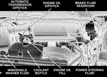
ENGINE COMPARTMENT— 3.7L/4.7L
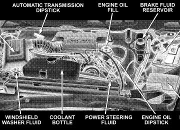
ENGINE COMPARTMENT— 5.7L
MAINTAINING YOUR VEHICLE 323
324 MAINTAINING YOUR VEHICLE
ONBOARD DIAGNOSTIC SYSTEM (OBD II) Your vehicle is equipped with a sophisticated onboard diagnostic system called OBD II. This system monitors the performance of the emissions, engine, and automatic transmission control systems. When these systems are operating properly, your vehicle will provide excellent performance and fuel economy, as well as engine emis- sions well within current government regulations. If any of these systems require service, the OBD II system will turn on the “Malfunction Indicator Light.” It will also store diagnostic codes and other information to assist your service technician in making repairs. Al- though your vehicle will usually be driveable and not need towing, see your dealer for service as soon as possible.
CAUTION!
Prolonged driving with the “Malfunction Indicator Light” on could cause further damage to the emis- sion control system. It could also affect fuel economy and driveability. The vehicle must be serviced before any emissions tests can be performed. If the “Malfunction Indicator Light” is flashing, severe catalytic converter damage and power loss will soon occur. Immediate service is required.
EMISSIONS INSPECTION AND MAINTENANCE PROGRAMS In some localities, it may be a legal requirement to pass an inspection of your vehicle’s emissions control system. Failure to pass could prevent vehicle registration.
For states which have an I/M (Inspection and Maintenance) requirement, this check verifies the following: the MIL (Malfunction Indicator Lamp) is functioning and is not on when the engine is running, and that the OBD (On Board Diagnostic) system is ready for testing. Normally, the OBD system will be ready. The OBD system may not be ready if your vehicle was recently serviced, if you recently had a dead battery, or a battery replacement. If the OBD system should be determined not ready for the I/M test, your vehicle may fail the test. Your vehicle has a simple ignition key actuated test which you can use prior to going to the test station. To check if your vehicle’s OBD system is ready, you must do the following: 1. Insert your ignition key into the ignition switch.
MAINTAINING YOUR VEHICLE 325
2. Turn the ignition to the ON position, but do not crank or start the engine. 3. If you crank or start the engine, you will have to start this test over. 4. As soon as you turn your key to the ON position, you will see your MIL symbol come on as part of a normal bulb check. 5. Approximately 15 seconds later, one of two things will happen:
a. The MIL light will blink for approximately 5 sec- onds and then remain on until the first engine crank or the key is turned off. This means that your vehicle’s OBD system is not ready and you should not proceed to the I/M station.
326 MAINTAINING YOUR VEHICLE
b. The MIL light will remain fully illuminated until the first engine crank or the key is turned off. This means that your vehicle’s OBD system is ready and you can proceed to the I/M station.
If your OBD system is not ready, you should see your dealer or repair facility. If your vehicle was recently serviced or had a battery failure or replacement, you may need to do nothing more than drive your vehicle as you normally would in order for your OBD system to update. A recheck with the above test routine may then indicate that the system is now ready. Regardless of whether your vehicle’s OBD system is ready or not ready, if the MIL symbol is illuminated during normal vehicle operation, you should have your vehicle serviced before going to the I/M station. The I/M station can fail your vehicle because the MIL symbol is on with the engine running.
DEALER SERVICE Your dealer has the qualified service personnel, special tools and equipment to perform all service operations in an expert manner. Service manuals are available which include detailed service information for your vehicle. Refer to these manuals before attempting any procedure yourself. NOTE: systems can result against you.
Intentional tampering with emissions control in civil penalties being assessed
WARNING!
You can be badly injured working on or around a motor vehicle. Do only that service work for which you have the knowledge and the proper equipment. If you have any doubt about your ability to perform a service job, take your vehicle to a competent mechanic.
REPLACEMENT PARTS Use of genuine Mopart parts for normal/scheduled maintenance and repairs is highly recommended to in- sure the designed performance. Damage or failures caused by the use of non-Mopar parts for maintenance and repairs will not be covered by the manufacturer’s warranty.
MAINTAINING YOUR VEHICLE 327
MAINTENANCE PROCEDURES The pages that follow contain the required maintenance services determined by the engineers who designed your vehicle. Besides the maintenance items for which there are fixed maintenance intervals, there are other items that should operate satisfactorily without periodic maintenance. However, if a malfunction of these items does occur, it could adversely affect the engine or vehicle performance. These items should be inspected if a malfunction is observed or suspected. Air Conditioner Maintenance For best possible performance, your air conditioner should be checked and serviced by an Authorized Dealer at the start of each warm season. This service should include cleaning of the condenser fins and a performance test. Drive belt tension should also be checked at this time.
328 MAINTAINING YOUR VEHICLE
WARNING!
† Use only refrigerants and compressor lubricants approved by the manufacturer for your air condi- tioning system. Some unapproved refrigerants are flammable and can explode, injuring you. Other unapproved refrigerants or lubricants can cause the system to fail, requiring costly repairs. † The air conditioning system contains refrigerant under high pressure. To avoid risk of personal injury or damage to the system, adding refrigerant or any repair requiring lines to be disconnected should be done by an experienced repairman.
Refrigerant Recovery and Recycling R-134a Air Conditioning Refrigerant is a hydrofluorocar- bon (HFC) that is endorsed by the Environmental Pro- tection Agency and is an ozone-saving product. How- ever, the manufacturer recommends that air conditioning service be performed by dealers or other service facilities using recovery and recycling equipment. NOTE: Air Conditioning systems found to be contami- nated with A/C System Sealers, Stop Leak Products, Seal Conditioners, Compressor Oil, or Refrigerants not ap- proved by the manufacturer, voids the warranty for the Air Conditioning system.
Engine Oil
Checking Oil Level To assure proper lubrication of your vehicle’s engine, the engine oil must be maintained at the correct level. The best time to check the engine oil level is about 5 minutes after a fully warmed up engine is shut off or before starting the engine after it has sat overnight. Checking the oil while the vehicle is on level ground will improve the accuracy of the oil level readings. Maintain the oil level between the ADD and SAFE markings on the dipstick. Adding one quart of oil when the reading is at the ADD mark will result in a SAFE reading on these engines.
MAINTAINING YOUR VEHICLE 329
330 MAINTAINING YOUR VEHICLE
Change Engine Oil
CAUTION!
Overfilling or underfilling the crankcase will cause oil aeration or loss of oil pressure. This could dam- age your engine.
Road conditions as well as your kind of driving affect the interval at which your oil should be changed. Check the following to determine if any apply to you: † Day or night temperatures are below 32°F (0°C). † Stop and go driving. † Extensive engine idling. † Driving in dusty conditions † Short trips of less than 10 miles (16.2 km)
speeds during hot weather, above 32°C (90°F)
† More than 50% of your driving is at sustained high † Trailer towing † Heavy Loading † Taxi, Police or delivery service (commercial service) † Off-road or desert operation † If equipped for and operating with E-85 (ethanol)
fuel.
If ANY of these apply to you then change your NOTE: engine oil every 3,000 miles (5 000 km) or 3 months, whichever comes first and follow schedule “B” of the 9Maintenance Schedules9 section of this manual. If none of these apply to you, then change your engine oil at every interval shown on schedule 9A9 of the 9Mainte- nance Schedules9 section of this manual.
Dusty Conditions Driving through dust-laden air increases the problems of keeping abrasive materials out of the engine. Under these conditions, special attention should be given to the engine air cleaner, the crankcase inlet air cleaner and the crankcase ventilation system. Make sure that these units are clean at all times. This will tend to reduce to a minimum the amount of abrasive material that may enter the engine. Engine Oil Selection For best performance and maximum protection under all types of operating conditions, the manufacture only recommends engine oils that are API certified and meet the requirements of DaimlerChrysler Material Standard