- 2010 Dodge Grand Caravan Owners Manuals
- Dodge Grand Caravan Owners Manuals
- 2011 Dodge Grand Caravan Owners Manuals
- Dodge Grand Caravan Owners Manuals
- 2012 Dodge Grand Caravan Owners Manuals
- Dodge Grand Caravan Owners Manuals
- 2013 Dodge Grand Caravan Owners Manuals
- Dodge Grand Caravan Owners Manuals
- 2009 Dodge Grand Caravan Owners Manuals
- Dodge Grand Caravan Owners Manuals
- Download PDF Manual
-
number for your area.
156 UNDERSTANDING THE FEATURES OF YOUR VEHICLE If the phone is not reachable and the Uconnect威 Phone is operational, you may reach the emergency number as follows: • Press the • After the “Ready” prompt and the following beep, say “Emergency” and the Uconnect威 Phone will instruct the paired mobile phone to call the emergency number. This feature is supported in the U.S., Canada, and Mexico.
button to begin.
NOTE: • The emergency number dialed is based on the country where the vehicle is purchased (911 for the U.S. and Canada and 060 for Mexico). The number dialed may not be applicable with the available mobile ser- vice and area. • If supported, this number may be programmable on button and say
some systems. To do this, press the “Setup”, followed by “Emergency”.
• The Uconnect威 Phone does slightly lower your chances of successfully making a phone call as to that for the mobile phone directly.
WARNING!
To use you Uconnect威 Phone System in an emer- gency, your mobile phone must be: • turned on, • paired to the Uconnect威 System, • and have network coverage. Roadside Assistance If you need roadside assistance: • Press the button to begin. • After the “Ready” prompt and the following beep, say
“Roadside Assistance”.
NOTE: • The roadside assistance number dialed is based on the country where the vehicle is purchased (1-800-528-2069
for the U.S., 1-877-213-4525 for Canada, 55-14-3454 for Mexico City and 1-800-712-3040 for outside Mexico City in Mexico). Please refer to the “Roadside Assistance” coverage details on the DVD in the Warranty Informa- tion Booklet and the Roadside Assistance references. • If supported, this number may be programmable on button and saysome systems. To do this, press the “Setup”, followed by “Roadside Assistance”.
Paging To learn how to page, refer to “Working with Automated Systems”. Paging works properly except for pagers of certain companies, which time out a little too soon to work properly with the Uconnect威 Phone.
UNDERSTANDING THE FEATURES OF YOUR VEHICLE 157
Voice Mail Calling To learn how to access your voice mail, refer to “Working with Automated Systems”. Working With Automated Systems This method is used in instances where one generally has to press numbers on the mobile phone keypad while navigating through an automated telephone system. You can use your Uconnect威 Phone to access a voice mail system or an automated service, such as a paging service or automated customer service line. Some services re- quire immediate response selection. In some instances, that may be too quick for use of the Uconnect威 Phone. When calling a number with your Uconnect威 Phone that normally requires you to enter in a touch-tone sequence on your mobile phone keypad, you can press the
158 UNDERSTANDING THE FEATURES OF YOUR VEHICLE
button and say the sequence you wish to enter, followed by the word “Send”. For example, if required to enter your PIN followed with a pound, (3 7 4 6 #), you button and say, “3 7 4 6 #Send”. can press the Saying a number, or sequence of numbers, followed by “Send”, is also to be used for navigating through an automated customer service center menu structure, and to leave a number on a pager. You can also send stored Uconnect威 phonebook entries as tones for fast and easy access to voice mail and pager entries. To use this feature, dial the number you wish to button and say, “Send.” The call and then press the system will prompt you to enter the name or number and say the name of the phonebook entry you wish to send. The Uconnect威 Phone will then send the corresponding phone number associated with the phonebook entry, as tones over the phone.
network configurations. This is normal.
NOTE: • You may not hear all of the tones due to mobile phone • Some paging and voice mail systems have system time out settings that are too short and may not allow the use of this feature.
Barge In — Overriding Prompts The “Voice Command” button can be used when you wish to skip part of a prompt and issue your voice command immediately. For example, if a prompt is asking “Would you like to pair a phone, clear a...,” you button and say, “Pair a Phone” to could press the select that option without having to listen to the rest of the voice prompt.
Turning Confirmation Prompts ON/OFF Turning confirmation prompts off will stop the system from confirming your choices (e.g., the Uconnect威 Phone will not repeat a phone number before you dial it). • Press the • After the “Ready” prompt and the following beep, say
button to begin.
one of the following: – “Setup Confirmation Prompts On” – “Setup Confirmation Prompts Off”
Phone And Network Status Indicators If available on the radio and/or on a premium display such as the instrument panel cluster, and supported by your mobile phone, the Uconnect威 Phone will provide notification to inform you of your phone and network status when you are attempting to make a phone call
UNDERSTANDING THE FEATURES OF YOUR VEHICLE 159
using Uconnect威 Phone. The status is given for network signal strength, phone battery strength, etc. Dialing Using The Mobile Phone Keypad You can dial a phone number with your mobile phone keypad and still use the Uconnect威 Phone (while dialing via the mobile phone keypad, the user must exercise caution and take precautionary safety measures). By dialing a number with your paired Bluetooth威 mobile phone, the audio will be played through your vehicle’s audio system. The Uconnect威 Phone will work the same as if you dial the number using Voice Command. NOTE: Certain brands of mobile phones do not send the dial ring to the Uconnect威 Phone to play it on the vehicle audio system, so you will not hear it. Under this situa- tion, after successfully dialing a number the user may feel that the call did not go through even though the call is in progress. Once your call is answered, you will hear the audio.160 UNDERSTANDING THE FEATURES OF YOUR VEHICLE Mute/Un-Mute (Mute ON/OFF) When you mute the Uconnect威 Phone, you will still be able to hear the conversation coming from the other party, but the other party will not be able to hear you. In order to mute the Uconnect威 Phone: • Press the • Following the beep, say “Mute”. In order to un-mute the Uconnect威 Phone: • Press the • Following the beep, say “Mute off”. Advanced Phone Connectivity
button.
button.
Transfer Call To And From Mobile Phone The Uconnect威 Phone allows ongoing calls to be trans- ferred from your mobile phone to the Uconnect威 Phone without terminating the call. To transfer an ongoing call
from your Uconnect威 Phone paired mobile phone to the Uconnect威 Phone or vice versa, press the button and say “Transfer Call”. Connect Or Disconnect Link Between The Uconnect威 Phone And Mobile Phone Your mobile phone can be paired with many different electronic devices, but can only be actively “connected” with one electronic device at a time. If you would like to connect or disconnect the Bluetooth威 connection between your mobile phone and the Uconnect威 Phone System, follow the instructions de- scribed in your mobile phone User’s Manual. List Paired Mobile Phone Names • Press the • After the “Ready” prompt and the following beep, say
button to begin.
“Setup Phone Pairing”.
• When prompted, say “List Phones”. • The Uconnect威 Phone will play the phone names of all paired mobile phones in order from the highest to the lowest priority. To “Select” or “Delete” a paired phone button and say “Se- being announced, press the lect” or “Delete”. Also, see the next two sections for an alternate way to “Select” or “Delete” a paired phone.
button to begin.
Select Another Mobile Phone This feature allows you to select and start using another phone paired with the Uconnect威 Phone. • Press the • After the “Ready” prompt and the following beep, say • You can also press the
button at any time while the list is being played, and then choose the phone that you wish to select.
“Setup Select Phone” and follow the prompts.
UNDERSTANDING THE FEATURES OF YOUR VEHICLE 161
• The selected phone will be used for the next phone call. the Uconnect威 Phone will return to using the highest priority phone present in or near (approximately within 30 ft (9 m)) the vehicle.
the selected phone is not available,
If
button to begin.
“Setup Phone Pairing”.
Delete Uconnect威 Phone Paired Mobile Phones • Press the • After the “Ready” prompt and the following beep, say • At the next prompt, say “Delete” and follow the • You can also press the
button at any time while the list is being played, and then choose the phone you wish to delete.
prompts.
162 UNDERSTANDING THE FEATURES OF YOUR VEHICLE Things You Should Know About Your Uconnect姞 Phone Uconnect威 Phone Tutorial To hear a brief tutorial of the system features, press the
button and say “Uconnect威 Tutorial.”
Voice Training For users experiencing difficulty with the system recog- nizing their voice commands or numbers, the Uconnect威 Phone Voice Training feature may be used. To enter this training mode, follow one of the two following proce- dures: From outside the Uconnect威 Phone mode (e.g., from radio mode): • Press and hold the
button for five seconds until
the session begins, or,
• Press the
button and say the “Voice Training”, “System Training”, or “Start Voice Training” com- mand.
You can either press the Uconnect威 Phone button to restore the factory setting or repeat the words and phrases when prompted by the Uconnect威 Phone. For best results, the Voice Training session should be completed when the vehicle is parked with the engine running, all windows closed, and the blower fan switched off. This procedure may be repeated with a new user. The system will adapt to the last trained voice only. Reset • Press the • After the “Ready” prompt, and the following beep, say
button.
“Setup”, then “Reset”.
This will delete all phone pairing, phone book entries, and other settings in all language modes. The System will prompt you before resetting to factory settings. Voice Command • For best performance, adjust the rearview mirror to provide at least ½ in (1 cm) gap between the overhead console (if equipped) and the mirror.
• Always wait for the beep before speaking. • Speak normally, without pausing, just as you would speak to a person sitting a few feet/meters away from you. • Make sure that no one other than you is speaking during a Voice Command period. • Performance is maximized under: • low-to-medium blower setting, • low-to-medium vehicle speed,
UNDERSTANDING THE FEATURES OF YOUR VEHICLE 163
• low road noise, • smooth road surface, • fully closed windows, • dry weather condition. • Even though the system is designed for users speaking in North American English, French, and Spanish ac- cents, the system may not always work for some. • When navigating through an automated system such as voice mail, or when sending a page, at the end of speaking the digit string, make sure to say “Send”. • Storing names in the phonebook when the vehicle is • It is not recommended to store similar sounding names
not in motion is recommended.
in the Uconnect威 Phonebook.
164 UNDERSTANDING THE FEATURES OF YOUR VEHICLE
be spoken “eight-zero-zero” not “eight hundred”.
• Phonebook (Downloaded and Uconnect威 Phone Local) name recognition rate is optimized when the entries are not similar. • Numbers must be spoken in single digits. “800” must • You can say “O” (letter “O”) for “0” (zero). • Even though international dialing for most number combinations is supported, some shortcut dialing number combinations may not be supported. • In a convertible vehicle, system performance may be
compromised with the convertible top down.
• smooth road surface, • fully closed windows, • dry weather conditions, and • operation from the driver’s seat. • Performance, such as audio clarity, echo, and loudness to a large degree rely on the phone and network, and not the Uconnect威 Phone. • Echo at the phone far end can sometimes be reduced • In a convertible vehicle, system performance may be
by lowering the in-vehicle audio volume.
compromised with the convertible top down.
Far End Audio Performance • Audio quality is maximized under: • low-to-medium blower setting, • low-to-medium vehicle speed, • low road noise,
Recent Calls If your phone supports “Automatic Phonebook Down- load”, Uconnect威 Phone can list your Outgoing, Incom- ing and Missed Calls.
SMS Uconnect威 Phone can read or send new messages on your phone. Read Messages: If you receive a new text message while your phone is connected to Uconnect威 Phone, an announcement will be made to notify you that you have a new text message. If you wish to hear the new message: • Press the • After the “Ready” prompt and the following beep, say • Uconnect威 Phone will play the new text message for
“SMS Read” or “Read Messages.”
button.
you.
After reading a message, you can “Reply” or “Forward” the message using Uconnect威 Phone.
UNDERSTANDING THE FEATURES OF YOUR VEHICLE 165
Send Messages: You can send messages using Uconnect威 Phone. To send a new message: • Press the • After the “Ready” prompt and the following beep, say • You can either say the message you wish to send or say
“SMS Send” or “Send Message.”
button.
“List Messages.” There are 20 preset messages.
To send a message, press the system is listing the message and say “Send.” Uconnect威 Phone will prompt you to say the name or number of the person you wish to send the message to.
button while the
166 UNDERSTANDING THE FEATURES OF YOUR VEHICLE List of Preset Messages: 1. Yes 2. No 3. Where are you? 4. I need more direction. 5. L O L 6. Why 7. I love you 8. Call me 9. Call me later 10. Thanks
11. See You in 15 minutes 12. I am on my way 13. I’ll be late 14. Are you there yet? 15. Where are we meeting? 16. Can this wait? 17. Bye for now 18. When can we meet? 19. Send number to call 20. Start without me
Turn SMS Incoming Announcement ON/OFF Turning the SMS Incoming Announcement OFF will stop the system from announcing the new incoming mes- sages. • Press the • After the “Ready” prompt and the following beep, say “Setup, SMS Incoming Message Announcement,” you will then be given a choice to change it.
button.
UNDERSTANDING THE FEATURES OF YOUR VEHICLE 167
Bluetooth威 Communication Link Mobile phones have been found to lose connection to the Uconnect威 Phone. When this happens, the connection can generally be reestablished by switching the phone off/on. Your mobile phone is recommended to remain in Bluetooth威 ON mode. Power-Up After switching the ignition from OFF to either the ON or ACC position, or after a language change, you must wait at least fifteen seconds prior to using the system.
168 UNDERSTANDING THE FEATURES OF YOUR VEHICLE
UNDERSTANDING THE FEATURES OF YOUR VEHICLE 169
170 UNDERSTANDING THE FEATURES OF YOUR VEHICLE
Voice Commands
Primary
Alternate (s)
zero one two three four five six
seven eight nine star (*) plus (+) pound (#) add location
UNDERSTANDING THE FEATURES OF YOUR VEHICLE 171
Voice Commands
Alternate (s)
Primary
all call cancel
confirmation prompts
continue delete dial
download
edit
emergency
English erase all Espanol Francais
172 UNDERSTANDING THE FEATURES OF YOUR VEHICLE
Voice Commands
Alternate (s)
Voice Commands
Alternate (s)
Primary previous
record again
redial
return to main menu
return or main menu
Primary
help home
language list names list phones
mobile mute
mute off new entry
no other
pair a phone phone pairing
phonebook
pairing
phone book
select
phone settings or phone
set up
select phone
send set up
towing assistance
transfer call
Uconnect威 Tutorial
voice training
work yes
General Information This device complies with Part 15 of the FCC rules and RSS 210 of Industry Canada. Operation is subject to the following conditions: • Changes or modifications not expressly approved by the party responsible for compliance could void the user’s authority to operate the equipment.
• This device may not cause harmful interference. • This device must accept any interference received, including interference that may cause undesired op- eration.
UNDERSTANDING THE FEATURES OF YOUR VEHICLE 173
VOICE COMMAND — IF EQUIPPED
Voice Command System Operation
The Uconnect威 Voice Command system allows you to control your AM, FM radio, disk player, USB mass storage class device, iPOD family of devices, Bluetooth Streaming Audio Device,
satellite radio, disc player, and a memo recorder. NOTE: Take care to speak into the Voice Interface Sys- tem as calmly and normally as possible. The ability of the Voice Interface System to recognize user voice commands may be negatively affected by rapid speaking or a raised voice level.
174 UNDERSTANDING THE FEATURES OF YOUR VEHICLE
WARNING!
Any voice commanded system should be used only in safe driving conditions following all applicable laws. All attention should be focused on safely operating the vehicle. Failure to do so may result in a collision causing serious injury or death.
button, you When you press the Voice Command will hear a beep. The beep is your signal to give a command. NOTE: If you do not say a command within a few seconds, the system will present you with a list of options. If you ever wish to interrupt the system while it lists button, listen for options, press the Voice Command the beep, and say your command.
Pressing the Voice Command button while the system is speaking is known as “barging in.” The system will be interrupted, and after the beep, you can add or change commands. This will become helpful once you start to learn the options. NOTE: At any time, you can say the words “Cancel”, “Help” or “Main Menu”. These commands are universal and can be used from any menu. All other commands can be used depending upon the active application. When using this system, you should speak clearly and at a normal speaking volume. The system will best recognize your speech if the win- dows are closed, and the heater/air conditioning fan is set to low. At any point, if the system does not recognize one of your commands, you will be prompted to repeat it.
button and say “Help” or “Main Menu”.
To hear the first available Menu, press the Voice Com- mand Commands The Voice Command system understands two types of commands. Universal commands are available at all times. Local commands are available if the supported radio mode is active. Changing the Volume 1. Start a dialogue by pressing the Voice Command
button.
2. Say a command (e.g., “Help”). 3. Use the ON/OFF VOLUME rotary knob to adjust the volume to a comfortable level while the Voice Com- mand system is speaking. Please note the volume setting for Voice Command is different than the audio system.
UNDERSTANDING THE FEATURES OF YOUR VEHICLE 175
Main Menu Start a dialogue by pressing the Voice Command button. You may say “Main Menu” to switch to the
main menu. In this mode, you can say the following commands: • “Radio AM” (to switch to the radio AM mode) • “Radio FM” (to switch to radio FM mode) • “Disc” (to switch to the disc mode) • “USB” (to switch to USB mode) • “Bluetooth Streaming” (to switch to Bluetooth威 • “Memo” (to switch to the memo recorder) • “System Setup” (to switch to system setup)
Streaming mode)
176 UNDERSTANDING THE FEATURES OF YOUR VEHICLE Radio AM To switch to the AM band, say “AM” or “Radio AM”. In this mode, you may say the following commands: • “Frequency #” (to change the frequency) • “Next Station” (to select the next station) • “Previous Station” (to select the previous station) • “Radio Menu” (to switch to the radio menu) • “Main Menu” (to switch to the main menu) Radio FM To switch to the FM band, say “FM” or “Radio FM”. In this mode, you may say the following commands: • “Frequency #” (to change the frequency) • “Next Station” (to select the next station) • “Previous Station” (to select the previous station)
• “Menu Radio” (to switch to the radio menu) • “Main Menu” (to switch to the main menu) Satellite Radio To switch to satellite radio mode, say “Sat” or “Satellite Radio”. In this mode, you may say the following com- mands: • “Channel Number” (to change the channel by its • “Next Channel” (to select the next channel) • “Previous Channel” (to select the previous channel) • “List Channel” (to hear a list of available channels) • “Select Name” (to say the name of a channel) • “Menu Radio” (to switch to the radio menu) • “Main Menu” (to switch to the main menu)
spoken number)
Disc Mode To switch to the disc mode, say “Disc”. In this mode, you may say the following commands: • “Track” (#) (to change the track) • “Next Track” (to play the next track) • “Previous Track” (to play the previous track) • “Main Menu” (to switch to the main menu) Memo Mode To switch to the voice recorder mode, say “Memo”. In this mode, you may say the following commands: • “New Memo” (to record a new memo) — During the the Voice Command button to stop recording. You proceed by saying
recording, you may press
one of the following commands: – “Save” (to save the memo)
UNDERSTANDING THE FEATURES OF YOUR VEHICLE 177
– “Continue” (to continue recording) – “Delete” (to delete the recording)• “Play Memos” (to play previously recorded memos) — During the playback you may press the Voice Com- mand button to stop playing memos. You pro- ceed by saying one of the following commands: – “Repeat” (to repeat a memo) – “Next” (to play the next memo) – “Previous” (to play the previous memo) – “Delete” (to delete a memo)
• “Delete All” (to delete all memos) Setup To switch to system setup, you may say one of the following: • “Change to setup” • “Switch to system setup”
178 UNDERSTANDING THE FEATURES OF YOUR VEHICLE
• “Change to setup” • “Main menu setup” or • “Switch to setup” In this mode, you may say the following commands: • “Language English” • “Language French” • “Language Spanish” • “Tutorial” • “Voice Training” NOTE: Keep in mind that you have to press the Voice button first and wait for the beep before Command speaking the “Barge In” commands.
Voice Training For users experiencing difficulty with the system recog- nizing their voice commands or numbers the Uconnect威 Voice “Voice Training” feature may be used. 1. Press the Voice Command
button, say “System Setup” and once you are in that menu then say “Voice Training.” This will train your own voice to the system and will improve recognition.
2. Repeat the words and phrases when prompted by Uconnect威 Voice. For best results, the “Voice Training” session should be completed when the vehicle is parked, engine running, all windows closed, and the blower fan switched off. This procedure may be re- peated with a new user. The system will adapt to the last trained voice only.
SEATS Seats are a part of the Occupant Restraint System of the vehicle.
WARNING!
• It is dangerous to ride in a cargo area, inside or outside of a vehicle. In a collision, people riding in these areas are more likely to be seriously injured or killed. • Do not allow people to ride in any area of your vehicle that is not equipped with seats and seat belts. In a collision, people riding in these areas are more likely to be seriously injured or killed. • Be sure everyone in your vehicle is in a seat and using a seat belt properly.
UNDERSTANDING THE FEATURES OF YOUR VEHICLE 179
Power Seats — If Equipped Some models may be equipped with eight-way power seats for the driver and front passenger. The power seat switches are located on the outboard side of the seat. The switches control the movement of the seat cushion and the seatback.
Driver Power Seat Switch
1 — Seat Switch
2 — Seatback Switch
180 UNDERSTANDING THE FEATURES OF YOUR VEHICLE
WARNING!
• Adjusting a seat while driving may be dangerous. Moving a seat while driving could result in loss of control which could cause a collision and serious injury or death. • Seats should be adjusted before fastening the seat belts and while the vehicle is parked. Serious injury or death could result from a poorly adjusted seat belt. • Do not ride with the seatback reclined so that the shoulder belt is no longer resting against your chest. In a collision you could slide under the seat belt, which could result in serious injury or death.
CAUTION!
Do not place any article under a power seat or impede its ability to move as it may cause damage to the seat controls. Seat travel may become limited if movement is stopped by an obstruction in the seat’s path.
Adjusting The Seat Forward Or Rearward The seat can be adjusted both forward and rearward. Push the seat switch forward or rearward, the seat will move in the direction of the switch. Release the switch when the desired position has been reached. Adjusting The Seat Up Or Down The height of the seats can be adjusted up or down. Pull upward or push downward on the seat switch, the seat will move in the direction of the switch. Release the switch when the desired position has been reached.
Tilting The Seat Up Or Down The angle of the seat cushion can be adjusted in four directions. Pull upward or push downward on the front or rear of the seat switch, the front or rear of the seat cushion will move in the direction of the switch. Release the switch when the desired position has been reached. Reclining The Seatback The angle of the seatback can be adjusted forward or rearward. Push the seatback switch forward or rearward, the seat will move in the direction of the switch. Release the switch when the desired position is reached.
UNDERSTANDING THE FEATURES OF YOUR VEHICLE 181
WARNING!
• Adjusting a seat while driving may be dangerous. Moving a seat while driving could result in loss of control which could cause a collision and serious injury or death. • Seats should be adjusted before fastening the seat belts and while the vehicle is parked. Serious injury or death could result from a poorly adjusted seat belt. • Do not ride with the seatback reclined so that the shoulder belt is no longer resting against your chest. In a collision you could slide under the seat belt, which could result in serious injury or death.
182 UNDERSTANDING THE FEATURES OF YOUR VEHICLE
CAUTION!
Do not place any article under a power seat or impede its ability to move as it may cause damage to the seat controls. Seat travel may become limited if movement is stopped by an obstruction in the seat’s path.
Power Lumbar — If Equipped Vehicles equipped with power driver or passenger seats may be also be equipped with power lumbar. The power lumbar switch is located on the outboard side of the power seat. Push the switch forward to increase the lumbar support. Push the switch rearward to decrease the lumbar support.
Power Lumbar Switch
Heated Seats — If Equipped On some models, the front and rear seats may be equipped with heaters in both the seat cushions and seatbacks.
WARNING!
• Persons who are unable to feel pain to the skin because of advanced age, chronic illness, diabetes, spinal cord injury, medication, alcohol use, exhaus- tion or other physical condition must exercise care when using the seat heater. It may cause burns even at low temperatures, especially if used for long periods of time. • Do not place anything on the seat or seatback that insulates against heat, such as a blanket or cushion. This may cause the seat heater to overheat. Sitting in a seat that has been overheated could cause serious burns due to the increased surface tempera- ture of the seat.
UNDERSTANDING THE FEATURES OF YOUR VEHICLE 183
Vehicles Equipped With Remote Start On models that are equipped with remote start, the driver’s heated seat can be programmed to come on during a remote start. Refer to “Remote Starting Sys- tem — If Equipped” in “Things To Know Before Starting Your Vehicle” for further information. Front Heated Seats There are two heated seat switches that allow the driver and passenger to operate the seats independently. The controls for each heater are located on the switch bank below the climate controls. You can choose from HIGH, LOW or OFF heat settings. Amber indicator lights in each switch indicate the level of heat in use. Two indicator lights will illuminate for HIGH, one for LOW and none for OFF.
Rear Heated Seats On some models, the second row seats are equipped with heaters. There are two heated seat switches that allow the second row passengers to operate the seats indepen- dently. The heated seat switches are located on the sliding side door handle trim panels.
184 UNDERSTANDING THE FEATURES OF YOUR VEHICLE
Press the switch once to select HIGH-level heating. Press the switch a second time to select LOW-level heating. Press the switch a third time to shut the heating elements OFF.
NOTE: Once a heat setting is selected, heat will be felt within two to five minutes. When the HIGH-level setting is selected, the heater will provide a boosted heat level during the initial stages of operation. Then, the heat output will drop to the normal HIGH-level. If the HIGH-level setting is selected, the system will automatically switch to LOW-level after approximately 60 minutes of continuous operation. At that time, the display will change from HIGH to LOW, indicating the change. The LOW-level setting will turn OFF automatically after approximately 45 minutes.
Second Row Heated Seat Switch
You can choose from HIGH, LOW or OFF heat settings. Amber indicator lights in each switch indicate the level of heat in use. Two indicator lights will illuminate for HIGH, one for LOW and none for OFF.
Press the switch once to select HIGH-level heating. Press the switch a second time to select LOW-level heating. Press the switch a third time to shut the heating elements OFF.
NOTE: Once a heat setting is selected, heat will be felt within two to five minutes. When the HIGH-level setting is selected, the heater will provide a boosted heat level during the initial stages of operation. Then, the heat output will drop to the normal HIGH-level. If the HIGH-level setting is selected, the system will automatically switch to LOW-level after approximately 60 minutes of continuous operation. At that time, the display will change from HIGH to LOW, indicating the change. The LOW-level setting will turn OFF automatically after approximately 45 minutes.
UNDERSTANDING THE FEATURES OF YOUR VEHICLE 185
Manual Front/Second Row Seat Adjuster Both front seats are adjustable forward or rearward. The manual seat adjustment handle is located under the seat cushion at the front edge of each seat.
Manual Seat Adjuster
186 UNDERSTANDING THE FEATURES OF YOUR VEHICLE While sitting in the seat, pull up on the handle and slide the seat forward or rearward. Release the bar once you have reached the desired position. Then, using body pressure, move forward and rearward on the seat to be sure that the seat adjusters have latched.
WARNING!
• Adjusting a seat while driving may be dangerous. Moving a seat while driving could result in loss of control which could cause a collision and serious injury or death. • Seats should be adjusted before fastening the seat belts and while the vehicle is parked. Serious injury or death could result from a poorly adjusted seat belt.
Manual Reclining Seats — If Equipped For models equipped with manual reclining seats, the recline lever is located on the outboard side of the seat.
Manual Recline Lever
To recline, lean forward slightly, lift the lever, then push back to the desired position and release the lever. Lean forward and lift the lever to return the seatback to its
normal position. Using body pressure, lean forward and rearward on the seat to be sure the seatback has latched.
WARNING!
UNDERSTANDING THE FEATURES OF YOUR VEHICLE 187
WARNING!
Do not ride with the seatback reclined so that the shoulder belt is no longer resting against your chest. In a collision you could slide under the seat belt, which could result in serious injury or death.
Head Restraints Head restraints are designed to reduce the risk of injury by restricting head movement in the event of a rear impact. Head restraints should be adjusted so that the top of the head restraint is located above the top of your ear.
The head restraints for all occupants must be prop- erly adjusted prior to operating the vehicle or occu- pying a seat. Head restraints should never be ad- justed while the vehicle is in motion. Driving a vehicle with the head restraints improperly adjusted or removed could cause serious injury or death in the event of a collision.
Active Head Restraints — Front Seats Active Head Restraints are passive, deployable compo- nents, and vehicles with this equipment cannot be readily identified by any markings, only through visual inspec- tion of the head restraint. The head restraint will be split in two halves, with the front half being soft foam and trim, the back half being decorative plastic.
188 UNDERSTANDING THE FEATURES OF YOUR VEHICLE When AHRs deploy during a rear impact, the front half of the head restraint extends forward to minimize the gap between the back of the occupant’s head and the AHR. This system is designed to help prevent or reduce the extent of injuries to the driver and front passenger in certain types of rear impacts. Refer to “Occupant Re- straints” in “Things To Know Before Starting Your Ve- hicle” for further information To raise the head restraint, pull upward on the head restraint. To lower the head restraint, press the push button, located at the base of the head restraint, and push downward on the head restraint.
Push Button
For comfort the Active Head Restraints can be tilted forward and rearward. To tilt the head restraint closer to the back of your head, pull forward on the bottom of the head restraint. Push rearward on the bottom of the head restraint to move the head restraint away from your head.
UNDERSTANDING THE FEATURES OF YOUR VEHICLE 189
Active Head Restraint (Normal Position)
Active Head Restraint (Tilted)
NOTE: • The head restraints should only be removed by quali- fied technicians, for service purposes only. If either of the head restraints require removal, see your autho- rized dealer.
190 UNDERSTANDING THE FEATURES OF YOUR VEHICLE
• In the event of deployment of an Active Head Re- straint, refer to “Occupant Restraints/Resetting Active Head Restraints (AHR)” in “Things To Know Before Starting Your Vehicle” for further information.
WARNING!
• Do not place items over the top of the Active Head Restraint, such as coats, seat covers or portable DVD players. These items may interfere with the operation of the Active Head Restraint in the event of a collision and could result in serious injury or death.
(Continued)
WARNING! (Continued)
• Active Head Restraints may be deployed if they are struck by an object such as a hand, foot or loose cargo. To avoid accidental deployment of the Ac- tive Head Restraint ensure that all cargo is secured, as loose cargo could contact the Active Head Re- straint during sudden stops. Failure to follow this warning could cause personal injury if the Active Head Restraint is deployed.
Head Restraints — Second Row Quad Seats To raise the head restraint, pull upward on the head restraint. To lower the head restraint, press the push button, located at the base of the head restraint, and push downward on the head restraint.
UNDERSTANDING THE FEATURES OF YOUR VEHICLE 191
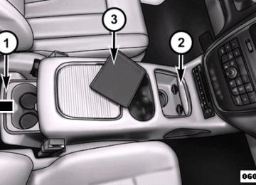
Head Restraints — Third Row The head restraint in the center position can be raised and lowered for tether routing. Refer to “Occupant Restraints” in “Things To Know Before Starting Your Vehicle” for further information. Stow ’n Go姞 Seating — If Equipped On vehicles equipped with Stow ’n Go威 seating, the second and third row seats can be folded into the floor for convenient storage. Second Row Stow ’n Go威 On vehicles equipped with Stow ’n Go威 seats, the seats will fold and tumble in one motion. 1. Move the front seat fully forward. 2. Recline the front seatback fully forward. 3. Raise the armrests on the second row seat.
Push Button
Head Restraints — Second Row Bench To raise the head restraint, pull upward on the head restraint. To lower the head restraint, press the push button, located at the base of the head restraint, and push downward on the head restraint.
192 UNDERSTANDING THE FEATURES OF YOUR VEHICLE NOTE: Seat will not stow in the storage bin unless the armrests are raised. 4. Slide the storage bin locking mechanism to the “LOCK” position and then pull up on the storage bin latch to open the cover.
5. Pull upward on the seatback recliner lever located on
the outboard side of the seat.
Storage Bin Cover Lock Release
Seatback Recliner Lever, Seat Tumble,
And Head Restraint Fold Lever
The non-adjustable head restraint and seatback will fold automatically during the seat tumble. No additional actuation is necessary.
UNDERSTANDING THE FEATURES OF YOUR VEHICLE 193
Non-Adjustable Head Restraint
Automatic Folding Seatback
194 UNDERSTANDING THE FEATURES OF YOUR VEHICLE The seat will automatically tumble into position for easy storage.
Tumbled Second Row Seat
6. Push the seat into the storage bin.
7. Close the storage bin cover.
Seat In Storage Bin
CAUTION!
The storage bin cover must be locked and flat to avoid damage from contact with the front seat tracks, which have minimal clearance to the cover.
WARNING!
In a collision, serious injury could result if the seat storage bin covers are not properly latched. • Do not drive the vehicle with the storage bin covers open. • Keep the storage bin covers closed and latched while the vehicle is in motion. • Do not use a storage bin latch as a tie down.
UNDERSTANDING THE FEATURES OF YOUR VEHICLE 195
To Unstow Second Row Seats 1. Pull up on the storage bin latch to open the cover. 2. Pull up on the strap to lift the seat out of the storage bin and push the seat rearward to latch the seat anchors.
3. Lift the seatback to the full upright position. 4. Return the head restraint to its upright position, close the storage bin cover and slide the storage bin locking mechanism to the “Unlocked” position.
Stow ’n Go威 Seat — Folded And Latched Position To tumble or stow the seat from the folded and latched position: return the seatback and head restraint to the upright position. Then pull up on the seatback recliner lever on the outboard side of the seat to fold head rest and seatback and tumble seat forward.
196 UNDERSTANDING THE FEATURES OF YOUR VEHICLE 1. Return the seatback to the upright position.
Raising The Seatback
2. Return the head restraint to the upright position.
Raising The Head Restraint
3. Pull up on the seatback recliner lever on the outboard side of the seat to fold head rest and seatback and tumble seat forward.
Easy Entry Second Row The second row Stow ’n Go威 seats allow easy entry to the third row seat or rear cargo area. Pull up on the seatback recliner lever on the outboard side of the seat.
UNDERSTANDING THE FEATURES OF YOUR VEHICLE 197
The seat will automatically fold into position for easy entry into the third row.WARNING!
In the event of a collision you could be injured if the seat is not fully latched.
Seatback Recliner Lever, Seat Tumble,
And Head Restraint Fold Lever
198 UNDERSTANDING THE FEATURES OF YOUR VEHICLE Quad Seats — If Equipped Both Quad seats are adjustable forward or rearward. The manual seat adjustment handle is located under the seat cushion at the front edge of each seat.
Manual Seat Adjuster
While sitting in the seat, pull up on the handle and slide the seat forward or rearward. Release the bar once you have reached the desired position. Then, using body pressure, move forward and rearward on the seat to be sure that the seat adjusters have latched.
WARNING!
• Adjusting a seat while driving may be dangerous. Moving a seat while driving could result in loss of control which could cause a collision and serious injury or death. • Seats should be adjusted before fastening the seat belts and while the vehicle is parked. Serious injury or death could result from a poorly adjusted seat belt.
Manual Recline To recline, lean forward slightly, lift the lever, then push back to the desired position and release the lever. Lean forward and lift the lever to return the seatback to its normal position. Using body pressure, lean forward and rearward on the seat to be sure the seatback has latched.
UNDERSTANDING THE FEATURES OF YOUR VEHICLE 199
WARNING!
Do not ride with the seatback reclined so that the shoulder belt is no longer resting against your chest. In a collision you could slide under the seat belt, which could result in serious injury or death.
Recline Lever
200 UNDERSTANDING THE FEATURES OF YOUR VEHICLE Fold-Flat To fold the seat, lift the recliner lever to the full upward position and push the seatback forward until it rests on the seat cushion.
Easy Entry The Quad seats can be tilted forward for easy entry into the third row. With the Quad seat in the fold-flat position, lift up on the easy entry lever located near the bottom of the seat and lift the seat forward.
Fold-Flat Quad Seat
Easy Entry Lever
For passengers seated in the third row, there is a pull strap located on the outboard side of the seat near the bottom of the seat back. Third row passengers can pull on the strap and push the Quad seat forward for folding the seatback and accessing the easy entry lever.
UNDERSTANDING THE FEATURES OF YOUR VEHICLE 201
Removal The Quad seats can be removed if additional storage is needed. With the seat in the easy entry position, lift the cross beam forward and up to release the front anchor latches.
Pull Strap for Third Row Passengers
Cross Beam For Seat Removal
202 UNDERSTANDING THE FEATURES OF YOUR VEHICLE Second Row Bench Seat — If Equipped While the bench seat does not stow in the floor, it is removable for added cargo space.
indicator button pops up when the seat is unlocked. The seat assembly can now be removed from the vehicle and moved on its Easy Out威 Rollers.
Second Row Bench Seat
Release levers are located on the rear leg assemblies, near the floor. To remove the seat, squeeze each release handle and rotate downwards to deploy the wheels. A lock
Release Handles
To reinstall the seat, align the seat into the detent posi- tions on the floor. Squeeze the release handle and rotate upward until the lock indicator button returns into the handle.
WARNING!
If not properly latched, the bench seats could become loose. Personal injuries could result. After reinstall- ing these seats, be sure the red indicator button on the release handles return into the handles.
Third Row Power Recline — If Equipped The power recline feature, located on the side of the seat cushion, adjusts the seatback angle forward/rearward for occupant comfort.
UNDERSTANDING THE FEATURES OF YOUR VEHICLE 203
Third Row Power Seat Switch
Third Row Power Folding Seat — If Equipped A one-touch power folding seat switch is located in the left rear trim panel as part of a switch bank.
204 UNDERSTANDING THE FEATURES OF YOUR VEHICLE NOTE: Lower the head restraint by pulling on the release strap marked “1” located on the outboard side of the head restraint.
Head Restraint Release Strap “1”
The switch is only functional when the liftgate is open and the vehicle is in PARK.
One Touch Folding Seat Third Row
The rear switch bank allows multiple power folding and unfolding positions for the third row seats.
Left and right third row seats can be folded individually or together. The third row power folding seat adjusts to the following positions using the switch bank located on the left rear trim panel:
Rear Panel Power Switch Bank
1 — Open to Normal 3 — Tailgate/Fold Flat
2 — Stow 4 — Right/Left Seats/Both Seats
UNDERSTANDING THE FEATURES OF YOUR VEHICLE 205
NOTE: • Disconnect the center shoulder belt from the small buckle and lower the head restraints before attempting to fold/stow the power third row seats. • To abort seat operation while seat is in motion, press a different seat position selector switch to stop the seat. Once the seat stops moving, then the desired position can be selected. • The third row power seat system includes obstacle detection for safe operation. When the system detects an obstacle, the motors will stop and reverse the motion a short distance to move the seat away from the obstacle. Should this occur, remove the obstacle and press the button again, for the desired position.
206 UNDERSTANDING THE FEATURES OF YOUR VEHICLE Manually Folding Third Row Seats — If Equipped
1. Lower the center head restraint down to the seatback by pushing the button on the guide and pushing the head restraint down.
2. Lower the outboard head restraints by pulling on the release strap marked “1” located on the outboard side of the head restraint.
Head Restraint Release Strap “1”
3. Pull release strap marked “2” located on the rear of the
seat to lower the seatback.
UNDERSTANDING THE FEATURES OF YOUR VEHICLE 207
4. Pull release strap marked “3” to release the anchors.Release Strap “2”
Release Strap “3”
208 UNDERSTANDING THE FEATURES OF YOUR VEHICLE 5. Pull release strap marked “4” and tumble the seat
rearward into the storage bin.
Release Strap “4”
Stowed Third Row Seat
To Unfold Third Row Seats 1. Pull up on the assist strap to lift the seat out of the the
storage bin and push the seat forward until anchors latch.
2. Pull release strap marked “2” to unlock the recliner.
3. Pulling strap “4” releases the seatback to return to its
full upright position.
4. Raise the head restraint to its upright position.
WARNING!
In a collision, you or others in your vehicle could be injured if seats are not properly latched to their floor attachments. Always be sure the seats are fully latched.
Tailgate Mode 1. Pull release strap “3”, then pull release strap “4” to
rotate the entire seat rearward.
2. To restore the seat to its upright position, lift up on the
seatback and push forward until the anchors latch.
UNDERSTANDING THE FEATURES OF YOUR VEHICLE 209
WARNING!
To avoid serious injury or death, never operate the vehicle with occupants in the third row seat while in the tailgate mode.
Plastic Grocery Bag Retainer Hooks Retainer hooks which will hold plastic grocery bag handles are built into the seatbacks of all rear seats and some front seats. The floor supports the partial weight of the bagged goods.
210 UNDERSTANDING THE FEATURES OF YOUR VEHICLE DRIVER MEMORY SEAT — IF EQUIPPED The Memory Buttons 1 and 2 on the driver’s door panel can be programmed to recall the driver’s seat, outside mirrors, adjustable brake and accelerator pedals, and radio station preset settings. Your Remote Keyless Entry (RKE) transmitters can also be programmed to recall the same positions when the UNLOCK button is pressed.
Driver Memory Switch
Your vehicle may have been delivered with two RKE transmitters. Only one RKE transmitter can be linked to each of the memory positions. Setting Memory Positions And Linking RKE Transmitter To Memory
NOTE: Each time the SET (S) button and a numbered button (1 or 2) is pressed, you erase the memory settings for that button and store a new one. 1. Insert the ignition key and turn the ignition switch to
the ON position.
2. Press the driver door MEMORY button number 1 if you are setting the memory for driver 1, or button number 2 if you are setting the memory for driver 2. The system will recall any stored settings. Wait for the system to complete the memory recall before continu- ing to Step 3.
3. Adjust the driver’s seat, recliner, and driver’s side-
view mirror to the desired positions.
4. Adjust the brake and accelerator pedals to the desired
positions.
5. Turn on the radio and set the radio station presets
(up to 10 AM and 10 FM stations can be set).
6. Turn the ignition switch to the OFF position and
remove the key.
7. Press and release the SET (S) button located on the
driver’s door.
8. Within five seconds, press and release MEMORY button 1 or 2 on the driver’s door. The next step must be performed within 5 seconds if you desire to also use a RKE transmitter to recall memory positions.
9. Press and release the LOCK button on one of the RKE
transmitters.
UNDERSTANDING THE FEATURES OF YOUR VEHICLE 211
10. Insert the ignition key and turn the ignition switch tothe ON position.
11. Select “Remote Linked to Memory” in the Electronic Vehicle Information Center (EVIC) and enter “Yes”. Refer to “Electronic Vehicle Information Center (EVIC)/Customer-Programmable Features” in “Un- derstanding Your Instrument Panel” for further in- formation.
12. Repeat the above steps to set the next Memory position using the other numbered Memory button or to link another RKE transmitter to memory.
Memory Position Recall NOTE: The vehicle must be in PARK to recall memory positions. If a recall is attempted when the vehicle is not in PARK, a message will be displayed in the EVIC.
212 UNDERSTANDING THE FEATURES OF YOUR VEHICLE To recall the memory settings for driver one, press MEMORY button 1 on the driver’s door or the UNLOCK button on the RKE transmitter linked to memory posi- tion 1. To recall the memory setting for driver two, press MEMORY button 2 on the driver’s door or the UNLOCK button on the RKE transmitter linked to Memory Posi- tion 2. A recall can be cancelled by pressing any of the MEMORY buttons on the driver’s door during a recall (S, 1, or 2). When a recall is cancelled, the driver’s seat, driver’s mirror, and the pedals stop moving. A delay of one second will occur before another recall can be selected. To Disable RKE Transmitter Linked To Memory 1. Turn the ignition switch to the OFF position and
remove the key.
2. Press and release MEMORY button 1. The system will recall any memory settings stored in position 1. Wait for the system to complete the memory recall before continuing to Step 3.
3. Press and release the memory SET (S) button located on the driver’s door. A chime will sound signaling that you are in the memory set mode.
4. Within five seconds, press and release MEMORY button 1 on the driver’s door. A chime will sound signaling to you that the driver memory has been set. 5. Within five seconds, press and release the UNLOCK button on the RKE transmitter. A chime will sound signaling to you that the RKE transmitter link has been successfully disabled.
To disable another RKE transmitter linked to either Memory Position, repeat Steps 1 to 5 for each RKE transmitter.
NOTE: Once programmed, all RKE transmitters linked to memory can be easily enabled or disabled at one time. Refer to “Electronic Vehicle Information Center (EVIC)/ Customer-Programmable Features⬙ in “Understanding Your Instrument Panel” for further information. Easy Entry/Exit Seat (Available With Memory Seat ONLY) This feature provides automatic driver seat positioning to enhance driver mobility when entering and exiting the vehicle. The distance the driver seat moves depends on where you have the driver seat positioned when you remove the key from the ignition switch. • When you remove the key from the ignition switch, the driver seat will move about 2.4 in (60 mm) rear- ward if the driver seat position is greater than or equal
UNDERSTANDING THE FEATURES OF YOUR VEHICLE 213
to 2.7 in (67.7 mm) forward of the rear stop. The seat will return to its previously set position when you insert the key into the ignition switch and turn it out of the LOCK position. • When you remove the key from the ignition switch the driver seat will move to a position 0.3 in (7.7 mm) forward of the rear stop if the driver seat position is between 0.9 – 2.7 in (22.7 – 67.7 mm) forward of the rear stop. The seat will return to its previously set position when you insert the key into the ignition switch and turn it out of the LOCK position. • The Easy Entry/Easy Exit feature is disabled when the driver seat position is less than 0.9 in (22.7 mm) forward of the rear stop. At this position, there is no benefit to the driver by moving the seat for Easy Exit or Easy Entry.214 UNDERSTANDING THE FEATURES OF YOUR VEHICLE Each stored memory setting will have an associated Easy Entry and Easy Exit Position. NOTE: The Easy Entry/Easy Exit feature can be enabled or disabled through the programmable features in the Electronic Vehicle Information Center (EVIC). If your vehicle is not equipped with an EVIC, your dealership can activate/deactivate this feature for you. For details, refer to “Electronic Vehicle Information Center (EVIC)/ Customer-Programmable Features” in “Understanding Your Instrument Panel” for further information.
TO OPEN AND CLOSE THE HOOD To open the hood, two latches must be released. 1. Pull the hood release lever located on the instrument
panel, below the steering column.
Hood Release Lever
2. Move to the front of the vehicle and look inside the center of the hood opening. Locate, then push the safety catch downward while raising the hood at the same time.
UNDERSTANDING THE FEATURES OF YOUR VEHICLE 215
Use the hood prop rod to secure the hood in the open position.Safety Lever Location
Hood Prop Rod
LIGHTS Headlight Switch The headlight switch is located on the left side of the instrument panel. The switch controls the operation of the headlights, parking lights, instrument panel lights, interior lights and the fog lights.
216 UNDERSTANDING THE FEATURES OF YOUR VEHICLE
CAUTION!
To prevent possible damage, do not slam the hood to close it. Lower the hood until it is open approxi- mately 12 in (30 cm) and then drop it. This should secure both latches. Never drive your vehicle unless the hood is fully closed, with both latches engaged.
WARNING!
Be sure the hood is fully latched before driving your vehicle. If the hood is not fully latched, it could open when the vehicle is in motion and block your vision. Failure to follow this warning could result in serious injury or death.
Headlight Switch With Halo Control
Rotate the headlight switch clockwise to the first detent for parking light and instrument panel light operation. Rotate the headlight switch to the second detent for headlight, parking light and instrument panel operation. Automatic Headlights — If Equipped This system automatically turns your headlights on or off based on ambient light levels. To turn the system on, turn the headlight switch to the extreme counterclockwise position aligning the indicator with the AUTO on the headlight switch. When the system is on, the Headlight Time Delay feature is also on. This means your headlights will stay on for up to 90 seconds after you turn the ignition switch OFF. To turn the Automatic System off, turn the headlight switch clockwise to the O (OFF) position. NOTE: The engine must be running before the head- lights will come on in the Automatic mode.
UNDERSTANDING THE FEATURES OF YOUR VEHICLE 217
Headlights On With Wipers — If Equipped When your headlights are in the AUTO mode and the engine is running, the headlights will automatically turn on when the wiper system is also turned on. Headlights on when windshield wipers are on may be found on vehicles equipped with an automatic headlight system. Refer to “Electronic Vehicle Information Center (EVIC)/ Customer-Programmable Features” in “Understanding Your Instrument Panel” for further information. Headlight Delay — If Equipped This feature provides the safety of headlight illumination for up to 90 seconds after exiting your vehicle. To activate the delay feature, turn OFF the ignition switch while the headlights are still on. Then turn off the headlights within 45 seconds. The 90 second delay inter- val begins when headlight switch is turned off. If the headlights or parking lights are turned back on or the ignition switch is turned ON, the delay will be cancelled.
218 UNDERSTANDING THE FEATURES OF YOUR VEHICLE When exiting the vehicle the driver can choose to have the headlights remain on for 30, 60 or 90 seconds or not remain on. To change the timer setting, see your autho- rized dealer. The headlight delay time is programmable on vehicles equipped with an EVIC. Refer to “Electronic Vehicle Information Center (EVIC)/Customer-Programmable Features” in “Understanding Your Instrument Panel” for further information. If the headlights are turned off before the ignition, they will turn off in the normal manner. NOTE: The headlights must be turned off within 45 seconds of turning the ignition OFF to activate this feature.
Lights-On Reminder If the headlights or the parking lights are left on, or if the dimmer control is in the extreme top position after the ignition switch is turned OFF, a chime will sound when the driver’s door is opened. Daytime Running Lights — If Equipped The headlights on your vehicle will illuminate when the engine is started and the transmission is in any gear except PARK. This provides a constant lights on condi- tion until the ignition is turned OFF. The lights illuminate at less than 50% of normal intensity. If the parking brake is applied, the Daytime Running Lights (DRL) will turn off. Also, if a turn signal is activated, the DRL lamp on the same side of the vehicle will turn off for the duration of the turn signal activation. Once the turn signal is no longer active, the DRL lamp will illuminate.
Front Fog Lights — If Equipped
To activate the front fog lights, turn on the parking lights or the low beam headlights and push in the headlight switch control knob. Pressing the headlight switch control knob in a second time will turn the front fog lights off. Dimmer Controls The dimmer switch is located next to the headlight switch.
UNDERSTANDING THE FEATURES OF YOUR VEHICLE 219
Dimmer Control
With the parking lights or headlights on, rotating the dimmer control upward will increase the brightness of the instrument panel lights.
220 UNDERSTANDING THE FEATURES OF YOUR VEHICLE Interior Lighting On Rotate the left dimmer control completely upward to the second detent (extreme top position) to turn on the interior lights. The interior lights will remain on when the dimmer control is in this position. Interior lights are also turned on when a door or liftgate is opened, the Remote Keyless Entry (RKE) transmitter is activated, or when the dimmer control is moved to the extreme top. The interior lights will automatically turn off in approxi- mately 10 minutes for the first activation and 90 seconds every activation thereafter until the engine is started, if one of the following occur: • A door, sliding door or the liftgate is left open • Any overhead reading light is left on
NOTE: The key must be out of the ignition switch or the ignition switch must be in the OFF position for this feature to operate. Interior Lighting Off Rotate the left dimmer control to the off position (extreme bottom). The interior lights will remain off when the doors or liftgate are open. Parade Mode (Daytime Brightness Feature) Rotate the left dimmer control to the first detent. This feature brightens the odometer, radio and overhead displays when the parking lights or headlights are on. Halo Lights — If Equipped Halo lights are strategically placed soft lighting that help to illuminate specific areas to aid the occupants in locating specific features while driving at night.
The Halo control switch is located to the right of the dimmer switch.
UNDERSTANDING THE FEATURES OF YOUR VEHICLE 221
Multifunction Lever The multifunction lever is located on the left side of the steering column.
Halo Control
To activate the Halo lights, rotate the Halo switch control upward or downward to in- crease or decrease the lighting.
Multifunction Lever
222 UNDERSTANDING THE FEATURES OF YOUR VEHICLE The multifunction lever controls the: • Turn Signals • Headlight Beams Low/High • Flash-To-Pass (Optical Horn) • Front and Rear Wipers — Washer Functions Turn Signals Move the multifunction lever up or down and the arrows on each side of the instrument cluster flash to show proper operation of the front and rear turn signal lights. NOTE: If either light remains on and does not flash, or there is a very fast flash rate, check for a defective outside light bulb. If an indicator fails to light when the lever is moved, the indicator bulb is defective.
it would suggest
that
Turn Signal Warning If the vehicle electronics sense that the vehicle has traveled at over 18 mph (29 km/h) for about 1 mile (1.6 km) with the turn signals on, a chime will sound to alert the driver. Lane Change Assist Tap the lever up or down once, without moving beyond the detent, and the turn signal (right or left) will flash three times then automatically turn off. High/Low Beam Switch When the headlights are turned on, pushing the multi- function lever toward the instrument panel will switch from low beams to high beams. Pulling back to the neutral position returns the headlights to the low beam operation.
Flash-To-Pass You can signal another vehicle with your headlights by lightly pulling the multifunction lever toward you. This will cause the headlights to turn on at high beam and remain on until the lever is released. Battery Protection This feature provides battery protection to avoid wearing down the battery if the headlights, parking lights, or front fog lights are left on for extended periods of time when the ignition switch is in the LOCK position. After eight minutes of the ignition switch being in the LOCK position and the headlight switch in any position other than OFF or AUTO, the lights will turn off automatically until the next cycle of the ignition switch or headlight switch. The battery protection feature will be disabled if the ignition switch is turned to any other position other than LOCK during the eight minute delay.
UNDERSTANDING THE FEATURES OF YOUR VEHICLE 223
WINDSHIELD WIPER AND WASHERS The wipers and washers are operated by a switch within the multifunction lever. Rotate the end of the multifunc- tion lever to select the desired wiper speed.
Washer And Wiper Controls
224 UNDERSTANDING THE FEATURES OF YOUR VEHICLE NOTE: Always remove any buildup of snow that pre- vents the windshield wiper blades from returning to the off position. If the windshield wiper switch is turned off and the blades cannot return to the off position, damage to the wiper motor may occur.
WARNING!
Sudden loss of visibility through the windshield could lead to a collision. You might not see other vehicles or other obstacles. To avoid sudden icing of the windshield during freezing weather, warm the windshield with the defroster before and during windshield washer use.
Intermittent Wiper System Use the intermittent wiper when weather conditions make a single wiping cycle with a variable pause be- tween cycles desirable. Rotate the end of the multifunc- tion lever to the first detent position, and then turn the end of the lever to select the desired delay interval. There are five delay settings, which allow you to regulate the wipe interval from a minimum of one cycle every second to a maximum of approximately 18 seconds between cycles. The delay intervals will double in duration when the vehicle speed is 10 mph (16 km/h) or less. Windshield Wiper Operation Rotate the end of the lever upward, to the first detent past the intermittent settings for low-speed wiper operation. Rotate the end of the lever upward to the second detent past the intermittent settings for high-speed wiper opera- tion.
Windshield Washers To use the Washer, push on the end of the lever to the second detent and hold while spray is desired. If the lever is pushed while on the intermittent setting, the wipers will turn on and operate for several wipe cycles after the lever is released, and then resume the intermittent inter- val previously selected. If the lever is pushed while the wipers are in the off position, the wipers will operate several wipe cycles, then turn off. Mist Feature Press the end of the multifunction lever inward (toward the steering column) to the first detent and release for a single wiping cycle. NOTE: The mist feature does not activate the washer pump; therefore, no washer fluid will be sprayed on the windshield. The wash function must be used in order to spray the windshield with washer fluid.
UNDERSTANDING THE FEATURES OF YOUR VEHICLE 225
Rear Wiper And Washer Rotating the rotary ring to the first detent activates the rear intermittent wipers. To activate the washers, rotate the rotary ring fully forward and the washers will spray until the ring is released, and then resume the intermit- tent interval. NOTE: Rear window wipers function in the intermittent wiper speed only. Rain Sensing Wipers — If Equipped This feature senses moisture on the windshield and automatically activates the wipers for the driver. This feature is especially useful for road splash or overspray from the windshield washers of the vehicle ahead. Rotate the end of the multifunction lever to one of the five intermittent wiper sensitivity settings to activate this feature.
226 UNDERSTANDING THE FEATURES OF YOUR VEHICLE The sensitivity of the system is adjustable from the multifunction lever. Wiper sensitivity position 3 has been calibrated for best overall wiping sensitivity. If the opera- tor desires more wiping sensitivity, they may select sensitivity positions 4 or 5. If the operator desires less wiping sensitivity, they may select sensitivity positions 2
or 1. Place the multifunction lever in the OFF position when not using the system. NOTE: • The Rain Sensing feature will not operate when the • The Rain Sensing feature may not function properly is present on the • Use of Rain-X威 or products containing wax or siliconewhen ice or dried saltwater windshield.
wiper speed is in the low or high position.
may reduce rain sensor performance.
• The Rain Sensing feature can be turned on and off through the EVIC (if equipped). Refer to “Electronic Vehicle Information Center (EVIC)/Personal Settings (Customer-Programmable Features)” in “Understand- ing Your Instrument Panel” for further information.
The Rain Sensing system has protective features for the wiper blades and arms. It will not operate under the following conditions: • Low Temperature Wipe Inhibit — The Rain Sensing feature will not operate when the ignition is first switched ON, and the vehicle is stationary, and the outside temperature is below 32°F (0°C), unless the wiper control on the multifunction lever is moved, or the vehicle speed becomes greater than 0 mph (0 km/h), or the outside temperature rises above freezing.
UNDERSTANDING THE FEATURES OF YOUR VEHICLE 227
TILT/TELESCOPING STEERING COLUMN This feature allows you to tilt the steering column upward or downward. It also allows you to lengthen or shorten the steering column. The tilt/telescoping lever is located below the steering wheel at the end of the steering column.
• Neutral Wipe Inhibit — The Rain Sensing feature will not operate when the ignition is ON, and the transmis- sion shift lever is in the NEUTRAL position, and the vehicle speed is less than 5 mph (8 km/h), unless the wiper control on the multifunction lever is moved or the shift lever is moved out of the NEUTRAL position. • Remote Start Mode Inhibit — On vehicles equipped with Remote Starting system, Rain Sensing wipers are not operational when the vehicle is in the remote start mode. Once the operator is in the vehicle and has placed the ignition switch in the RUN position, rain sensing wiper operation can resume, if it has been selected, and no other inhibit conditions (mentioned previously) exist.
Tilt/Telescoping Lever
228 UNDERSTANDING THE FEATURES OF YOUR VEHICLE To unlock the steering column, push the lever downward (toward the floor). To tilt the steering column, move the steering wheel upward or downward as desired. To lengthen or shorten the steering column, pull the steering wheel outward or push it inward as desired. To lock the steering column in position, push the lever upward until fully engaged.
WARNING!
Do not adjust the steering column while driving. Adjusting the steering column while driving or driv- ing with the steering column unlocked, could cause the driver to lose control of the vehicle. Failure to follow this warning may result in serious injury or death.
HEATED STEERING WHEEL — IF EQUIPPED The steering wheel contains a heating element that helps warm your hands in cold weather. The heated steering wheel has only one temperature setting. Once the heated steering wheel has been turned on it will operate for approximately 58 to 70 minutes before automatically shutting off. The heated steering wheel can shut off early or may not turn on when the steering wheel is already warm. The heated steering wheel switch is located on the switch bank below the climate controls.
Press the switch to turn on the heated steering wheel. The light on the switch will illuminate to indicate the steering wheel heater is on. Pressing the switch a second time will turn off the heated steering wheel and light indicator.
NOTE: The engine must be running for the heated steering wheel to operate. Vehicles Equipped With Remote Start On models that are equipped with remote start, the heated steering wheel can be programmed to come on during a remote start. Refer to “Remote Starting Sys- tem — If Equipped” in “Things to Know Before Starting Your Vehicle” for further information.
WARNING!
• Persons who are unable to feel pain to the skin because of advanced age, chronic illness, diabetes, spinal cord injury, medication, alcohol use, exhaus- tion, or other physical conditions must exercise care when using the steering wheel heater. It may cause burns even at low temperatures, especially if used for long periods.
(Continued)
UNDERSTANDING THE FEATURES OF YOUR VEHICLE 229
WARNING! (Continued)
• Do not place anything on the steering wheel that insulates against heat, such as a blanket or steering wheel covers of any type and material. This may cause the steering wheel heater to overheat.
ADJUSTABLE PEDALS — IF EQUIPPED The adjustable pedals system is designed to allow a greater range of driver comfort for steering wheel tilt and seat position. This feature allows the brake, accelerator, and clutch pedals (if equipped) to move toward or away from the driver to provide improved position with the steering wheel.
230 UNDERSTANDING THE FEATURES OF YOUR VEHICLE The switch is located on the left side of the steering column.
Press the switch rearward to move the pedals rearward (toward the driver). • The pedals can be adjusted with the ignition OFF. • The pedals cannot be adjusted when the vehicle is in REVERSE or when the Electronic Speed Control Sys- tem is on. The following messages will be displayed on vehicles equipped with the Electronic Vehicle Informa- tion System (EVIC) if the pedals are attempted to be adjusted when the system is locked out (“Adjustable Pedal Disabled — Cruise Control Engaged” or “Ad- justable Pedal Disabled — Vehicle In Reverse”.
Adjustable Pedal Switch
Press the switch forward to move the pedals forward (toward the front of the vehicle).
NOTE: • Always adjust the pedals to a position that allows full • Further small adjustments may be necessary to find
pedal travel.
the best possible seat/pedal position.
CAUTION!
Do not place any article under the adjustable pedals or impede its ability to move, as it may cause damage to the pedal controls. Pedal travel may become lim- ited if movement is stopped by an obstruction in the adjustable pedal’s path.
WARNING!
Do not adjust the pedals while the vehicle is moving. You could lose control and have an accident. Always adjust the pedals while the vehicle is parked.
ELECTRONIC SPEED CONTROL — IF EQUIPPED When engaged, the Electronic Speed Control takes over accelerator operations at speeds greater than 25 mph (40 km/h).
UNDERSTANDING THE FEATURES OF YOUR VEHICLE 231
The Electronic Speed Control buttons are located on the right side of the steering wheel.Electronic Speed Control Buttons
1 — ON/OFF 4 — CANCEL
2 — RES + 3 — SET -
232 UNDERSTANDING THE FEATURES OF YOUR VEHICLE NOTE: In order to ensure proper operation, the Elec- tronic Speed Control System has been designed to shut down if multiple Speed Control functions are operated at the same time. If this occurs, the Electronic Speed Control System can be reactivated by pushing the Electronic Speed Control ON/OFF button and resetting the desired vehicle set speed. To Activate Push the ON/OFF button. The Cruise Indicator Light in the instrument cluster will illuminate. To turn the system off, push the ON/OFF button a second time. The Cruise Indicator Light will turn off. The system should be turned off when not in use.
WARNING!
Leaving the Electronic Speed Control system on when not in use is dangerous. You could accidentally set the system or cause it to go faster than you want. You could lose control and have an accident. Always leave the system OFF when you are not using it.
To Set A Desired Speed Turn the Electronic Speed Control ON. When the vehicle has reached the desired speed, press the SET (-) button and release. Release the accelerator and the vehicle will operate at the selected speed. NOTE: The vehicle should be traveling at a steady speed and on level ground before pressing the SET button. To Deactivate A soft tap on the brake pedal, pushing the CANCEL button, or normal brake pressure while slowing the
vehicle will deactivate Electronic Speed Control without erasing the set speed memory. Pressing the ON/OFF button or turning the ignition switch OFF erases the set speed memory. To Resume Speed To resume a previously set speed, push the RES (+) button and release. Resume can be used at any speed above 20 mph (32 km/h). To Vary The Speed Setting When the Electronic Speed Control is set, you can in- crease speed by pushing the RES (+) button. If the button is continually pressed, the set speed will continue to increase until the button is released, then the new set speed will be established. Pressing the RES (+) button once will result in a 1 mph (1.6 km/h) increase in set speed. Each subsequent tap of the button results in an increase of 1 mph (1.6 km/h).
UNDERSTANDING THE FEATURES OF YOUR VEHICLE 233
To decrease speed while the Electronic Speed Control is set, push the SET (-) button. If the button is continually held in the SET (-) position, the set speed will continue to decrease until the button is released. Release the button when the desired speed is reached, and the new set speed will be established. Pressing the SET (-) button once will result in a 1 mph (1.6 km/h) decrease in set speed. Each subsequent tap of the button results in a decrease of 1 mph (1.6 km/h). To Accelerate For Passing Press the accelerator as you would normally. When the pedal is released, the vehicle will return to the set speed. Using Electronic Speed Control On Hills The transmission may downshift on hills to maintain the vehicle set speed.234 UNDERSTANDING THE FEATURES OF YOUR VEHICLE NOTE: The Electronic Speed Control system maintains speed up and down hills. A slight speed change on moderate hills is normal. On steep hills, a greater speed loss or gain may occur so it may be preferable to drive without Electronic Speed Control.
WARNING!
Electronic Speed Control can be dangerous where the system cannot maintain a constant speed. Your ve- hicle could go too fast for the conditions, and you could lose control and have an accident. Do not use Electronic Speed Control in heavy traffic or on roads that are winding, icy, snow-covered or slippery.
PARKSENSE姞 REAR PARK ASSIST — IF EQUIPPED The ParkSense威 Rear Park Assist system provides visual and audible indications of the distance between the rear fascia and a detected obstacle when backing up, e.g. during a parking maneuver. Refer to ParkSense威 System Usage Precautions for limitations of this system and recommendations. ParkSense威 will retain the last system state (enabled or disabled) from the last ignition cycle when the ignition is changed to the ON/RUN position. ParkSense威 can be active only when the shift lever is in REVERSE. If ParkSense威 is enabled at this shift lever position, the system will remain active until the vehicle speed is increased to approximately 11 mph (18 km/h) or above. The system will become active again if the vehicle speed is decreased to speeds less than approximately 10 mph (16 km/h).
ParkSense姞 Sensors The four ParkSense威 sensors, located in the rear fascia/ bumper, monitor the area behind the vehicle that is within the sensors’ field of view. The sensors can detect obstacles from approximately 12 in (30 cm) up to 79 in (200 cm) from the rear fascia/bumper in the horizontal direction, depending on the location, type and orienta- tion of the obstacle. ParkSense姞 Warning Display The ParkSense威 Warning screen will only be displayed if Sound and Display is selected from the Customer- Pro- grammable Features section of the Electronic Vehicle Information Center (EVIC). Refer to “Electronic Vehicle Information Center (EVIC)/Personal Settings (Customer- Programmable Features)” in “Understanding Your In- strument Panel” for further information.
UNDERSTANDING THE FEATURES OF YOUR VEHICLE 235
The ParkSense威 Warning Display is located in the Instru- ment cluster’s EVIC display. It provides both visual and audible warnings to indicate the distance between the rear fascia/bumper and the detected obstacle.ParkSense威 Warning Display
236 UNDERSTANDING THE FEATURES OF YOUR VEHICLE ParkSense姞 Display When the vehicle is in REVERSE, the warning display will turn ON indicating the system status.
Park Assist System OFF
Park Assist System ON
The system will indicate a detected obstacle by showing three solid arcs and will produce a one-half second tone. As the vehicle moves closer to the object the EVIC display will show fewer arcs and the sound tone will change from slow, to fast, to continuous.
UNDERSTANDING THE FEATURES OF YOUR VEHICLE 237
Fast Tone
Slow Tone
238 UNDERSTANDING THE FEATURES OF YOUR VEHICLE
The vehicle is close to the obstacle when the EVIC display shows one flashing arc and sounds a continuous tone. The following chart shows the warning alert operation when the system is detecting an obstacle:
Continuous Tone
UNDERSTANDING THE FEATURES OF YOUR VEHICLE 239
Rear Distance
(in/cm)
Greater than 79 in (200 cm)
Audible Alert