- 2012 Dodge Challenger Owners Manuals
- Dodge Challenger Owners Manuals
- 2009 Dodge Challenger Owners Manuals
- Dodge Challenger Owners Manuals
- 2010 Dodge Challenger Owners Manuals
- Dodge Challenger Owners Manuals
- 2013 Dodge Challenger Owners Manuals
- Dodge Challenger Owners Manuals
- 2011 Dodge Challenger Owners Manuals
- Dodge Challenger Owners Manuals
- Download PDF Manual
-
chances of successfully making a phone call as to that for the mobile phone directly.
some systems. To do this, press the say “Setup”, followed by “Emergency”.
WARNING!
To use your Uconnect™ Phone System in an emer- gency, your mobile phone must be: • turned on, • paired to the Uconnect™ System, • and have network coverage.
UNDERSTANDING THE FEATURES OF YOUR VEHICLE 107
Towing Assistance If you need towing assistance: • Press the • After the “Ready” prompt and the following beep, say
button to begin.
“Towing Assistance”.
NOTE: • The towing assistance number dialed is based on the country where the vehicle is purchased (1-800-528- 2069 for the U.S., 1-877-213-4525 for Canada, 55-14- 3454 for Mexico City and 1-800-712-3040 for outside Mexico City in Mexico). Please refer to the 24-Hour “Towing Assistance” coverage details on the DVD in the Warranty Information Booklet and the 24-Hour Towing Assistance references. • If supported, this number may be programmable on button and
some systems. To do this, press the say “Setup”, followed by “Towing Assistance”.
108 UNDERSTANDING THE FEATURES OF YOUR VEHICLE Paging To learn how to page, refer to “Working with Automated Systems”. Paging works properly except for pagers of certain companies, which time out a little too soon to work properly with the Uconnect™ Phone. Voice Mail Calling To learn how to access your voice mail, refer to “Working with Automated Systems”. Working With Automated Systems This method is used in instances where one generally has to press numbers on the mobile phone keypad while navigating through an automated telephone system. You can use your Uconnect™ Phone to access a voice mail system or an automated service, such as a paging service or automated customer service line. Some ser- vices require immediate response selection. In some instances, the Uconnect™ Phone.
that may be too quick for use of
When calling a number with your Uconnect™ Phone that normally requires you to enter in a touch-tone sequence on your mobile phone keypad, you can press the button and say the sequence you wish to enter, followed by the word “Send”. For example, if required to enter your PIN followed with a pound, (3 7 4 6 #), you can button and say, “3 7 4 6 #Send”. Saying press the a number, or sequence of numbers, followed by “Send”, is also to be used for navigating through an automated customer service center menu structure, and to leave a number on a pager. You can also send stored Uconnect™ phonebook entries as tones for fast and easy access to voice mail and pager entries. To use this feature, dial the number you wish to button and say, “Send.” The call and then press the system will prompt you to enter the name or number and say the name of the phonebook entry you wish to send.
The Uconnect™ Phone will then send the corresponding phone number associated with the phonebook entry, as tones over the phone. NOTE: • You may not hear all of the tones due to mobile phone • Some paging and voice mail systems have system time out settings that are too short and may not allow the use of this feature.
network configurations. This is normal.
Barge In — Overriding Prompts The “Voice Command” button can be used when you wish to skip part of a prompt and issue your voice command immediately. For example, if a prompt is asking “Would you like to pair a phone, clear a...,” you button and say, “Pair a Phone” to could press the select that option without having to listen to the rest of the voice prompt.
UNDERSTANDING THE FEATURES OF YOUR VEHICLE 109
Turning Confirmation Prompts ON/OFF Turning confirmation prompts off will stop the system from confirming your choices (e.g., the Uconnect™ Phone will not repeat a phone number before you dial it). • Press the • After the “Ready” prompt and the following beep, say
button to begin.
one of the following: − “Setup Confirmation Prompts On” − “Setup Confirmation Prompts Off”
Phone And Network Status Indicators If available on the radio and/or on a premium display such as the instrument panel cluster, and supported by your mobile phone, the Uconnect™ Phone will provide notification to inform you of your phone and network status when you are attempting to make a phone call using Uconnect™ Phone. The status is given for network signal strength, phone battery strength, etc.
110 UNDERSTANDING THE FEATURES OF YOUR VEHICLE Dialing Using The Mobile Phone Keypad You can dial a phone number with your mobile phone keypad and still use the Uconnect™ Phone (while dialing via the mobile phone keypad, the user must exercise caution and take precautionary safety measures). By dialing a number with your paired Bluetooth威 mobile phone, the audio will be played through your vehicle’s audio system. The Uconnect™ Phone will work the same as if you dial the number using Voice Command. NOTE: Certain brands of mobile phones do not send the dial ring to the Uconnect™ Phone to play it on the vehicle audio system, so you will not hear it. Under this situa- tion, after successfully dialing a number the user may feel that the call did not go through even though the call is in progress. Once your call is answered, you will hear the audio.
Mute/Un-Mute (Mute OFF) When you mute the Uconnect™ Phone, you will still be able to hear the conversation coming from the other party, but the other party will not be able to hear you. In order to mute the Uconnect™ Phone: • Press the • Following the beep, say “Mute”. In order to un-mute the Uconnect™ Phone: • Press the • Following the beep, say “Mute off”. Advanced Phone Connectivity
button.
button.
Transfer Call To And From Mobile Phone The Uconnect™ Phone allows ongoing calls to be trans- ferred from your mobile phone to the Uconnect™ Phone without terminating the call. To transfer an ongoing call
from your Uconnect™ Phone paired mobile phone to the button Uconnect™ Phone or vice versa, press the and say “Transfer Call”. Connect Or Disconnect Link Between The Uconnect™ Phone And Mobile Phone Your mobile phone can be paired with many different electronic devices, but can only be actively “connected” with one electronic device at a time. If you would like to connect or disconnect the Bluetooth威 connection between your mobile phone and the Uconnect™ Phone System, follow the instructions de- scribed in your mobile phone User’s Manual. List Paired Mobile Phone Names • Press the • After the “Ready” prompt and the following beep, say
button to begin.
“Setup Phone Pairing”.
UNDERSTANDING THE FEATURES OF YOUR VEHICLE 111
• When prompted, say “List Phones”. • The Uconnect™ Phone will play the phone names of all paired mobile phones in order from the highest to the lowest priority. To “Select” or “Delete” a paired button and phone being announced, press the say “Select” or “Delete”. Also, see the next two sec- tions for an alternate way to “Select” or “Delete” a paired phone.
button to begin.
Select Another Mobile Phone This feature allows you to select and start using another phone paired with the Uconnect™ Phone. • Press the • After the “Ready” prompt and the following beep, say • You can also press the
button at any time while the list is being played, and then choose the phone that you wish to select.
“Setup Select Phone” and follow the prompts.
112 UNDERSTANDING THE FEATURES OF YOUR VEHICLE
• The selected phone will be used for the next phone call. the Uconnect™ Phone will return to using the highest priority phone present in or near (approximately within 30 ft (9 m)) the vehicle.
the selected phone is not available,
If
button to begin.
“Setup Phone Pairing”.
Delete Uconnect™ Phone Paired Mobile Phones • Press the • After the “Ready” prompt and the following beep, say • At the next prompt, say “Delete” and follow the • You can also press the
button at any time while the list is being played, and then choose the phone you wish to delete.
prompts.
Things You Should Know About Your Uconnect™ Phone
Uconnect™ Phone Tutorial To hear a brief tutorial of the system features, press the
button and say “Uconnect™ Tutorial.”
Voice Training For users experiencing difficulty with the system recog- nizing their voice commands or numbers, the Uconnect™ Phone Voice Training feature may be used. To enter this training mode, follow one of the two following proce- dures: From outside the Uconnect™ Phone mode (e.g., from radio mode): • Press and hold the • Press the
button and say the “Voice Training, System Training, or Start Voice Training” command.
button for five seconds until
the session begins, or,
You can either press the Uconnect™ Phone button to restore the factory setting or repeat the words and phrases when prompted by the Uconnect™ Phone. For best results, the Voice Training session should be com- pleted when the vehicle is parked with the engine running, all windows closed, and the blower fan switched off. This procedure may be repeated with a new user. The system will adapt to the last trained voice only. Reset • press the • After the “Ready” prompt, and the following beep, say
button.
“Setup”, then “Reset”.
This will delete all phone pairing, phone book entries, and other settings in all language modes. The System will prompt you before resetting to factory settings.
UNDERSTANDING THE FEATURES OF YOUR VEHICLE 113
Voice Command • For best performance, adjust the rearview mirror to provide at least 1⁄2 in (1 cm) gap between the overhead console (if equipped) and the mirror.
• Always wait for the beep before speaking. • Speak normally, without pausing, just as you would speak to a person sitting a few feet/meters away from you. • Make sure that no one other than you is speaking during a Voice Command period. • Performance is maximized under: • low-to-medium blower setting, • low-to-medium vehicle speed, • low road noise, • smooth road surface,
114 UNDERSTANDING THE FEATURES OF YOUR VEHICLE
• fully closed windows, • dry weather condition. • Even though the system is designed for users speaking in North American English, French, and Spanish ac- cents, the system may not always work for some. • When navigating through an automated system such as voice mail, or when sending a page, at the end of speaking the digit string, make sure to say “Send”. • Storing names in the phonebook when the vehicle is • It is not recommended to store similar sounding • Phonebook (Downloaded and Uconnect™ Phone Lo- cal) name recognition rate is optimized when the entries are not similar.
names in the Uconnect™ Phonebook.
not in motion is recommended.
be spoken “eight-zero-zero” not “eight hundred”.
• Numbers must be spoken in single digits. “800” must • You can say “O” (letter “O”) for “0” (zero). • Even though international dialing for most number combinations is supported, some shortcut dialing number combinations may not be supported. • In a convertible vehicle, system performance may be
compromised with the convertible top down.
Far End Audio Performance • Audio quality is maximized under: • low-to-medium blower setting, • low-to-medium vehicle speed, • low road noise, • smooth road surface,
• fully closed windows, • dry weather conditions, and • operation from the driver’s seat. • Performance, such as audio clarity, echo, and loudness to a large degree rely on the phone and network, and not the Uconnect™ Phone. • Echo at the phone far end can sometimes be reduced • In a convertible vehicle, system performance may be
by lowering the in-vehicle audio volume.
compromised with the convertible top down.
Recent Calls If your phone supports “Automatic Phonebook Down- load”, Uconnect™ Phone can list your Outgoing, Incom- ing and Missed Calls.
UNDERSTANDING THE FEATURES OF YOUR VEHICLE 115
SMS Uconnect™ Phone can read or send new messages on your phone. Read Messages: If you receive a new text message while your phone is connected to Uconnect™ Phone, an announcement will be made to notify you that you have a new text message. If you wish to hear the new message: • Press the • After the “Ready” prompt and the following beep, say • Uconnect™ Phone will play the new text message for
“SMS Read” or “Read Messages.”
button.
you.
After reading a message, you can “Reply” or “Forward” the message using Uconnect™ Phone.
116 UNDERSTANDING THE FEATURES OF YOUR VEHICLE Send Messages: You can send messages using Uconnect™ Phone. To send a new message: • Press the • After the “Ready” prompt and the following beep, say • You can either say the message you wish to send or say
“SMS Send” or “Send Message.”
button.
“List Messages.” There are 20 preset messages.
button while the
To send a message, press the system is listing the message and say “Send.” Uconnect™ Phone will prompt you to say the name or number of the person you wish to send the message to. List of Preset Messages: 1. Yes 2. No
3. Where are you? 4. I need more direction. 5. L O L 6. Why 7. I love you 8. Call me 9. Call me later 10. Thanks 11. See You in 15 minutes 12. I am on my way 13. I’ll be late 14. Are you there yet? 15. Where are we meeting?
16. Can this wait? 17. Bye for now 18. When can we meet 19. Send number to call 20. Start without me Turn SMS Incoming Announcement ON/OFF Turning the SMS Incoming Announcement OFF will stop the system from announcing the new incoming mes- sages. • Press the • After the “Ready” prompt and the following beep, say “Setup, SMS Incoming Message Announcement,” you will then be given a choice to change it.
button.
UNDERSTANDING THE FEATURES OF YOUR VEHICLE 117
Bluetooth威 Communication Link Mobile phones have been found to lose connection to the Uconnect™ Phone. When this happens, the connection can generally be reestablished by switching the phone off/on. Your mobile phone is recommended to remain in Bluetooth威 ON mode. Power-Up After switching the ignition key from OFF to either the ON or ACC position, or after a language change, you must wait at least fifteen seconds prior to using the system.
118 UNDERSTANDING THE FEATURES OF YOUR VEHICLE
UNDERSTANDING THE FEATURES OF YOUR VEHICLE 119
120 UNDERSTANDING THE FEATURES OF YOUR VEHICLE
Voice Commands
Alternate(s)
Primary zero one two three four five six seven eight nine star (*) plus (+) pound (#) add location all
UNDERSTANDING THE FEATURES OF YOUR VEHICLE 121
Voice Commands
Alternate(s)
Primary call cancel confirmation prompts continue delete dial download edit emergency English erase all Espanol Francais help home
122 UNDERSTANDING THE FEATURES OF YOUR VEHICLE
Voice Commands
Alternate(s)
pairing phone book
Primary language list names list phones mobile mute mute off new entry no other pair a phone phone pairing phonebook previous record again redial
Voice Commands
Alternate(s) return or main menu select
phone settings or phone set up
Primary return to main menu select phone send set up
towing assistance transfer call Uconnect™ Tutorial try again voice training work yes
General Information This device complies with Part 15 of the FCC rules and RSS 210 of Industry Canada. Operation is subject to the following conditions: • Changes or modifications not expressly approved by the party responsible for compliance could void the user’s authority to operate the equipment.
• This device may not cause harmful interference. • This device must accept any interference received, including interference that may cause undesired operation.
VOICE COMMAND — IF EQUIPPED
Voice Command System Operation
This Voice Command system allows you to control your AM, FM radio, satellite radio, disc player, and a memo recorder.
UNDERSTANDING THE FEATURES OF YOUR VEHICLE 123
NOTE: Take care to speak into the Voice Interface System as calmly and normally as possible. The ability of the Voice Interface System to recognize user voice com- mands may be negatively affected by rapid speaking or a raised voice level.WARNING!
Any voice commanded system should be used only in safe driving conditions following local laws. All attention should be kept on the roadway ahead. Failure to do so may result in a collision causing serious injury or death.
button, you When you press the Voice Command will hear a beep. The beep is your signal to give a command. If you do not say a command within a few NOTE: seconds, the system will present you with a list of options.
124 UNDERSTANDING THE FEATURES OF YOUR VEHICLE If you ever wish to interrupt the system while it lists button, listen options, press the Voice Command for the beep, and say your command. button while the Pressing the Voice Command system is speaking is known as “barging in.” The system will be interrupted, and after the beep, you can add or change commands. This will become helpful once you start to learn the options. NOTE: At any time, you can say the words “Cancel”, “Help” or “Main Menu”. These commands are universal and can be used from any menu. All other commands can be used depending upon the active application. When using this system, you should speak clearly and at a normal speaking volume.
The system will best recognize your speech if the win- dows are closed, and the heater/air conditioning fan is set to low. At any point, if the system does not recognize one of your commands, you will be prompted to repeat it. To hear the first available Menu, press the Voice button and say “Help” or “Main Command Menu”. Commands The Voice Command system understands two types of commands. Universal commands are available at all times. Local commands are available if the supported radio mode is active. Changing the Volume 1. Start a dialogue by pressing the Voice Command
button.
2. Say a command (e.g., “Help”). 3. Use the ON/OFF VOLUME rotary knob to adjust the volume to a comfortable level while the Voice Command system is speaking. Please note the volume setting for Voice Command is different than the audio system. Main Menu Start a dialogue by pressing the Voice Command button. You may say “Main Menu” to switch to the main menu. In this mode, you can say the following commands: • “Radio” (to switch to the radio mode) • “Disc” (to switch to the disc mode) • “Memo” (to switch to the memo recorder) • “Setup” (to switch to system setup)
UNDERSTANDING THE FEATURES OF YOUR VEHICLE 125
Radio AM To switch to the AM band, say “AM” or “Radio AM”. In this mode, you may say the following commands: • “Frequency #” (to change the frequency) • “Next Station” (to select the next station) • “Previous Station” (to select the previous station) • “Radio Menu” (to switch to the radio menu) • “Main Menu” (to switch to the main menu) Radio FM To switch to the FM band, say “FM” or “Radio FM”. In this mode, you may say the following commands: • “Frequency #” (to change the frequency) • “Next Station” (to select the next station) • “Previous Station” (to select the previous station)
126 UNDERSTANDING THE FEATURES OF YOUR VEHICLE
• “Menu Radio” (to switch to the radio menu) • “Main Menu” (to switch to the main menu) Satellite Radio To switch to satellite radio mode, say “Sat” or “Satellite Radio”. In this mode, you may say the following com- mands: • “Channel Number” (to change the channel by its • “Next Channel” (to select the next channel) • “Previous Channel” (to select the previous channel) • “List Channel” (to hear a list of available channels) • “Select Name” (to say the name of a channel) • “Menu Radio” (to switch to the radio menu) • “Main Menu” (to switch to the main menu)
spoken number)
Disc To switch to the disc mode, say “Disc”. In this mode, you may say the following commands: • “Track” (#) (to change the track) • “Next Track” (to play the next track) • “Previous Track” (to play the previous track) • “Main Menu” (to switch to the main menu) Memo To switch to the voice recorder mode, say “Memo”. In this mode, you may say the following commands: • “New Memo” (to record a new memo) — During the
recording, you may press the Voice Command button to stop recording. You proceed by saying one of the following commands: − “Save” (to save the memo)
− “Continue” (to continue recording) − “Delete” (to delete the recording) • “Play Memos” (to play previously recorded memos) — During the playback you may press the Voice button to stop playing memos. You Command proceed by saying one of the following commands: − “Repeat” (to repeat a memo) − “Next” (to play the next memo) − “Previous” (to play the previous memo) − “Delete” (to delete a memo) • “Delete All” (to delete all memos) Setup To switch to system setup, you may say on of the following: • “Change to setup”
UNDERSTANDING THE FEATURES OF YOUR VEHICLE 127
• “Switch to system setup” • “Change to setup” • “Main menu setup” or • “Switch to setup” In this mode, you may say the following commands: • “Language English” • “Language French” • “Language Spanish” • “Tutorial” • “Voice Training” NOTE: Keep in mind that you have to press the Voice button first and wait for the beep Command before speaking the “Barge In” commands.
128 UNDERSTANDING THE FEATURES OF YOUR VEHICLE Voice Training For users experiencing difficulty with the system recog- nizing their voice commands or numbers the Uconnect™ Voice “Voice Training” feature may be used. button, say “System 1. Press the Voice Command Setup” and once you are in that menu then say “Voice Training.” This will train your own voice to the system and will improve recognition. 2. Repeat the words and phrases when prompted by Uconnect™ Voice. For best results, the “Voice Training” session should be completed when the vehicle is parked, engine running, all windows closed, and the blower fan switched off. This procedure may be repeated with a new user. The system will adapt to the last trained voice only.
SEATS Seats are a part of the Occupant Restraint System of the vehicle.
WARNING!
• It is dangerous to ride in a cargo area, inside or outside of a vehicle. In a collision, people riding in these areas are more likely to be seriously injured or killed. • Do not allow people to ride in any area of your vehicle that is not equipped with seats and seat belts. In a collision, people riding in these areas are more likely to be seriously injured or killed. • Be sure everyone in your vehicle is in a seat and
using a seat belt properly.
Power Seats The power seat switches are located on the outboard side of the front seat cushions. The power seat switches are used to control the position of the seat.
UNDERSTANDING THE FEATURES OF YOUR VEHICLE 129
Adjusting The Seat Up Or Down The height of the seats can be adjusted up or down. Pull upward or push downward on the seat switch, the seat will move in the direction of the switch. Release the switch when the desired position has been reached. Tilting The Seat Up Or Down The angle of the seat cushion can be adjusted in four directions. Pull upward or push downward on the front or rear of the seat switch; the front or rear of the seat cushion will move in the direction of the switch. Release the switch when the desired position has been reached. Power Lumbar — If Equipped Vehicles equipped with power driver or passenger seats are also equipped with power lumbar. The power lumbar switch is located on the outboard side of the power seat. Push the switch forward to increase the lumbar support.
Power Seat Switch
Adjusting The Seat Forward Or Rearward The seat can be adjusted both forward and rearward. Push the seat switch forward or rearward, the seat will move in the direction of the switch. Release the switch when the desired position has been reached.
130 UNDERSTANDING THE FEATURES OF YOUR VEHICLE Push the switch rearward to decrease the lumbar sup- port. Pushing upward or downward on the switch will raise and lower the position of the support.
Power Lumbar Switch
WARNING!
• Adjusting a seat while driving may be dangerous. Moving a seat while driving could result in loss of control which could cause a collision and serious injury or death. • Seats should be adjusted before fastening the seat belts and while the vehicle is parked. Serious injury or death could result from a poorly adjusted seat belt. • Do not ride with the seatback reclined so that the shoulder belt is no longer resting against your chest. In a collision you could slide under the seat belt, which could result in serious injury or death.
CAUTION!
Do not place any article under a power seat or impede its ability to move as it may cause damage to the seat controls. Seat travel may become limited if movement is stopped by an obstruction in the seat’s path.
Heated Seats The front driver and passenger seats may be equipped with heaters in both the seat cushions and seatbacks. The heaters provide the same average heat level for both the cushion and the seatback. There are two heated seat switches that allow the driver and passenger to operate the seats independently. The controls for each seat are located near the bottom center of the instrument panel.
UNDERSTANDING THE FEATURES OF YOUR VEHICLE 131
You can choose from HIGH, LOW or OFF heat settings. Amber indicator lights in each switch indicate the level of heat in use. Two indicator lights will illuminate for HIGH, one for LOW and none for OFF.Press the switch once to select HIGH-level heating. Press the switch a second time to select LOW-level heating. Press the switch a third time to shut the heating elements OFF.
If HIGH-level heating is selected, the system will auto- matically switch to the LOW-level after a maximum of 60 minutes of continuous operation. At that time, the number of indicators illuminated changes from two to one, indicating the change. Operation on the LOW-level setting also turns OFF automatically after a maximum of 45 minutes. NOTE: Once a heat setting is selected, heat will be felt within two to five minutes.
Manual Front Seatback Recline lift the lever located on the To adjust the seatback, outboard side of the seat, lean back to the desired position and release the lever. To return the seatback, lift the lever, lean forward and release the lever.
132 UNDERSTANDING THE FEATURES OF YOUR VEHICLE
WARNING!
• Persons who are unable to feel pain to the skin because of advanced age, chronic illness, diabetes, spinal cord injury, medication, alcohol use, ex- haustion or other physical condition must exercise care when using the seat heater. It may cause burns even at low temperatures, especially if used for long periods of time. • Do not place anything on the seat that insulates against heat, such as a blanket or cushion. This may cause the seat heater to overheat. Sitting in a seat that has been overheated could cause serious burns due to the increased surface temperature of the seat.
Recline Lever
WARNING!
Do not ride with the seatback reclined so that the shoulder belt is no longer resting against your chest. In a collision you could slide under the seat belt, which could result in serious injury or death.
Passenger Seat Easy Entry On the passenger seat, pull forward on the lever located on the side of the seatback in order to dump the seatback and slide the seat forward. You can also temporarily remove the seat belt from the guide loop on the seat and allow the seat belt to retract out of the way. This allows for easier access to the rear seat. To return the seat to a normal seating position, first return the seatback to its original recline location and then slide the entire seat back to the pre-set lock position.
UNDERSTANDING THE FEATURES OF YOUR VEHICLE 133
Head Restraints
Head restraints are designed to reduce the risk of injury by restricting head movement in the event of a rear impact. Head restraints should be adjusted so that the top of the head restraint is located above the top of your ear.
134 UNDERSTANDING THE FEATURES OF YOUR VEHICLE
WARNING!
The head restraints for all occupants must be prop- erly adjusted prior to operating the vehicle or occu- pying a seat. Head restraints should never be ad- justed while the vehicle is in motion. Driving a vehicle with the head restraints improperly adjusted or removed could cause serious injury or death in the event of a collision.
Active Head Restraints — Front Seats The front driver and passenger seats are equipped with Active Head Restraints (AHR). In the event of a rear impact the AHRs will automatically extend forward minimizing the gap between the back of the occupants head and the AHR. The AHRs will automatically return to their normal position following a rear impact. If the AHRs do not return to their normal position see your authorized dealer immediately.
To raise the head restraint, pull upward on the head restraint. To lower the head restraint, press the push button, located at the base of the head restraint, and push downward on the head restraint.
Push Button
NOTE: The head restraints should only be removed by qualified technicians, for service purposes only. If either of the head restraints require removal, see your autho- rized dealer.
WARNING!
Do not place items over the top of the Active Head Restraint, such as coats, seat covers or portable DVD players. These items may interfere with the operation of the Active Head Restraint in the event of a collision and could result in serious injury or death.
Rear Head Restraints The center rear head restraint has two positions, up or down. When the seat is being occupied the head restraint should raised. When there are no occupants in the center seat position the head restraint can be lowered for maximum visibility for the driver.
UNDERSTANDING THE FEATURES OF YOUR VEHICLE 135
To raise the head restraint, pull upward on the head restraint. To lower the head restraint, press the push button, located at the base of the head restraint, and push downward on the head restraint.Push Button
136 UNDERSTANDING THE FEATURES OF YOUR VEHICLE NOTE: The outboard head restraints are not adjustable. Refer to “Occupant Restraints” in “Things To Know Before Starting Your Vehicle” for tether routing. Folding Rear Seat The rear seatbacks can be folded forward to provide an additional storage area. Pull on the loops located on the upper part of the rear seatback to fold down either or both seatbacks. These loops can be tucked away when not in use.
Folding Rear Seat
UNDERSTANDING THE FEATURES OF YOUR VEHICLE 137
WARNING!
• Be certain that the seatback is securely locked into position. If the seatback is not securely locked into position, the seat will not provide the proper stability for child seats and/or passengers. An improperly latched seat could cause serious injury. • The cargo area in the rear of the vehicle (with the rear seatbacks in the locked-up or folded down position) should not be used as a play area by children when the vehicle is in motion. They could be seriously injured in a collision. Children should be seated and using the proper restraint system.
Folded Rear Seat
When the seatback is folded to the upright position, make sure it is latched by strongly pulling on the top of the seatback above the seat strap.
138 UNDERSTANDING THE FEATURES OF YOUR VEHICLE TO OPEN AND CLOSE THE HOOD Two latches must be released to open the hood. 1. Pull the hood release lever located under the left side of the instrument panel.
2. Move to the outside of the vehicle and push the safety catch to the left. The safety catch is located under the center front edge of the hood.
Hood Release Lever
Hood Safety Catch
UNDERSTANDING THE FEATURES OF YOUR VEHICLE 139
LIGHTS
Headlights And Parking Lights The headlight switch is located on the left side of the instrument panel. This switch controls the operation of the headlights, parking lights, instrument panel lights, instru- ment panel light dimming, interior lights and fog lights.
CAUTION!
To prevent possible damage, do not slam the hood to close it. Lower the hood until it is open approxi- mately 6 in (15 cm), and then drop it. This should secure both latches. Never drive your vehicle unless the hood is fully closed, with both latches engaged.
WARNING!
Be sure the hood is fully latched before driving your vehicle. If the hood is not fully latched, it could open when the vehicle is in motion and block your vision. Failure to follow this warning could result in serious injury or death.
Headlight Switch
140 UNDERSTANDING THE FEATURES OF YOUR VEHICLE Rotate the headlight switch clockwise to the first detent for parking light and instrument panel light operation. Turn it to the second detent for headlight, parking light and instrument panel light operation. Automatic Headlights — If Equipped This system automatically turns the headlights on or off according to ambient light levels. To turn the system on, rotate the headlight switch counterclockwise to the A (AUTO) position. When the system is on, the headlight time delay feature is also on. This means the headlights will stay on for up to 90 seconds after you place the ignition in the OFF position. To turn the automatic system off, move the headlight switch out of the AUTO position. NOTE: The engine must be running before the head- lights will come on in the automatic mode.
Headlights On With Wipers (Available With Automatic Headlights Only) When this feature is active, the headlights will turn on approximately 10 seconds after the wipers are turned on if the headlight switch is placed in the AUTO position. In addition, the headlights will turn off when the wipers are turned off if they were turned on by this feature. The Headlights On with Wipers feature can be enabled or disabled. Refer to “Electronic Vehicle Information Center (EVIC)/Customer-Programmable Features” in “Under- standing Your Instrument Panel” for further information. Headlight Time Delay This feature provides the safety of headlight illumination for up to 90 seconds when leaving your vehicle in an unlit area.
To activate the delay feature, place the ignition in the OFF position while the headlights are still on. Then, turn off the headlights within 45 seconds. The delay interval begins when the headlight switch is turned off. If you turn the headlights or parking lights on, or place the ignition in the RUN position again, the system will cancel the delay. If you turn the headlights off before the ignition, they will turn off in the normal manner. NOTE: The lights must be turned off within 45 seconds of placing the ignition in the OFF position to activate this feature.
Information Center
UNDERSTANDING THE FEATURES OF YOUR VEHICLE 141
The Headlight delay time is programmable. Refer to “Electronic Vehicle (EVIC)/ Customer-Programmable Features” in “Understanding Your Instrument Panel” for further information. Daytime Running Lights — If Equipped The high beam headlights will come on as Daytime Running Lights whenever the ignition is placed in the RUN position, the headlights are off and the parking brake is released. The headlight switch must be used for normal nighttime driving.142 UNDERSTANDING THE FEATURES OF YOUR VEHICLE Lights-On Reminder If the headlights or parking lights are on after the ignition is in the OFF position, a chime will sound to alert the driver when the driver’s door is opened. Fog Lights — If Equipped
The front fog light switch is built into the head- light switch. To activate the front fog lights, turn on the parking lights or the low beam headlights and press the headlight switch. To turn off the front fog lights, either press the headlight switch again or turn off the headlight switch.
Fog Light Operation
An indicator light in the instrument cluster illuminates when the fog lights are turned on. NOTE: The fog lights will operate with the low beam headlights or parking lights on. However, selecting the high beam headlights will turn off the fog lights.
Multifunction Lever The multifunction lever controls the operation of the turn signals, headlight beam selection, and passing lights. The multifunction lever is located on the left side of the steering column.
Multifunction Lever
UNDERSTANDING THE FEATURES OF YOUR VEHICLE 143
Turn Signals Move the multifunction lever up or down and the arrows on each side of the instrument cluster flash to show proper operation of the front and rear turn signal lights. NOTE: • If either light remains on and does not flash, or there is a very fast flash rate, check for a defective outside light bulb. If an indicator fails to light when the lever is moved, it would suggest that the indicator bulb is defective. • A “Turn Signal On” message will appear in the Elec- tronic Vehicle Information Center (EVIC) and a con- tinuous chime will sound if the vehicle is driven more than 1 mile (1.6 km) with either turn signal on.
Lane Change Assist Tap the lever up or down once, without moving beyond the detent, and the turn signal (right or left) will flash three times then automatically turn off.
144 UNDERSTANDING THE FEATURES OF YOUR VEHICLE High/Low Beam Switch Push the multifunction lever away from you to switch the headlights to high beam. Pull the multifunction lever toward you to switch the headlights back to low beam. Flash-To-Pass You can signal another vehicle with your headlights by lightly pulling the multifunction lever toward you. This will turn on the high beam headlights until the lever is released. Map/Reading Lights These lights are mounted between the sun visors on the overhead console. Each light is turned on by pressing the lens. Press the lens a second time to turn off the light. These lights also turn on when a door is opened, or when the UNLOCK button on the Remote Keyless Entry (RKE)
transmitter is pressed, or when the dimmer control is turned fully upward, past the second detent.
Overhead Console
Interior Lights The interior lights come on when a door is opened. To protect the battery, the interior lights will turn off automatically 10 minutes after the ignition is placed in the OFF position. This will occur if the interior lights were switched on manually or are on because a door is open. This includes the glove box light, but not the trunk light. To restore interior light operation, either place the ignition in the RUN position or cycle the light switch. Dimmer Control The dimmer control is located to the right of the head- light switch. With the parking lights or headlights on, rotating the dimmer control upward will increase the brightness of if equipped, the lighting in the door map pockets, door handles and cupholders.
the instrument panel
lights and,
UNDERSTANDING THE FEATURES OF YOUR VEHICLE 145
Dome Light Position Rotate the dimmer control completely upward to the second detent to turn on the interior lights. The interior lights will remain on when the dimmer control is in this position. Interior Light Defeat (OFF) Rotate the dimmer control to the extreme bottom off position. The interior lights will remain off when the doors are open. Parade Mode (Daytime Brightness Feature) Rotate the dimmer control upward to the first detent. This feature brightens all text displays such as the odometer, Electronic Vehicle Information Center (EVIC), and radio when the parking lights or headlights are on.
146 UNDERSTANDING THE FEATURES OF YOUR VEHICLE WINDSHIELD WIPERS AND WASHERS
The multifunction lever operates the windshield wipers and washer when the ignition is placed in the ON/RUN or ACC position. The multifunction
lever is located on the left side of the steering column.
Windshield Wiper/Washer Control
Rotate the end of the multifunction lever to the first detent past the intermittent settings for low-speed wiper operation, or to the second detent past the intermittent settings for high-speed wiper operation.
CAUTION!
Turn the windshield wipers off when driving through an automatic car wash. Damage to the wind- shield wipers may result if the wiper switch is left in any position other than off.
Intermittent Wiper System Use the intermittent wiper when weather conditions make a single wiping cycle with a variable pause be- tween cycles desirable. Rotate the end of the multifunc- tion lever to the first detent position, and then turn the end of the lever to select the desired delay interval. There are four delay settings, which allow you to regulate the wipe interval from a minimum of one cycle every second
to a maximum of approximately 18 seconds between cycles. The delay intervals will double in duration when the vehicle speed is 10 mph (16 km/h) or less. Mist Feature Rotate the end of the lever downward to the Mist position to activate a single wipe cycle to clear off road mist or spray from a passing vehicle. The wipers will continue to operate until you release the multifunction lever. NOTE: The mist feature does not activate the washer pump; therefore, no washer fluid will be sprayed on the windshield. The wash function must be used in order to spray the windshield with washer fluid. Windshield Washers To use the washer, push the multifunction lever inward (toward the steering column) and hold it for as long as washer spray is desired.
UNDERSTANDING THE FEATURES OF YOUR VEHICLE 147
If you activate the washer while the windshield wiper control is in the delay range, the wipers will operate for three wipe cycles after releasing the multifunction lever and then resume the intermittent interval previously selected. If you activate the washer while the windshield wiper is turned off, the wipers will operate for three wipe cycles and then turn off.WARNING!
Sudden loss of visibility through the windshield could lead to a collision. You might not see other vehicles or other obstacles. To avoid sudden icing of the windshield during freezing weather, warm the windshield with the defroster before and during windshield washer use.
148 UNDERSTANDING THE FEATURES OF YOUR VEHICLE Headlights On With Wipers (Available With Automatic Headlights Only) When this feature is active, the headlights will turn on approximately 10 seconds after the wipers are turned on if the headlight switch is placed in the A (AUTO) position. In addition, the headlights will turn off when the wipers are turned off if they were turned on by this feature. The Headlights On with Wipers feature can be enabled or disabled. Refer to “Electronic Vehicle Information Center (EVIC)/Personal Settings (Customer-Programmable Fea- tures)” in “Understanding Your Instrument Panel” for further information.
TILT/TELESCOPING STEERING COLUMN This feature allows you to tilt the steering column upward or downward. It also allows you to lengthen or shorten the steering column. The tilt/telescoping control
handle is located below the steering wheel at the end of the steering column.
Tilt Steering Column Lever
To unlock the steering column, push the lever downward (toward the floor). To tilt the steering column, move the steering wheel upward or downward as desired. To lengthen or shorten the steering column, pull the steering
wheel outward or push it inward as desired. To lock the steering column in position, push the lever upward until fully engaged.
WARNING!
Do not adjust the steering column while driving. Adjusting the steering column while driving or driv- ing with the steering column unlocked, could cause the driver to lose control of the vehicle. Be sure the steering column is locked before driving your ve- hicle. Failure to follow this warning may result in serious injury or death.
ELECTRONIC SPEED CONTROL — IF EQUIPPED When engaged, the Electronic Speed Control takes over accelerator operations at speeds greater than 25 mph (40 km/h).
UNDERSTANDING THE FEATURES OF YOUR VEHICLE 149
The Electronic Speed Control buttons are located on the right side of the steering wheel.2 — RES + 3 — SET -
1 — ON/OFF 4 — CANCEL In order to ensure proper operation, the Elec- NOTE: tronic Speed Control System has been designed to shut down if multiple Speed Control functions are operated at
150 UNDERSTANDING THE FEATURES OF YOUR VEHICLE the same time. If this occurs, the Electronic Speed Control System can be reactivated by pushing the Electronic Speed Control ON/OFF button and resetting the desired vehicle set speed. To Activate Push the ON/OFF button. The Cruise Indicator Light in the instrument cluster will illuminate. To turn the system off, push the ON/OFF button a second time. The Cruise Indicator Light will turn off. The system should be turned off when not in use.
WARNING!
Leaving the Electronic Speed Control system on when not in use is dangerous. You could accidentally set the system or cause it to go faster than you want. You could lose control and have an accident. Always leave the system OFF when you are not using it.
To Set A Desired Speed Turn the Electronic Speed Control ON. When the vehicle has reached the desired speed, press the SET (-) button and release. Release the accelerator and the vehicle will operate at the selected speed. NOTE: The vehicle should be traveling at a steady speed and on level ground before pressing the SET button. To Deactivate A soft tap on the brake pedal, pushing the CANCEL button, or normal brake pressure while slowing the vehicle will deactivate Electronic Speed Control without erasing the set speed memory. Pressing the ON/OFF button or turning the ignition switch OFF erases the set speed memory. To Resume Speed To resume a previously set speed, push the RES (+) button and release. Resume can be used at any speed above 20 mph (32 km/h).
UNDERSTANDING THE FEATURES OF YOUR VEHICLE 151
To Accelerate For Passing Press the accelerator as you would normally. When the pedal is released, the vehicle will return to the set speed. Using Electronic Speed Control On Hills The transmission may downshift on hills to maintain the vehicle set speed. NOTE: The Electronic Speed Control system maintains speed up and down hills. A slight speed change on moderate hills is normal. On steep hills, a greater speed loss or gain may occur so it may be preferable to drive without Electronic Speed Control.
To Vary The Speed Setting When the Electronic Speed Control is set, you can in- crease speed by pushing the RES (+) button. If the button is continually pressed, the set speed will continue to increase until the button is released, then the new set speed will be established. Pressing the RES (+) button once will result in a 1 mph (2 km/h) increase in set speed. Each subsequent tap of the button results in an increase of 1 mph (2 km/h). To decrease speed while the Electronic Speed Control is set, push the SET (-) button. If the button is continually held in the SET (-) position, the set speed will continue to decrease until the button is released. Release the button when the desired speed is reached, and the new set speed will be established. Pressing the SET (-) button once will result in a 1 mph (2 km/h) decrease in set speed. Each subsequent tap of the button results in a decrease of 1 mph (2 km/h).
152 UNDERSTANDING THE FEATURES OF YOUR VEHICLE
WARNING!
Electronic Speed Control can be dangerous where the system cannot maintain a constant speed. Your ve- hicle could go too fast for the conditions, and you could lose control and have an accident. Do not use Electronic Speed Control in heavy traffic or on roads that are winding, icy, snow-covered or slippery.
OVERHEAD CONSOLE The overhead console contains courtesy/reading lights and sunglass storage. Universal Garage Door Opener (HomeLink威) button and a power sunroof switch may also be included, if equipped.
Courtesy/Reading Lights
Overhead Console
At the forward end of the overhead console are two courtesy/reading lights. Press the lens to turn on the light. Press it a second time to turn off the light.
These lights also turn on when a door is opened, when the UNLOCK button on the Remote Keyless Entry (RKE) transmitter is pressed, or when the dimmer control is turned fully upward, past the second detent. Sunglasses Storage At the rear of the console, a compartment is provided for the storage of a pair of sunglasses. The storage compartment access is a ⬙push/push⬙ design. Push on the raised bar on the compartment door to open. Push on the raised bar to close.
GARAGE DOOR OPENER — IF EQUIPPED HomeLink威 replaces up to three remote controls (hand- held transmitters) that operate devices such as garage door openers, motorized gates, lighting or home security systems. The HomeLink威 unit operates off your vehicle’s battery.
UNDERSTANDING THE FEATURES OF YOUR VEHICLE 153
The HomeLink威 buttons are located in the overhead console designating the different HomeLink威 channels.HomeLink威 Buttons
NOTE: HomeLink威 is disabled when the Vehicle Secu- rity Alarm is active.
154 UNDERSTANDING THE FEATURES OF YOUR VEHICLE
WARNING!
• Your motorized door or gate will open and close while you are training the Universal Transceiver. Do not train the transceiver if people, pets, or other objects are in the path of the door or gate. • Do not run your vehicle in the garage while training the transceiver. Exhaust gas from your vehicle contains Carbon Monoxide (CO) which is odorless and colorless. Carbon Monoxide is poi- sonous when inhaled and cause you and others to be severely injured or killed.
NOTE: Only use this transceiver with a garage door opener that has a “stop and reverse” feature as required by federal safety standards. This includes most garage door opener models manufactured after 1982. Do not use a garage door opener without these safety features. Call toll-free at www.HomeLink.com for safety information or assistance.
1–800–355–3515
Internet
the
on
or,
Programming HomeLink姞
Before You Begin If you have not trained any of the HomeLink威 buttons, erase all channels before you begin training. To do this, press and hold the two outside buttons for up to 20 seconds. The EVIC will display “CLEARING CHANNELS.” Release the buttons when the EVIC mes- sage states “CHANNELS CLEARED.” It is recommended that a new battery be placed in the handheld transmitter of the device that is being copied to HomeLink威 for more efficient training and accurate transmission of the radio-frequency signal. Your vehicle should be parked outside of the garage while training. 1. Place the ignition in the RUN position.
2. Place the handheld transmitter 1 to 3 in (3 to 8 cm) from the HomeLink威 buttons while keeping the EVIC display in view. For optimal training, point the battery end of the hand- held transmitter away from the HomeLink威. 3. Simultaneously, press and hold both the chosen HomeLink威 button and the handheld transmitter button until the EVIC display changes from “CHANNEL # TRAINING” to “CHANNEL # TRAINED.” Then release both the HomeLink威 and handheld trans- mitter buttons. If the EVIC display states “DID NOT TRAIN” repeat Step 3. If the signal is too weak, replace the battery in the handheld transmitter. It may take up to 30 seconds or longer in rare cases. The garage door may open and close while you train.
UNDERSTANDING THE FEATURES OF YOUR VEHICLE 155
NOTE: Some gate operators and garage door openers may require you to replace Step 3 with procedures noted in the “Gate Operator/Canadian Programming” section. 4. Press and hold the just-trained HomeLink威 button. If the channel has been trained, the EVIC display will now state “CHANNEL # TRANSMIT.” If the EVIC display still states “CHANNEL # TRAIN- ING” repeat Step 3. NOTE: After training a HomeLink威 channel, if the garage door does not operate with HomeLink威 and the garage door opener was manufactured after 1995, the garage door opener may have rolling code. If so, proceed to Step 5. 5. Programming A Rolling Code System At the garage door opener motor (in the garage), locate the “Learn” or “Training” button.156 UNDERSTANDING THE FEATURES OF YOUR VEHICLE This can usually be found where the hanging antenna wire is attached to the garage door opener motor (it is NOT the button normally used to open and close the door).
1 — Garage Door Opener 2 — Training Button
6. Firmly press and release the LEARN or TRAINING button. The name and color of the button may vary by manufacturer. NOTE: You have 30 seconds in which to initiate the next step after the LEARN button has been pressed. 7. Return to the vehicle and press the programmed HomeLink威 button twice (holding the button for two seconds each time). If the device is plugged in and activates, programming is complete. If the device does not activate, press the button a third time (for two seconds) to complete the training. If you have any problems, or require assistance, please call toll-free 1–800–355–3515 or, on the Internet at www.HomeLink.com for information or assistance. To program the remaining two HomeLink威 buttons, repeat each step for each remaining button. DO NOT erase the channels.
Gate Operator/Canadian Programming Canadian radio-frequency laws require transmitter sig- nals to “time-out” (or quit) after several seconds of transmission – which may not be long enough for HomeLink威 to pick up the signal during programming. Similar to this Canadian law, some U.S. gate operators are designed to “time-out” in the same manner. It may be helpful to unplug the device during the cycling process to prevent possible overheating of the garage door or gate motor. If you are having difficulties programming a garage door opener or a gate operator, replace “Programming HomeLink” Step 3 with the following: 3. Continue to press and hold the HomeLink威 button, while you press and release (“cycle”), your handheld transmitter every two seconds until HomeLink威 has successfully accepted the frequency signal. The EVIC display will change from “CHANNEL # TRAINING” to “CHANNEL # TRAINED.”
and release
UNDERSTANDING THE FEATURES OF YOUR VEHICLE 157
If you unplugged the device for training, plug it back in at this time. Then proceed with Step 4 under “Programming HomeLink威” earlier in this section. Using HomeLink姞 To operate, press the programmed HomeLink威 button. Activation will now occur for the trained device (i.e., garage door opener, gate operator, security system, entry door lock, home/office lighting, etc.,). The handheld transmitter of the device may also be used at any time. Reprogramming A Single HomeLink姞 Button To reprogram a channel that has been previously trained, follow these steps: 1. Place the ignition in the RUN position.158 UNDERSTANDING THE FEATURES OF YOUR VEHICLE 2. Press and hold the desired HomeLink威 button for 20 seconds until the EVIC display states “CHANNEL # TRAINING.” Do not release the button. 3. Without releasing the button, proceed with Program- ming HomeLink威 Step 2 and follow all remaining steps. Security It is advised to erase all channels before you sell or turn in your vehicle. To do this, press and hold the two outside buttons for 20 seconds until the EVIC message states “CHANNELS CLEARED.” Note that all channels will be erased. Indi- vidual channels cannot be erased. The HomeLink威 Universal Transceiver is disabled when the Vehicle Security Alarm is active.
Troubleshooting Tips If you are having trouble programming HomeLink威, here are some of the most common solutions: • Replace the battery in the original transmitter. • Press the LEARN button on the garage door opener to • Did you unplug the device for training, and remember
complete the training for rolling code.
to plug it back in?
If you are having any problems or require assistance, please call toll-free 1–800–355–3515 or, on the Internet at www.HomeLink.com for information or assistance. General Information This device complies with FCC rules Part 15 and Industry Canada RSS-210. Operation is subject to the following two conditions: 1. This device may not cause harmful interference.
2. This device must accept any interference that may be received including interference that may cause undesired operation. NOTE: The transmitter has been tested and it complies with FCC and IC rules. Changes or modifications not expressly approved by the party responsible for compli- ance could void the user’s authority to operate the device. The term “IC:” before the certification/registration num- ber only signifies that Industry Canada technical specifi- cations were met.
UNDERSTANDING THE FEATURES OF YOUR VEHICLE 159
POWER SUNROOF — IF EQUIPPED The power sunroof switch is located between the sun visors on the overhead console.
Power Sunroof Switch
160 UNDERSTANDING THE FEATURES OF YOUR VEHICLE
WARNING!
• Never leave children in a vehicle with the key in the ignition switch (or with the ignition in the Accessory or Run position, for vehicles equipped with Keyless Enter-N-Go). Occupants, particularly unattended children, can become entrapped by the power sunroof while operating the power sunroof switch. Such entrapment may result in serious injury or death. • In a collision, there is a greater risk of being thrown from a vehicle with an open sunroof. You could also be seriously injured or killed. Always fasten your seat belt properly and make sure all passengers are also properly secured. • Do not allow small children to operate the sun- roof. Never allow your fingers, other body parts, or any object, to project through the sunroof opening. Injury may result.
Opening Sunroof — Express Press the switch rearward and release it within one-half second and the sunroof will open automatically from any position. The sunroof will open fully and stop automati- cally. This is called “Express Open”. During Express Open operation, any movement of the sunroof switch will stop the sunroof. Opening Sunroof — Manual Mode To open the sunroof, press and hold the switch rearward to full open. Any release of the switch will stop the movement and the sunroof will remain in a partially opened condition until the switch is pushed and held rearward again.
Closing Sunroof — Express Press the switch forward and release it within one-half second and the sunroof will close automatically from any position. The sunroof will close fully and stop automati- cally. This is called “Express Close”. During Express Close operation, any movement of the switch will stop the sunroof. Closing Sunroof — Manual Mode To close the sunroof, press and hold the switch in the forward position. Any release of the switch will stop the movement and the sunroof will remain in a partially closed condition until the switch is pushed and held forward again. Pinch Protect Feature This feature will detect an obstruction in the opening of the sunroof during Express Close operation. If an ob- struction in the path of the sunroof is detected, the
UNDERSTANDING THE FEATURES OF YOUR VEHICLE 161
sunroof will automatically retract. Remove the obstruc- tion if this occurs. Next, press the switch forward and release to Express Close. If three consecutive sunroof close attempts re- NOTE: sult in Pinch Protect reversals, the fourth close attempt will be a Manual Close movement with Pinch Protect disabled. Pinch Protect Override If a known obstruction (ice, debris, etc.) prevents closing the sunroof, press the switch forward and hold for two seconds after the reversal occurs. This allows the sunroof to move toward the closed position. NOTE: Pinch protection is disabled while the switch is pressed. Venting Sunroof — Express Press and release the “Vent” button, and the sunroof will open to the vent position. This is called “Express Vent”,162 UNDERSTANDING THE FEATURES OF YOUR VEHICLE and will occur regardless of sunroof position. During Express Vent operation, any movement of the switch will stop the sunroof. Sunshade Operation The sunshade can be opened manually. However, the sunshade will open automatically as the sunroof opens. NOTE: The sunshade cannot be closed if the sunroof is open. Wind Buffeting Wind buffeting can be described as the perception of pressure on the ears or a helicopter-type sound in the ears. Your vehicle may exhibit wind buffeting with the windows down, or the sunroof (if equipped) is in certain open or partially open positions. This is a normal occur- rence and can be minimized. If the buffeting occurs with the rear windows open, open the front and rear windows together to minimize the buffeting. If the buffeting occurs
with the sunroof open, adjust the sunroof opening to minimize the buffeting or open any window. Sunroof Maintenance Use only a nonabrasive cleaner and a soft cloth to clean the glass panel. Ignition Off Operation The power sunroof switches remain active for up to approximately ten minutes after the ignition switch has been turned OFF. Opening either front door will cancel this feature.
ELECTRICAL POWER OUTLETS There are two 12 Volt (13 Amp) electrical power outlets on this vehicle. Both of the outlets are protected by a fuse. The front 12 Volt power outlet has power available only when the ignition is placed in the ACC or RUN position. This power outlet will also operate a conventional cigar lighter unit. If desired, the front power outlet can be
converted by your authorized dealer to provide power when the ignition is placed in the OFF position. NOTE: To ensure proper operation a MOPAR威 knob and element must be used.
CAUTION!
• Do not exceed the maximum power of 160 Watts (13 Amps) at 12 Volts. If the 160 Watt (13 Amp) power rating is exceeded the fuse protecting the system will need to be replaced. • Power outlets are designed for accessory plugs only. Do not insert any other object in the power outlets as this will damage the outlet and blow the fuse. Improper use of the power outlet can cause damage not covered by your New Vehicle Limited Warranty.
UNDERSTANDING THE FEATURES OF YOUR VEHICLE 163
Front Power Outlet
164 UNDERSTANDING THE FEATURES OF YOUR VEHICLE The center console power outlet is powered directly from the battery (power available at all times).
Items plugged into this power outlet may discharge the battery and/or prevent the engine from starting.
Center Console Power Outlet
Power Outlet Fuse Locations
1 — #18 Fuse 20 A Yellow Cigar Lighter Instrument Panel 2 — #9 Fuse 20 A Yellow Power Outlet Center Console
WARNING!
To avoid serious injury or death: • Only devices designed for use in this type of outlet should be inserted into any 12 Volt outlet. • Do not touch with wet hands. • Close the lid when not in use and while driving • If this outlet is mishandled, it may cause an
the vehicle.
electric shock and failure.
UNDERSTANDING THE FEATURES OF YOUR VEHICLE 165
CAUTION!
• Many accessories that can be plugged in draw power from the vehicle’s battery even when not in use (i.e., cellular phones, etc.). Eventually, if plugged in long enough, the vehicle’s battery will discharge sufficiently to degrade battery life and/or prevent the engine from starting. • Accessories that draw higher power (i.e., coolers, vacuum cleaners, lights, etc.) will degrade the battery even more quickly. Only use these inter- mittently and with greater caution. • After the use of high power draw accessories or long periods of the vehicle not being started (with accessories still plugged in), the vehicle must be driven a sufficient length of time to allow the alternator to recharge the vehicle’s battery.
(Continued)
166 UNDERSTANDING THE FEATURES OF YOUR VEHICLE
CAUTION! (Continued)
• Power outlets are designed for accessory plugs only. Do not insert any other object in the power outlet as this will damage the outlet and blow the fuse. Improper use of the power outlet can cause damage not covered by your warranty.
CUPHOLDERS
Front Cupholders The front cupholders are located in the center console.
Front Cupholders
Illuminated Front Cupholders — If Equipped The front cupholders are illuminated with LEDs. They are turned on with the headlights or parking lights. Refer to “Lights” in “Understanding The Features Of Your Vehicle” for further information.
Rear Cupholders The rear seat cupholders are located in the center armrest between the rear seats. The cupholders are positioned forward in the armrest and side-by-side to provide con- venient access to beverage cans or bottles while maintain- ing a resting place for the rear occupant’s elbows.
UNDERSTANDING THE FEATURES OF YOUR VEHICLE 167
CONSOLE FEATURES
Sliding Center Console Armrest The center console armrest slides forward with three detents to provide flexibility for comfort, cupholder use and shifting ease.
Rear Cupholders
Sliding Console Armrest
168 UNDERSTANDING THE FEATURES OF YOUR VEHICLE Console Storage The center console has a storage compartment located underneath the armrest, and also contains a 12 Volt power outlet, a molded-in coin holder (designed to hold various size coins). The center console may also be equipped with a Universal Consumer Interface (UCI). UCI supports Mini, 4G, Photo, Nano, 5G iPod威 and iPhone威 devices. Refer to “Universal Consumer Interface (UCI) — If Equipped” in “Understanding Your Instru- ment Panel” for further information.
Center Console
WARNING!
Do not operate this vehicle with a console compart- ment lid in the open position. Cellular phones, music players, and other handheld electronic devices should be stowed while driving. Use of these devices while driving can cause an accident due to distrac- tion, resulting in death or injury.
REAR WINDOW FEATURES
Rear Window Defroster
The rear window defroster button is located on the climate control (Mode) knob. Press this button to turn on the rear window defroster and the heated outside mirrors (if equipped). An indicator in the button will illuminate when the rear window defroster is on. The rear window defroster automatically turns off after ap- proximately 10 minutes. For an additional five minutes of operation, press the button a second time.
UNDERSTANDING THE FEATURES OF YOUR VEHICLE 169
NOTE: To prevent excessive battery drain, use the rear window defroster only when the engine is operating.CAUTION!
Failure to follow these cautions can cause damage to the heating elements: • Use care when washing the inside of the rear window. Do not use abrasive window cleaners on the interior surface of the window. Use a soft cloth and a mild washing solution, wiping parallel to the heating elements. Labels can be peeled off after soaking with warm water. • Do not use scrapers, sharp instruments, or abra- sive window cleaners on the interior surface of the window. • Keep all objects a safe distance from the window.
UNDERSTANDING YOUR INSTRUMENT PANEL
CONTENTS
䡵 Instrument Panel Features 䡵 Instrument Cluster 䡵 Instrument Cluster Descriptions 䡵 Electronic Vehicle Information Center (EVIC)
. . . . . . . . . . . . . . . 174
. . . . . . . . . . . . . . . . . . . . 175
. . . . . . . . . . . 176
. . 188▫ Electronic Vehicle Information Center (EVIC)
Displays . . . . . . . . . . . . . . . . . . . . . . . . . . . 190
▫ Engine Oil Change Indicator System . . . . . . . 192
▫ Trip Functions . . . . . . . . . . . . . . . . . . . . . . 193▫ Keyless Enter-N-Go Display —
If Equipped . . . . . . . . . . . . . . . . . . . . . . . . 196
▫ Driver-Selectable Surround Sound (DSS) –
If Equipped . . . . . . . . . . . . . . . . . . . . . . . . 196
▫ Compass Display . . . . . . . . . . . . . . . . . . . . 197
▫ System Warnings(Customer Information Features)
. . . . . . . . . 199
▫ Personal Settings
(Customer-Programmable Features)
. . . . . . . 199
172 UNDERSTANDING YOUR INSTRUMENT PANEL 䡵 Media Center 730N/430/430N (RHR/RER/
RBZ/RHB) CD/DVD/HDD/NAV — If Equipped . . . . . . . . . . . . . . . . . . . . . . . . . . 203
▫ Operating Instructions (Voice CommandSystem) — If Equipped . . . . . . . . . . . . . . . . 203
▫ Operating Instructions (Uconnect™ Phone)
— If Equipped . . . . . . . . . . . . . . . . . . . . . . 203
䡵 Media Center 130 (Sales Code RES) . . . . . . . . . 204
▫ Operating Instructions — Radio Mode . . . . . 204
▫ Operation Instructions — CD Mode For CDAnd MP3 Audio Play . . . . . . . . . . . . . . . . . 207
▫ Notes On Playing MP3 Files . . . . . . . . . . . . 209
▫ Operation Instructions - Auxiliary Mode . . . . 212䡵 Media Center 130 With Satellite Radio
(Sales Code RES+RSC). . . . . . . . . . . . . . . . . . . 212
▫ Operating Instructions — Radio Mode . . . . . 213
▫ Operation Instructions — CD Mode For CDAnd MP3 Audio Play . . . . . . . . . . . . . . . . . 218
▫ Notes On Playing MP3 Files . . . . . . . . . . . . 220
▫ List Button (CD Mode For MP3 Play) . . . . . . 223
▫ Info Button (CD Mode For MP3 Play) . . . . . . 223
▫ Uconnect™ Multimedia (Satellite Radio) —If Equipped . . . . . . . . . . . . . . . . . . . . . . . . 224
䡵 iPod威/USB/MP3 Control — If Equipped . . . . . 228▫ Connecting The iPod威 Or External USB
Device . . . . . . . . . . . . . . . . . . . . . . . . . . . . 228
▫ Using This Feature . . . . . . . . . . . . . . . . . . . 229▫ Controlling The iPod威 Or External USB
Device Using Radio Buttons . . . . . . . . . . . . . 230
▫ Play Mode . . . . . . . . . . . . . . . . . . . . . . . . . 230
▫ List Or Browse Mode . . . . . . . . . . . . . . . . . 231
▫ Bluetooth Streaming Audio (BTSA) . . . . . . . . 233䡵 Kicker威 High Performance Sound System With
Driver-Selectable Surround (DSS) – If Equipped . . . . . . . . . . . . . . . . . . . . . . . . . . 234
䡵 Steering Wheel Audio Controls —
If Equipped . . . . . . . . . . . . . . . . . . . . . . . . . . 236
▫ Radio Operation . . . . . . . . . . . . . . . . . . . . . 236▫ CD Player
UNDERSTANDING YOUR INSTRUMENT PANEL 173
. . . . . . . . . . . . . . . . . . . . . . . . . 237
䡵 CD/DVD Disc Maintenance . . . . . . . . . . . . . . 237
䡵 Radio Operation And Mobile Phones . . . . . . . 238
䡵 Climate Controls . . . . . . . . . . . . . . . . . . . . . . 238
▫ Automatic Temperature Control (ATC) . . . . . 238
▫ Automatic Operation . . . . . . . . . . . . . . . . . . 239
▫ Blower Control . . . . . . . . . . . . . . . . . . . . . . 240
▫ Manual Operation . . . . . . . . . . . . . . . . . . . . 240
▫ Operating Tips . . . . . . . . . . . . . . . . . . . . . . 244174 UNDERSTANDING YOUR INSTRUMENT PANEL INSTRUMENT PANEL FEATURES
1 — Air Outlets 2 — Instrument Cluster 3 — Glove Compartment 4 — Radio
5 — Heated Seat Switch 6 — ESP OFF Switch 7 — Hazard Warning Switch 8 — Climate Control
9 — Ignition Switch 10 — Trunk Release Button 11 — Headlight Switch
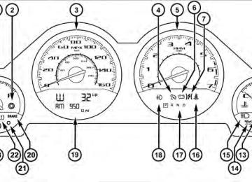
INSTRUMENT CLUSTER
UNDERSTANDING YOUR INSTRUMENT PANEL 175
176 UNDERSTANDING YOUR INSTRUMENT PANEL INSTRUMENT CLUSTER DESCRIPTIONS
1. Fuel Gauge The pointer shows the level of fuel in the fuel tank when the ignition switch is placed in the ON/RUN position. 2. Trip Odometer Button Press this button to change the display from odometer to either of two trip odometer settings. The letter “A” or “B” will appear when in the trip odometer mode. Push in and hold the button for two seconds to reset the trip odometer to 0 miles (km). The odometer must be in TRIP mode to reset it. 3. Speedometer Indicates vehicle speed. 4. Electronic Speed Control Indicator Light
This light will turn on when the electronic speed control is on.
5. Tachometer The red segments indicate the maximum permissible engine revolutions per minute (RPM x 1000) for each gear range. Ease up on the accelerator before reaching the red area. 6. Charging System Warning Light
This light shows the status of the electrical charg- ing system. The light should turn on when the ignition switch is placed in the ON/RUN position and remain on briefly as a bulb check. If the light stays on or turns on while driving, turn off some of the vehicle’s non-essential electrical devices (i.e., radio) or slightly increase engine speed (if at idle). If the light remains on, it means that the charging system is experiencing a problem. See your local authorized dealer to obtain service immediately. If jump starting is required, refer to “Jump Starting Procedures” in “What To Do In Emergencies”.
7. Electronic Throttle Control (ETC) Warning Light
This light will turn on briefly as a bulb check when the ignition switch is placed in the ON/ RUN position. This light will also turn on while the engine is running if there is a problem with
the Electronic Throttle Control (ETC) system. If the light comes on while the engine is running, safely bring the vehicle to a complete stop as soon as possible, place the shift lever in PARK, and cycle the ignition key. The light should turn off. If the light remains lit with the engine running, your vehicle will usually be drivable. However, see an authorized dealer for service as soon as possible.
UNDERSTANDING YOUR INSTRUMENT PANEL 177
If the light is flashing when the engine is running, immediate service is required. In this case, you may experience reduced performance, an elevated/rough idle or engine stall, and your vehicle may require towing. Also, have the system checked by an authorized dealer if the light does not come on during starting. 8. Temperature Gauge The temperature gauge shows engine coolant tempera- ture. Any reading within the normal range indicates that the engine cooling system is operating satisfactorily. The gauge pointer will likely indicate a higher tempera- ture when driving in hot weather, up mountain grades, or when towing a trailer. It should not be allowed to exceed the upper limits of the normal operating range.178 UNDERSTANDING YOUR INSTRUMENT PANEL
CAUTION!
Driving with a hot engine cooling system could damage your vehicle. If the temperature gauge reads “H,” pull over and stop the vehicle. Idle the vehicle with the air conditioner turned off until the pointer drops back into the normal range. If the pointer remains on the “H,” and you hear a chime, turn the engine OFF immediately and call for service.
WARNING!
A hot engine cooling system is dangerous. You or others could be badly burned by steam or boiling coolant. You may want to call a service center if your vehicle overheats. If you decide to look under the hood yourself, refer to “Maintaining Your Vehicle” and follow the warnings under the Cooling System Pressure Cap paragraph.
9. Turn Signal Indicators
The arrow will flash with the exterior turn signal when the turn signal lever is operated.
NOTE: • A continuous chime will sound if the vehicle is driven more than 1 mile (1.6 km) with either turn signal on. • Check for an inoperative outside light bulb if either
indicator flashes at a rapid rate.
10. Air Bag Warning Light
This light will turn on for four to eight seconds as a bulb check when the ignition switch is first turned to the ON/RUN position. If the light is either not on during starting, stays on, or turns on while driving, have the system inspected at an autho- rized dealer as soon as possible. Refer to “Occupant Restraints” in “Things To Know Before Starting Your Vehicle” for further information.
11. Engine Temperature Warning Light
This light will turn on and a single chime will sound to warn of an overheated engine condition. When this light turns on, the engine temperature is critically hot. If the light turns on while driving, safely pull over and stop the vehicle. The vehicle should be turned OFF immediately and serviced as soon as pos- sible. (Refer to “If Your Engine Overheats” in “What To Do In Emergencies” for further information). 12. Electronic Stability Program (ESP)
If this indicator light flashes during accelera- tion, ease up on the accelerator and apply as little throttle as possible. Adapt your speed and driving to the prevailing road conditions, and do not switch off the Electronic Stability Program (ESP).
UNDERSTANDING YOUR INSTRUMENT PANEL 179
13. Electronic Stability Program (ESP) Indicator Light / Brake Assist System (BAS) Warning LightThe malfunction light for the Electronic Stabil- ity Program (ESP) is combined with Brake Assist System (BAS). The yellow “ESP/BAS Warning Light” comes on when the ignition switch is placed in the ON/RUN position. They should go out with the engine running. If the “ESP/BAS Warn- ing Light” comes on continuously with the engine run- ning, a malfunction has been detected in either the ESP or the BAS system. If this light remains on after several ignition cycles, and the vehicle has been driven several miles (kilometers) at speeds greater than 30 mph (48 km/h), see an authorized dealer as soon as possible.
180 UNDERSTANDING YOUR INSTRUMENT PANEL
WARNING!
If the warning light remains on, the system may not be working and you will not have the benefit of ESP or BAS. You should adjust your speed and stopping distance to account for this lack of the feature or you could be in an accident and be seriously injured. You should take your vehicle to an authorized dealer.
14. Oil Pressure Warning Light
This light indicates low engine oil pressure. The light should turn on momentarily when the engine is started. If the light turns on while driving, stop the vehicle and shut off the engine as soon as possible. A chime will sound for four minutes when this light turns on. Do not operate the vehicle until the cause is corrected. This light does not indicate how much oil is in the engine. The engine oil level must be checked under the hood.
15. High Beam Indicator
This indicator will turn on when the high beam headlights are on. Push the multifunction lever away from the steering wheel to switch the headlights to high beam. 16. Seat Belt Reminder Light
This light will turn on for four to eight seconds as a bulb check when the ignition switch is first placed in ON/RUN. A chime will sound if the driver’s seat belt is unbuckled during the bulb check. The Seat Belt Warning Light will flash or remain on continu- ously if the driver’s seat belt remains unbuckled after the bulb check or when driving. Refer to “Occupant Re- straints” in “Things To Know Before Starting Your Ve- hicle” for further information.
17. Shift Lever Indicator — Automatic Transmission Only The Shift Lever Indicator is self-contained within the instrument cluster. It displays the gear position of the automatic transmission. 18. Front Fog Light Indicator — If Equipped
This indicator will illuminate when the front fog lights are on.
19. Odometer / Electronic Vehicle Information Center (EVIC) Display Area The odometer display shows the total distance the ve- hicle has been driven. The trip odometer shows indi- vidual trip mileage. Refer to “Trip Odometer Button” for additional information. NOTE: U.S. Federal regulations require that upon trans- fer of vehicle ownership, the seller certify to the pur- chaser the correct mileage that the vehicle has been driven. If your odometer needs to be repaired or serviced,
UNDERSTANDING YOUR INSTRUMENT PANEL 181
the repair technician should leave the odometer reading the same as it was before the repair or service. If s/he cannot do so, then the odometer must be set at zero, and a sticker must be placed in the door jamb stating what the mileage was before the repair or service. It is a good idea for you to make a record of the odometer reading before the repair/service, so that you can be sure that it is properly reset, or that the door jamb sticker is accurate if the odometer must be reset at zero. Vehicle Odometer Messages When the appropriate conditions exist, the following messages will display in the odometer:ECO . . . . . . . . . . . . . . . . . . . . . . Fuel Saver Indicator gASCAP . . . . . . . . . . . . Loose Fuel Filler Cap Message Lo tirE . . . . . . . . . . . . . . . . . . . . . . Low Tire Pressure noFUSE . . . . . . . . . . . . . . . . . . . . . . . . . . Fuse Fault CHAngE OIL . . . . . . . . . . . . . . . Oil Change Required
182 UNDERSTANDING YOUR INSTRUMENT PANEL This display shows the Electronic Vehicle Information Center (EVIC) messages when the appropriate conditions exist. Refer to Electronic Vehicle Information Center (EVIC) for further information. ECO (Fuel Saver Indicator) — If Equipped The ECO indicator will illuminate when you are driving in a fuel efficient manner and can be used to modify driving habits in order to increase fuel economy. The ECO display will toggle on and off depending on driving habits and vehicle usage. gASCAP If the vehicle diagnostic system determines that the fuel filler cap is loose, improperly installed, or damaged, a “gASCAP” message will display in the odometer display area. Tighten the fuel filler cap properly and press the TRIP ODOMETER button to turn off the message. If the problem continues, the message will appear the next time the vehicle is started.
A loose, improperly installed, or damaged fuel filler cap may also turn on the Malfunction Indicator Light (MIL). Lo tirE When the appropriate condition exists, the odometer display will toggle between Lo and tirE for three cycles. noFUSE If the vehicle diagnostic system determines that the Igni- tion Off Draw (IOD) fuse is improperly installed, or damaged, a “noFUSE” message will display in the odom- eter display area. For further information on fuses and fuse locations refer to “Fuses” in “Maintaining Your Vehicle”. CHAngE OIL (Base Cluster) Your vehicle is equipped with an engine oil change indicator system. The “CHAngE OIL” message will flash in the instrument cluster odometer for approximately 12 seconds after a single chime has sounded to indicate the next scheduled oil change interval. The engine oil change indicator system is duty cycle based, which
means the engine oil change interval may fluctuate dependent upon your personal driving style. Unless reset, this message will continue to display each time you place the ignition switch in the ON/RUN position. To turn off the message temporarily, press and release the TRIP ODOMETER button on the instrument cluster. To reset the oil change indicator system (after performing the scheduled maintenance) perform the following procedure: 1. Place the ignition switch in the ON/RUN position (do not start the engine). 2. Fully depress the accelerator pedal, slowly, three times within 10 seconds. 3. Turn the ignition switch to the OFF position. If the indicator message illuminates when you NOTE: start the engine, the oil change indicator system did not reset. If necessary, repeat these steps.
UNDERSTANDING YOUR INSTRUMENT PANEL 183