- Download PDF Manual
-
Traction Control System (TCS) This system monitors the amount of wheel spin of each driven wheel. If wheel spin is detected, brake pressure is applied to the slipping wheel(s) and engine power is reduced to provide enhanced acceleration and stability.
Brake Assist System (BAS) This system complements the ABS by optimizing the vehicle braking capability during emergency brake ma- neuvers. This system detects an emergency braking situ- ation by sensing the rate and amount of brake application and then applies optimum pressure to the brakes. This can help reduce braking distances. Applying the brakes very quickly results in the best BAS assistance. To receive the benefits of this system, you must apply continuous brake pedal pressure during the stopping sequence. Do not reduce brake pedal pressure unless braking is no longer desired. Once the brake pedal is released, the BAS is deactivated.
WARNING!
The BAS cannot prevent the natural laws of physics from acting on the vehicle, nor can it increase the traction afforded by prevailing road conditions. The BAS cannot prevent collisions, including those re- sulting from excessive speed in turns, driving on very slippery surfaces, or hydroplaning. The capa- bilities of a BAS-equipped vehicle must never be exploited in a reckless or dangerous manner that could jeopardize the user’s safety or the safety of others.
STARTING AND OPERATING 381
Electronic Stability Control (ESC) This system enhances directional control and stability of the vehicle under various driving conditions. The ESC corrects for oversteering and understeering the vehicle by applying the brake of the appropriate wheel. Engine power may also be reduced to assist in counteracting the condition of oversteer or understeer and help the vehicle maintain the desired path. The ESC uses sensors in the vehicle to determine the path that the driver intends to steer the vehicle and compares it to the actual path of the vehicle. When the actual path does not match the intended path, the ESC applies the brake of the appropriate wheel to assist in counteracting the condition of oversteer or understeer. • Oversteer - when the vehicle is turning more than • Understeer - when the vehicle is turning less than
appropriate for the steering wheel position.
appropriate for the steering wheel position.
382 STARTING AND OPERATING ESC Operating Modes The ESC system has two available operating modes: ESC On This is the normal operating mode for the ESC. When- ever the vehicle is started, the ESC system will be in this mode. This mode should be used for most driving conditions. The ESC should only be turned OFF for specific reasons as noted in the following paragraphs. Partial Off The “Partial Off” mode is intended for times when a more spirited driving experience is desired. It is also intended for driving in deep snow, sand, or gravel. This mode disables the TCS portion of the ESC and raises the threshold for ESC activation, which allows for more wheel spin than what ESC normally allows.
The “ESC Off” switch is located on the switch bank in the center of the instrument panel. To enter the “Partial Off” mode, momentarily press the “ESC Off” switch and the “ESC Activation/Malfunction Indicator Light” will illu- minate. To turn the ESC on again, momentarily press the “ESC Off” switch and the “ESC Activation/Malfunction Indicator Light” will turn off. NOTE: To improve the vehicle’s traction when driving with snow chains, or when starting off in deep snow, sand, or gravel, it may be desirable to switch to the “Partial Off” mode by momentarily pressing the “ESC Off” switch. Once the situation requiring “Partial Off” mode is overcome, turn the ESC on again by momen- tarily pressing the “ESC Off” switch. This may be done while the vehicle is in motion.
WARNING!
The Electronic Stability Control (ESC) cannot pre- vent the natural laws of physics from acting on the vehicle, nor can it increase the traction afforded by prevailing road conditions. ESC cannot prevent acci- dents, including those resulting from excessive speed in turns, driving on very slippery surfaces, or hydro- planing. Only a safe, attentive, and skillful driver can prevent accidents. The capabilities of an ESC equipped vehicle must never be exploited in a reck- less or dangerous manner which could jeopardize the user’s safety or the safety of others.
Hill Start Assist (HSA) The HSA system is designed to assist the driver when starting a vehicle from a stop on a hill. HSA will maintain the level of brake pressure the driver applied for a short period of time after the driver takes their foot off of the
STARTING AND OPERATING 383
brake pedal. If the driver does not apply the throttle during this short period of time, the system will release brake pressure and the vehicle will roll down the hill. The system will release brake pressure in proportion to the amount of throttle applied as the vehicle starts to move in the intended direction of travel. HSA Activation Criteria The following criteria must be met in order for HSA to activate: • Vehicle must be stopped. • Vehicle must be on a 6% (approximate) grade or • Gear selection matches vehicle uphill direction (i.e., vehicle facing uphill is in forward gear; vehicle back- ing uphill is in REVERSE gear).greater hill.
384 STARTING AND OPERATING HSA will work in REVERSE and all forward gears when the activation criteria have been met. The system will not activate if the vehicle is placed in NEUTRAL or PARK.
WARNING!
There may be situations on minor hills (i.e., less than 8%), with a loaded vehicle, or while pulling a trailer, when the system will not activate and slight rolling may occur. This could cause a collision with another vehicle or object. Always remember the driver is responsible for braking the vehicle.
Towing With HSA HSA will provide assistance when starting on a grade when pulling a trailer.
WARNING!
• If you use a trailer brake controller with your trailer, your trailer brakes may be activated and deactivated with the brake switch. If so, when the brake pedal is released, there may not be enough brake pressure to hold the vehicle and trailer on a hill and this could cause a collision with another vehicle or object behind you. In order to avoid rolling down the hill while resuming acceleration, manually activate the trailer brake prior to releas- ing the brake pedal. Always remember the driver is responsible for braking the vehicle.
(Continued)
WARNING! (Continued)
• HSA is not a parking brake. If you stop the vehicle on a hill without putting the transmission in PARK and using the parking brake, it will roll down the hill and could cause a collision with another vehicle or object. Always remember to use the parking brake while parking on a hill, and that the driver is responsible for braking the vehicle.
HSA Off If you wish to turn off the HSA system, it can be done using the Customer Programmable Features in the Elec- tronic Vehicle Information Center (EVIC). Refer to “Elec- tronic Vehicle Information Center (EVIC)” in “Under- standing Your Instrument Panel” for further information. Ready Alert Braking Ready Alert Braking may reduce the time required to reach full braking during emergency braking situations.
STARTING AND OPERATING 385
It anticipates when an emergency braking situation may occur by monitoring how fast the throttle is released by the driver. When the throttle is released very quickly, Ready Alert Braking applies a small amount of brake pressure. This brake pressure will not be noticed by the driver. The brake system uses this brake pressure to allow a fast brake response if the driver applies the brakes. Rain Brake Support Rain Brake Support may improve braking performance in wet conditions. It will periodically apply a small amount of brake pressure to remove any water buildup on the front brake rotors. It only functions when the windshield wipers are in the LO or HI mode, it does not function in the intermittent mode. When Rain Brake Support is active, there is no notification to the driver and no driver interaction is required.386 STARTING AND OPERATING ESC Activation/Malfunction Indicator Light and ESC OFF Indicator Light
The “ESC Activation/Malfunction Indicator Light” in the instrument cluster will come on when the ignition switch is turned to the ON position. It should go out with the engine running. If the “ESC Activation/Malfunction Indicator Light” comes on continuously with the engine running, a malfunction has been detected in the ESC system. If this light remains on after several ignition cycles, and the vehicle has been driven several miles (kilometers) at speeds greater than 30 mph (48 km/h), see your autho- rized dealer as soon as possible to have the problem diagnosed and corrected. The “ESC Activation/Malfunction Indicator Light” (lo- cated in the instrument cluster) starts to flash as soon as the tires lose traction and the ESC system becomes active. The “ESC Activation/Malfunction Indicator Light” also flashes when TCS is active. If the “ESC Activation/
Malfunction Indicator Light” begins to flash during ac- celeration, ease up on the accelerator and apply as little throttle as possible. Be sure to adapt your speed and driving to the prevailing road conditions. NOTE: • The “ESC Activation/Malfunction Indicator Light” and the “ESC OFF Indicator Light” come on momen- tarily each time the ignition switch is turned ON. • Each time the ignition is turned ON, the ESC system • The ESC system will make buzzing or clicking sounds when it is active. This is normal; the sounds will stop when ESC becomes inactive following the maneuver that caused the ESC activation.
will be ON even if it was turned off previously.
The “ESC OFF Indicator Light” indicates the Electronic Stability Control (ESC) is off.
Synchronizing ESC
the
If the power supply is interrupted (battery disconnected or discharged), “ESC Activation/Malfunction Indicator Light” may illuminate with the engine running. If this should occur, turn the steering wheel completely to the left and then to the right. The “ESC Activation/ Malfunction Indicator Light” should go out. However, if the light remains on, have the ESC and BAS checked at your authorized dealer as soon as possible.
STARTING AND OPERATING 387
TIRE SAFETY INFORMATION
Tire Markings
1 — U.S. DOT Safety Stan- dards Code (TIN) 2 — Size Designation 3 — Service Description
4 — Maximum Load
5 — Maximum Pressure 6 — Treadwear, Traction and Temperature Grades
• Temporary spare tires are spares designed for tempo- rary emergency use only. Temporary high pressure compact spare tires have the letter “T” or “S” molded into the sidewall preceding the size designation. Ex- ample: T145/80D18 103M. • High flotation tire sizing is based on U.S. design standards and it begins with the tire diameter molded into the sidewall. Example: 31x10.5 R15 LT.
388 STARTING AND OPERATING NOTE: • P (Passenger) - Metric tire sizing is based on U.S. design standards. P-Metric tires have the letter “P” molded into the sidewall preceding the size designa- tion. Example: P215/65R15 95H. • European-Metric tire sizing is based on European design standards. Tires designed to this standard have the tire size molded into the sidewall beginning with the section width. The letter ⬙P⬙ is absent from this tire size designation. Example: 215/65R15 96H. • LT (Light Truck) - Metric tire sizing is based on U.S. design standards. The size designation for LT-Metric tires is the same as for P-Metric tires except for the letters “LT” that are molded into the sidewall preced- ing the size designation. Example: LT235/85R16.
Tire Sizing Chart
Size Designation:
EXAMPLE:
P = Passenger car tire size based on U.S. design standards ⴖ....blank....ⴖ = Passenger car tire based on European design standards LT = Light truck tire based on U.S. design standards T or S = Temporary spare tire 31 = Overall diameter in inches (in) 215 = Section width in millimeters (mm) 65 = Aspect ratio in percent (%)
— Ratio of section height to section width of tire
10.5 = Section width in inches (in) R = Construction code
— ⬙R⬙ means radial construction — ⬙D⬙ means diagonal or bias construction
15 = Rim diameter in inches (in)
STARTING AND OPERATING 389
390 STARTING AND OPERATING
Service Description:
95 = Load Index
EXAMPLE:
— A numerical code associated with the maximum load a tire can carry
H = Speed Symbol
— A symbol indicating the range of speeds at which a tire can carry a load corresponding to its load index under certain operating conditions — The maximum speed corresponding to the speed symbol should only be achieved under specified operating conditions (i.e., tire pressure, vehicle loading, road conditions, and posted speed limits)
Load Identification:
ⴖ....blank....ⴖ = Absence of any text on the sidewall of the tire indicates a Standard Load (SL) tire Extra Load (XL) = Extra load (or reinforced) tire Light Load (LL) = Light load tire C, D, E, F, G = Load range associated with the maximum load a tire can carry at a specified pressure
Maximum Load — Maximum load indicates the maximum load this tire is designed to carry Maximum Pressure — Maximum pressure indicates the maximum permissible cold tire inflation pressure for this tire
Tire Identification Number (TIN) The TIN may be found on one or both sides of the tire, however, the date code may only be on one side. Tires with white sidewalls will have the full TIN, including the date code, located on the white sidewall side of the tire.
STARTING AND OPERATING 391
Look for the TIN on the outboard side of black sidewall tires as mounted on the vehicle. If the TIN is not found on the outboard side, then you will find it on the inboard side of the tire.DOT = Department of Transportation
— This symbol certifies that the tire is in compliance with the U.S. Department of Transportation tire safety standards and is approved for highway use
EXAMPLE:
DOT MA L9 ABCD 0301
MA = Code representing the tire manufacturing location (two digits) L9 = Code representing the tire size (two digits) ABCD = Code used by the tire manufacturer (one to four digits) 03 = Number representing the week in which the tire was manufactured (two digits)
—03 means the 3rd week.
01 = Number representing the year in which the tire was manufactured (two digits)
—01 means the year 2001
— Prior to July 2000, tire manufacturers were only required to have one number to represent the year in which the tire was manufactured. Example: 031 could represent the 3rd week of 1981 or 1991392 STARTING AND OPERATING Tire Terminology And Definitions
B-Pillar
Term
Cold Tire Inflation Pressure
Maximum Inflation Pressure
Recommended Cold Tire Inflation Pres- sure Tire Placard
Definition
The vehicle B-Pillar is the structural member of the body located behind the front door. Cold tire inflation pressure is defined as the tire pressure after the vehicle has not been driven for at least 3 hours, or driven less than 1 mile (1.6 km) after sitting for a three hour period. Inflation pressure is measured in units of PSI (pounds per square inch) or kPa (kilopascals). The maximum inflation pressure is the maximum permissible cold tire inflation pressure for this tire. The maximum inflation pres- sure is molded into the sidewall. Vehicle manufacturer’s recommended cold tire inflation pressure as shown on the tire placard. A paper label permanently attached to the vehicle describing the vehicle’s loading capacity, the original equipment tire sizes and the recommended cold tire inflation pressures.
Tire Loading And Tire Pressure
Tire And Loading Information Placard
STARTING AND OPERATING 393
Tire And Loading Information Placard Location NOTE: The proper cold tire inflation pressure is listed on the driver’s side B-Pillar or the rear edge of the driver’s side door.
Tire and Loading Information Placard
This placard tells you important information about the: 1) number of people that can be carried in the vehicle 2) total weight your vehicle can carry 3) tire size designed for your vehicle 4) cold tire inflation pressures for the front, rear, and spare tires.
Tire Placard Location
394 STARTING AND OPERATING Loading The vehicle maximum load on the tire must not exceed the load carrying capacity of the tire on your vehicle. You will not exceed the tire’s load carrying capacity if you adhere to the loading conditions, tire size, and cold tire inflation pressures specified on the Tire and Loading Information placard and in the “Vehicle Loading” section of this manual. NOTE: Under a maximum loaded vehicle condition, gross axle weight ratings (GAWRs) for the front and rear axles must not be exceeded. For further information on GAWRs, vehicle loading, and trailer towing, refer to “Vehicle Loading” in this section. To determine the maximum loading conditions of your vehicle, locate the statement “The combined weight of occupants and cargo should never exceed XXX lbs or XXX kg” on the Tire and Loading Information placard.
The combined weight of occupants, cargo/luggage and trailer tongue weight (if applicable) should never exceed the weight referenced here. Steps For Determining Correct Load Limit 1. Locate the statement “The combined weight of occu- pants and cargo should never exceed XXX lbs or XXX kg” on your vehicle’s placard. 2. Determine the combined weight of the driver and passengers that will be riding in your vehicle. 3. Subtract the combined weight of the driver and pas- sengers from XXX lbs or XXX kg.
4. The resulting figure equals the available amount of cargo and luggage load capacity. For example, if “XXX” amount equals 1,400 lbs (635 kg) and there will be five 150 lb (68 kg) passengers in your vehicle, the amount of available cargo and luggage load capacity is 650 lbs (295 kg) (since 5 x 150 = 750, and 1400 – 750 = 650 lbs [295 kg]). 5. Determine the combined weight of luggage and cargo being loaded on the vehicle. That weight may not safely exceed the available cargo and luggage load capacity calculated in Step 4. 6. If your vehicle will be towing a trailer, load from your trailer will be transferred to your vehicle. Consult this manual to determine how this reduces the available cargo and luggage load capacity of your vehicle.
STARTING AND OPERATING 395
NOTE: • The following table shows examples on how to calcu- late total load, cargo/luggage, and towing capacities of your vehicle with varying seating configurations and number and size of occupants. This table is for illustration purposes only and may not be accurate for the seating and load carry capacity of your vehicle. • For the following example, the combined weight of occupants and cargo should never exceed 865 lbs (392 kg).
396 STARTING AND OPERATING
WARNING!
Safety
STARTING AND OPERATING 397
Overloading of your tires is dangerous. Overloading can cause tire failure, affect vehicle handling, and increase your stopping distance. Use tires of the recommended load capacity for your vehicle. Never overload them.
TIRES — GENERAL INFORMATION
Tire Pressure Proper tire inflation pressure is essential to the safe and satisfactory operation of your vehicle. Three primary areas are affected by improper tire pressure:
WARNING!
cause collisions.
sult in tire over-heating and failure.
• Improperly inflated tires are dangerous and can • Under-inflation increases tire flexing and can re- • Over-inflation reduces a tire’s ability to cushion shock. Objects on the road and chuckholes can cause damage that result in tire failure. • Over-inflated or under-inflated tires can affect vehicle handling and can fail suddenly, resulting in loss of vehicle control. • Unequal tire pressures can cause steering prob-
lems. You could lose control of your vehicle.
(Continued)
398 STARTING AND OPERATING
WARNING! (Continued)
• Unequal tire pressures from one side of the ve- hicle to the other can cause the vehicle to drift to the right or left. • Always drive with each tire inflated to the recom-
mended cold tire inflation pressure.
Economy Improper inflation pressures can cause uneven wear patterns to develop across the tire tread. These abnormal wear patterns will reduce tread life resulting in a need for earlier tire replacement. Under-inflation also increases tire fuel rolling consumption. Ride Comfort And Vehicle Stability Proper tire inflation contributes to a comfortable ride. Over-inflation produces a jarring and uncomfortable ride.
resistance
resulting
higher
in
Tire Inflation Pressures The proper cold tire inflation pressure is listed on the driver’s side “B” Pillar or rear edge of the driver’s side door. Some vehicles may have Supplemental Tire Pressure Information for vehicle loads that are less than the maximum loaded vehicle condition. These pressure con- ditions will be found in the “Supplemental Tire Pressure Information” section of this manual. The pressure should be checked and adjusted as well as inspecting for signs of tire wear or visible damage at least once a month. Use a good quality pocket-type gauge to check tire pressure. Do not make a visual judgement when determining proper inflation. Radial tires may look properly inflated even when they are under-inflated.
CAUTION!
After inspecting or adjusting the tire pressure, al- ways reinstall the valve stem cap. This will prevent moisture and dirt from entering the valve stem, which could damage the valve stem.
Inflation pressures specified on the placard are always “cold tire inflation pressure.” Cold tire inflation pressure is defined as the tire pressure after the vehicle has not been driven for at least three hours, or driven less than 1 mile (1.6 km) after a three hour period. The cold tire inflation pressure must not exceed the maximum infla- tion pressure molded into the tire sidewall. Check tire pressures more often if subject to a wide range of outdoor temperatures, as tire pressures vary with temperature changes.
STARTING AND OPERATING 399
Tire pressures change by approximately 1 psi (7 kPa) per 12°F (7°C) of air temperature change. Keep this in mind when checking tire pressure inside a garage, especially in the Winter. Example: If garage temperature = 68°F (20°C) and the outside temperature = 32°F (0°C) then the cold tire inflation pressure should be increased by 3 psi (21 kPa), which equals 1 psi (7 kPa) for every 12°F (7°C) for this outside temperature condition. Tire pressure may increase from 2 to 6 psi (13 to 40 kPa) during operation. DO NOT reduce this normal pressure build up or your tire pressure will be too low.400 STARTING AND OPERATING Tire Pressures For High Speed Operation The manufacturer advocates driving at safe speeds within posted speed limits. Where speed limits or condi- tions are such that the vehicle can be driven at high speeds, maintaining correct tire inflation pressure is very important. Increased tire pressure and reduced vehicle loading may be required for high-speed vehicle opera- tion. Refer to original equipment or an authorized tire dealer for recommended safe operating speeds, loading and cold tire inflation pressures.
WARNING!
High speed driving with your vehicle under maxi- mum load is dangerous. The added strain on your tires could cause them to fail. You could have a serious collision. Do not drive a vehicle loaded to the maximum capacity at continuous speeds above 75 mph (120 km/h).
Radial Ply Tires
WARNING!
Combining radial ply tires with other types of tires on your vehicle will cause your vehicle to handle poorly. The instability could cause a collision. Al- ways use radial ply tires in sets of four. Never combine them with other types of tires.
Cuts and punctures in radial tires are repairable only in the tread area because of sidewall flexing. Consult your authorized tire dealer for radial tire repairs. Spare Tire Matching Original Equipped Tire And Wheel – If Equipped Your vehicle may be equivalent with a spare tire and wheel in look and function as the original equipment tire and wheel found on the front or rear axle of your vehicle. This spare tire may be used in the tire rotation for your
vehicle. If your vehicle has this option refer to an authorized tire dealer for the recommended tire rotation pattern. If your vehicle is not equipped with an original equip- ment tire and wheel as a spare, a non-matching tempo- rary emergency use spare may be equipped with your vehicle. Temporary use spares are engineered to be used only with your vehicle. Your vehicle may be equipped with one of the following types of non-matching tempo- rary use spares; compact, full size, or limited-use. Do not install more than one non-matching temporary use spare tire/wheel on the vehicle at any given time.
CAUTION!
Because of the reduced ground clearance, do not take your vehicle through an automatic car wash with a compact, full size or limited-use temporary spare installed. Damage to the vehicle may result.
STARTING AND OPERATING 401
Compact Spare Tire – If Equipped The compact spare is for temporary emergency use only. You can identify if your vehicle is equipped with a compact spare by looking at the spare tire description on the Tire and Loading Information Placard located on the driver’s side door opening or on the sidewall of the tire. Compact spare tire descriptions begin with the letter “T” or “S” preceding the size designation. Example: T145/ 80D18 103M. T, S = Temporary Spare Tire Since this tire has limited tread life the original equip- ment tire should be repaired (or replaced) and reinstalled on your vehicle at the first opportunity. Do not install a wheel cover or attempt to mount a conventional tire on the compact spare wheel, since the wheel is designed specifically for the compact spare tire. Do not install more than one compact spare tire and wheel on the vehicle at any given time
402 STARTING AND OPERATING
WARNING!
Compact spares are for temporary emergency use only. With these spares, do not drive more than 50 mph (80 km/h). Temporary use spares have limited tread life. When the tread is worn to the tread wear indicators, the temporary use spare tire needs to be replaced. Be sure to follow the warnings, which apply to your spare. Failure to do so could result in spare tire failure and loss of vehicle control.
Full Size Spare – If Equipped The full size spare is for temporary emergency use only. This tire may look like the original equipped tire on the front or rear axle of your vehicle, but it is not. This spare tire may have limited tread life. When the tread is worn to the tread wear indicators, the temporary use full size spare tire needs to be replaced. Since it is not the same as
your original equipment tire, replace (or repair) the original equipment tire and reinstall on the vehicle at the first opportunity. Limited-Use Spare – If Equipped The limited-use spare tire is for temporary emergency use only. This tire is identified by a label located on the limited-use spare wheel. This label contains the driving limitations for this spare. This tire may look like the original equipped tire on the front or rear axle of your vehicle, but it is not. Installation of this limited-use spare tire affects vehicle handling. Since it is not the same as your original equipment tire, replace (or repair) the original equipment tire and reinstall on the vehicle at the first opportunity.
WARNING!
Limited-use spares are for emergency use only. In- stallation of this limited-use spare tire affects vehicle handling. With this tire, do not drive more than the speed listed on the limit-use spare wheel. Keep inflated to the cold tire inflation pressure listed on your Tire and Loading Information Placard located on the driver’s side door opening. Replace (or repair) the original equipment tire at the first opportunity and reinstall it on your vehicle. Failure to do so could result in loss of vehicle control.
STARTING AND OPERATING 403
Tire Spinning When stuck in mud, sand, snow, or ice conditions, do not spin your vehicle’s wheels faster than 30 mph (48 km/h) or for longer than 30 seconds continuously without stopping when you are stuck.
WARNING!
Fast spinning tires can be dangerous. Forces gener- ated by excessive wheel speeds may cause tire dam- age or failure. A tire could explode and injure some- one. Do not spin your vehicle’s wheels faster than 30 mph (48 km/h) or for more than 30 seconds continuously when you are stuck, and do not let anyone near a spinning wheel, no matter what the speed.
404 STARTING AND OPERATING Tread Wear Indicators Tread wear indicators are in the original equipment tires to help you in determining when your tires should be replaced.
These indicators are molded into the bottom of the tread grooves. They will appear as bands when the tread depth becomes 1/16 in (2 mm). When the tread is worn to the tread wear indicators, the tire should be replaced. Life Of Tire The service life of a tire is dependent upon varying factors including, but not limited to: • Driving style • Tire pressure • Distance driven
1 — Worn Tire 2 — New Tire
WARNING!
Tires and the spare tire should be replaced after six years, regardless of the remaining tread. Failure to follow this warning can result in sudden tire failure. You could lose control and have a collision resulting in serious injury or death.
Keep dismounted tires in a cool, dry place with as little exposure to light as possible. Protect tires from contact with oil, grease, and gasoline. Replacement Tires The tires on your new vehicle provide a balance of many characteristics. They should be inspected regularly for wear and correct cold tire inflation pressure. The manu- facturer strongly recommends that you use tires equiva- lent to the originals in size, quality and performance when replacement is needed. (Refer to the paragraph on “Tread Wear Indicators”). Refer to the “Tire and Loading
STARTING AND OPERATING 405
Information” placard for the size designation of your tire. The Load Index and Speed Symbol for your tire will be found on the original equipment tire sidewall. See the Tire Sizing Chart example found in the Tire Safety Information section of this manual for more information relating to the Load Index and Speed Symbol of a tire. It is recommended to replace the two front tires or two rear tires as a pair. Replacing just one tire can seriously affect your vehicle’s handling. If you ever replace a wheel, make sure that the wheel’s specifications match those of the original wheels. It is recommended you contact your original equipment or an authorized tire dealer with any questions you may have on tire specifications or capability. Failure to use equivalent replacement tires may adversely affect the safety, handling, and ride of your vehicle.406 STARTING AND OPERATING
WARNING!
• Do not use a tire, wheel size or rating other than that specified for your vehicle. Some combinations of unapproved tires and wheels may change sus- pension dimensions and performance characteris- tics, resulting in changes to steering, handling, and braking of your vehicle. This can cause unpredict- able handling and stress to steering and suspen- sion components. You could lose control and have a collision resulting in serious injury or death. Use only the tire and wheel sizes with load ratings approved for your vehicle. • Never use a tire with a smaller load index or capacity, other than what was originally equipped on your vehicle. Using a tire with a smaller load index could result in tire overloading and failure. You could lose control and have a collision.
(Continued)
WARNING! (Continued)
• Failure to equip your vehicle with tires having adequate speed capability can result in sudden tire failure and loss of vehicle control.
CAUTION!
Replacing original tires with tires of a different size may result in false speedometer and odometer readings.
TIRE CHAINS Use only compact chains or other traction aids that meet SAE type “Class S” specifications. Chains must be the proper size for the vehicle, as recommended by the chain manufacturer. Install tire chains only on P215/65R17
using standard chains, on P225/60R18 and P235/55R18
using model 0143 (tirechaindealer.com) and on P235/ 55R19 using model Z-575 (scc-chain.com).NOTE: Do not use tire chains on a compact spare tire.
CAUTION!
To avoid damage to your vehicle or tires, observe the following precautions: • Because of restricted chain clearance between tires and other suspension components, it is important that only chains in good condition are used. Bro- ken chains can cause serious damage. Stop the vehicle immediately if noise occurs that could indicate chain breakage. Remove the damaged parts of the chain before further use. • Install chains on the rear wheels as tightly as possible and then retighten after driving about 1⁄2
mile (0.8 km).• Do not exceed 30 mph (48 km/h).
(Continued)
STARTING AND OPERATING 407
CAUTION! (Continued)
ment.
bumps, especially with a loaded vehicle.
• Drive cautiously and avoid severe turns and large • Use on rear wheels only. • Do not drive for prolonged period on dry pave- • Observe the tire chain manufacturer’s instructions on the method of installation, operating speed, and conditions for use. Always use the lower suggested operating speed of the chain manufac- turer if different from the speed recommended by the manufacture.
In order to avoid damage to tires, chains, and NOTE: your vehicle do not drive for a prolonged period on dry pavement. Observe the tire chain manufacturer’s instruc- tions on method of installation, operating speed, and conditions for usage.
408 STARTING AND OPERATING Always use the lower suggested operating speed if both the chain manufacturer and vehicle manufacturer sug- gest a maximum speed. This notice applies to all chain traction devices, including link and cable (radial) chains.
SNOW TIRES Some areas of the country require the use of snow tires during the winter. All season tires can be identified by the M+S designation on the tire sidewall. If you need snow tires, select tires equivalent in size and type to the original equipment tires. Use snow tires only in sets of four. Failure to do so may adversely affect the safety and handling of your vehicle.
Snow tires generally have lower speed ratings than what was originally equipped with your vehicle and should not be operated at sustained speeds over 75 mph (120 km/h). For speeds above 75 mph (120 km/h) refer to original equipment or an authorized tire dealer for recommended safe operating speeds, loading and cold tire inflation pressures. While studded tires improve performance on ice, skid and traction capability on wet or dry surfaces may be poorer than that of non-studded tires. Some states pro- hibit studded tires; local laws should be checked before using these tire types.
therefore,
TIRE ROTATION RECOMMENDATIONS Tires on the front and rear axles of vehicles operate at different loads and perform different steering, driving, and braking functions. For these reasons, they wear at unequal rates. These effects can be reduced by timely rotation of tires. The benefits of rotation are especially worthwhile with aggressive tread designs such as those on all season type tires. Rotation will increase tread life, help to maintain mud, snow and wet traction levels, and contribute to a smooth, quiet ride. Refer to the “Maintenance Schedule” for the proper maintenance intervals. The reasons for any rapid or unusual wear should be corrected prior to rotation being performed.
STARTING AND OPERATING 409
The suggested rotation method is the “forward cross” shown in the following diagram. This rotation pattern does not apply to some directional tires that must not be reversed.Tire Rotation
410 STARTING AND OPERATING TIRE PRESSURE MONITOR SYSTEM (TPMS) The Tire Pressure Monitor System (TPMS) will warn the driver of a low tire pressure based on the vehicle recom- mended cold placard pressure. The tire pressure will vary with temperature by about 1 psi (6.9 kPa) for every 12°F (6.5°C). This means that when the outside temperature decreases, the tire pressure will decrease. Tire pressure should always be set based on cold inflation tire pressure. This is defined as the tire pressure after the vehicle has not been driven for at least three hours, or driven less than 1 mile (1.6 km) after a three hour period. The cold tire inflation pressure must not exceed the maximum inflation pressure molded into the tire sidewall. Refer to “Tires – General Information” in “Starting and Operating” for information on how to properly inflate the vehicle’s tires. The tire pressure will also increase as the vehicle is driven - this is normal and there should be no adjustment for this increased pres- sure.
The TPMS will warn the driver of a low tire pressure if the tire pressure falls below the low-pressure warning limit for any reason, including low temperature effects and natural pressure loss through the tire. The TPMS will continue to warn the driver of low tire pressure as long as the condition exists, and will not turn off until the tire pressure is at or above the recommended cold placard pressure. Once the low tire pressure warn- ing (Tire Pressure Monitoring [TPM] Telltale Light) illu- minates, you must increase the tire pressure to the recommended cold placard pressure in order for the TPM Telltale Light to turn off. The system will automatically update and the TPM Telltale Light will turn off once the system receives the updated tire pressures. The vehicle may need to be driven for up to 20 minutes above 15 mph (24 km/h) in order for the TPMS to receive this informa- tion.
For example, your vehicle may have a recommended cold (parked for more than three hours) placard pressure of 30 psi (207 kPa). If the ambient temperature is 68°F (20°C) and the measured tire pressure is 27 psi (186 kPa), a temperature drop to 20°F (-7°C) will decrease the tire pressure to approximately 23 psi (158 kPa). This tire pressure is sufficiently low enough to turn ON the TPM Telltale Light. Driving the vehicle may cause the tire pressure to rise to approximately 27 psi (186 kPa), but the TPM Telltale Light will still be ON. In this situation, the TPM Telltale Light will turn OFF only after the tires are inflated to the vehicle’s recommended cold placard pres- sure value.
STARTING AND OPERATING 411
CAUTION!
• The TPMS has been optimized for the original equipment tires and wheels. TPMS pressures and warning have been established for the tire size equipped on your vehicle. Undesirable system operation or sensor damage may result when us- ing replacement equipment that is not of the same size, type, and/or style. Aftermarket wheels can cause sensor damage. Do not use aftermarket tire sealants or balance beads if your vehicle is equipped with a TPMS, as damage to the sensors may result. • After inspecting or adjusting the tire pressure, always reinstall the valve stem cap. This will prevent moisture and dirt from entering the valve stem, which could damage the TPM sensor.
while adjusting your tire pressure.
412 STARTING AND OPERATING NOTE: • The TPMS is not intended to replace normal tire care and maintenance or to provide warning of a tire failure or condition. • The TPMS should not be used as a tire pressure gauge • Driving on a significantly under-inflated tire causes the tire to overheat and can lead to tire failure. Under-inflation also reduces fuel efficiency and tire tread life, and may affect the vehicle’s handling and stopping ability. • The TPMS is not a substitute for proper tire mainte- nance, and it is the driver’s responsibility to maintain correct tire pressure using an accurate tire pressure gauge, even if under-inflation has not reached the level to trigger illumination of the TPM Telltale Light.
• Seasonal temperature changes will affect tire pressure, and the TPMS will monitor the actual tire pressure in the tire.
Base System The Tire Pressure Monitor System (TPMS) uses wireless technology with wheel rim mounted electronic sensors to monitor tire pressure levels. Sensors mounted to each wheel as part of the valve stem transmit tire pressure readings to the receiver module. It is particularly important for you to check the NOTE: tire pressure in all of the tires on your vehicle monthly and to maintain the proper pressure. The TPMS consists of the following components: • Receiver module, • Four TPM sensors, and • TPM Telltale Light
The matching full size spare wheel and tire assembly (if equipped) has a TPM sensor. The matching full size spare can be used in place of any of the four road tires. The TPMS will only monitor the pressure in the full size spare when it is used in place of a road tire. Otherwise, a spare with a pressure below the low-pressure limit will not cause the TPM Telltale Light to illuminate or the chime to sound. Tire Pressure Monitoring Low Pressure Warnings
The TPM Telltale Light will illuminate in the instrument cluster, a ⬙LOW TIRE⬙ message will be displayed and a chime will sound when tire pres- sure is low in one or more of the four active road tires. Should this occur, you should stop as soon as possible, check the inflation pressure of each tire on your vehicle, and inflate each tire to the vehicle’s recommended cold placard pressure value. Once the system receives the updated tire pressures, the system will automatically update and the TPM Telltale Light and ⬙LOW TIRE⬙
STARTING AND OPERATING 413
message will turn off. The vehicle may need to be driven for up to 20 minutes above 15 mph (24 km/h) in order for the TPMS to receive this information. Service TPMS Warning If a system fault is detected, the TPM Telltale Light will flash on and off for 75 seconds and then remain on solid. The system fault will also sound a chime. If the ignition switch is cycled, this sequence will repeat, providing the system fault still exists. The TPM Telltale Light will turn off when the fault condition no longer exists. A system fault can occur due to any of the following: 1. Signal interference due to electronic devices or driving next to facilities emitting the same radio frequencies as the TPM sensors. 2. Installing aftermarket window tinting that contains materials that may block radio wave signals.414 STARTING AND OPERATING 3. Accumulation of snow or ice around the wheels or wheel housings. 4. Using tire chains on the vehicle. 5. Using wheels/tires not equipped with TPM sensors. Vehicles With Full Size Spare 1. The matching full size spare wheel and tire assembly has a TPM sensor that can be monitored by the TPMS. 2. If you install the full size spare in place of a road tire that has a pressure below the low-pressure warning limit, upon the next ignition switch cycle, a chime will sound and the TPM Telltale Light and ⬙LOW TIRE⬙ message will turn ON. 3. Driving the vehicle for up to 20 minutes above 15 mph (24 km/h) will turn off the TPM Telltale Light and ⬙LOW TIRE⬙ message as long as no tire pressure is below the low-pressure warning limit in any of the four active road tires.
Vehicles With Compact Spare 1. The compact spare tire does not have a TPM sensor. Therefore, the TPMS will not monitor the pressure in the compact spare tire. 2. If you install the compact spare tire in place of a road tire that has a pressure below the low-pressure warning limit, upon the next ignition switch cycle, a chime will sound and the TPM Telltale Light and ⬙LOW TIRE⬙ message will turn ON. 3. After driving the vehicle for up to 20 minutes above 15 mph (24 km/h), the ⬙LOW TIRE⬙ message will turn off and the TPM Telltale Light will flash on and off for 75 seconds and then remain on solid. 4. For each subsequent ignition switch cycle, a chime will sound and the TPM Telltale Light will flash on and off for 75 seconds and then remain on solid.
5. Once you repair or replace the original road tire, and reinstall it on the vehicle in place of the compact spare, the TPMS will update automatically and the TPM Telltale Light will turn OFF, as long as no tire pressure is below the low-pressure warning limit in any of the four active road tires. The vehicle may need to be driven for up to 20 minutes above 15 mph (24 km/h) in order for the TPMS to receive this information. Premium System – If Equipped The Tire Pressure Monitor System (TPMS) uses wireless technology with wheel rim mounted electronic sensors to monitor tire pressure levels. Sensors mounted to each wheel as part of the valve stem transmit tire pressure readings to the receiver module. It is particularly important for you to check the NOTE: tire pressure in all of the tires on your vehicle monthly and to maintain the proper pressure.
STARTING AND OPERATING 415
tronic Vehicle Information Center (EVIC), and
The TPMS consists of the following components: • Receiver module, • Four TPM sensors, • Various TPMS messages, which display in the Elec- • TPM Telltale Light The matching full size spare wheel and tire assembly (if equipped) has a TPM sensor. The full size spare can be used in place of any of the four road tires. The TPMS will only monitor the pressure in the full size spare tire when it is used in place of a road tire. Otherwise, a spare with a pressure below the low-pressure limit will not cause the TPM Telltale Light to illuminate or the chime to sound.
416 STARTING AND OPERATING Tire Pressure Monitoring Low Pressure Warnings
The TPM Telltale Light will illuminate in the instrument cluster and a chime will sound when tire pressure is low in one or more of the four active road tires. In addition, the EVIC will display a ⬙LOW TIRE⬙ message and a graphic showing the pres- sure values of each tire with the low tire pressure values flashing or changing color.
Should this occur, you should stop as soon as possible and inflate the tires with a low pressure condition (those flashing or in a different color in the EVIC graphic) to the vehicle’s recommended cold placard pressure inflation value. Once the system receives the updated tire pres- sures, the system will automatically update, the graphic display in the EVIC will stop flashing or change color back to the original color, and the TPM Telltale Light will turn off. The vehicle may need to be driven for up to 20 minutes above 15 mph (24 km/h) in order for the TPMS to receive this information. Service TPMS Warning If a system fault is detected, the TPM Telltale Light will flash on and off for 75 seconds and then remain on solid. The system fault will also sound a chime. In addition, the EVIC will display a ⬙SERVICE TPM SYSTEM⬙ message for a minimum of five seconds and then display dashes (- -) in place of the pressure value to indicate which sensor is not being received.
STARTING AND OPERATING 417
1. Signal interference due to electronic devices or driving next to facilities emitting the same radio frequencies as the TPM sensors. 2. Installing aftermarket window tinting that contains materials that may block radio wave signals. 3. Accumulation of snow or ice around the wheels or wheel housings. 4. Using tire chains on the vehicle. 5. Using wheels/tires not equipped with TPM sensors. The EVIC will also display a ⬙SERVICE TPM SYSTEM⬙ message for a minimum of five seconds when a system fault related to an incorrect sensor location fault is detected. In this case, the ⬙SERVICE TPM SYSTEM⬙ message is then followed with a graphic display with pressure values still shown. This indicates that the pres- sure values are still being received from the TPM sensors but they may not be located in the correct vehicleIf the ignition switch is cycled, this sequence will repeat, providing the system fault still exists. If the system fault no longer exists, the TPM Telltale Light will no longer flash, and the ⬙SERVICE TPM SYSTEM⬙ message will no longer display, and a pressure value will display in place of the dashes. A system fault can occur due to any of the following:
418 STARTING AND OPERATING position. The system still needs to be serviced as long as the ⬙SERVICE TPM SYSTEM⬙ message is displayed. Vehicles With Full Size Spare 1. The matching full size spare wheel and tire assembly has a TPM sensor that can be monitored by the TPMS. 2. If you install the full size spare in place of a road tire that has a pressure below the low-pressure warning limit, upon the next ignition switch cycle, a chime will sound and the TPM Telltale Light will turn ON. In addition, the EVIC will display a low pressure message and a graphic showing the low tire pressure value flashing or in a different color. 3. After driving the vehicle for up to 20 minutes above 15 mph (24 km/h) the TPM Telltale Light will turn OFF, and the pressure value displayed will be updated and stop flashing or return to its original color as long as no tire pressure is below the low-pressure warning limit in any of the four active road tires.
Vehicles With Compact Spare 1. The compact spare tire does not have a TPM sensor. Therefore, the TPMS will not monitor the pressure in the compact spare tire. 2. If you install the compact spare tire in place of a road tire that has a pressure below the low-pressure warning limit, upon the next ignition switch cycle, the TPM Telltale Light will remain ON and a chime will sound. In addition, the graphic in the EVIC will still display a flashing pressure value or a pressure value in a different color. 3. After driving the vehicle for up to 20 minutes above 15 mph (24 km/h), the TPM Telltale Light will flash on and off for 75 seconds and then remain on solid. In addition, the EVIC will display a ⬙SERVICE TPM SYS- TEM⬙ message for a minimum of five seconds and then display dashes (- -) in place of the pressure value.
4. For each subsequent ignition switch cycle, a chime will sound, the TPM Telltale Light will flash on and off for 75 seconds and then remain on solid, and the EVIC will display a ⬙SERVICE TPM SYSTEM⬙ message for a mini- mum of five seconds and then display dashes (- -) in place of the pressure value. 5. Once you repair or replace the original road tire and reinstall it on the vehicle in place of the compact spare, the TPMS will update automatically. In addition, the TPM Telltale Light will turn OFF and the graphic in the EVIC will display a new pressure value instead of dashes (- -), as long as no tire pressure is below the low-pressure warning limit in any of the four active road tires. The vehicle may need to be driven for up to 20 minutes above 15 mph (24 km/h) in order for the TPMS to receive this information.
STARTING AND OPERATING 419
General Information This device complies with Part 15 of the FCC rules and RSS 210 of Industry Canada. Operation is subject to the following conditions: • This device may not cause harmful interference. • This device must accept any interference received, including interference that may cause undesired operation.
The TPM sensors are regulated under one of the follow- ing licenses:
United States . . . . . . . . . . . . . . . . . . . MRXC4W4MA4
Canada . . . . . . . . . . . . . . . . . . . . . 2546A-C4W4MA4420 STARTING AND OPERATING FUEL REQUIREMENTS
3.6L Engine – If Equipped
This engine is designed to meet all emis- sions regulations and provide excellent fuel economy and performance when us- ing high-quality unleaded “regular” gaso- line having an octane rating of 87. The use of premium gasoline is not recommended, as it will not provide any benefit over regular gasoline in these engines. 5.7L Engine – If Equipped
This engine is designed to meet all emis- sions regulations and provide satisfactory fuel economy and performance when us- ing high-quality unleaded gasoline having an octane range of 87 to 89. The manufac- turer recommends the use of 89 octane for
optimum performance. The use of premium gasoline is not recommended, as it will not provide any benefit over regular gasoline in these engines. Light spark knock at low engine speeds is not harmful to your engine. However, continued heavy spark knock at high speeds can cause damage and immediate service is required. Poor quality gasoline can cause problems such as hard starting, stalling, and hesitations. If you experi- ence these symptoms, try another brand of gasoline before considering service for the vehicle. Over 40 auto manufacturers worldwide have issued and endorsed consistent gasoline specifications (the World- wide Fuel Charter, WWFC) which define fuel properties necessary to deliver enhanced emissions, performance, and durability for your vehicle. The manufacturer recom- mends the use of gasolines that meet the WWFC speci- fications if they are available.
Reformulated Gasoline Many areas of the country require the use of cleaner burning gasoline referred to as “Reformulated Gasoline.” Reformulated gasoline contains oxygenates and are spe- cifically blended to reduce vehicle emissions and im- prove air quality. The manufacturer supports the use of reformulated gaso- line. Properly blended reformulated gasoline will pro- vide excellent performance and durability of engine and fuel system components. Gasoline/Oxygenate Blends Some fuel suppliers blend unleaded gasoline with oxy- genates such as Ethanol. Fuels blended with oxygenates may be used in your vehicle.
STARTING AND OPERATING 421
CAUTION!
DO NOT use gasoline containing Methanol or gaso- line containing more than 10% Ethanol. Use of these blends may result in starting and driveability prob- lems, damage critical fuel system components, cause emissions to exceed the applicable standard, and/or cause the “Malfunction Indicator Light” to illumi- nate. Pump labels should clearly communicate if a fuel contains greater than 10% Ethanol.
Problems that result from using gasoline containing Methanol or gasoline containing more than 10% Ethanol are not the responsibility of the manufacturer and may not be covered under warranty. E-85 Usage In Non-Flex Fuel Vehicles Non-FFV vehicles are compatible with gasoline contain- ing 10% ethanol (E10). Gasoline with higher ethanol content may void the vehicle’s warranty.
422 STARTING AND OPERATING If a Non-FFV vehicle is inadvertently fueled with E-85
fuel, the engine will have some or all of these symptoms: • operate in a lean mode • OBD II “Malfunction Indicator Light” on • poor engine performance • poor cold start and cold driveability • increased risk for fuel system component corrosion To fix a Non-FFV vehicle inadvertently fueled once with E-85 perform the following: • change the engine oil and oil filter • disconnect and reconnect the battery • drain the fuel tank (see your authorized dealer) More extensive repairs will be required for prolonged exposure to E-85 fuel.MMT In Gasoline MMT is a manganese-containing metallic additive that is blended into some gasoline to increase octane. Gasoline blended with MMT provides no performance advantage beyond gasoline of the same octane number without MMT. Gasoline blended with MMT reduces spark plug life and reduces emissions system performance in some vehicles. The manufacturer recommends that gasoline without MMT be used in your vehicle. The MMT content of gasoline may not be indicated on the gasoline pump, therefore, you should ask your gasoline retailer whether the gasoline contains MMT. It is even more important to look for gasoline without MMT in Canada, because MMT can be used at levels higher than those allowed in the United States. MMT is prohibited in Federal and Califor- nia reformulated gasoline.
Materials Added To Fuel All gasoline sold in the United States is required to contain effective detergent additives. Use of additional detergents or other additives is not needed under normal conditions and they would result in additional cost. Therefore, you should not have to add anything to the fuel. Fuel System Cautions
CAUTION!
Follow these guidelines to maintain your vehicle’s performance: • The use of leaded gas is prohibited by Federal law. Using leaded gasoline can impair engine perfor- mance and damage the emissions control system.
STARTING AND OPERATING 423
CAUTION! (Continued)
• An out-of-tune engine or certain fuel or ignition malfunctions can cause the catalytic converter to overheat. If you notice a pungent burning odor or some light smoke, your engine may be out of tune or malfunctioning and may require immediate service. Contact your authorized dealer for service assistance. • The use of fuel additives, which are now being sold as octane enhancers, is not recommended. Most of these products contain high concentra- tions of methanol. Fuel system damage or vehicle performance problems resulting from the use of such fuels or additives is not the responsibility of the manufacturer.
(Continued)
Intentional tampering with the emissions con- NOTE: trol system can result in civil penalties being assessed against you.
424 STARTING AND OPERATING Carbon Monoxide Warnings
WARNING!
Carbon monoxide (CO) in exhaust gases is deadly. Follow the precautions below to prevent carbon monoxide poisoning: • Do not inhale exhaust gases. They contain carbon monoxide, a colorless and odorless gas, which can kill. Never run the engine in a closed area, such as a garage, and never sit in a parked vehicle with the engine running for an extended period. If the vehicle is stopped in an open area with the engine running for more than a short period, adjust the ventilation system to force fresh, outside air into the vehicle.
(Continued)
WARNING! (Continued)
• Guard against carbon monoxide with proper maintenance. Have the exhaust system inspected every time the vehicle is raised. Have any abnor- mal conditions repaired promptly. Until repaired, drive with all side windows fully open.
FLEXIBLE FUEL (3.6L ENGINE ONLY) — IF EQUIPPED
E-85 General Information The information in this section is for Flexible Fuel ve- hicles only. These vehicles can be identified by a unique fuel filler door label that states Ethanol (E-85) or Un- leaded Gasoline Only. This section only covers those subjects that are unique to these vehicles. Please refer to the other sections of this manual for information on features that are common between Flexible Fuel and gasoline-only powered vehicles.
CAUTION!
Only vehicles with the E-85 fuel filler door label can operate on E-85.
E-85 Badge
STARTING AND OPERATING 425
Ethanol Fuel (E-85) E-85 is a mixture of approximately 85% fuel ethanol and 15% unleaded gasoline.
WARNING!
Ethanol vapors are extremely flammable and could cause serious personal injury. Never have any smok- ing materials lit in or near the vehicle when filling the tank. Do not use E-85 as a cleaning agent and never use it near an open flame.
Fuel Requirements If your vehicle is E-85 compatible, it will operate on unleaded gasoline with an octane rating of 87, or E-85
fuel, or any mixture of these two fuels. For best results, a refueling pattern that avoids alternat- ing between E-85 and unleaded gasoline is recom- mended.426 STARTING AND OPERATING When you do switch fuel types it is recommended that: • you do not add less than 5 gal (19 L) when refueling • you drive the vehicle immediately after refueling for at
least 5 miles (8 km)
Observing these precautions will avoid possible hard starting and/or significant deterioration in driveability during warm up. NOTE: • Use seasonally adjusted E-85 fuel (ASTM D5798). With non-seasonally adjusted E-85 fuel, you may experience hard starting and rough idle following start up even if the above recommendations are followed, especially when the ambient temperature is below 32°F (0°C). • Some additives used in regular gasoline are not fully compatible with E-85 and may form deposits in your engine. To eliminate driveability issues that may be
caused by these deposits, a supplemental gasoline additive, such as MOPAR威 Injector Cleanup or Techron may be used.
Selection Of Engine Oil For Flexible Fuel Vehicles (E-85) And Gasoline Vehicles FFV vehicles operated on E-85 require specially formu- lated engine oils. These special requirements are included in MOPAR威 engine oils, and in equivalent oils meeting Chrysler Specification MS-6395. The manufacturer only recommends engine oils that are API Certified and meet the requirements of Material Standard MS-6395. MS-6395
contains additional requirements, developed during ex- tensive fleet testing, to provide additional protection to Chrysler Group LLC engines. Use MOPAR威 or an equivalent oil meeting the specification MS-6395.Starting The characteristics of E-85 fuel make it unsuitable for use when ambient temperatures fall below 0°F (-18°C). In the range of 0°F (-18°C) to 32°F (0°C), you may experience an increase in the time it takes for your engine to start, and a deterioration in driveability (sags and/or hesitations) until the engine is fully warmed up. NOTE: Use of the engine block heater (if equipped) is beneficial for E-85 startability when the ambient tempera- ture is less than 32°F (0°C). Cruising Range Because E-85 fuel contains less energy per gallon/liter than gasoline, you will experience an increase in fuel consumption. You can expect your miles per gallon (mpg)/miles per liter and your driving range to decrease by about 30%, compared to gasoline operation.
STARTING AND OPERATING 427
Replacement Parts Many components in your Flexible Fuel Vehicle (FFV) are designed to be compatible with ethanol. Always be sure that your vehicle is serviced with correct ethanol com- patible parts.
CAUTION!
Replacing fuel system components with non-ethanol compatible components can damage your vehicle.
Maintenance If you operate the vehicle using E-85 fuel, follow the maintenance schedule section of this manual.
CAUTION!
Do not use ethanol mixture greater than 85% in your vehicle. It will cause difficulty in cold starting and may affect driveability.
428 STARTING AND OPERATING ADDING FUEL
1. Press the fuel filler door release switch (located in the driver’s door map pocket).
2. Open the fuel filler door.
Fuel Filler Door Release Switch
Fuel Filler Door
3. There is no fuel filler cap. A flapper door inside the pipe seals the system.
4. Insert the fuel nozzle fully into the filler pipe – the nozzle opens and holds the flapper door while refueling. NOTE: Only the correct size nozzle opens the latches allowing the flapper door to open. 5. Fill the vehicle with fuel – when the fuel nozzle “clicks” or shuts off the fuel tank is full. 6. Remove the fuel nozzle and close the fuel door. NOTE: A funnel is provided (located in the trunk in the spare tire area) to open the flapper door to allow for emergency refueling with a gas can.
STARTING AND OPERATING 429
Fuel Funnel
CAUTION!
To avoid fuel spillage and overfilling, do not “top off” the fuel tank after filling.
430 STARTING AND OPERATING
WARNING!
• Never have any smoking materials lit in or near the vehicle when the fuel door is open or the tank is being filled. • Never add fuel when the engine is running. This is in violation of most state and federal fire regula- tions and may cause the “Malfunction Indicator Light” to turn on. • A fire may result if gasoline is pumped into a portable container that is inside of a vehicle. You could be burned. Always place gas containers on the ground while filling.
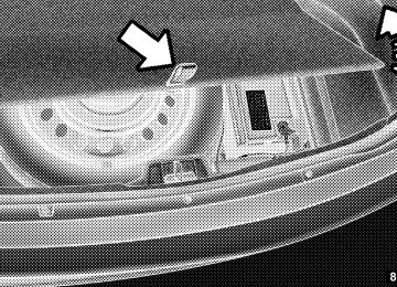
Emergency Fuel Filler Door Release If you are unable to open the fuel filler door, use the fuel filler door emergency release. 1. Open the trunk. 2. Remove the access cover (located on the left side inner trim panel).
Access Cover
3. Pull the release cable.
Release Cable
VEHICLE LOADING The load carrying capacity of your vehicle is shown on the “Vehicle Certification Label.” This information should be used for passenger and luggage loading as indicated.
STARTING AND OPERATING 431
Do not exceed the specified Gross Vehicle Weight Rating (GVWR) or the Gross Axle Weight Rating (GAWR). Vehicle Certification Label Your vehicle has a Vehicle Certification Label affixed to the rear of the driver’s door. The label contains the following information: • Name of manufacturer • Month and year of manufacture • Gross Vehicle Weight Rating (GVWR) • Gross Axle Weight Rating (GAWR) front • Gross Axle Weight Rating (GAWR) rear • Vehicle Identification Number (VIN) • Type of Vehicle • Month Day and Hour of Manufacture (MDH)432 STARTING AND OPERATING The bar code allows a computer scanner to read the VIN. Gross Vehicle Weight Rating (GVWR) The GVWR is the total allowable weight of your vehicle. This includes driver, passengers, and cargo. The total load must be limited so that you do not exceed the GVWR. Gross Axle Weight Rating (GAWR) The GAWR is the maximum capacity of the front and rear axles. Distribute the load over the front and rear axles evenly. Make sure that you do not exceed either front or rear GAWR.
WARNING!
Because the front wheels steer the vehicle, it is important that you do not exceed the maximum front or rear GAWR. A dangerous driving condition can result if either rating is exceeded. You could lose control of the vehicle and have a collision.
Overloading The load carrying components (axle, springs, tires, wheels, etc.) of your vehicle will provide satisfactory service as long as you do not exceed the GVWR and the front and rear GAWR. The best way to figure out the total weight of your vehicle is to weigh it when it is fully loaded and ready for operation. Weigh it on a commercial scale to ensure that it is not over the GVWR. Figure out the weight on the front and rear of the vehicle separately. It is important that you distribute the load evenly over the front and rear axles. Overloading can cause potential safety hazards and shorten useful service life. Heavier axles or suspension components do not necessarily increase the vehicle’s GVWR.
Loading To load your vehicle properly, first figure out its empty weight, axle-by-axle and side-by-side. Store heavier items down low and be sure you distribute their weight as evenly as possible. Stow all loose items securely before driving. If weighing the loaded vehicle shows that you have exceeded either GAWR, but the total load is within the specified GVWR, you must redistribute the weight. Improper weight distribution can have an adverse effect on the way your vehicle steers and handles and the way the brakes operate. NOTE: • Refer to the “Vehicle Certification Label” affixed to the rear of the driver’s door for your vehicle’s GVWR and GAWRs. • Refer to the “Tire Placard” for your vehicle’s proper
tire pressure.
STARTING AND OPERATING 433
TRAILER TOWING In this section, you will find safety tips and information on limits to the type of towing you can reasonably do with your vehicle. Before towing a trailer, carefully review this information to tow your load as efficiently and safely as possible. To maintain warranty coverage, follow the requirements and recommendations in this manual concerning ve- hicles used for trailer towing. Common Towing Definitions The following trailer towing related definitions will assist you in understanding the following information: Gross Vehicle Weight Rating (GVWR) The GVWR is the total allowable weight of your vehicle. This includes driver, passengers, cargo, and tongue weight. The total load must be limited so that you do not exceed the GVWR. Refer to “Vehicle Loading/Vehicle Certification Label” in “Starting and Operating” for further information.
434 STARTING AND OPERATING Gross Trailer Weight (GTW) The GTW is the weight of the trailer plus the weight of all cargo, consumables, and equipment (permanent or tem- porary) loaded in or on the trailer in its ⬙loaded and ready for operation⬙ condition. The recommended way to measure GTW is to put your fully loaded trailer on a vehicle scale. The entire weight of the trailer must be supported by the scale. Gross Combination Weight Rating (GCWR) The GCWR is the total permissible weight of your vehicle and trailer when weighed in combination. NOTE: The GCWR rating includes a 150 lbs (68 kg) allowance for the presence of a driver. Gross Axle Weight Rating (GAWR) The GAWR is the maximum capacity of the front and rear axles. Distribute the load over the front and rear axles evenly. Make sure that you do not exceed either front or
rear GAWR. Refer to “Vehicle Loading/Vehicle Certifica- tion Label” in “Starting and Operating” for further information.
WARNING!
It is important that you do not exceed the maximum front or rear GAWR. A dangerous driving condition can result if either rating is exceeded. You could lose control of the vehicle and have a collision.
Tongue Weight (TW) The tongue weight is the downward force exerted on the hitch ball by the trailer. In most cases, it should not be less than 10% or more than 15% of the trailer load. You must consider this as part of the load on your vehicle. Frontal Area The frontal area is the maximum height multiplied by the maximum width of the front of a trailer.
Trailer Sway Control The trailer sway control is a telescoping link that can be installed between the hitch receiver and the trailer tongue that typically provides adjustable friction associated with the telescoping motion to dampen any unwanted trailer swaying motions while traveling. Weight-Carrying Hitch A weight-carrying hitch supports the trailer tongue weight, just as if it were luggage located at a hitch ball or some other connecting point of the vehicle. These kinds of hitches are the most popular on the market today and they are commonly used to tow small- and medium- sized trailers. Weight-Distributing Hitch A weight-distributing system works by applying lever- age through spring (load) bars. They are typically used for heavier loads to distribute trailer tongue weight to the tow vehicle’s front axle and the trailer axle(s). When used
STARTING AND OPERATING 435
in accordance with the manufacturer’s directions, it pro- vides for a more level ride, offering more consistent steering and brake control thereby enhancing towing safety. The addition of a friction / hydraulic sway control also dampens sway caused by traffic and crosswinds and contributes positively to tow vehicle and trailer stability. Trailer sway control and a weight distributing (load equalizing) hitch are recommended for heavier Tongue Weights (TW) and may be required depending on vehicle and trailer configuration / loading to comply with Gross Axle Weight Rating (GAWR) requirements.WARNING!
• An improperly adjusted weight distributing hitch system may reduce handling, stability, braking performance, and could result in a collision.
(Continued)
436 STARTING AND OPERATING
WARNING! (Continued)
• Weight distributing systems may not be compatible with surge brake couplers. Consult with your hitch and trailer manufacturer or a reputable recreational vehicle dealer for additional information.
Trailer Hitch Classification Your vehicle may be factory equipped for safe towing of trailers weighing over 2,000 lbs (907 kg) with the optional Trailer Tow Prep Package. See your authorized dealer for package content. The following chart provides the industry standard for the maximum trailer weight a given trailer hitch class can tow and should be used to assist you in selecting the correct trailer hitch for your intended towing condition. Refer to the “Trailer Towing Weights (Maximum Trailer Weight Ratings)” chart for the Maximum GTW towable for your given drivetrain.
Trailer Hitch Classification Definitions
Class
Max. Trailer Hitch Indus-
try Standards
2,000 lbs (907 kg) 3,500 lbs (1 587 kg) 5,000 lbs (2 268 kg) 10,000 lbs (4 540 kg)
Class I - Light Duty Class II - Medium Duty Class III - Heavy Duty Class IV - Extra Heavy Duty Refer to the “Trailer Towing Weights (Maximum Trailer Weight Ratings)” chart for the Maximum Gross Trailer Weight (GTW) towable for your given drivetrain. All trailer hitches should be professionally installed on your vehicle.
Trailer Towing Weights (Maximum Trailer Weight Ratings) The following chart provides the maximum trailer weight ratings towable for your given drivetrain.
STARTING AND OPERATING 437
Engine/Transmission
Frontal Area
22 sq ft (2.04 sq m) 32 sq ft (2.97 sq m)
3.6L Automatic 5.7L Automatic Refer to local laws for maximum trailer towing speeds NOTE: The trailer tongue weight must be considered as part of the combined weight of occupants and cargo, and it should never exceed the weight referenced on the “Tire and Loading Information” placard. Re- fer to “Tire Safety Information” in “Starting and Operating” for further information.
100 lbs (45 kg) 100 lbs (45 kg)
Max. GTW
(Gross Trailer Wt.) 1,000 lbs (454 kg) 1,000 lbs (454 kg)
Max. Tongue Wt.
(See Note)
438 STARTING AND OPERATING Trailer And Tongue Weight Always load a trailer with 60% to 65% of the weight in the front of the trailer. This places 10% to 15% of the Gross Trailer Weight (GTW) on the tow hitch of your vehicle. Loads balanced over the wheels or heavier in the rear can cause the trailer to sway severely side to side which will cause loss of control of the vehicle and trailer. Failure to load trailers heavier in front is the cause of many trailer collisions. Never exceed the maximum tongue weight stamped on your bumper or trailer hitch.
Consider the following items when computing the weight on the rear axle of the vehicle: • The tongue weight of the trailer. • The weight of any other type of cargo or equipment • The weight of the driver and all passengers.
put in or on your vehicle.
NOTE: Remember that everything put into or on the trailer adds to the load on your vehicle. Also, additional factory-installed options or dealer-installed options must be considered as part of the total load on your vehicle. Refer to the “Tire and Loading Information” placard for the maximum combined weight of occupants and cargo for your vehicle. Towing Requirements To promote proper break-in of your new vehicle drive- train components the following guidelines are recom- mended:
CAUTION!
• Do not tow a trailer at all during the first 500 miles (805 km) the new vehicle is driven. The engine, axle or other parts could be damaged.
(Continued)
STARTING AND OPERATING 439
CAUTION! (Continued)
• Then, during the first 500 miles (805 km) that a trailer is towed, do not drive over 50 mph (80 km/h) and do not make starts at full throttle. This helps the engine and other parts of the vehicle wear in at the heavier loads.
WARNING!
Improper towing can lead to an injury collision. Follow these guidelines to make your trailer towing as safe as possible: • Make certain that the load is secured in the trailer and it will not shift during travel. When trailering cargo that is not fully secured, dynamic load shifts can occur that may be difficult for the driver to control. You could lose control of your vehicle and have a collision.
(Continued)
440 STARTING AND OPERATING
WARNING! (Continued)
• When hauling cargo or towing a trailer, do not overload your vehicle or trailer. Overloading can cause a loss of control, poor performance, or dam- age to brakes, axle, engine, transmission, steering, suspension, chassis structure, or tires. • Safety chains must always be used between your vehicle and trailer. Always connect the chains to the frame or hook retainers of the vehicle hitch. Cross the chains under the trailer tongue and allow enough slack for turning corners. • Vehicles with trailers should not be parked on a grade. When parking, apply the parking brake on the tow vehicle. Put the tow vehicle automatic transmission in PARK. Always, block or ⴖchockⴖ the trailer wheels.
• GCWR must not be exceeded.
(Continued)
WARNING! (Continued)
• Total weight must be distributed between the tow vehicle and the trailer such that the following four ratings are not exceeded: 1. Max loading as defined on the “Tire and Load- ing Information” placard. 2. GTW 3. GAWR 4. Tongue weight rating for the trailer hitch uti- lized. (This requirement may limit the ability to always achieve the 10% to 15% range of tongue weight as a percentage of total trailer weight.)
Towing Requirements – Tires − Do not attempt to tow a trailer while using a compact
spare tire.
− Proper tire inflation pressures are essential to the safe and satisfactory operation of your vehicle. Refer to “Tires – General Information” in “Starting and Oper- ating” for information on tire pressures and for proper tire inflation procedures.
− Check the trailer tires for proper tire inflation pres-
sures before trailer usage.
− Check for signs of tire wear or visible tire damage before towing a trailer. Refer to “Tires – General Information” in “Starting and Operating” for informa- tion on tread wear indicators and for the proper inspection procedure.
− When replacing tires, refer to “Tires – General Infor- mation” in “Starting and Operating” for information
STARTING AND OPERATING 441
on replacement tires and for the proper tire replace- ment procedures. Replacing tires with a higher load carrying capacity will not increase the vehicle’s GVWR and GAWR limits.Towing Requirements – Trailer Brakes − Do not interconnect the hydraulic brake system or vacuum system of your vehicle with that of the trailer. This could cause inadequate braking and possible personal injury.
− An electronically actuated trailer brake controller is required when towing a trailer with electronically actuated brakes. When towing a trailer equipped with a hydraulic surge actuated brake system, an electronic brake controller is not required.
− Trailer brakes are recommended for trailers over 1,000 lbs (454 kg) and required for trailers in excess of 2,000 lbs (907 kg).
442 STARTING AND OPERATING
CAUTION!
If the trailer weighs more than 1,000 lbs (454 kg) loaded, it should have its own brakes, and they should be of adequate capacity. Failure to do this could lead to accelerated brake lining wear, higher brake pedal effort, and longer stopping distances.
WARNING!
• Do not connect trailer brakes to your vehicle’s hydraulic brake lines. It can overload your brake system and cause it to fail. You might not have brakes when you need them and could have an collision.
(Continued)
WARNING! (Continued)
• Towing any trailer will increase your stopping distance. When towing, you should allow for ad- ditional space between your vehicle and the ve- hicle in front of you. Failure to do so could result in a collision.
Towing Requirements – Trailer Lights And Wiring Whenever you pull a trailer, regardless of the trailer size, stoplights and turn signals on the trailer are required for motoring safety. The Trailer Tow Package may include a four and seven- pin wiring harness. Use a factory approved trailer har- ness and connector. NOTE: Do not cut or splice wiring into the vehicles wiring harness.
The wiring harness is not installed when leaving the factory; it must be done by the dealer or customer. Refer to the following illustrations.
STARTING AND OPERATING 443
1 — Battery 2 — Backup Lamps 3 — Right Stop/Turn 4 — Electric Brakes
Seven-Pin Connector 5 — Ground 6 — Left Stop/Turn 7 — Running Lamps
1 — Female Pins 2 — Male Pin 3 — Ground
Four-Pin Connector 4 — Park 5 — Left Stop/Turn 6 — Right Stop/Turn
444 STARTING AND OPERATING Towing Tips Before setting out on a trip, practice turning, stopping, and backing up the trailer in an area located away from heavy traffic. Automatic Transmission The DRIVE range can be selected when towing. How- ever, if frequent shifting occurs while in this range, select a lower gear range using the AutoStick威 shift control (if equipped). NOTE: Selecting a lower gear range while operating the vehicle under heavy operating conditions will improve performance and extend transmission life by reducing excessive shifting and heat buildup. This action will also provide better engine braking. If you REGULARLY tow a trailer for more than 45 min- utes of continuous operation, then change the automatic transmission fluid and filter according to the interval
specified for “police, taxi, fleet, or frequent trailer tow- ing.” Refer to “Maintenance Schedule” for the proper maintenance intervals. Electronic Speed Control – If Equipped − Do not use in hilly terrain or with heavy loads. − When using the speed control, if you experience speed drops greater than 10 mph (16 km/h), disengage until you can get back to cruising speed.
− Use speed control in flat terrain and with light loads to
maximize fuel efficiency. AutoStick威 – If Equipped − By using the AutoStick威 mode and selecting a specific gear range, frequent shifting can be avoided. Select the highest gear range that allows for adequate perfor- mance and avoids frequent downshifts.
− Extended driving at high RPM should be avoided to prevent excess heat generation. A reduction in vehicle speed may be required to avoid extended driving at high RPM. Return to a higher gear range or vehicle speed when road conditions and RPM level allows.
Cooling System To reduce potential for engine and transmission over- heating, take the following actions: − City Driving When stopped for short periods of time, shift the trans- mission into NEUTRAL and increase engine idle speed. − Highway Driving Reduce speed. − Air Conditioning Turn off temporarily.
STARTING AND OPERATING 445
RECREATIONAL TOWING (BEHIND MOTORHOME, ETC.)
Two-Wheel Drive and All-Wheel Drive Recreational towing (with all four wheels on the ground, or using a tow dolly) is NOT ALLOWED. The only acceptable method for towing this vehicle (behind an- other vehicle) is on a vehicle trailer with all four wheels OFF the ground.
CAUTION!
Towing this vehicle in violation of the above require- ments can cause severe transmission and/or transfer case damage. Such damage is not covered by the New Vehicle Limited Warranty.
WHAT TO DO IN EMERGENCIES
CONTENTS
䡵 Hazard Warning Flashers . . . . . . . . . . . . . . . . 448
䡵 If Your Engine Overheats . . . . . . . . . . . . . . . . 448
䡵 Jacking And Tire Changing . . . . . . . . . . . . . . . 449
▫ Jack Location/Spare Tire Stowage . . . . . . . . 450
▫ Preparations For Jacking . . . . . . . . . . . . . . . 452
▫ Jacking And Changing A Tire . . . . . . . . . . . . 453
▫ Road Tire Installation . . . . . . . . . . . . . . . . . 458
䡵 Jump-Starting Procedures . . . . . . . . . . . . . . . . 458
▫ Preparations For Jump-Start . . . . . . . . . . . . . 459▫ Jump-Starting Procedure . . . . . . . . . . . . . . . 460
䡵 Freeing A Stuck Vehicle . . . . . . . . . . . . . . . . . 462
䡵 Shift Lever Override —5 Speed Transmission . . . . . . . . . . . . . . . . . . . 464
䡵 Manual Park Release —
8 Speed Transmission (3.6L Engine) . . . . . . . . . 465
䡵 Towing A Disabled Vehicle . . . . . . . . . . . . . . . 467
▫ Without The Ignition Key Fob . . . . . . . . . . . 469448 WHAT TO DO IN EMERGENCIES HAZARD WARNING FLASHERS The Hazard Warning flasher switch is located in the center of the instrument panel between the center air outlets.
Press the switch to turn on the Hazard Warning flashers. When the switch is activated, all direc- tional turn signals will flash on and off to warn oncoming traffic of an emergency. Press the switch a second time to turn off the Hazard Warning flashers. This is an emergency warning system and it should not be used when the vehicle is in motion. Use it when your vehicle is disabled and it is creating a safety hazard for other motorists. When you must leave the vehicle to seek assistance, the Hazard Warning flashers will continue to operate even though the ignition is placed in the OFF position. NOTE: With extended use the Hazard Warning flashers may wear down your battery.
IF YOUR ENGINE OVERHEATS In any of the following situations, you can reduce the potential for overheating by taking the appropriate action. • On the highways — slow down. • In city traffic — while stopped, place the transmission in NEUTRAL, but do not increase the engine idle speed.
NOTE: There are steps that you can take to slow down an impending overheat condition: • If your air conditioner (A/C) is on, turn it off. The A/C system adds heat to the engine cooling system and turning the A/C off can help remove this heat. • You can also turn the temperature control to maximum heat, the mode control to floor and the blower control to high. This allows the heater core to act as a supplement to the radiator and aids in removing heat from the engine cooling system.
CAUTION!
Driving with a hot cooling system could damage your vehicle. If the temperature gauge reads “H,” pull over and stop the vehicle. Idle the vehicle with the air conditioner turned off until the pointer drops back into the normal range. If the pointer remains on the “H,” turn the engine off immediately and call for service.
WARNING!
You or others can be badly burned by hot engine coolant (antifreeze) or steam from your radiator. If you see or hear steam coming from under the hood, do not open the hood until the radiator has had time to cool. Never try to open a cooling system pressure cap when the radiator or coolant bottle is hot.
JACKING AND TIRE CHANGING
WHAT TO DO IN EMERGENCIES 449
WARNING!
• Do not attempt to change a tire on the side of the vehicle close to moving traffic. Pull far enough off the road to avoid the danger of being hit when operating the jack or changing the wheel. • Being under a jacked-up vehicle is dangerous. The vehicle could slip off the jack and fall on you. You could be crushed. Never put any part of your body under a vehicle that is on a jack. If you need to get under a raised vehicle, take it to a service center where it can be raised on a lift. • Never start or run the engine while the vehicle is
on a jack.
(Continued)
450 WHAT TO DO IN EMERGENCIES
WARNING! (Continued)
• The jack is designed to be used as a tool for changing tires only. The jack should not be used to lift the vehicle for service purposes. The vehicle should be jacked on a firm level surface only. Avoid ice or slippery areas.
Jack Location/Spare Tire Stowage
The jack and spare tire are both stowed under an access cover in the trunk. Follow these steps to access the jack and spare tire. NOTE: The spare tire must be removed in order to access the jack. 1. Open the trunk.
2. Lift the access cover using the pull strap.
Opening The Access Panel
3. Remove the fastener securing the spare tire.
WHAT TO DO IN EMERGENCIES 451
Spare Tire Fastener
4. Remove the spare tire. 5. Remove the fastener securing the jack.
Jack Fastener
6. Remove the scissors jack and lug wrench from the spare wheel as an assembly. Turn the jack screw to the left to loosen the lug wrench, and remove the wrench from the jack assembly.
452 WHAT TO DO IN EMERGENCIES
WARNING!
• A loose tire or jack thrown forward in a collision or hard stop could endanger the occupants of the vehicle. Always stow the jack parts and the spare tire in the places provided. • Have the deflated (flat) tire repaired or replaced
immediately.
Preparations For Jacking
1. Park the vehicle on a firm, level surface as far from the edge of the roadway as possible. Avoid icy or slippery areas.
WARNING!
Do not attempt to change a tire on the side of the vehicle close to moving traffic, pull far enough off the road to avoid being hit when operating the jack or changing the wheel.
2. Turn on the Hazard Warning flasher. 3. Set the parking brake. 4. Place the shift lever into PARK. 5. Turn OFF the ignition.
6. Block the front and rear of the wheel diagonally opposite of the jack- ing position. For example, if changing the right front tire, block the left rear wheel.
NOTE: Passengers should not remain in the vehicle when the vehicle is being jacked.
Jacking And Changing A Tire
WARNING!
Carefully follow these tire changing warnings to help prevent personal injury or damage to your vehicle: • Always park on a firm, level surface as far from