- Download PDF Manual
-
Brake Wear Your vehicle has four-wheel disc brakes. Disc brake pads have built-in wear indicators that make a high-pitched warning sound when the brake pads are worn and new pads are needed. The sound may come and go or be heard all the time your vehicle is moving, except when you are pushing on the brake pedal firmly.
{CAUTION:
The brake wear warning sound means that soon your brakes will not work well. That could lead to an accident. When you hear the brake wear warning sound, have your vehicle serviced.
Notice: Continuing to drive with worn-out brake pads could result in costly brake repair. Some driving conditions or climates may cause a brake squeal when the brakes are first applied or lightly applied. This does not mean something is wrong with your brakes. Properly torqued wheel nuts are necessary to help prevent brake pulsation. When tires are rotated, inspect brake pads for wear and evenly tighten wheel nuts in the proper sequence to GM torque specifications. Brake linings should always be replaced as complete axle sets. Brake Pedal Travel See your dealer if the brake pedal does not return to normal height, or if there is a rapid increase in pedal travel. This could be a sign of brake trouble.
5-35
Warning: Battery posts, terminals, and related accessories contain lead and lead compounds, chemicals known to the State of California to cause cancer and reproductive harm. Wash hands after handling. Vehicle Storage If you are not going to drive your vehicle for 25 days or more, remove the black, negative (−) cable from the battery. This will help keep your battery from running down.
{CAUTION:
Batteries have acid that can burn you and gas that can explode. You can be badly hurt if you are not careful. See Jump Starting on page 5-37 for tips on working around a battery without getting hurt.
Brake Adjustment Every time you make a brake stop, your disc brakes adjust for wear. Replacing Brake System Parts The braking system on a vehicle is complex. Its many parts have to be of top quality and work well together if the vehicle is to have really good braking. Your vehicle was designed and tested with top-quality GM brake parts. When you replace parts of your braking system — for example, when your brake linings wear down and you need new ones put in — be sure you get new approved GM replacement parts. If you do not, your brakes may no longer work properly. For example, if someone puts in brake linings that are wrong for your vehicle, the balance between your front and rear brakes can change — for the worse. The braking performance you have come to expect can change in many other ways if someone puts in the wrong replacement brake parts.
Battery Your vehicle has a maintenance free battery. When it is time for a new battery, get one that has the replacement number shown on the original battery’s label. We recommend an ACDelco® replacement battery. The battery is located under the rear of the vehicle.
5-36
Jump Starting If your battery has run down, you may want to use another vehicle and some jumper cables to start your vehicle. Be sure to use the following steps to do it safely.
{CAUTION:
Batteries can hurt you. They can be dangerous because:
(cid:127) They contain acid that can burn you. (cid:127) They contain gas that can explode
(cid:127) They contain enough electricity to
or ignite.
burn you.
If you do not follow these steps exactly, some or all of these things can hurt you.
Ignoring these steps could result in costly
Notice: damage to your vehicle that would not be covered by your warranty. Trying to start your vehicle by pushing or pulling it will not work, and it could damage your vehicle. 1. Check the other vehicle. It must have a 12-volt
battery with a negative ground system.
If the other vehicle’s system is not a 12-volt
Notice: system with a negative ground, both vehicles can be damaged. Only use vehicles with 12-volt systems with negative grounds to jump start your vehicle. 2. Get the vehicles close enough so the jumper cables can reach, but be sure the vehicles are not touching each other. If they are, it could cause a ground connection you do not want. You would not be able to start your vehicle and the bad grounding could damage the electrical systems. To avoid the possibility of the vehicles rolling, set the parking brake firmly on both vehicles involved in the jump start procedure. Put an automatic transmission in PARK (P) or a manual transmission in NEUTRAL before setting the parking brake.
If you leave your radio or other accessories
Notice: on during the jump starting procedure, they could be damaged. The repairs would not be covered by your warranty. Always turn off your radio and other accessories when jump starting your vehicle. 3. Turn off the ignition on both vehicles. Unplug
unnecessary accessories plugged into the cigarette lighter or the accessory power outlets. Turn off the radio and all lamps that are not needed. This will avoid sparks and help save both batteries. And it could save the radio!
5-37
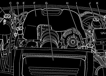
4. Open the hoods and locate the positive (+) and
negative (−) terminal locations on the other vehicle. Your vehicle has a remote positive (+) jump starting terminal and a remote negative (−) jump starting terminal. You should always use these remote terminals instead of the terminals on the battery.
The remote positive (+) terminal is located inside a red cover in the engine compartment on the passenger’s side of the vehicle. See item A in the Engine Compartment Overview on page 5-12.
Press inward on the tabs located on the outboard sides of the remote positive (+) terminal cover and pull outward to access the terminal.
Notice: Jump starting your vehicle’s battery using the engine compartment fuse block battery posts can damage your vehicle. See item K in the Engine Compartment Overview on page 5-12. Always use the remote positive terminal and remote negative terminal to jump start your vehicle’s battery. See items A and H in the Engine Compartment Overview on page 5-12
for location.5-38
The remote negative (−) terminal is located near the power steering fluid reservoir. It is marked GND (−). See item H in the Engine Compartment Overview on page 5-12 for more information on location.
You will not see the battery of your vehicle under the hood. It is located on the rear underside of the vehicle. You will not need to access the battery for jump starting. The remote positive (+) terminal is for that purpose.
{CAUTION:
An electric fan can start up even when the engine is not running and can injure you. Keep hands, clothing and tools away from any underhood electric fan.
{CAUTION:
Using a match near a battery can cause battery gas to explode. People have been hurt doing this, and some have been blinded. Use a flashlight if you need more light. Be sure the battery has enough water. You do not need to add water to the battery installed in your new vehicle. But if a battery has filler caps, be sure the right amount of fluid is there. If it is low, add water to take care of that first. If you do not, explosive gas could be present. Battery fluid contains acid that can burn you. Do not get it on you. If you accidentally get it in your eyes or on your skin, flush the place with water and get medical help immediately.
{CAUTION:
Fans or other moving engine parts can injure you badly. Keep your hands away from moving parts once the engine is running.
5-39
5. Check that the jumper cables do not have loose or
missing insulation. If they do, you could get a shock. The vehicles could be damaged too. Before you connect the cables, here are some basic things you should know. Positive (+) will go to positive (+) or to a remote positive (+) terminal if the vehicle has one. Negative (−) will go to a heavy, unpainted metal engine part or to a remote negative (−) terminal if the vehicle has one. Do not connect positive (+) to negative (−) or you will get a short that would damage the battery and maybe other parts too. And do not connect the negative (−) cable to the negative (−) terminal on the dead battery because this can cause sparks.
6. Connect the red positive (+) cable to the positive (+)
terminal of the dead battery. Use a remote positive (+) terminal if the vehicle has one.
7. Do not let the other end touch metal. Connect it to the positive (+) terminal of the good battery. Use a remote positive (+) terminal if the vehicle has one.
8. Now connect the black negative (−) cable to the negative (−) terminal of the good battery. Use a remote negative (−) terminal if the vehicle has one. Do not let the other end of the cable touch anything until the next step. The other end of the negative (−) cable does not go to the dead battery. It goes to a heavy, unpainted metal engine part or to a remote negative (−) terminal on the vehicle with the dead battery.
9. Connect the other end of the negative (−) cable at
least 18 inches (45 cm) away from the dead battery, but not near engine parts that move. The electrical connection is just as good there, and the chance of sparks getting back to the battery is much less. Use a remote negative (−) terminal if the vehicle has one. Your vehicle’s remote negative (−) terminal is marked GND (−).
10. Now start the vehicle with the good battery and run
the engine for a while.
11. Try to start the vehicle that had the dead battery.
If it will not start after a few tries, it probably needs service.
5-40
If the jumper cables are connected or
Notice: removed in the wrong order, electrical shorting may occur and damage the vehicle. The repairs would not be covered by your warranty. Always connect and remove the jumper cables in the correct order, making sure that the cables do not touch each other or other metal.
To disconnect the jumper cables from both vehicles, do the following: 1. Disconnect the black negative (−) cable from the
vehicle that had the dead battery.
2. Disconnect the black negative (−) cable from the
vehicle with the good battery.
3. Disconnect the red positive (+) cable from the
vehicle with the good battery.
4. Disconnect the red positive (+) cable from the
other vehicle.
5. Return the remote positive (+) terminal cover to its
original position.
Jumper Cable Removal
A. Dead Battery or Remote Positive (+) Terminal B. Good Battery or Remote Positive (+) and Remote
Negative (−) Terminals
C. Heavy, Unpainted Metal Engine Part or Remote
Negative (−) Terminal (GND)
5-41
If your vehicle has a manual transmission, you will have one of the following rear axles.
Rear Axle When to Check and Change Lubricant It is not necessary to regularly check the rear axle fluid unless there is a leak in the system or you hear an unusual noise. A fluid loss in the system indicates that you have a problem. Have the system inspected and repaired. How to Check Lubricant
Manual Transmission
Automatic Transmission
5-42
Headlamp Aiming If your vehicle is damaged in an accident, the headlamp aim may be affected. If you believe your headlamps need to be re-aimed, we recommend that you take your vehicle to the dealer for service. However, it is possible for you to re-aim your headlamps by following the procedure in the service manual for your vehicle. See Service Publications Ordering Information on page 7-14 for more information. Bulb Replacement For the proper type of replacement bulbs, see Replacement Bulbs on page 5-48. For any bulb changing procedure not listed in this section, contact your dealer.
5-43
Manual Transmission
To get an accurate reading, the vehicle should be on a level surface. The proper level is from 0 to 3/8 inch (0 to 10 mm) below the bottom of the filler plug hole. If the level is below the bottom of the filler plug hole, located on the rear axle, you’ll need to add some lubricant. Add enough lubricant to raise the level to the bottom of the filler plug hole. What to Use See Recommended Fluids and Lubricants on page 6-12
for the type of fluid to use.Halogen Bulbs
{CAUTION:
Halogen bulbs have pressurized gas inside and can burst if you drop or scratch the bulb. You or others could be injured. Be sure to read and follow the instructions on the bulb package.
Headlamps To replace the headlamp bulbs, do the following: 1. Turn the front wheels as far as they will go in the
opposite direction of the bulb that is being changed.
2. Reach underneath the vehicle and locate the
headlamp door. Remove the fastener retaining the door.
5-44
3. Turn the bulb socket counterclockwise to remove it
from the headlamp assembly. There are separate sockets for the high and low-beam headlamps.
4. Pull the bulb socket out of the headlamp assembly.
5. Disconnect the bulb socket from the wiring harness
and replace the unit.
6. Reinstall the bulb socket back into the headlamp
assembly by turning it clockwise.
7. Reinstall the headlamp cover and tighten
the fastener.
Front Turn Signal, Sidemarker and Parking Lamps Front Turn and Parking Lamps To replace the front turn or parking lamp bulbs, do the following: 1. Open the hood. See Hood Release on page 5-11
for more information.
2. Locate the bar that runs across the front of the
vehicle and remove the two screws located near the front of the hood that hold the bar in place.
3. Release the tabs that attach the bar to
the headlamps.
5-45
4. Pull outward on the bar to remove it from
the vehicle.
5. Locate and release the tabs behind the grille that hold the lamp assembly in place. Unsnap the tabs and push forward to remove the lamp assembly. 6. Turn the bulb socket counterclockwise to access
the bulb.
7. Pull the old bulb out of the socket and push in a
new bulb.
8. Reverse the steps to reinstall the lamp assembly.
5-46
Sidemarker Lamps To replace a sidemarker bulb, do the following: 1. Reach underneath the vehicle to locate the
sidemarker bulb.
2. Turn the bulb socket counterclockwise to remove it. 3. Pull the old bulb out of the socket and push in a
new bulb.
4. Reverse steps to reinstall the bulb socket.
Taillamps, Turn Signal, and Stoplamps To replace a taillamp bulb, do the following: 1. Reach underneath the rear of the vehicle.
2. Find the bulb socket, twist counterclockwise, and
remove it from the lamp assembly.
3. Pull the old bulb out of the socket and push in a
new bulb.
4. Reinstall the socket into the lamp assembly and
turn it clockwise to secure.
5-47
Back-Up Lamps To replace a back-up lamp bulb, do the following: 1. Reach underneath the vehicle near the license plate
and find the bulb socket.
2. Remove the socket from the lamp assembly by
locating and then squeezing the release tab while turning the socket counterclockwise.
5-48
3. Turn the bulb counterclockwise and then pull
outward to remove it from the socket.
4. Insert a new bulb into the socket by lining up the
notches on the bulb and turn it clockwise to secure it.
5. Reverse the steps to reinstall the lamp assembly on
the vehicle.
Replacement Bulbs
Exterior Lamp
Bulb Number
Back-Up Lamp Front Turn Signal/Parking Lamp Headlamps
High-Beam Low-Beam
Sidemarker Lamp Stoplamp, Taillamp and Turn Signal Lamp
2057
T209005HB3
H11
1943157
For replacement bulbs not listed here, contact your dealer.
Windshield Wiper Blade Replacement Windshield wiper blades should be inspected periodically for wear and cracking. See Scheduled Maintenance on page 6-4. Replacement blades come in different types and are removed in different ways. For proper type and length, see Normal Maintenance Replacement Parts on page 6-14. Allowing the wiper blade arm to touch the windshield when no wiper blade is installed could damage the windshield. Any damage that occurs would not be covered by your warranty. Do not allow the wiper blade arm to touch the windshield. 1. To remove the old wiper blades, lift the wiper arm
until it locks into a vertical position.
A. Blade Assembly B. Arm Assembly C. Locking Tab
D. Blade Pivot E. Hook Slot F. Arm Hook
2. Press down on the blade assembly pivot locking
tab. Pull down on the blade assembly to release it from the wiper arm hook.
3. Remove the insert from the blade assembly. The
insert has two notches at one end that are locked by bottom claws of the blade assembly. At the notched end, pull the insert from the blade assembly.
5-49
4. To install the new wiper insert, slide the insert (D),
notched end last, into the end with two blade claws (A). Slide the insert all the way through the blade claws at the opposite end (B). The plastic caps (C) will be forced off as the insert is fully inserted.
5. Be sure that the notches are locked by the bottom claws. Make sure that all other claws are properly locked on both sides of the insert slots.
5-50
A. Claw in Notch B. Correct Installation C. Incorrect Installation
6. Put the blade assembly pivot in the wiper arm hook. Pull up until the pivot locking tab locks in the hook slot.
7. Carefully lower the wiper arm and blade assembly
onto the windshield.
Tires Your new vehicle comes with high-quality tires made by a leading tire manufacturer. If you ever have questions about your tire warranty and where to obtain service, see your GM Warranty booklet for details. For additional information refer to the tire manufacturer’s booklet included with your vehicle’s Owner’s Manual.
{CAUTION:
(cid:127) Poorly maintained and improperly used
tires are dangerous.
(cid:127) Overloading your tires can cause
overheating as a result of too much friction. You could have an air-out and a serious accident. See Loading Your Vehicle on page 4-29.
CAUTION:
(Continued)
CAUTION:
(Continued)
(cid:127) Underinflated tires pose the same danger as overloaded tires. The resulting accident could cause serious injury. Check all tires frequently to maintain the recommended pressure. Tire pressure should be checked when your tires are cold.
(cid:127) Overinflated tires are more likely to be cut, punctured, or broken by a sudden impact — such as when you hit a pothole. Keep tires at the recommended pressure.
(cid:127) Worn, old tires can cause accidents. If
your tread is badly worn, or if your tires have been damaged, replace them.
See Inflation - Tire Pressure on page 5-57
for inflation pressure adjustment for high speed driving.5-51
Winter Tires If you expect to drive on snow or ice covered roads often, you may want to get winter tires for your vehicle. All season tires provide good overall performance on most surfaces but they may not offer the traction you would like or the same level of performance as winter tires on snow or ice covered roads. See your dealer for details regarding winter tire availability and proper tire selection. Also, see Buying New Tires on page 5-60
If you choose to use winter tires: • Use tires of the same brand and tread type on allfour wheel positions.
• Use only radial ply tires of the same size, load
range, and speed rating as the original equipment tires.
Winter tires with the same speed rating as your original equipment tires may not be available for H, V, W and ZR speed rated tires. If you choose winter tires with a lower speed rating, never exceed the tire’s maximum speed capability.
5-52
Tire Sidewall Labeling Useful information about a tire is molded into the sidewall. The following illustration is an example of a typical P-Metric tire sidewall.
(A) Tire Size: The tire size code is a combination of letters and numbers used to define a particular tire’s width, height, aspect ratio, construction type, and service description. See the Tire Size illustration later in this section for more detail.
(B) TPC Spec (Tire Performance Criteria Specification): Original equipment tires designed to GM’s specific tire performance criteria have a TPC specification code molded onto the sidewall. GM’s TPC specifications meet or exceed all federal safety guidelines.
(C) DOT (Department of Transportation): The Department of Transportation (DOT) code indicates that the tire is in compliance with the U.S. Department of Transportation Motor Vehicle Safety Standards.
(D) Tire Identification Number (TIN): The letters and numbers following the DOT code are the Tire Identification Number (TIN). The TIN shows the manufacturer and plant code, tire size, and date the tire was manufactured. The TIN is molded onto both sides of the tire, although only one side may have the date of manufacture.
(E) Tire Ply Material: The type of cord and number of plies in the sidewall and under the tread.
(F) Uniform Tire Quality Grading (UTQG): Tire manufacturers are required to grade tires based on three performance factors: treadwear, traction, and temperature resistance. For more information, see Uniform Tire Quality Grading on page 5-62.
(G) Maximum Cold Inflation Load Limit: Maximum load that can be carried and the maximum pressure needed to support that load. For information on recommended tire pressure see Inflation - Tire Pressure on page 5-57 and Loading Your Vehicle on page 4-29.
5-53
Tire Size The following illustration shows, an example of, a typical passenger car tire size.
(A) Passenger (P-Metric) Tire: The United States version of a metric tire sizing system. The letter P as the first character in the tire size means a passenger vehicle tire engineered to standards set by the U.S. Tire and Rim Association.
(B) Tire Width: The three-digit number indicates the tire section width in millimeters from sidewall to sidewall.
(C) Aspect Ratio: A two-digit number that indicates the tire height-to-width measurements. For example, if the tire size aspect ratio is 75, as shown in item C, of the illustration, it would mean that the tire’s sidewall is 75 percent as high as it is wide.
5-54
(D) Construction Code: A letter code is used to indicate the type of ply construction in the tire. The letter R means radial ply construction; the letter D means diagonal or bias ply construction; and the letter B means belted-bias ply construction.
(E) Rim Diameter: Diameter of the wheel in inches.
(F) Service Description: The service description indicates the load range and speed rating of a tire. The load index can range from 1 to 279. Speed ratings range from A to Z.
Tire Terminology and Definitions
Air Pressure: The amount of air inside the tire pressing outward on each square inch of the tire. Air pressure is expressed in pounds per square inch (psi) or kilopascal (kPa).
Accessory Weight: This means the combined weight of optional accessories. Some examples of optional accessories are, automatic transmission, power steering, power brakes, power windows, power seats, and air conditioning.
Aspect Ratio: The relationship of a tire’s height to its width.
Belt: A rubber coated layer of cords that is located between the plies and the tread. Cords may be made from steel or other reinforcing materials.
Bead: The tire bead contains steel wires wrapped by steel cords that hold the tire onto the rim.
Bias Ply Tire: A pneumatic tire in which the plies are laid at alternate angles less than 90 degrees to the centerline of the tread.
Cold Inflation Pressure: The amount of air pressure in a tire, measured in pounds per square inch (psi) or kilopascals (kPa) before a tire has built up heat from driving. See Inflation - Tire Pressure on page 5-57.
Curb Weight: This means the weight of a motor vehicle with standard and optional equipment including the maximum capacity of fuel, oil and coolant, but without passengers and cargo.
DOT Markings: A code molded into the sidewall of a tire signifying that the tire is in compliance with the U.S. Department of Transportation (DOT) motor vehicle safety standards. The DOT code includes the Tire Identification Number (TIN), an alphanumeric designator which can also identify the tire manufacturer, production plant, brand and date of production.
GVWR: Gross Vehicle Weight Rating, see Loading Your Vehicle on page 4-29.
GAWR FRT: Gross Axle Weight Rating for the front axle, see Loading Your Vehicle on page 4-29.
GAWR RR: Gross Axle Weight Rating for the rear axle, see Loading Your Vehicle on page 4-29.
Intended Outboard Sidewall: The side of an asymmetrical tire, that must always face outward when mounted on a vehicle.
Kilopascal (kPa): The metric unit for air pressure.
Light Truck (LT-Metric) Tire: A tire used on light duty trucks and some multipurpose passenger vehicles.
Load Index: An assigned number ranging from 1 to 279 that corresponds to the load carrying capacity of a tire.
Maximum Inflation Pressure: The maximum air pressure to which a cold tire may be inflated. The maximum air pressure is molded onto the sidewall.
Maximum Load Rating: The load rating for a tire at the maximum permissible inflation pressure for that tire.
Maximum Loaded Vehicle Weight: The sum of curb weight; accessory weight; vehicle capacity weight; and production options weight.
Normal Occupant Weight: The number of occupants a vehicle is designed to seat multiplied by 150 lbs (68 kg). See Loading Your Vehicle on page 4-29.
5-55
Occupant Distribution: Designated seating positions.
Outward Facing Sidewall: The side of an asymmetrical tire that has a particular side that faces outward when mounted on a vehicle. The side of the tire that contains a whitewall, bears white lettering, or bears manufacturer, brand, and/or model name molding that is higher or deeper than the same moldings on the other sidewall of the tire.
Passenger (P-Metric) Tire: A tire used on passenger cars and some light duty trucks and multipurpose vehicles.
Recommended Inflation Pressure: Vehicle manufacturer’s recommended tire inflation pressure and shown on the tire placard. See Inflation - Tire Pressure on page 5-57 and Loading Your Vehicle on page 4-29.
Radial Ply Tire: A pneumatic tire in which the ply cords that extend to the beads are laid at 90 degrees to the centerline of the tread.
Rim: A metal support for a tire and upon which the tire beads are seated.
Sidewall: The portion of a tire between the tread and the bead.
Speed Rating: An alphanumeric code assigned to a tire indicating the maximum speed at which a tire can operate.
5-56
Traction: The friction between the tire and the road surface. The amount of grip provided. Tread: The portion of a tire that comes into contact with the road. Treadwear Indicators: Narrow bands, sometimes called wear bars, that show across the tread of a tire when only 1/16 inch (1.6 mm) of tread remains. See When It Is Time for New Tires on page 5-59. UTQGS (Uniform Tire Quality Grading Standards): A tire information system that provides consumers with ratings for a tire’s traction, temperature, and treadwear. Ratings are determined by tire manufacturers using government testing procedures. The ratings are molded into the sidewall of the tire. See Uniform Tire Quality Grading on page 5-62. Vehicle Capacity Weight: The number of designated seating positions multiplied by 150 lbs (68 kg) plus the rated cargo load. See Loading Your Vehicle on page 4-29. Vehicle Maximum Load on the Tire: Load on an individual tire due to curb weight, accessory weight, occupant weight, and cargo weight. Vehicle Placard: A label permanently attached to a vehicle showing the vehicle’s capacity weight and the original equipment tire size and recommended inflation pressure. See “Tire and Loading Information Label” under Loading Your Vehicle on page 4-29.
Inflation - Tire Pressure Tires need the correct amount of air pressure to operate effectively. Notice: Do not let anyone tell you that under-inflation or over-inflation is all right. It is not. If your tires do not have enough air (under-inflation), you can get the following:
Too much flexing Too much heat Tire overloading
(cid:127) Premature or irregular wear (cid:127) Poor handling (cid:127) Reduced fuel economy If your tires have too much air (over-inflation), you can get the following: (cid:127) Unusual wear (cid:127) Poor handling (cid:127) Rough ride (cid:127) Needless damage from road hazards
A Tire and Loading Information label is attached to the vehicle’s center pillar, below the driver’s door latch. This label lists your vehicle’s original equipment tires and shows the correct inflation pressures for your tires when they are cold. The recommended cold tire inflation pressure, shown on the label, is the minimum amount of air pressure needed to support your vehicle’s maximum load carrying capacity. For additional information regarding how much weight your vehicle can carry, and an example of the tire and loading information label, see Loading Your Vehicle on page 4-29. How you load your vehicle affects vehicle handling and ride comfort. Never load your vehicle with more weight than it was designed to carry. When to Check Check your tires once a month or more.
5-57
(cid:127) (cid:127) (cid:127) How to Check Use a good quality pocket-type gage to check tire pressure. You cannot tell if your tires are properly inflated simply by looking at them. Radial tires may look properly inflated even when they’re under-inflated. Check the tire’s inflation pressure when the tires are cold. Cold means your vehicle has been sitting for at least three hours or driven no more than 1 mile (1.6 km). Remove the valve cap from the tire valve stem. Press the tire gage firmly onto the valve to get a pressure measurement. If the cold tire inflation pressure matches the recommended pressure on the Tire and Loading Information label, no further adjustment is necessary. If the inflation pressure is low, add air until you reach the recommended amount. If you overfill the tire, release air by pushing on the metal stem in the center of the tire valve. Re-check the tire pressure with the tire gage. Be sure to put the valve caps back on the valve stems. They help prevent leaks by keeping out dirt and moisture.
High Speed Operation
{CAUTION:
Driving at high speeds, 100 mph (160 km/h) or higher, puts an additional strain on tires. Sustained high-speed driving causes excessive heat build up and can cause sudden tire failure. You could have a crash and you or others could be killed. Some high-speed rated tires require inflation pressure adjustment for high speed operation. When speed limits and road conditions are such that a vehicle can be driven at high speeds, make sure the tires are rated for high speed operation, in excellent condition, and set to the correct cold tire inflation pressure for the vehicle load.
5-58
If you will be driving your vehicle at speeds of 100 mph (160 km/h) or higher, where it is legal, set the cold inflation pressure to the maximum inflation pressure shown on the tire sidewall, or 35 psi (244 kPa), whichever is lower. See the example following. When you end this high-speed driving, return the tires to the cold inflation pressure shown on the Tire and Loading Information label. See Loading Your Vehicle on page 4-29. Example: You will find the maximum load and inflation pressure molded on the tire’s sidewall, in small letters, near the rim flange. It will read something like this: Maximum load 690 kg (1521 lbs) 300 kPa (44 psi) Max. Press. For this example, you would set the inflation pressure for high-speed driving at 35 psi (244 kPa) for the front and rear tires. Racing or other competitive driving may affect the warranty coverage of your vehicle. See your warranty booklet for more information.
Tire Inspection and Rotation The tires on your vehicle are different sizes front to rear. Due to this, your tires should not be rotated. Each tire and wheel should be used only in the position it is in. Check your tires and wheels regularly for unusual wear and damage. Also see, Scheduled Maintenance on page 6-4, When It Is Time for New Tires on page 5-59
and Wheel Replacement on page 5-64.When It Is Time for New Tires
One way to tell when it is time for new tires is to check the treadwear indicators, which will appear when your tires have only 1/16 inch (1.6 mm) or less of tread remaining. Some commercial truck tires may not have treadwear indicators.
5-59
You need a new tire if any of the following statements are true: • You can see the indicators at three or more places
around the tire.
• You can see cord or fabric showing through the
tire’s rubber.
• The tread or sidewall is cracked, cut or snagged
deep enough to show cord or fabric. • The tire has a bump, bulge, or split. • The tire has a puncture, cut, or other damage that
cannot be repaired well because of the size or location of the damage.
Buying New Tires GM has developed and matched specific tires for your vehicle. The original equipment tires installed on your vehicle, when it was new, were designed to meet General Motors Tire Performance Criteria Specification (TPC spec) system rating. If you need replacement tires, GM strongly recommends that you get tires with the same TPC Spec rating. This way, your vehicle will continue to have tires that are designed to give the same performance and vehicle safety, during normal use, as the original tires. GM’s exclusive TPC Spec system considers over a dozen critical specifications that impact the overall performance of your vehicle, including brake system performance, ride and handling, traction control, and tire pressure monitoring performance. GM’s TPC Spec number is molded onto the tire’s sidewall by the tire manufacturer. If the tires have an all-season tread design, the TPC spec number will be followed by an MS for mud and snow. See Tire Sidewall Labeling on page 5-52 for additional information.
5-60
Winter tires with the same speed rating as your original equipment tires may not be available for H, V, W, Y, and ZR speed rated tires. If you choose snow tires with a lower speed rating, never exceed the tire’s maximum speed capability.
{CAUTION:
Mixing tires could cause you to lose control while driving. If you mix tires of different sizes (other than those originally installed on your vehicle), brands, or types (radial and bias-belted tires), the vehicle may not handle properly, and you could have a crash. Using tires of different sizes (other than those originally installed on your vehicle), brands or types, may also cause damage to your vehicle. Be sure to use the correct size, brand, and type tires on all four wheels.
{CAUTION:
If you use bias-ply tires on your vehicle, the wheel rim flanges could develop cracks after many miles of driving. A tire and/or wheel could fail suddenly, causing a crash. Use only radial-ply tires with the wheels on your vehicle.
If you must replace your vehicle’s tires with those that do not have a TPC Spec number, make sure they are the same size, load range, speed rating, and construction type (radial and bias-belted tires) as your vehicle’s original tires. Your vehicle’s original equipment tires are listed on the Tire and Loading Information Label. This label is attached to the vehicle’s B-pillar. See Loading Your Vehicle on page 4-29 for more information about the Tire and Loading Information Label and its location on your vehicle.
5-61
Uniform Tire Quality Grading Quality grades can be found where applicable on the tire sidewall between tread shoulder and maximum section width. For example: Treadwear 200 Traction AA Temperature A The following information relates to the system developed by the United States National Highway Traffic Safety Administration, which grades tires by treadwear, traction and temperature performance. (This applies only to vehicles sold in the United States.) The grades are molded on the sidewalls of most passenger car tires. The Uniform Tire Quality Grading system does not apply to deep tread, winter-type snow tires, space-saver or temporary use spare tires, tires with nominal rim diameters of 10 to 12 inches (25 to 30 cm), or to some limited-production tires. While the tires available on General Motors passenger cars and light trucks may vary with respect to these grades, they must also conform to federal safety requirements and additional General Motors Tire Performance Criteria (TPC) standards.
Different Size Tires and Wheels If you add wheels or tires that are a different size than your original equipment wheels and tires, this may affect the way your vehicle performs, including its braking, ride and handling characteristics, stability and resistance to rollover. Additionally, if your vehicle has electronic systems such as, anti-lock brakes, traction control, and electronic stability control, the performance of these systems can be affected.
{CAUTION:
If you add different sized wheels, your vehicle may not provide an acceptable level of performance and safety if tires not recommended for those wheels are selected. You may increase the chance that you will crash and suffer serious injury. Only use GM specific wheel and tire systems developed for your vehicle, and have them properly installed by a GM certified technician.
See Buying New Tires on page 5-60 and Accessories and Modifications on page 5-3 for additional information.
5-62
Treadwear The treadwear grade is a comparative rating based on the wear rate of the tire when tested under controlled conditions on a specified government test course. For example, a tire graded 150 would wear one and a half (1.5) times as well on the government course as a tire graded 100. The relative performance of tires depends upon the actual conditions of their use, however, and may depart significantly from the norm due to variations in driving habits, service practices and differences in road characteristics and climate. Traction – AA, A, B, C The traction grades, from highest to lowest, are AA, A, B, and C. Those grades represent the tire’s ability to stop on wet pavement as measured under controlled conditions on specified government test surfaces of asphalt and concrete. A tire marked C may have poor traction performance. Warning: The traction grade assigned to this tire is based on straight-ahead braking traction tests, and does not include acceleration, cornering, hydroplaning, or peak traction characteristics. Temperature – A, B, C The temperature grades are A (the highest), B, and C, representing the tire’s resistance to the generation of heat and its ability to dissipate heat when tested under controlled conditions on a specified indoor
laboratory test wheel. Sustained high temperature can cause the material of the tire to degenerate and reduce tire life, and excessive temperature can lead to sudden tire failure. The grade C corresponds to a level of performance which all passenger car tires must meet under the Federal Motor Vehicle Safety Standard No. 109. Grades B and A represent higher levels of performance on the laboratory test wheel than the minimum required by law. Warning: The temperature grade for this tire is established for a tire that is properly inflated and not overloaded. Excessive speed, underinflation, or excessive loading, either separately or in combination, can cause heat buildup and possible tire failure.
Wheel Alignment and Tire Balance The tires and wheels on your vehicle were aligned and balanced carefully at the factory to give you the longest tire life and best overall performance. Adjustments to wheel alignment and tire balancing will not be necessary on a regular basis. However, if you notice unusual tire wear or your vehicle pulling to one side or the other, the alignment may need to be checked. If you notice your vehicle vibrating when driving on a smooth road, your tires and wheels may need to be rebalanced. See your dealer for proper diagnosis.
5-63
Wheel Replacement Replace any wheel that is bent, cracked, or badly rusted or corroded. If wheel nuts keep coming loose, the wheel, wheel bolts and wheel nuts should be replaced. If the wheel leaks air, replace it (except some aluminum wheels, which can sometimes be repaired). See your dealer if any of these conditions exist. Your dealer will know the kind of wheel you need. Each new wheel should have the same load-carrying capacity, diameter, width, offset and be mounted the same way as the one it replaces. If you need to replace any of your wheels, wheel bolts or wheel nuts, replace them only with new GM original equipment parts. This way, you will be sure to have the right wheel, wheel bolts and wheel nuts for your vehicle.
{CAUTION:
Using the wrong replacement wheels, wheel bolts, or wheel nuts on your vehicle can be dangerous. It could affect the braking and handling of your vehicle, make your tires lose air and make you lose control. You could have a collision in which you or others could be injured. Always use the correct wheel, wheel bolts and wheel nuts for replacement.
Notice: The wrong wheel can also cause problems with bearing life, brake cooling, speedometer or odometer calibration, headlamp aim, bumper height, vehicle ground clearance and tire clearance to the body and chassis.
5-64
{CAUTION:
{CAUTION:
Incorrect wheel nuts or improperly tightened wheel nuts can cause the wheel to become loose and even come off. This could lead to a crash. Be sure to use the correct wheel nuts. If you have to replace them, be sure to get new GM original equipment wheel nuts.
Improperly tightened wheel nuts can lead
Notice: to brake pulsation and rotor damage. To avoid expensive brake repairs, evenly tighten the wheel nuts in the proper sequence and to the proper torque specification.
Rust or dirt on a wheel, or on the parts to which it is fastened, can make wheel nuts become loose after a time. The wheel could come off and cause a crash. When you change a wheel, remove any rust or dirt from places where the wheel attaches to the vehicle. In an emergency, you can use a cloth or a paper towel to do this; but be sure to use a scraper or wire brush later, if you need to, to get all the rust or dirt off.
{CAUTION:
Never use oil or grease on studs or the threads of the wheel nuts. If you do, the wheel nuts might come loose and the wheel could fall off, causing a crash.
5-65
Used Replacement Wheels
Tire Chains
{CAUTION:
{CAUTION:
Putting a used wheel on your vehicle is dangerous. You cannot know how it has been used or how far it has been driven. It could fail suddenly and cause a crash. If you have to replace a wheel, use a new GM original equipment wheel.
Do not use tire chains. There is not enough clearance. Tire chains used on a vehicle without the proper amount of clearance can cause damage to the brakes, suspension or other vehicle parts. The area damaged by the tire chains could cause you to lose control of your vehicle and you or others may be injured in a crash. Use another type of traction device only if its manufacturer recommends it for use on your vehicle and tire size combination and road conditions. Follow that manufacturer’s instructions. To help avoid damage to your vehicle, drive slowly, re-adjust or remove the device if it is contacting your vehicle, and do not spin your wheels. If you do find traction devices that will fit, install them on the rear tires.
5-66
If a Tire Goes Flat Your vehicle has no spare tire, no tire changing equipment and no place to store a tire. It is unusual for a tire to blow out while you are driving, especially if you maintain your tires properly. See Tires on page 5-51. If air goes out of a tire, it’s much more likely to leak out slowly. But if you should ever have a blow out here are a few tips about what to expect and what to do: If a front tire fails, the flat tire will create a drag that pulls the vehicle toward that side. Take your foot off the accelerator pedal and grip the steering wheel firmly. Steer to maintain lane position, and then gently brake to a stop well out of the traffic lane. A rear blow out, particularly on a curve, acts much like a skid and may require the same correction you would use in a skid. In any rear blow out, remove your foot from the accelerator pedal. Get the vehicle under control by steering the way you want the vehicle to go. It may be very bumpy and noisy, but you can still steer. Gently brake to a stop, well off the road if possible.
If a tire goes flat, avoid further tire and wheel damage by driving slowly to a level place and stopping. Then do this: 1. Turn on the hazard warning flashers. 2. Park your vehicle. If your vehicle has an automatic
transmission, set the parking brake firmly and put the shift lever in PARK (P). See Shifting Into Park (P) on page 2-23 for additional information. If your vehicle has a manual transmission, move the shift lever to REVERSE (R) and set the parking brake firmly. See Parking Your Vehicle (Manual Transmission) on page 2-25 for additional information.
3. Turn off the engine. 4. Inspect the flat tire. If the tire has been separated from the wheel or has damaged sidewalls or large tears that allow rapid air loss, call a tire repair facility. See Roadside Assistance Program on page 7-6.
5-67
If the flat tire is due to a slow leak caused by a nail or other similar road hazard, the tire inflator kit may be used to repair the damaged tire temporarily. The kit uses a liquid tire sealant to seal small punctures in the tread area of the tire. The flat tire is then inflated to at least 26 psi (179 kPa) and driven to evenly distribute the tire sealant. The tire pressure is checked after driving for a maximum of 10 minutes to see if the slow leak has been stopped. If the tire pressure is 19 psi (131 kPa) or more, inflate the tire up to the standard operating pressure as shown on the tire and loading information label. This label is attached to the vehicle’s B-pillar below the driver’s door latch. See Inflation - Tire Pressure on page 5-57. You should have the damaged tire repaired as soon as possible. The tire sealant is a temporary repair only. For more information regarding the tire inflator kit see Tire Inflator Kit on page 5-68. Notice: 19 psi (131 kPa), the vehicle should not be driven. Damage to the tire may be severe and the sealant will not be effective. Contact Roadside Assistance, see Roadside Assistance Program on page 7-6.
If the tire pressure has dropped below
5-68
Tire Inflator Kit Your vehicle has a tire inflator kit. There is no jack or spare tire. The kit uses a liquid tire sealant and air to seal small punctures in the tread area of the tire. Be sure to read and follow all the tire inflator kit instructions. The kit includes the following:
A. Air Compressor B. Tire Sealant
Canister
C. Air Compressor Accessory Plug
D. On/Off Switch E. Air Pressure Gage F. Air Compressor
Inflator Hose Sealant Filling Hose
If the flat tire is due to a slow leak caused by a nail or other similar road hazard, the tire inflator kit may be used to temporarily repair the damaged tire. After temporarily repairing a tire with the tire inflator kit, take your vehicle to an authorized GM dealer to have the tire inspected and repaired. Accessing the Tire Inflator Kit To access the tire inflator kit, do the following:
1. Locate the tire inflator kit, which is on the driver’s
side of the vehicle, behind the seat back.
2. Remove the tire inflator kit cover by loosening the
two screw fasteners.
Tire Sealant The kit contains a liquid sealant that when injected into a flat tire, may temporarily repair nail holes or cuts in the tread area of the tire. The tire sealant cannot repair tire damage caused while driving on a flat tire or a tire that has had a “blow out” or a tire that has punctures in the sidewall areas. The tire sealant solution can be used only once on a single tire. Check the tire sealant expiration date on the sealant canister. The sealant may not be as effective beyond the expiration date. If needed, see your GM dealer for a replacement canister. After temporarily repairing a tire using the tire sealant, take your vehicle to an authorized GM dealer to have the tire inspected and repaired. Using the Tire Inflator Kit To use the tire inflator kit, do the following: 1. Place the inflator kit on the ground and unwrap the
sealant filling hose from the compressor.
2. Remove the air compressor accessory plug from
the unit. To do this, pull the top portion of the wrapped cord out first, then the bottom, then unsnap the plug. Do not insert the plug into an accessory outlet yet.
5-69
3. Remove the valve stem cap from the flat tire by
turning it counterclockwise. If an object, such as a nail, has penetrated the tire, do not remove it.
5. Plug the air compressor accessory plug (C) into
an accessory power outlet in the vehicle. See Accessory Power Outlet(s) on page 3-19 for more information.
{CAUTION:
Idling the engine in a closed-in place or with the climate control system off can cause deadly carbon monoxide (CO). See Engine Exhaust on page 2-26.
6. Start the vehicle. See Starting the Engine on
page 2-17 for more information. The vehicle must be running while using the air compressor.
{CAUTION:
4. Attach the sealant filling hose (A) onto the tire valve
stem. Turn it clockwise until it is tight. Make sure the inflator kit on/off switch (B) is in the O (off) position.
Inflating something too much can make it explode, and you or others could be injured. Be sure to read the inflator instructions, and inflate the tire to its recommended pressure. Do not exceed 36 psi (248 kPa).
5-70
7. Move the inflator kit switch to the I (on) position. The inflator kit will force sealant and air into the tire. Sealant may leak from the puncture hole until the vehicle is driven and the hole has sealed.
8. Make sure there is a proper connection between the tire valve stem and the sealant filling hose by looking at the air pressure gage. If there is not a pressure reading while the compressor is running, the connection between the inflator kit and the tire is bad. Check the attachment between the sealant filling hose and the tire valve stem.
9. Inflate the tire up to the recommended inflation
pressure, found on the Tire and Loading Information label located on the vehicle’s center pillar (B-pillar) below the vehicle’s door latch, using the air pressure gage on the top of the unit as a guide. The pressure gage reading is slightly high while the compressor is on. Turn the compressor off to get an accurate pressure reading.
If the recommended pressure cannot be
Notice: reached after 15 minutes, the vehicle should not be driven farther. Damage to the tire is severe and the sealant will not be effective. Remove the air compressor plug from the accessory power outlet and unscrew the inflating hose from the tire valve. See Roadside Assistance Program on page 7-6. 10. Move the inflator kit switch to the O (off) position
once the correct tire pressure is obtained.
11. Turn off the engine. 12. Unplug the air compressor accessory plug from the
accessory power outlet in the vehicle.
13. Disconnect the sealant filling hose from the tire valve stem, by turning it counterclockwise, and replace the tire valve stem cap. Be careful when handling the tire inflator components as they may be hot after usage.
14. Wrap the sealant filling hose around the air
compressor channel to stow it in its original location. 15. Stow the air compressor accessory plug back in the air compressor. To do this, wrap the air compressor accessory plug, snap in the plug, and then push in the bottom and then the top of the wrapped air compressor accessory plug.
5-71
16. If the flat tire was able
to inflate to the recommended inflation pressure, remove the maximum speed label from the sealant canister.
Place it in a highly visible location such as the inside of the upper left corner of the windshield or to the face of the radio/clock. The maximum speed label reminds you to drive cautiously and not to exceed 55 mph (90 km/h) until you have the damaged tire inspected and repaired.
{CAUTION:
Storing the tire inflator kit or other equipment in the passenger compartment of the vehicle could cause injury. In a sudden stop or collision, loose equipment could strike someone. Store the tire inflator kit in the proper place.
17. Return the equipment to the proper storage location
behind the driver’s seatback.
5-72
18. Immediately drive the vehicle 5 miles (8 km) to
distribute the sealant evenly in the tire. Stop at a safe location and check the tire pressure. Refer to Steps 1 through 8 under “Using the Air Compressor without Sealant” next in this section. If the tire pressure has fallen more than 10 psi (68 kPa) below the recommended inflation pressure, stop driving the vehicle. The tire is too damaged for the sealant to work. See Roadside Assistance Program on page 7-6. If the tire pressure has not dropped more than 10 psi (68 kPa) from the recommended inflation pressure, you can inflate the tire back up to the recommended inflation pressure.
19. Dispose of the sealant canister at a local
GM dealer or in accordance with your local state codes and practices. After using the sealant canister, replace it with a new canister from a GM dealer.
20. After temporarily repairing a tire with the emergency flat tire repair kit, take your vehicle to an authorized GM dealer to have the tire inspected and repaired.
Using the Air Compressor without Sealant To use the air compressor by itself to inflate a tire, do the following: 1. Remove the air compressor accessory plug from
the air compressor.
2. Unlock the air compressor hose from the sealant
canister by pulling up on the lever.
3. Pull the air compressor inflator hose from the
sealant canister.
5-73
4. Push the air compressor inflator hose onto the
tire valve stem and push the lever down to secure in place.
5. Plug the air compressor accessory plug into an
accessory power outlet in the vehicle. See Accessory Power Outlet(s) on page 3-19 for more information.
{CAUTION:
Idling the engine in a closed-in place or with the climate control system off can cause deadly carbon monoxide (CO). See Engine Exhaust on page 2-26.
6. Start the vehicle. See Starting the Engine on
page 2-17 for more information. The vehicle must be running while using the air compressor.
{CAUTION:
Inflating something too much can make it explode, and you or others could be injured. Be sure to read the inflator instructions, and inflate the tire to its recommended pressure. Do not exceed 36 psi (248 kPa).
7. Move the inflator kit switch to the I (on) position. 8. Make sure there is a proper connection between the
tire valve stem and the air compressor hose by looking at the air pressure gage. If there is not a pressure reading while the compressor is running, the connection between the inflator kit and the tire is bad. Check the attachment between the air compressor hose and the tire valve stem.
5-74
9. Inflate the tire up to the recommended inflation pressure using the air pressure gage on the top of the unit as a guide.
10. Turn off the air compressor by moving the switch to
the O (off) position.
Removal and Installation of the Sealant Canister To remove the sealant canister, do the following:
{CAUTION:
Storing the tire inflator kit or other equipment in the passenger compartment of the vehicle could cause injury. In a sudden stop or collision, loose equipment could strike someone. Store the tire inflator kit in the proper place.
11. Disconnect the compressor inflator hose and wrap
the hose in the bottom of the inflator kit.
12. Place the equipment in the original location behind
the driver’s seatback.
1. Unlock the air compressor inflator hose from the
sealant canister by pulling the lever up.
2. Disconnect the air compressor inflator hose from
the sealant canister.
3. Unwrap the sealant filling hose from
the compressor.
5-75
To install a new sealant canister, do the following: 1. Align the sealant filling hose with the slot in the
air compressor.
2. Push the sealant canister down and rotate
it clockwise.
3. Wrap the sealant filling hose around the air
compressor channel to stow it in its original location.
4. Push the air compressor inflator hose onto the sealant canister inlet and push the lever down.
Appearance Care
Cleaning the Inside of Your Vehicle Your vehicle’s interior will continue to look its best if it is cleaned often. Although not always visible, dust and dirt can accumulate on your upholstery. Dirt can damage carpet, fabric, leather, and plastic surfaces. Regular vacuuming is recommended to remove particles from your upholstery. It is important to keep your upholstery from becoming and remaining heavily soiled. Soils should be removed as quickly as possible. Your vehicle’s interior may experience extremes of heat that could cause stains to set rapidly.
4. Turn the sealant canister so the inflator filling hose
is aligned with the slot in the air compressor.
5. Lift the sealant canister from the air compressor
and replace with a new sealant canister. See your GM dealer for more information.
5-76
If you use abrasive cleaners when cleaning
Lighter colored interiors may require more frequent cleaning. Use care because newspapers and garments that transfer color to your home furnishings may also transfer color to your vehicle’s interior. When cleaning your vehicle’s interior, only use cleaners specifically designed for the surfaces being cleaned. Permanent damage may result from using cleaners on surfaces for which they were not intended. Use glass cleaner only on glass. Remove any accidental over-spray from other surfaces immediately. To prevent over-spray, apply cleaner directly to the cleaning cloth. Notice: glass surfaces on your vehicle, you could scratch the glass and/or cause damage to the integrated radio antenna and the rear window defogger. When cleaning the glass on your vehicle, use only a soft cloth and glass cleaner. Many cleaners contain solvents that may become concentrated in your vehicle’s breathing space. Before using cleaners, read and adhere to all safety instructions on the label. While cleaning your vehicle’s interior, maintain adequate ventilation by opening your vehicle’s doors and windows. Dust may be removed from small buttons and knobs using a small brush with soft bristles.
Your GM dealer has a product for cleaning your vehicle’s glass. Should it become necessary, you can also obtain a product from your GM dealer to remove odors from your vehicle’s upholstery. Do not clean your vehicle using the following cleaners or techniques: • Never use a knife or any other sharp object to
remove a soil from any interior surface.
• Never use a stiff brush. It can cause damage to
your vehicle’s interior surfaces.
• Never apply heavy pressure or rub aggressively
with a cleaning cloth. Use of heavy pressure can damage your interior and does not improve the effectiveness of soil removal.
• Use only mild, neutral-pH soaps. Avoid laundry
detergents or dishwashing soaps with degreasers. Using too much soap will leave a residue that leaves streaks and attracts dirt. For liquid cleaners, about 20 drops per gallon (3.78 L) of water is a good guide.
• Do not heavily saturate your upholstery
while cleaning.
• Damage to your vehicle’s interior may result from the use of many organic solvents such as naptha, alcohol, etc.
5-77
Fabric/Carpet Use a vacuum cleaner with a soft brush attachment frequently to remove dust and loose dirt. A canister vacuum with a beater bar in the nozzle may only be used on floor carpet and carpeted floor mats. For soils, always try to remove them first with plain water or club soda. Before cleaning, gently remove as much of the soil as possible using one of the following techniques: • For liquids: gently blot the remaining soil with a paper
towel. Allow the soil to absorb into the paper towel until no more can be removed.
• For solid dry soils: remove as much as possible and
then vacuum.
To clean, use the following instructions: 1. Saturate a lint-free, clean white cloth with water or
club soda.
2. Wring the cloth to remove excess moisture. 3. Start on the outside edge of the soil and gently rub toward the center. Continue cleaning, using a clean area of the cloth each time it becomes soiled. 4. Continue to gently rub the soiled area until the
cleaning cloth remains clean.
5. If the soil is not completely removed, use a mild
soap solution and repeat the cleaning process that was used with plain water.
5-78
If any of the soil remains, a commercial fabric cleaner or spot lifter may be necessary. When a commercial upholstery cleaner or spot lifter is to be used, test a small hidden area for colorfastness first. If the locally cleaned area gives any impression that a ring formation may result, clean the entire surface. After the cleaning process has been completed, a paper towel can be used to blot excess moisture from the fabric or carpet.
Leather A soft cloth dampened with water may be used to remove dust. If a more thorough cleaning is necessary, a soft cloth dampened with a mild soap solution can be used. Allow the leather to dry naturally. Do not use heat to dry. Never use steam to clean leather. Never use spot lifters or spot removers on leather. Many commercial leather cleaners and coatings that are sold to preserve and protect leather may permanently change the appearance and feel of your leather and are not recommended. Do not use silicone or wax-based products, or those containing organic solvents to clean your vehicle’s interior because they can alter the appearance by increasing the gloss in a non-uniform manner. Never use shoe polish on your leather.
Instrument Panel, Vinyl, and Other Plastic Surfaces A soft cloth dampened with water may be used to remove dust. If a more thorough cleaning is necessary, a clean soft cloth dampened with a mild soap solution can be used to gently remove dust and dirt. Never use spot lifters or removers on plastic surfaces. Many commercial cleaners and coatings that are sold to preserve and protect soft plastic surfaces may permanently change the appearance and feel of your interior and are not recommended. Do not use silicone or wax-based products, or those containing organic solvents to clean your vehicle’s interior because they can alter the appearance by increasing the gloss in a non-uniform manner. Some commercial products may increase gloss on your instrument panel. The increase in gloss may cause annoying reflections in the windshield and even make it difficult to see through the windshield under certain conditions.
Care of Safety Belts Keep belts clean and dry.
{CAUTION:
Do not bleach or dye safety belts. If you do, it may severely weaken them. In a crash, they might not be able to provide adequate protection. Clean safety belts only with mild soap and lukewarm water.
Weatherstrips Silicone grease on weatherstrips will make them last longer, seal better, and not stick or squeak. Apply silicone grease with a clean cloth. During very cold, damp weather frequent application may be required. See Recommended Fluids and Lubricants on page 6-12.
5-79
Washing Your Vehicle The paint finish on the vehicle provides beauty, depth of color, gloss retention, and durability. The best way to preserve the vehicle’s finish is to keep it clean by washing it often with lukewarm or cold water. Do not wash the vehicle in the direct rays of the sun. Use a car washing soap. Do not use strong soaps or chemical detergents. Be sure to rinse the vehicle well, removing all soap residue completely. GM-approved cleaning products can be obtained from your dealer. See Vehicle Care/Appearance Materials on page 5-84. Do not use cleaning agents that are petroleum based, or that contain acid or abrasives. All cleaning agents should be flushed promptly and not allowed to dry on the surface, or they could stain. Dry the finish with a soft, clean chamois or an all-cotton towel to avoid surface scratches and water spotting. Notice: automatic car wash that does not have enough clearance for the wide rear tires and wheels, you could damage your vehicle. Verify with the manager of the car wash that your vehicle will fit before entering the car wash or use a touchless car wash. High pressure car washes may cause water to enter the vehicle.
If you drive your vehicle through an
5-80
Cleaning Exterior Lamps/Lenses Use only lukewarm or cold water, a soft cloth and a car washing soap to clean exterior lamps and lenses. Follow instructions under Washing Your Vehicle on page 5-80.
Finish Care Occasional waxing or mild polishing of your vehicle by hand may be necessary to remove residue from the paint finish. You can get GM-approved cleaning products from your dealer. See Vehicle Care/Appearance Materials on page 5-84. If your vehicle has a “basecoat/clearcoat” paint finish, the clearcoat gives more depth and gloss to the colored basecoat. Always use waxes and polishes that are non-abrasive and made for a basecoat/clearcoat paint finish. Notice: Machine compounding or aggressive polishing on a basecoat/clearcoat paint finish may damage it. Use only non-abrasive waxes and polishes that are made for a basecoat/clearcoat paint finish on your vehicle.
Foreign materials such as calcium chloride and other salts, ice melting agents, road oil and tar, tree sap, bird droppings, chemicals from industrial chimneys, etc., can damage your vehicle’s finish if they remain on painted surfaces. Wash the vehicle as soon as possible. If necessary, use non-abrasive cleaners that are marked safe for painted surfaces to remove foreign matter. Exterior painted surfaces are subject to aging, weather and chemical fallout that can take their toll over a period of years. You can help to keep the paint finish looking new by keeping your vehicle garaged or covered whenever possible. Protecting Exterior Bright Metal Parts Bright metal parts should be cleaned regularly to keep their luster. Washing with water is all that is usually needed. However, you may use chrome polish on chrome or stainless steel trim, if necessary. Use special care with aluminum trim. To avoid damaging protective trim, never use auto or chrome polish, steam or caustic soap to clean aluminum. A coating of wax, rubbed to high polish, is recommended for all bright metal parts.
Windshield and Wiper Blades If the windshield is not clear after using the windshield washer, or if the wiper blade chatters when running, wax, sap, or other material may be on the blade or windshield. Clean the outside of the windshield with a glass cleaning liquid or powder and water solution. The windshield is clean if beads do not form when it is rinsed with water. Grime from the windshield will stick to the wiper blades and affect their performance. Clean the blade by wiping vigorously with a cloth soaked in full-strength windshield washer solvent. Then rinse the blade with water. Check the wiper blades and clean them as necessary; replace blades that look worn.
5-81
If you use strong soaps, chemicals,
Aluminum or Chrome-Plated Wheels The vehicle may be equipped with either aluminum or chrome-plated wheels. Keep the wheels clean using a soft clean cloth with mild soap and water. Rinse with clean water. After rinsing thoroughly, dry with a soft clean towel. A wax may then be applied. Notice: abrasive polishes, cleaners, brushes, or cleaners that contain acid on aluminum or chrome-plated wheels, you could damage the surface of the wheel(s). The repairs would not be covered by your warranty. Use only GM-approved cleaners on aluminum or chrome-plated wheels. The surface of these wheels is similar to the painted surface of your vehicle. Do not use strong soaps, chemicals, abrasive polishes, abrasive cleaners, cleaners with acid, or abrasive cleaning brushes on them because you could damage the surface. Do not use chrome polish on aluminum wheels. Notice: Using chrome polish on aluminum wheels could damage the wheels. The repairs would not be covered by your warranty. Use chrome polish on chrome wheels only.
If you drive your vehicle through an
Use chrome polish only on chrome-plated wheels, but avoid any painted surface of the wheel, and buff off immediately after application. Notice: automatic car wash that has silicone carbide tire cleaning brushes, you could damage the aluminum or chrome-plated wheels. The repairs would not be covered by your warranty. Never drive a vehicle equipped with aluminum or chrome-plated wheels through an automatic car wash that uses silicone carbide tire cleaning brushes. Do not take your vehicle through an automatic car wash that has silicone carbide tire cleaning brushes. These brushes can also damage the surface of these wheels.
Tires To clean the tires, use a stiff brush with tire cleaner. Notice: Using petroleum-based tire dressing products on your vehicle may damage the paint finish and/or tires. When applying a tire dressing, always wipe off any overspray from all painted surfaces on your vehicle.
5-82
Sheet Metal Damage If the vehicle is damaged and requires sheet metal repair or replacement, make sure the body repair shop applies anti-corrosion material to parts repaired or replaced to restore corrosion protection. Original manufacturer replacement parts will provide the corrosion protection while maintaining the warranty.
Finish Damage Any stone chips, fractures or deep scratches in the finish should be repaired right away. Bare metal will corrode quickly and may develop into major repair expense. Minor chips and scratches can be repaired with touch-up materials available from your GM dealer. Larger areas of finish damage can be corrected in your GM dealer’s body and paint shop.
Underbody Maintenance Chemicals used for ice and snow removal and dust control can collect on the underbody. If these are not removed, corrosion and rust can develop on the underbody parts such as fuel lines, frame, floor pan, and exhaust system even though they have corrosion protection. At least every spring, flush these materials from the underbody with plain water. Clean any areas where mud and debris can collect. Dirt packed in close areas of the frame should be loosened before being flushed. Your dealer or an underbody car washing system can do this for you.
Chemical Paint Spotting Some weather and atmospheric conditions can create a chemical fallout. Airborne pollutants can fall upon and attack painted surfaces on the vehicle. This damage can take two forms: blotchy, ring-shaped discolorations, and small, irregular dark spots etched into the paint surface. Although no defect in the paint job causes this, GM will repair, at no charge to the owner, the surfaces of new vehicles damaged by this fallout condition within 12 months or 12,000 miles (20 000 km) of purchase, whichever occurs first.
5-83
Vehicle Care/Appearance Materials
Description
Usage
Description
Usage
Swirl Remover Polish
Polishing Cloth Wax-Treated Tar and Road Oil Remover Chrome Cleaner and Polish White Sidewall Tire Cleaner Vinyl Cleaner
Glass Cleaner
Chrome and Wire Wheel Cleaner
Finish Enhancer
Interior and exterior polishing cloth. Removes tar, road oil, and asphalt. Use on chrome or stainless steel. Removes soil and black marks from whitewalls. Cleans vinyl. Removes dirt, grime, smoke and fingerprints. Removes dirt and grime from chrome wheels and wire wheel covers. Removes dust, fingerprints, and surface contaminants. Spray on and wipe off.
Cleaner Wax
Foaming Tire Shine Low Gloss
Wash Wax Concentrate
Spot Lifter
Odor Eliminator
Removes swirl marks, fine scratches, and other light surface contamination. Removes light scratches and protects finish. Cleans, shines, and protects in one step. No wiping necessary. Medium foaming shampoo. Cleans and lightly waxes. Biodegradable and phosphate free. Quickly removes spots and stains from carpets, vinyl, and cloth upholstery. Odorless spray odor eliminator used on fabrics, vinyl, leather and carpet.
5-84
Vehicle Identification
Vehicle Identification Number (VIN)
This is the legal identifier for your vehicle. It appears on a plate in the front corner of the instrument panel, on the driver’s side. You can see it if you look through the windshield from outside your vehicle. The VIN also appears on the Vehicle Certification and Service Parts labels and the certificates of title and registration.
Engine Identification The eighth character in the VIN is the engine code. This code will help you identify your vehicle’s engine, specifications, and replacement parts.
Service Parts Identification Label You will find this label on the inside of the glove box. It is very helpful if you ever need to order parts. On this label, you will find the following: • VIN • Model designation • Paint information • Production options and special equipment Be sure that this label is not removed from the vehicle.
5-85
Electrical System
Add-On Electrical Equipment Notice: Don’t add anything electrical to your vehicle unless you check with your dealer first. Some electrical equipment can damage your vehicle and the damage wouldn’t be covered by your warranty. Some add-on electrical equipment can keep other components from working as they should. Your vehicle has an airbag system. Before attempting to add anything electrical to your vehicle, see Servicing Your Airbag-Equipped Vehicle on page 1-51.
Headlamps The headlamp wiring is protected by an internal circuit breaker. An electrical overload will cause the lamps to go on and off, or in some cases to remain off. If this happens, have your headlamp wiring checked right away.
Windshield Wiper Fuses The windshield wiper motor is protected by a circuit breaker and a fuse. If the motor overheats due to heavy snow or ice, the wiper will stop until the motor cools. If the overload is caused by some electrical problem, be sure to get it fixed.
Power Windows and Other Power Options Circuit breakers protect the power windows and other power accessories. When the current load is too heavy, the circuit breaker opens and closes, protecting the circuit until the problem is fixed or goes away.
Fuses and Circuit Breakers The wiring circuits in your vehicle are protected from short circuits by a combination of fuses and circuit breakers. This greatly reduces the chance of fires caused by electrical problems.
5-86
Look at the silver-colored band inside the fuse. If the band is broken or melted, replace the fuse. Be sure you replace a bad fuse with a new one of the identical size and rating. If you ever have a problem on the road and don’t have a spare fuse, you can borrow one that has the same amperage. Just pick some feature of your vehicle that you can get along without — like the radio or cigarette lighter — and use its fuse, if it is the correct amperage. Replace it as soon as you can.
Floor Console Fuse Block
To remove the fuse block cover and access the fuses, do the following:
1. Move the passenger’s seat all the way forward and
tilt the seatback forward. See Power Seats on page 1-2 and Seatback Latches on page 1-6 for more information.
2. Pull the handle on the fuse block cover toward you and then slide it to the side. You will then be able to remove the cover completely.
3. To reinstall the cover, slide it to the side until it is lined up with the access hole. Then, push on the fuse panel cover until it latches into place.
The floor console fuse block is located on the console between the two seats, on the passenger’s side.
5-87
Fuses
Usage
03
04
05
06
07
09
10
11
12
13
14
15
1617
19
20
21
22
23
25
26
27
28Rear Window Defogger Truck Body Controller Rear Window Defogger Driver Seat Module Truck Body Controller Blank Driver’s Door Module, Power Mirrors Amplifier Blank Daytime Running Lamps (DRL) Driver’s Side Rear Parking Lamp Auxiliary Power 2
Center High-Mounted Stop Lamp Passenger’s Side Rear Parking Lamp Blank Blank Locks Blank Blank Blank Blank HomeLink® System Roof Door Module5-88
Fuses
Usage
Fuses
Usage
29
31
32
33
34
3536
37
38
39
40
41
42
43
44
46
47Transmission Control Module Truck Body Controller Remote Keyless Entry (RKE) Windshield Wipers Stoplamps Blank Climate Control System, Driver’s Door Unlock Front Parking Lamps Driver’s Side Turn Signal Climate Control System Truck Body Controller Radio Trailer Parking Lamps Passenger’s Side Turn Signal Blank Accessory Power Outlets Ignition
48
49
50
51
52Blank Blank Truck Body Controller, Ignition Brakes Blank
Relays
Usage
18
24
3045
Locks Unlock Parking Lamps Rear Window Defogger, Outside Power Heated Mirrors
Circuit Breakers
01
02