- Download PDF Manual
-
move layers of snow and ice carefully.
▷ Do not cover the view field of the radar sen‐
sor.
Switching on/off and interrupting cruise control Switching on
Press the button on the steering wheel.
The indicator lamps in the instrument cluster light up and the mark in the speedometer is set to the current speed. Cruise control can be used. Switching off
Deactivated or interrupted system If the system is deactivated or interrupted, actively intervene by braking and, if necessary, with evasive maneuvers; otherwise, there is the danger of an accident occurring.◀ If switching off the system while stationary, press on the brake pedal at the same time.
Press the button.
▷ If active: press twice. ▷ If interrupted: press once.
Driving comfort
Controls
The displays go out. The stored desired speed and distance are deleted. Interrupting the system
When active, press the button.
If interrupting the system while stationary, press on the brake pedal at the same time. The system is automatically interrupted in the following situations: ▷ When the brakes are applied. ▷ When transmission position D is disen‐
gaged.
▷ When DTC Dynamic Traction Control is ac‐
tivated or DSC is deactivated.
▷ When DSC is actively controlling stability. ▷ If the safety belt and the driver's door are opened when the vehicle is standing still.
▷ If the system has not detected objects for an extended period, e.g., on a road with very lit‐ tle traffic without road edge line markings.
▷ If the radar sensor is dirty. Maintaining/storing the speed
Press the button.
Or:
Press the rocker switch while the system is in‐ terrupted. When the system is switched on, the current speed is maintained and stored as the desired speed.
Online Edition for Part no. 01 40 2 903 880 - 07 12 490
117
Controls
Driving comfort
It is displayed in the speedometer and briefly displayed in the instrument cluster, Displays in the instrument cluster, refer to page 119. When cruise control is maintained or stored, DSC Dynamic Stability Control is switched on, if necessary. Changing, maintaining, and storing the speed The rocker switch can be pressed while the sys‐ tem is interrupted to maintain and store the cur‐ rent speed. DSC Dynamic Stability Control is switched on, if necessary.
Adapting the desired speed Adapt the desired speed to the road con‐ ditions and be ready to brake at all times; other‐ wise, there is the danger of an accident occur‐ ring.◀
Speed differences Large differences in speed relative to ve‐ hicles ahead of the vehicle cannot be compen‐ sated by the system for example in the following situations: ▷ When catching up rapidly with a truck. ▷ When another vehicle suddenly swerves
into the wrong lane.◀
Press the rocker switch up or down repeatedly until the desired speed is set. If active, the displayed speed is stored and the vehicle reaches the stored speed if the road is clear. ▷ Each time the rocker switch is pressed to the
point of resistance, the desired speed in‐
creases or decreases by approx. 1 mph/1 km/h.
▷ Each time the rocker switch is pressed past
the point of resistance, the desired speed increases or decreases by a maximum of 5 mph/10 km/h. Max. adjustable speed: 110 mph/180 km/h.
Hold the rocker switch in position to repeat the action.
Distance
Selecting a distance Adjust the distance according to the traffic and weather conditions; otherwise, there is the danger of an accident occurring. Maintain the prescribed safety distance.◀
Reduce distance
Press the button repeatedly until the desired distance is set.
The selected distance, refer to page 119, is dis‐ played in the instrument cluster. Increase distance
Press the button repeatedly until the desired distance is set.
The selected distance, refer to page 119, is dis‐ played in the instrument cluster. Calling up the desired speed and distance While driving
Press the button with the system switched on.
In the following cases, the stored speed value is deleted and cannot be called up again: ▷ When the system is switched off. ▷ When the ignition is switched off.
118
Online Edition for Part no. 01 40 2 903 880 - 07 12 490
While standing
Before leaving the vehicle, secure it against rolling.
Before leaving the vehicle with the engine run‐ ning, engage position P of the automatic trans‐ mission and apply the parking brake. Otherwise, the vehicle may begin to roll.◀ The system brought the vehicle to a complete standstill. ▷ Green mark in the speedometer during a
brief idle phase: The vehicle ahead of you drives away while the mark is green: your vehicle accelerates without anything having to be done.
▷ Switch to orange of the mark in the speed‐
ometer after approx. 2 sec.: The vehicle ahead of you drives away, while the mark is orange: in order to accelerate, briefly press the gas pedal or press the RES button or SET button.
Rolling bars in the distance indicator mean that the vehicle ahead of you has driven off. You actively braked your vehicle to a halt by pressing on the brake pedal and it is standing behind another vehicle:
1.
Press the button to call up a stored
desired speed.
2. Release the brake pedal. 3. Press on the accelerator briefly, or press the RES button or the rocker switch when the vehicle ahead of you drives away.
Displays in the instrument cluster Desired speed
▷ The marking lights up green:
the system is active.
▷ The marking lights up or‐ ange: the system has been interrupted.
Driving comfort
Controls
▷ The marking does not light up: the system is
switched off.
With instrument display: the symbol is displayed in the speedometer similarly to the mark for the desired speed.
Brief status display
Selected desired speed.
If --- appears briefly on the display for Check Control messages, it is possible that the system requirements for operation are currently not met. Distance to vehicle ahead of you The selected distance to the vehicle driving ahead of you is shown. Distance display
Distance 1
Distance 2
Distance 3
Distance 4
This value is set after the system is switched on. The system has been interrupted or distance control is deactivated be‐ cause the accelerator is being pressed; a vehicle was not detected. Distance control is deactivated be‐ cause the accelerator is being pressed; a vehicle was detected.Rolling bars: the detected vehicle has driven away.
Online Edition for Part no. 01 40 2 903 880 - 07 12 490
119
Controls
Driving comfort
Indicator/warning lamps Personal responsibility The indicator and warning lamps do not relieve the driver of the responsibility to adapt his or her desired driving speed and style to the traffic conditions.◀
The vehicle symbol lights up orange: A vehicle has been detected ahead of you.
The vehicle symbol flashes orange: The conditions are not adequate for op‐ erating the system.
The system was deactivated but applies the brakes until you actively assume control by pressing on the brake pedal or accelerator.
The vehicle symbol flashes red and an acoustic signal sounds: You are requested to intervene by brak‐
ing or making an evasive maneuver.
System limits Speed range Best results are achieved when using the sys‐ tem on well-developed roads and highways. The desired speed can be selected between 20 mph/30 km/h to 110 mph/180 km/h. The system can also be activated when station‐ ary. Comply with the legal speed limit in every situa‐ tion when using the system.
Detection range
The detection capacity of the system and the automatic braking capacity are limited. Two-wheeled vehicles driving ahead of you for instance might not be detected.
Limited detection capacity Because of the limits to the detection ca‐ pacity, you should be alert at all times so that you can intervene actively, if necessary; otherwise, there is the danger of an accident occurring.◀
Deceleration The system does not decelerate when a sta‐ tionary obstacle is located in the same lane, e.g., a vehicle at a red traffic light or at the end of traffic congestion. The system also does not respond to: ▷ Pedestrians or similar slow-moving road
users.
▷ Red traffic lights. ▷ Stationary objects. ▷ Cross traffic. ▷ Oncoming traffic.
No warnings A warning may not be issued when ap‐
proaching a stationary or very slow-moving ob‐ stacle. You must react yourself; otherwise, there is the danger of an accident occurring.◀
120
Online Edition for Part no. 01 40 2 903 880 - 07 12 490
Swerving vehicles
Cornering
Driving comfort
Controls
If the desired speed is too high for a curve, the speed is reduced slightly in the curve, although curves cannot be anticipated in advance. There‐ fore, drive into a curve at an appropriate speed. In tight curves, situations may result due to the restricted detection range of the system in which a vehicle driving ahead of you may not be detected at all, or not until after a considerable delay.
A vehicle driving in front of you is not detected until it is completely within the same lane as your vehicle.
Swerving vehicles If a vehicle driving ahead of you suddenly swerves into your lane, the system may not be able to automatically restore the selected dis‐ tance. This also applies to major speed differ‐ ences to vehicles driving ahead of you, e.g., when rapidly approaching a truck. When a vehi‐ cle driving ahead of you is reliably detected, the system requests that the driver intervene by braking and carrying out evasive maneuvers, if necessary. You must react yourself; otherwise, there is the danger of an accident occurring.◀
Unexpected lane change
When approaching a curve, the system may re‐ act briefly to the vehicles in the next lane due to the bend of the curve. Any deceleration of the vehicle by the system can be compensated for by briefly accelerating. After the accelerator pedal is released, the system becomes active again and independently controls the speed.
If a vehicle ahead of you unexpectedly moves into another lane from behind a stopped vehicle, you yourself must react, as the system does not react to stopped vehicles.
Driving away In some situations, the vehicle cannot drive away automatically, e.g., on steep inclines or be‐ hind bumps in the road.
Online Edition for Part no. 01 40 2 903 880 - 07 12 490
121
Controls
Driving comfort
Radar sensor For US owners only The transmitter and receiver units comply with part 15 of the FCC/Federal Communication Commission regulations. Operation is governed by the following: FCC ID: ▷ OAYARS3-A Compliance statement: This device complies with part 15 of the FCC Rules. Operation is subject to the following two conditions: ▷ This device may not cause harmful interfer‐
ence, and
▷ this device must accept any interference re‐
ceived, including interference that may cause undesired operation.
Any unauthorized modifications or changes to these devices could void the user's authority to operate this equipment. Malfunction The system cannot be activated if the radar sen‐ sor is not aligned correctly. This may be caused by damage incurred during parking, for example. A Check Control message is displayed if the system fails.
Cruise control The concept The system is functional at speeds beginning at approx. 20 mph/30 km/h. It maintains the speed that was set using the control elements on the steering wheel. The system brakes on downhill gradients if en‐ gine braking action is insufficient.
Unfavorable conditions Do not use the system if unfavorable con‐ ditions make it impossible to drive at a constant speed, for instance: ▷ On curvy roads. ▷ In heavy traffic. ▷ On slippery roads, in fog, snow or rain, or on
a loose road surface.
Otherwise, you could lose control of the vehicle and cause an accident.◀
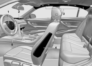
Controls At a glance
1 System on/off, interrupt 2 Resume speed 3 Store speed 4 Store, maintain/change speed
Switching on
Press the button on the steering wheel.
The marking in the speedometer is set to the current speed. Cruise control can be used. Switching off
Deactivated or interrupted system If the system is deactivated or interrupted, actively intervene by braking and, if necessary, with evasive maneuvers; otherwise, there is the danger of an accident occurring.◀
122
Online Edition for Part no. 01 40 2 903 880 - 07 12 490
Press the button.
▷ If active: press twice. ▷ If interrupted: press once. The displays go out. The stored desired speed is deleted. Interrupting the system
When active, press the button.
The system is automatically interrupted if: ▷ The brakes are applied. ▷ The clutch pedal is depressed for a few sec‐
onds or released while a gear is not en‐ gaged.
▷ The transmission position D is disengaged. ▷ DTC Dynamic Traction Control is activated
or DSC is deactivated.
▷ DSC is actively controlling stability. Maintaining/storing the current speed
Press the button.
Or
Press the rocker switch while the system is in‐ terrupted. When the system is switched on, the current speed is maintained and stored as the desired speed. It is displayed in the speedometer and briefly displayed in the instrument cluster, Displays in the speedometer, refer to page 124.
Driving comfort
Controls
When cruise control is maintained or stored, DSC Dynamic Stability Control is switched on, if necessary. Changing/maintaining speed The rocker switch can be pressed while the sys‐ tem is interrupted in order to maintain and store the current speed.
Adapting the desired speed Adapt the desired speed to the road con‐ ditions and be ready to brake at all times; other‐ wise, there is the danger of an accident occur‐ ring.◀
Press the rocker switch up or down repeatedly until the desired speed is set. If active, the displayed speed is stored and the vehicle reaches the stored speed if the road is clear. ▷ Each time the rocker switch is pressed to the
point of resistance, the desired speed in‐ creases or decreases by approx. 1 mph/1 km/h.
▷ Each time the rocker switch is pressed past
the point of resistance, the desired speed increases or decreases by a maximum of 5 mph/10 km/h.
▷ Pressing the rocker switch to the resistance point and holding it there accelerates or de‐ celerates the vehicle without requiring pres‐ sure on the accelerator. After the rocker switch is released, the vehicle maintains its final speed. Pressing the switch beyond the resistance point causes the vehicle to ac‐ celerate more rapidly.
Online Edition for Part no. 01 40 2 903 880 - 07 12 490
123
Controls
Driving comfort
Resuming the desired speed
Press the button.
The stored speed is reached and maintained. Displays in the instrument cluster Indicator lamp
Depending on how the vehicle is equip‐ ped, the indicator lamp in the instrument cluster indicates whether the system is
switched on.
▷ Signal tones. ▷ Visual display. General information Measurements are made by ultrasound sensors in the bumpers. The range is approx. 6 ft/2 m. An acoustic warning is first given: ▷ By the front sensors and two rear corner
sensors at approx. 24 in/60 cm.
▷ By the rear middle sensors at approx.
5 ft/1.50 m.
Desired speed
Notes
Check the traffic situation as well PDC cannot serve as a substitute for the driver's personal judgment of the traffic situa‐ tion. Check the traffic situation around the vehi‐ cle with your own eyes. Otherwise, an accident could result from road users or objects located outside of the PDC detection range. Loud noises from outside and inside the vehicle may prevent you from hearing the PDC's signal tone.◀
Avoid driving quickly with PDC Avoid approaching an object quickly.
Avoid driving away quickly while PDC is not yet active. For technical reasons, the system may other‐ wise be too late in issuing a warning.◀
▷ The marking lights up green:
the system is active.
▷ The marking lights up or‐ ange: the system has been interrupted.
▷ The marking does not light up: the system is
switched off.
With instrument display: the symbol is displayed in the speedometer similarly to the mark for the desired speed.
Brief status display
Selected desired speed.
If --- appears briefly on the display for Check Control messages, it is possible that the system requirements for operation are currently not met.
PDC Park Distance Control The concept PDC supports you when parking. Objects that you are approaching slowly in front of or behind your vehicle are indicated with:
124
Online Edition for Part no. 01 40 2 903 880 - 07 12 490
At a glance Button in the vehicle
PDC Park Distance Control
Switching on/off Switching on automatically Select transmission position R with the engine running. Automatic deactivation during forward travel The system switches off when a certain driving distance or speed is exceeded. Switch the system back on if necessary. Switching on/off manually
Press the button.
▷ On: the LED lights up. ▷ Off: the LED goes out. In addition to the PDC Park Distance Control, the backup camera, refer to page 126, can be switched on. Switching on the backup camera via the iDrive With PDC activated:
"Rear view camera"
The backup camera image is displayed. The set‐ ting is stored for the remote control currently in use.
Driving comfort
Controls
Display Signal tones When approaching an object, an intermittent tone is sounded that indicates the position of the object. For example, if an object is detected to the left rear of the vehicle, a signal tone sounds from the left rear speaker. The shorter the distance to the object becomes, the shorter the intervals. If the distance to a detected object is less than approx. 10 in/25 cm, a continuous tone is sounded. If objects are located both in front of and behind the vehicle, an alternating continuous signal is sounded. The intermittent tone is interrupted after approx. 3 seconds: ▷ If the vehicle stops in front of an object that is detected by only one of the corner sen‐ sors.
▷ If moving parallel to a wall. The signal tone is switched off: ▷ When the vehicle moves away from an ob‐
ject by more than approx. 4 in/10 cm.
▷ When transmission position P is engaged. Volume The volume of the PDC signal can be adjusted, refer to user's manual for Navigation, Entertain‐ ment and Communication. The setting is stored for the remote control cur‐ rently in use. Visual warning The approach of the vehicle to an object can be shown on the Control Display. Objects that are farther away are displayed on the Control Dis‐ play before a signal tone sounds. A display appears as soon as Park Distance Control (PDC) is activated.
Online Edition for Part no. 01 40 2 903 880 - 07 12 490
125
Controls
Driving comfort
The range of the sensors is represented in col‐ ors: red, green and yellow. If the backup camera image was selected last, it again appears on the display. To switch to PDC: "Rear view camera" Select the symbol 1.
on the Control Display.
2. Press the controller. The setting is stored for the remote control cur‐ rently in use. System limits Limits of ultrasonic measurement The detection of objects can reach the physical limits of ultrasonic measurement, e.g.: ▷ With tow bars and trailer hitches. ▷ With thin or wedge-shaped objects. ▷ With low objects. ▷ With objects with corners and sharp edges. Low objects already displayed, e.g., curbs, can move into the blind area of the sensors before or after a continuous tone sounds. High, protruding objects such as ledges may not be detected. False warnings PDC may issue a warning under the following conditions even though there is no obstacle within the detection range: ▷ In heavy rain. ▷ When sensors are very dirty or covered in
ice.
▷ When sensors are covered in snow. ▷ On rough road surfaces. ▷ In large buildings with right angles and
smooth walls, e.g., in underground garages.
▷ In heavy exhaust. ▷ Due to other ultrasound sources, e.g.,
sweeping machines, high pressure steam cleaners or neon lights.
The malfunction is signaled by a continuous tone alternating between the front and rear speakers. As soon as the malfunction due to other ultrasound sources is no longer present, the system is again fully functional.
Malfunction A Check Control message is displayed. The range of the sensors is shown as a shaded area on the Control Display. PDC has failed. Have the system checked. To ensure full operability: ▷ Keep the sensors clean and free of ice. ▷ When using high-pressure washers, do not spray the sensors for long periods and main‐ tain a distance of at least 12 in/30 cm.
Surround View The concept Surround View includes the following systems: ▷ Backup camera, refer to page 126
▷ Side View, refer to page 131. ▷ Top View, refer to page 129. It assists the driver when parking, maneuvering and on blind driveways and intersections.Backup camera The concept The backup camera provides assistance in park‐ ing and maneuvering backwards. The area be‐ hind the vehicle is shown on the Control Display. Notes
Check the traffic situation as well Check the traffic situation around the ve‐ hicle with your own eyes. Otherwise, an accident could result from road users or objects located outside the picture area of the backup camera.◀
126
Online Edition for Part no. 01 40 2 903 880 - 07 12 490
Driving comfort
Controls
Switching on/off manually
Press the button.
▷ On: the LED lights up. ▷ Off: the LED goes out. The PDC is shown on the Control Display. Switch on the backup camera via the iDrive, refer to page 125. Switching on the backup camera via the iDrive With PDC activated:
"Rear view camera"
The backup camera image is displayed. The set‐ ting is stored for the remote control currently in use. Display on the Control Display Functional requirement ▷ The backup camera is switched on. ▷ The trunk lid is fully closed. Activating the assistance functions More than one assistance function can be active at the same time. ▷ Parking aid lines
"Parking aid lines"
Pathway and turning circle lines are dis‐ played.
▷ Obstacle marking
"Obstacle marking"
Spatially-shaped markings are displayed.
At a glance Button in the vehicle
Backup camera
Camera
The camera lens is located in the handle of the trunk lid. The image quality may be impaired by dirt. Clean the lens, refer to page 216.
Switching on/off Switching on automatically Select transmission position R with the engine running. The backup camera image is displayed if the system was switched on via the iDrive. Automatic deactivation during forward travel The system switches off when a certain driving distance or speed is exceeded. Switch the system back on if necessary.
Online Edition for Part no. 01 40 2 903 880 - 07 12 490
127
Controls
Driving comfort
Pathway lines
Obstacle marking
▷ Can be shown in the backup camera image
when in transmission position R.
▷ Help you to estimate the space required when parking and maneuvering on level roads.
▷ Are dependent on the current steering angle and are continuously adjusted to the steer‐ ing wheel movements.
Turning circle lines
▷ Spatially-shaped markings can be shown in
the backup camera image.
Their colored steps match the markings of the PDC. This simplifies estimation of the distance to the object shown.
Parking using pathway and turning circle lines 1. Position the vehicle so that the turning circle lines lead to within the limits of the parking space.
▷ Can be shown in the backup camera image. ▷ Show the course of the smallest possible
turning circle on a level road.
▷ Only one turning circle line is displayed
when the steering wheel is turned.
2. Turn the steering wheel to the point where the pathway line covers the corresponding turning circle line.
128
Online Edition for Part no. 01 40 2 903 880 - 07 12 490
Display settings Brightness With the backup camera switched on: 1. 2. Turn the controller until the desired setting
Select the symbol.
is reached and press the controller.
Contrast With the backup camera switched on: 1. 2. Turn the controller until the desired setting
Select the symbol.
is reached and press the controller.
System limits Detection of objects High, protruding objects such as ledges may not be detected by the backup camera.
Top View The concept Top View assists you in parking and maneuver‐ ing. The area around the doors and the road area around the vehicle are shown on the Control Display for this purpose. General information The image is captured by two cameras integrated in the exterior mirrors and by the backup camera. The range is at least 7 ft/2 m to the side and rear. In this way, obstacles up to the height of the ex‐ terior mirrors are detected early.
Driving comfort
Controls
Notes
Check the traffic situation as well Check the traffic situation around the ve‐ hicle with your own eyes. Otherwise, an accident could result from road users or objects located outside the picture area of the cameras.◀
At a glance Button in the vehicle
Top View
Cameras
The lenses of the Top View cameras are located at the bottom of the exterior mirror housings. The image quality may be impaired by dirt. Clean the lens, refer to page 216.
Switching on/off Switching on automatically Select transmission position R with the engine running.
Online Edition for Part no. 01 40 2 903 880 - 07 12 490
129
Controls
Driving comfort
The Top View and PDC images are displayed if the system is switched on via iDrive. Automatic deactivation during forward travel The system switches off when a certain driving distance or speed is exceeded. Switch the system back on if necessary. Switching on/off manually
Press the button.
▷ On: the LED lights up. ▷ Off: the LED goes out. Top View is displayed, switch on the backup camera via the iDrive, refer to page 130. Switching on the backup camera via the iDrive With Top View switched on:
"Rear view camera"
The backup camera image is displayed. The set‐ ting is stored for the remote control currently in use. Display Visual warning The approach of the vehicle to an object can be shown on the Control Display. When the distance to an object is small, a red bar is shown in front of the vehicle, as it is in the PDC display.
The display appears as soon as Top View is ac‐ tivated. If the backup camera image was selected last, it again appears on the display when reverse gear is selected. To switch to Top View:
"Rear view camera" Select the symbol on
the Control Display. The setting is stored for the remote control cur‐ rently in use. Brightness With Top View switched on: 1. 2. Turn the controller until the desired setting
"Brightness"
is reached and press the controller.
Contrast With Top View switched on: 1. 2. Turn the controller until the desired setting
"Contrast"
is reached and press the controller. Displaying the turning circle and pathway lines ▷ The static, red turning circle line shows the
space needed to the side of the vehicle when the steering wheel is turned all the way.
▷ The variable, green pathway line assists you in assessing the amount of space actually needed to the side of the vehicle.
130
Online Edition for Part no. 01 40 2 903 880 - 07 12 490
Driving comfort
Controls
The pathway line is dependent on the cur‐ rent steering angle and is continuously ad‐ justed with the steering wheel movement.
At a glance Button in the vehicle
"Parking aid lines"
Turning circle and pathway lines are displayed. System limits Top View cannot be used in the following situa‐ tions: ▷ With a door open. ▷ With the trunk lid open. ▷ With an exterior mirror folded in. ▷ In poor light. A Check Control message is displayed in some of these situations.
Side View The concept Side View provides an early look at cross traffic at blind driveways and intersections. Road users concealed by obstacles to the left and right of the vehicle can only be detected relatively late from the driver's seat. To improve visibility, two cameras in the front of the vehicle record the traffic situation on each side. Notes The images from both cameras are shown si‐ multaneously on the Control Display.
Check the traffic situation as well Check the traffic situation around the ve‐ hicle on blind driveways and intersections with your own eyes. Otherwise, an accident could re‐ sult from road users or objects located outside the picture area of the Side View cameras.◀
Side View
Cameras
Two cameras integrated in the bumpers capture the image. The two camera lenses are located on the sides of the bumper. The image quality may be impaired by dirt. Clean the lens, refer to page 216.
Switching on/off Switching on/off manually
Press the button.
Automatic deactivation during forward travel The system switches off when a certain driving distance or speed is exceeded.
Online Edition for Part no. 01 40 2 903 880 - 07 12 490
131
Controls
Driving comfort
Switch the system back on if necessary. Display The traffic area to the left and right is displayed on the Control Display.
Head-up Display The concept
Guidelines at the bottom of the image show the position of the front of the vehicle.
Brightness With the Side View switched on: 1. 2. Turn the controller until the desired setting
"Brightness"
is reached and press the controller.
Contrast With the Side View switched on: 1. 2. Turn the controller until the desired setting
"Contrast"
is reached and press the controller.
System limits The cameras capture a maximum range of 330 ft/100 m.
This system projects important information into the driver's field of vision, e.g., the speed. In this way, the driver can get information with‐ out averting his or her eyes from the road.
Display visibility The visibility of the displays in the Head-up Dis‐ play is influenced by: ▷ Certain sitting positions. ▷ Objects on the cover of the Head-up Dis‐
play.
▷ Sunglasses with certain polarization filters. ▷ Wet roads. ▷ Unfavorable light conditions. If the image is distorted, check the basic set‐ tings. Switching on/off 1. "Settings" 2. "Head-up display" 3. "Head-up display"
Switch the Head-up Display ON/OFF as re‐ quired. Display Overview ▷ Speed. ▷ Navigation system.
132
Online Edition for Part no. 01 40 2 903 880 - 07 12 490
▷ Check Control messages. ▷ Collision warning. ▷ Speed limit detection. ▷ Cruise control. ▷ Selection list from the instrument cluster. Some of this information is only displayed briefly as needed. Selecting displays in the Head-up Display 1. "Settings" 2. "Head-up display" 3. "Displayed information" 4. Select the desired displays in the Head-up
Display.
The settings are stored for the remote control currently in use. Setting the brightness The brightness is automatically adjusted to the ambient light. The basic setting can be adjusted manually. 1. "Settings" 2. "Head-up display" 3. "Brightness" 4. Turn the controller.
The brightness is adjusted.
When the low beams are switched on, the brightness of the Head-up Display can be addi‐ tionally influenced using the instrument lighting, refer to page 90. The setting is stored for the remote control cur‐ rently in use. Adjusting the height 1. "Settings" 2. "Head-up display" 3. "Height" 4. Turn the controller.
The height is adjusted.
Driving comfort
Controls
The setting is stored for the remote control cur‐ rently in use. Setting the rotation 1. "Settings" 2. "Head-up display" 3. "Rotation" 4. Turn the controller.
Rotation is set.
The setting is stored for the remote control cur‐ rently in use. Special windshield The windshield is part of the system. The shape of the windshield makes it possible to display a precise image. A film in the windshield prevents double images from being displayed. Therefore, have the special windshield replaced by a service center only.
Parking assistant The concept
This system assists the driver in parking parallel to the road. Ultrasound sensors measure parking spaces on both sides of the vehicle. The parking assistant calculates the best pos‐ sible parking line and takes control of steering during the parking procedure.
Online Edition for Part no. 01 40 2 903 880 - 07 12 490
133
Controls
Driving comfort
A component of the parking assistant is the PDC Park Distance Control, refer to page 124. Notes
Personal responsibility The parking assistant does not relieve the driver of responsibility for the vehicle during the parking procedure. Watch the parking space and parking procedure closely and intervene if necessary; otherwise, there is the danger of an accident.◀ Changes to the parking space Changes to the parking space after it was measured are not taken into account by the sys‐ tem. Therefore, always be alert and ready to inter‐ vene; otherwise, there is the danger of an acci‐ dent occurring.◀
Transporting loads Loads that extend beyond the perimeter of the vehicle are not taken into account by the system during the parking procedure. Therefore, always be alert and ready to inter‐ vene; otherwise, there is the danger of an acci‐ dent occurring.◀
Curbs The parking assistant may steer the vehi‐
cle over or onto curbs. Therefore, always be alert and ready to inter‐ vene; otherwise, the wheels, tires, or the vehicle may become damaged.◀ An engine that has been switched off by the Auto Start Stop function is restarted automati‐ cally when the parking assistant is activated. Requirements For measuring parking spaces ▷ Maximum speed while driving forward ap‐
prox. 22 mph/35 km/h.
▷ Maximum distance to row of parked vehi‐
cles: 5 ft/1.5 m.
▷ When parking in parking spaces on the driv‐ er's side, the corresponding turn signal must be set.
Suitable parking space ▷ Gap between two objects with a minimum
length of approx. 5 ft/1.5 m.
▷ Minimum length of the gap: own vehicle's
length plus approx 4 ft/1.2 m.
▷ Minimum depth: approx. 5 ft/1.5 m. For parking procedure Closed doors. At a glance Button in the vehicle
Parking assistant
Ultrasound sensors
The ultrasound sensors for measuring parking spaces are located on the wheel arches.
134
Online Edition for Part no. 01 40 2 903 880 - 07 12 490
Driving comfort
Controls
System status
The status is displayed with symbols.
Gray: parking space search. Blue: the system is activated. A suitable parking space was found.
The parking procedure is active. Steering control has been seized.
Status of the parking space search
To ensure full operability: ▷ Keep the sensors clean and free of ice. ▷ When using high-pressure washers, do not spray the sensors for long periods and main‐ tain a distance of at least 12 in/30 cm.
Switching on/off Switching on with the button
Press the button. The LED lights up.
The current status of the parking space search is indicated on the Control Display.
Parking assistant is activated automatically.
Switching on with reverse gear Shift into reverse. The current status of the parking space search is indicated on the Control Display. Activate: symbol in the Control Display. Switching off The system can be deactivated as follows: ▷
"Parking Assistant" Select the
Press the button.
▷ Switch off the ignition. Display on the Control Display Activating/deactivating the system
Symbol Meaning
Gray: the system is not available. White: the system is available but not activated. The system is activated.
▷ Gray, arrow 1: parking space search. ▷ Blue, arrow 2: parking space is suitable.
The vehicle is parked in the parking space if the parking procedure is active.
▷ No display: no parking space search.
Online Edition for Part no. 01 40 2 903 880 - 07 12 490
135
Controls
Driving comfort
Parking using the parking assistant
Check the traffic situation as well Loud sounds outside and within the vehi‐ cle can drown out the signal tones of the parking assistant and PDC. Check the traffic situation around the vehicle with your own eyes; otherwise, there is the dan‐ ger of an accident.◀ 1. Switch on the parking assistant and activate
it if necessary. The status of the parking space search is in‐ dicated on the Control Display.
2. Follow the instructions on the Control Dis‐
play. To achieve the best possible parking posi‐ tion, wait for the automatic steering wheel movement after the gear change when the vehicle is stationary. The end of the parking procedure is indi‐ cated on the Control Display.
3. Adjust the parking position yourself if nec‐
essary.
Interrupting manually The parking assistant can be interrupted at any time: ▷
"Parking Assistant" Select the symbol on
the Control Display.
▷
Press the button.
Interrupting automatically The system is interrupted automatically in the following situations: ▷ If the driver grasps the steering wheel or if
he takes over steering.
▷ If a gear is selected that does not match the
instruction on the Control Display.
▷ If a turn signal is activated in the opposite direction to the desired side for parking.
▷ If the vehicle speed exceeds approx.
6 mph/10 km/h.
▷ On snow-covered or slippery road surfaces
if necessary.
▷ If doors are open. ▷ If the Park Distance Control PDC displays
clearances that are too small.
▷ If a maximum number of parking attempts or
the time taken for parking is exceeded.
A Check Control message is displayed. Continuing An interrupted parking procedure can be con‐ tinued if necessary. Follow the instructions on the Control Display to do this. System limits No parking assistance The parking assistant does not offer assistance in the following situations: ▷ In tight curves. Functional limitations The system may not be fully functional in the following situations: ▷ When sensors are dirty or iced over. ▷ In heavy fog, rain or snowfall. ▷ On bumpy road surfaces such as gravel
roads.
▷ When leaves or snow has collected in the
parking space.
Limits of ultrasonic measurement The detection of objects can reach the physical limits of ultrasonic measurement, e.g. in the fol‐ lowing circumstances: ▷ With tow bars and trailer hitches. ▷ With thin or wedge-shaped objects.
136
Online Edition for Part no. 01 40 2 903 880 - 07 12 490
Driving comfort
Controls
▷ With elevated, protruding objects such as
ledges or cargo.
▷ With objects with corners and sharp edges. ▷ With objects with a fine surface structure,
such as fences.
Low objects already displayed, e.g., curbs, can move into the blind area of the sensors before or after a continuous tone sounds. High, protruding objects such as ledges may not be detected. The parking assistant may identify parking spaces that are not suitable for parking. Malfunction A Check Control message is displayed. The parking assistant failed. Have the system checked.
Online Edition for Part no. 01 40 2 903 880 - 07 12 490
137
Controls
Climate control
Climate control Vehicle equipment All standard, country-specific and optional equipment that is offered in the model series is described in this chapter. Therefore, equipment
Automatic climate control
is also described that is not available in a vehicle, e. g., because of the selected optional equip‐ ment or country variant. This also applies for safety-related functions and systems.
1 Seat heating, left 48
2 Vent settings 3 Rear window defroster 4 Air flow 5 AUTO program6 Temperature 7 Seat heating, right 48
8 Cooling function 9 Recirculated-air mode 10 Interior temperature sensor138
Online Edition for Part no. 01 40 2 903 880 - 07 12 490
Climate control
Controls
Climate control functions in detail Manual air distribution
Turn the wheel to select the de‐ sired program or the desired in‐ termediate setting.
The cooling function, refer to page 139, is switched on automatically with the AUTO pro‐ gram. Temperature
Turn the wheel to set the desired temperature.
▷ ▷ ▷
Windows. Upper body region. Windows, upper body region, and foot‐
well.
Footwell.
▷ Defrosting windows and removing condensation Direct the air distribution toward windows, in‐ crease the air flow and temperature, and, if nec‐ essary, use the cooling function. Rear window defroster Press the button. The rear window defroster switches off
automatically after a certain period of time.
Air flow, manual
Press the left or right side of the button: decrease or increase air flow.
The air flow of the air conditioner may be re‐ duced automatically to save battery power. AUTO program
Press the button. Air flow, air distribution, and tempera‐
ture are controlled automatically. Depending on the selected temperature and outside influences, the air is directed to the windshield, side windows, upper body, and into the footwell.
The automatic climate control reaches this tem‐ perature as quickly as possible, if necessary by increasing the cooling or heating output, and then keeps it constant. Avoid rapidly switching between different tem‐ perature settings. The automatic climate control will not have sufficient time to adjust the set temperature. Cooling function The passenger compartment can only be cooled with the engine running.
Press the button. The air is cooled and dehumidified and, depending on the temperature setting, warmed again. Depending on the weather, the windshield may fog up briefly when the engine is started. The cooling function is switched on automati‐ cally with the AUTO program. When using the automatic climate control, con‐ densation water, refer to page 162, develops that exits underneath the vehicle. Recirculated-air mode You can respond to unpleasant odors or pollu‐ tants in the immediate environment by tempo‐ rarily suspending the supply of outside air. The system then recirculates the air currently within the vehicle.
Press the button repeatedly to select an operating mode:
Online Edition for Part no. 01 40 2 903 880 - 07 12 490
139
Controls
Climate control
▷ LED off: outside air flows in continuously. ▷ LED on, recirculated-air mode: the supply of
outside air into the vehicle is permanently blocked.
If the windows fog over, switch off recirculated- air mode and increase the air volume, if neces‐ sary.
Continuous recirculated-air mode The recirculated-air mode should not be used for an extended period of time, as the air quality inside the vehicle deteriorates steadily.◀
Switching the system on/off Switching off
Press the left button for the minimum speed.
Switching on Press any button except ▷ Rear window defroster. ▷ Seat heating. Microfilter In external and recirculated air mode the micro‐ filter filters dust and pollen out of the air. This filter should be replaced during scheduled maintenance, refer to page 193, of your vehicle.
Automatic climate control with enhanced features
1 Seat heating, left 48
2 Temperature, left 3 AUTO program4 Display 5 Maximum cooling 6 Temperature, right
140
Online Edition for Part no. 01 40 2 903 880 - 07 12 490
Climate control
Controls
7 Seat heating, right 48
8 Cooling function 9 Automatic recirculated-air control/recircu‐lated-air mode
10 Air distribution, right 11 Air flow, AUTO intensity
12 Air distribution, left 13 Rear window defroster 14 Interior temperature sensor — always keep
15 Defrosting windows and removing conden‐
clear
sation
Climate control functions in detail Temperature
Turn the wheel to set the desired temperature.
The automatic climate control reaches this tem‐ perature as quickly as possible, if necessary by increasing the cooling or heating output, and then keeps it constant. Avoid rapidly switching between different tem‐ perature settings. The automatic climate control will not have sufficient time to adjust the set temperature. AUTO program
Press the button. Air flow, air distribution, and tempera‐
ture are controlled automatically. Depending on the selected temperature, AUTO intensity, and outside influences, the air is di‐ rected to the windshield, side windows, upper body, and into the footwell. The cooling function, refer to page 141, is switched on automatically with the AUTO pro‐ gram. At the same time, a condensation sensor con‐ trols the program so as to prevent window con‐ densation as much as possible.
Intensity of the AUTO program With the AUTO program switched on, automatic control of the air flow and air distribution can be adjusted.
Press the left or right side of the button: decrease or increase the intensity.
The selected intensity is shown on the display of the automatic climate control. Maximum cooling
Press the button. The system is set to the lowest tem‐
perature, maximum air flow and recirculated-air mode. Air flows out of the vents for the upper body re‐ gion. Open them for this purpose. The air is cooled fastest when the engine is run‐ ning. The air flow can be adjusted when the program is active. Cooling function The passenger compartment can only be cooled with the engine running.
Press the button. The air is cooled and dehumidified and, depending on the temperature setting, warmed again. Depending on the weather, the windshield may fog up briefly when the engine is started. The cooling function is switched on automati‐ cally with the AUTO program.
Online Edition for Part no. 01 40 2 903 880 - 07 12 490
141
Controls
Climate control
When using the automatic climate control, con‐ densation water, refer to page 162, develops that exits underneath the vehicle. Automatic recirculated-air control/ recirculated-air mode You can respond to unpleasant odors or pollu‐ tants in the immediate environment by tempo‐ rarily suspending the supply of outside air. The system then recirculates the air currently within the vehicle.
Press the button repeatedly to select an operating mode:
▷ LEDs off: outside air flows in continuously. ▷ Left LED on, automatic recirculated-air con‐ trol: a sensor detects pollutants in the out‐ side air and controls the shutoff automati‐ cally.
▷ Right LED on, recirculated-air mode: the
supply of outside air into the vehicle is per‐ manently blocked.
If the windows are fogged over, switch off the recirculated-air mode and press the AUTO but‐ ton to utilize the condensation sensor. Make sure that air can flow onto the windshield.
Continuous recirculated-air mode The recirculated-air mode should not be used for an extended period of time, as the air quality inside the vehicle deteriorates steadily.◀
Manual air distribution
Press the button repeatedly to select a program:
▷ Upper body region. ▷ Upper body region and footwell. ▷ Footwell. ▷ Windows and footwell: driver's side only. ▷ Windows, upper body region and footwell:
driver's side only.
If the windows are fogged over, press the AUTO button to utilize the condensation sensor.
Air flow, manual To be able to manually adjust the air flow, switch off the AUTO program first.
Press the left or right side of the button: decrease or increase air flow.
The selected air flow is shown on the display of the automatic climate control. The air flow of the automatic climate control may be reduced automatically to save battery power. Rear window defroster Press the button. The rear window defroster switches off
automatically after a certain period of time.
Defrosting windows and removing condensation
Press the button. Ice and condensation are quickly re‐ moved from the windshield and the front side windows. The air flow can be adjusted when the program is active. If the windows are fogged over, you can also switch on the cooling function or press the AUTO button to utilize the condensation sensor. Switching the system on/off Switching off
Press the left button for the minimum speed.
Switching on Press any button except ▷ Rear window defroster. ▷ Seat heating.
142
Online Edition for Part no. 01 40 2 903 880 - 07 12 490
Microfilter/activated-charcoal filter In external and recirculated air mode the micro‐ filter/activated charcoal filter filters dust, pollen, and gaseous pollutants out of the air. This filter should be replaced during scheduled maintenance, refer to page 193, of your vehicle.
Ventilation Front ventilation
▷ Lever for changing the air flow direction, ar‐
row 1.
▷ Thumbwheels for opening and closing the
vents continuously, arrows 2.
▷ Thumbwheel to vary the temperature, ar‐
row 3. Toward blue: colder. Toward red: warmer.
Adjusting the ventilation ▷ Ventilation for cooling:
Adjust the vent to direct the air in your di‐ rection, such as if the vehicle interior is hot from the sun.
▷ Draft-free ventilation:
Adjust the vent to let the air flow past you.
Climate control
Controls
Ventilation in the rear
▷ Thumbwheel for continuous opening and
closing of the vents, arrow 1.
▷ Thumbwheel to vary the temperature, ar‐
row 2. Toward blue: colder. Toward red: warmer.
▷ Lever for changing the air flow direction, ar‐
row 3.
Parked-car ventilation The concept The parked-car ventilation ventilates the vehicle interior and lowers its temperature, if necessary. The system can be switched on and off at any external temperature, either directly or by using two preset switch-on times. It remains switched on for 30 minutes. Open the vents to allow air to flow out. Operation can be performed via iDrive. Switching on/off directly 1. "Settings" 2. "Climate" 3. "Activate parked-car vent."
The symbol on the automatic climate control
flashes if the system is switched on.
Online Edition for Part no. 01 40 2 903 880 - 07 12 490
143
Controls
Climate control
Preselecting the switch-on time 1. "Settings" 2. "Climate" 3. "Timer 1:" or "Timer 2:" 4. Set the desired time. Activating the switch-on time 1. "Settings" 2. "Climate" 3. "Activate Timer 1" or "Activate Timer 2"
The symbol on the automatic climate control lights up when the switch-on time is activated. The symbol on the automatic climate control flashes when the system has been switched on. The system will only be switched on within the next 24 hours. After that, it needs to reactivated.
144
Online Edition for Part no. 01 40 2 903 880 - 07 12 490
Interior equipment Vehicle equipment All standard, country-specific and optional equipment that is offered in the model series is described in this chapter. Therefore, equipment is also described that is not available in a vehicle, e. g., because of the selected optional equip‐ ment or country variant. This also applies for safety-related functions and systems.
Integrated universal remote control The concept The integrated universal remote control can op‐ erate up to 3 functions of remote-controlled sys‐ tems such as garage door drives or lighting sys‐ tems. The integrated universal remote control replaces up to 3 different hand-held transmit‐ ters. To operate the remote control, the buttons on the interior rearview mirror must be program‐ med with the desired functions. The hand-held transmitter for the particular system is required in order to program the remote control.
During programming During programming and before activat‐ ing a device using the integrated universal re‐ mote control, ensure that there are no people, animals, or objects in the range of movement of the remote-controlled device; otherwise, there is a risk of injury or damage. Also follow the safety instructions of the hand- held transmitter.◀ Before selling the vehicle, delete the stored functions for the sake of security. Compatibility
If this symbol is printed on the packaging or in the instructions of the system to be controlled, the system is generally com‐
Interior equipment
Controls
patible with the integrated universal remote control. If you have any questions, please contact: ▷ Your service center. ▷ www.homelink.com on the Internet. HomeLink is a registered trademark of Johnson Controls, Inc. Controls on the interior rearview mirror
▷ LED, arrow 1. ▷ Buttons, arrow 2. ▷ The hand-held transmitter, arrow 3, is re‐
quired for programming.
Programming General information 1. Switch on the ignition. 2.
Initial setup: Press and hold the left and right button on the interior rearview mirror simultaneously for approximately 20 seconds until the LED on the interior rearview mirror flashes. This erases all programming of the buttons on the interior rearview mirror.
3. Hold the hand-held transmitter for the sys‐ tem to be controlled approx. 1 to 3 in/2.5 to 8 cm away from the buttons on the interior
Online Edition for Part no. 01 40 2 903 880 - 07 12 490
145
Controls
Interior equipment
rearview mirror. The required distance de‐ pends on the manual transmitter.
4. Simultaneously press and hold the button of the desired function on the hand-held trans‐ mitter and the button to be programmed on the interior rearview mirror. The LED on the interior rearview mirror will begin flashing slowly.
5. Release both buttons as soon as the LED
flashes more rapidly. When the LED is flash‐ ing faster, this indicates that the button on the interior rearview mirror has been pro‐ grammed. If the LED does not flash faster after at least 60 seconds, change the distance between the interior rearview mirror and the hand- held transmitter and repeat the step. Several more attempts at different distances may be necessary. Wait at least 15 seconds be‐ tween attempts. Canada: if programming with the hand-held transmitter was interrupted, hold down the interior rearview mirror button and repeat‐ edly press and release the hand-held trans‐ mitter button for 2 seconds.
6. To program other functions on other but‐
tons, repeat steps 3 to 5.
The systems can be controlled using the interior rearview mirror buttons. Special feature of the alternating-code wireless system If you are unable to operate the system after re‐ peated programming, please check if the sys‐ tem to be controlled features an alternating- code system. Read the system's operating manual, or press the programmed button on the interior rearview mirror longer. If the LED on the interior rearview mirror starts flashing rapidly and then stays lit constantly for 2 seconds, the system features an alternating-code system. Flashing and con‐ tinuous illumination of the LED will repeat for approximately 20 seconds.
For systems with an alternating-code system, the integrated universal remote control and the system also have to be synchronized. Please read the operating manual of the system being set up for information on how to syn‐ chronize the system. Synchronizing is easier with the aid of a second person. To synchronize: 1. Park the vehicle within range of the remote-
controlled system.
2. Program the relevant button on the interior
rearview mirror as described.
3. Locate and press the synchronizing button on the system being programmed. You have approx. 30 seconds for the next step.
4. Hold down the programmed button on the interior rearview mirror for approximately 3 seconds and then release it. If necessary, repeat this work step up to three times in or‐ der to finish synchronization. Once synchro‐ nization is complete, the programmed func‐ tion will be carried out.
Reprogramming individual buttons 1. Switch on the ignition. 2. Press and hold the interior rearview mirror
button to be programmed.
3. As soon as the interior rearview mirror LED
starts flashing slowly, hold the hand-held transmitter for the system to be controlled approx. 1 to 3 in/2.5 to 8 cm away from the buttons on the interior rearview mirror. The required distance depends on the manual transmitter.
4. Likewise, press and hold the button of the desired function on the hand-held transmit‐ ter.
5. Release both buttons as soon as the interior
rearview mirror LED flashes more rapidly. When the LED is flashing faster, this indi‐ cates that the button on the interior rearview mirror has been programmed. The system
146
Online Edition for Part no. 01 40 2 903 880 - 07 12 490
can then be controlled by the button on the interior rearview mirror. If the LED does not flash faster after at least 60 seconds, change the distance and repeat the step. Several more attempts at different distances may be necessary. Wait at least 15 seconds between attempts. Canada: if programming with the hand-held transmitter was interrupted, hold down the interior rearview mirror button and repeat‐ edly press and release the hand-held trans‐ mitter button for 2 seconds.
Controls
Before operation Before operating a system using the
integrated universal remote control, ensure that there are no people, animals, or objects within the range of movement of the remote-controlled system; otherwise, there is a risk of injury or damage. Also follow the safety instructions of the hand- held transmitter.◀ The system, such as the garage door, can be operated using the button on the interior rear‐ view mirror while the engine is running or when the ignition is started. To do this, hold down the button within receiving range of the system until the function is activated. The interior rearview mirror LED stays lit while the wireless signal is being transmitted. Deleting stored functions Press and hold the left and right button on the interior rearview mirror simultaneously for ap‐ proximately 20 seconds until the LED flashes rapidly. All stored functions are deleted. The functions cannot be deleted individually.
Interior equipment
Controls
Digital compass At a glance
1 Control button 2 Mirror display
Mirror display The point of the compass is displayed in the mirror when driving straight. Operating concept Various functions can be called up by pressing the control button with a pointed object, such as the tip of a ballpoint pen or similar object. The following setting options are displayed in suc‐ cession, depending on how long the control but‐ ton is pressed: ▷ Pressed briefly: turns display on/off. ▷ 3 to 6 seconds: compass zone setting. ▷ 6 to 9 seconds: compass calibration. ▷ 9 to 12 seconds: left/right-hand steering
setting.
▷ 12 to 15 seconds: language setting. Setting the compass zones Sets the particular compass zones on the vehi‐ cle so that the compass operates correctly; refer to World map with compass zones.
Online Edition for Part no. 01 40 2 903 880 - 07 12 490
147
Controls
Interior equipment
World map with magnetic zones
Procedure 1. Press and hold the control button for approx. 3 to 4 seconds. The number of the set com‐ pass zone appears in the mirror.
2. To change the zone setting, press the con‐ trol button quickly and repeatedly until the number of the compass zone corresponding to your location appears in the mirror.
The set zone is stored automatically. The com‐ pass is ready for use again after approximately 10 seconds. Calibrating the digital compass The digital compass must be calibrated in the event of the following: ▷ The wrong point of the compass is dis‐
played.
▷ The point of the compass displayed does not change despite changing the direction of travel.
▷ Not all points of the compass are displayed.
Procedure 1. Make sure that there are no large metallic
objects or overhead power lines near the ve‐ hicle and that there is sufficient room to drive around in a circle.
2. Set the currently applicable compass zone. 3. Press and hold the control button for approx. 6 to 7 seconds so that "C" appears on the display. Next, drive in a complete circle at least once at a speed of no more than 4 mph/7 km/h. If calibration is successful, the "C" is replaced by the points of the com‐ pass.
Left/right-hand steering The digital compass is already set for right or left-hand steering at the factory. Setting the language Press and hold the control button for approx. 12
to 13 seconds. Briefly press the control button again to switch between English "E" and Ger‐ man "O".148
Online Edition for Part no. 01 40 2 903 880 - 07 12 490
The setting is stored automatically after approx‐ imately 10 seconds.
Ashtray/cigarette lighter Ashtray Opening
Raise cover.
Emptying Take out the insert. Lighter
Danger of burns Only hold the hot lighter by its knob; oth‐ erwise, there is the danger of getting burned. Switch off the ignition and take the remote con‐ trol with you when leaving the vehicle so that children cannot use the lighter and burn them‐ selves.◀
Interior equipment
Controls
Push in the lighter. The lighter can be removed as soon as it pops back out.
Connecting electrical devices Note
Do not plug the charger into the socket Do not connect battery chargers to the
factory-installed sockets in the vehicle. Doing so may result in damage to the vehicle.◀
Sockets The lighter socket can be used as a socket for electrical equipment while the engine is running or when the ignition is switched on. The total load of all sockets must not exceed 140 watts at 12 volts. Do not damage the socket by using unsuitable connectors. Front center console