- Download PDF Manual
-
23
CAUTION
Too high
D After inserting the tab, make sure the tab and buckle are locked and that the belt is not twisted.
D Do not insert coins, clips, etc. in the buckle as this may prevent you from properly latching the tab and buckle.
D If the seat belt does not function normally, immediately contact your authorized Toyota CNG dealer. Do not use the seat until the seat belt is fixed. It cannot protect an adult occupant or your child from injury.
24
Adjust to a snug fit
Keep as low on hips as possible
Remove excess length of the belt and adjust the belt position. To shorten the belt, pull the free end of the belt. Position the lap belt as low as possible on your hips—not on your waist, then ad- just it to a snug fit.
CAUTION
High−positioned and loose−fitting lap belts could cause serious injuries due to sliding under the lap belt during a collision or other unintended result. Keep the lap belt positioned as low on hips as possible.
To release the belt, press the buckle−re- lease button.
D Remember that the extender pro- vided for you may not be safe when used on a different vehicle, or for another person or at a different seating position than the one origi- nally intended for.
—Seat belt extender If your seat belt cannot be fastened se- curely because it is not long enough, a personalized seat belt extender is avail- able from your authorized Toyota CNG dealer free of charge. Please contact your authorized Toyota CNG dealer so that he/she can order the proper required length for the extender. Bring to wear for proper measurement and selec- tion of length. Additional ordering informa- tion is available at your authorized Toyota CNG dealer.
the heaviest coat you expect
CAUTION
When using the seat belt extender, observe the following. Failure to fol- low these instructions could result in less effectiveness of the seat belt re- straint system in case of vehicle acci- dent, increasing the chance of per- sonal injury. D Never use the seat belt extender if you can fasten the seat belt without it.
To connect the extender to the seat belt, insert the tab into the seat belt buckle so that the “PRESS” signs on the buckle−release buttons of the ex- tender and the seat belt are both facing outward as shown. You will hear a click when the tab locks into the buckle. When releasing the seat belt, press on the buckle−release button on the extender, not on the seat belt. This helps prevent damage to the vehicle interior and extend- er itself. When not and store in the vehicle for future use.
in use, remove the extender
25
CAUTION
D After inserting the tab, make sure the tab and buckle are locked and that the seat belt extender is not twisted.
D Do not insert coins, clips, etc. in the buckle as this may prevent you from properly latching the tab and buckle.
D If the seat belt does not function normally, immediately contact your authorized Toyota CNG dealer. Do not use the seat until the seat belt is fixed. It cannot protect an adult occupant or your child from injury.
—Front seat belt pretensioners
The driver and front passenger’s seat belt pretensioners are designed to be activated in response to a severe fron- tal impact. When the airbag sensor detects the shock of a severe frontal impact, the front seat belt is quickly drawn back in by the re- tractor so that the belt snugly restrains the front seat occupants. The seat belt pretensioners are activated even with no passenger in the front seat.
26
This indicator comes on when the igni- tion key is turned to the “ACC” or “ON” position. It goes off after about 6 seconds. This means the front seat belt pretensioners are operating proper- ly. This warning the airbag sensor assembly, front airbag sen- sors, seat belt pretensioner assemblies, warning interconnecting wiring and power sources. (For details, see “Service reminder indicators and warning buzzers” in Chapter 1−5.)
light system monitors
light,
When a seat belt pretensioner is acti- vated, an operating noise may be heard and a small amount of smoke−like gas may be released. This gas is harmless and does not indicate that a fire is occur- ring. Once the seat belt pretensioner has been activated, the seat belt retractor remains locked.
CAUTION
Do not modify, remove, strike or open the front seat belt pretensioner as- semblies, airbag sensor or surround- ing area or wiring. Doing any of these may cause sudden operation of the front seat belt pretensioners or disable the system, which could re- sult in serious injury. Failure to follow these can result in serious injuries.
instructions
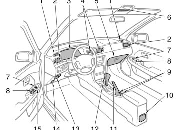
The seat belt pretensioner system mainly consists of the following components and their locations are shown in the illustra- tion. 1. Front airbag sensors 2. SRS warning light 3. Seat belt pretensioner assemblies 4. Airbag sensor assembly The seat belt pretensioner is controlled by the airbag sensor assembly. The airbag sensor assembly consists of a safing sen- sor and airbag sensor.
NOTICE
consulting
Do not perform any of the following changes without your authorized Toyota CNG dealer. Such interfere with proper changes can operation belt pretensioners in some cases. z Installation of electronic items such as a mobile two−way radio, cassette tape player or compact disc player z Repairs on or near the front seat
seat
the
of
belt retractor assemblies
z Modification of the suspension sys-
tem
z Modification of the front end struc-
ture
z Attachment of a grille guard (bull bar, kangaroo bar, etc.), snowplow, winches or any other equipment to the front end
z Repairs made on or near the front fenders, front end structure or con- sole
27
D If either front seat belt does not retract or can not be pulled out due to a malfunction or activation of the preten- sioner.
D The front seat belt pretensioner assem- bly or surrounding area has been dam- aged.
D The front part of the vehicle (shaded in the illustration) was involved in an accident that did not cause the seat belt pretensioners to operate.
D The front seat belt pretensioner assem- bly is scratched, cracked, or otherwise damaged.
SRS driver and front passenger airbags
The SRS (Supplemental Restraint Sys- tem) airbags are designed to provide further protection for the driver and front passenger when added to the pri- mary protection provided by the seat belts. In response to a severe frontal impact, the SRS airbags work together with the seat belts to help prevent or reduce injury by inflating, in order to decrease the likeli- hood of the driver’s or front passenger’s head or chest directly hitting the steering wheel or dashboard. The passenger airbag is activated even with no passenger in the front seat. Be sure to wear your seat belt.
the
following conditions occurs,
This front seat belt pretensioner system has a service reminder indicator to inform the driver of operating problems. If either of this indicates a malfunction of the airbags or pretensioners. Contact your authorized Toyota CNG dealer as soon as possible to service the vehicle. D The light does not come on when the ignition key is turned to the “ACC” or “ON” position, or remains on.
D The light comes on or flashes while
driving.
28
CAUTION
A driver or front passenger too close to the steering wheel or dashboard during airbag deployment can be killed or seriously injured. Toyota strongly recommends that: D The driver sit as far back as pos- sible from the steering wheel while still maintaining control of the ve- hicle.
D The front passenger sit as far back
as possible from the dashboard.
D All vehicle occupants be properly restrained using the available seat belts.
This indicator comes on when the igni- tion key is turned to the “ACC” or “ON” position. It goes off after about 6 seconds. This means the SRS airbags are operating properly. This warning the airbag sensor assembly, front airbag sen- sors, inflators, warning light, interconnect- ing wiring and power sources. (For details, see indicators and warning buzzers” in Chapter 1−5.)
light system monitors
reminder
“Service
The SRS airbag system is designed to activate in response to a severe frontal impact within the shaded area between the arrows in the illustration. There may be the case that the SRS air- bag will not activate with such an impact in which the occupant wearing the seat belt correctly would not get serious injury. The SRS airbags will deploy if the severi- ty of the impact is above the designed threshold level, comparable to an approxi- mate 25 km/h (15 mph) collision when impacting straight into a fixed barrier that does not move or deform.
29
this
level,
If the severity of the impact is below the above threshold the SRS airbags may not deploy. However, threshold velocity will be considerably higher if the vehicle strikes an object, such as a parked vehicle or sign pole, which can move or deform on impact, or if it is involved in an underride collision (e.g. a collision in which the nose of the vehicle “underrides”, or goes under, the bed of a truck, etc.). It is possible with collision severity at the marginal level of airbag sensor detection and activation that only one of your ve- hicle’s two airbags will deploy. For the safety of all occupants, be sure to always wear seat belts.
Collision rear
from
the
Collision from the side
Hitting a curb, edge of pavement or hard material
Falling into or jumping over a deep hole
Vehicle rollover
Landing hard or vehicle falling
The SRS airbags are not designed to inflate if the vehicle is subjected to a side or rear impact, if it rolls over, or if it is involved in a low−speed frontal collision.
The SRS airbags may deploy if a seri- ous impact occurs to the underside of your vehicle. Some examples are shown in the illustration.
30
the windshield as
A crash severe enough to inflate the air- bags may break the vehicle buckles. In vehicles with a pas- senger airbag the windshield may also be damaged by absorbing some of the force of the inflating airbag.
In a severe frontal impact, sensors detect deceleration and the system triggers the airbag inflators. Then a chemical reaction in the inflators momentarily fills the air- bags with non−toxic gas to help restrain the forward motion of the occupants. When the airbags inflate, they produce a fairly loud noise and release some smoke and residue along with non−toxic gas. This does not indicate a fire. This gas is nor- mally harmless, however, for those who have delicate skin, it may cause minor skin irritation. Be sure to wash off any residue as soon as possible to prevent minor skin irritation. Deployment of the airbags happens in a fraction of a second, so the airbags must inflate with considerable force. While the system is designed to reduce serious inju- ries, it may also cause minor burns or abrasions and swellings. Parts of the airbag module (steering wheel hub, dashboard) may be hot for several minutes, but the airbags themselves will not be hot. The airbags are designed to inflate only once.
The SRS airbag system mainly consists of the following components and their loca- tions are shown in the illustration. 1. Front airbag sensors 2. SRS warning light 3. Airbag module
for passenger (airbag
and inflator)
4. Airbag sensor assembly 5. Airbag module for driver (airbag and
inflator)
The airbag sensor assembly consists of a safing sensor and airbag sensor.
31
D Improperly seated and/or restrained infants and children can be killed or seriously injured by a deploying airbag. An infant or child who is too small to use a seat belt should be properly secured using a child restraint system. Toyota strongly recommends infants and children be placed in the rear seat of re- strained. The rear seat is the safest for in- structions concerning the installa- tion of a child restraint system, see “Child restraint” in this chapter.
the vehicle and properly
infants and children. For
that all
D Never put a rear−facing child re- straint system on the front seat be- cause the force of the rapid infla- tion of the passenger airbag can cause death or serious injury to the child.
CAUTION
D The SRS airbag system is designed only as a supplement to the prima- ry protection of the driver side and front passenger side seat belt sys- tems. The front seat occupants can be killed or seriously injured by an inflating airbag if they do not wear the available seat belts. During sud- den braking just before a collision, an unrestrained driver or front pas- senger can move forward into direct contact with or close proximity to the airbag which may then deploy during the collision. To obtain maxi- mum protection in an accident, the driver and all passengers in the ve- hicle must wear their seat belts. Wearing a seat belt during an acci- dent reduces the chances of death or serious injuries or being thrown out of the vehicle. For instructions and precautions concerning the seat belt system, see “Seat belts” in this chapter.
32
Move seat fully back
D A forward−facing child restraint sys- tem should be allowed to put on the front seat only when it is un- avoidable. Always move the seat as far back as possible, because the force of a deploying airbag could cause death or serious injury to the child.
D Do not sit on the edge of the seat or lean over the dashboard when the vehicle is in use. The airbags inflate with considerable speed and force; you may be killed or serious- ly injured. Sit up straight and well back in the seat, and always use your seat belt.
D For
instructions concerning
the installation of a child restraint sys- tem, see “Child restraint” in this chapter.
D Do not allow a child to stand up, or to kneel on the front passenger seat. The airbag inflates with con- siderable speed and force; the child may be killed or seriously injured. D Do not hold a child on your lap or in your arms. Use a child restraint system in the rear seat. For instruc- tions concerning the installation of a child restraint system, see “Child restraint” in this chapter.
33
D Do not modify or remove any wir- ing. Do not modify, remove, strike or open any components such as the steering wheel pad, steering wheel, column cover, front passen- ger airbag cover, front passenger airbag or airbag sensor assembly. Doing any of these may cause sud- den SRS airbag inflation or disable the system, which could result in death or serious injury. instructions Failure to follow these can result in death or serious inju- ries.
D Do not put objects or your pets on or in front of the dashboard or steering wheel pad that houses the airbag system. They might restrict inflation or cause death or serious injury as they are projected rear- ward by the force of deploying air- bags. Likewise, the driver and front passenger should not hold things in their arms or on their knees.
34
NOTICE
consulting
Do not perform any of the following changes without your authorized Toyota CNG dealer. Such changes can interfere with proper operation of the SRS airbag system in some cases. z Installation of electronic items such as a mobile two−way radio, cassette tape player or compact disc player z Modification of the suspension sys-
tem
z Modification of the front end struc-
ture
z Attachment of a grille guard (bull bar, kangaroo bar, etc.), snowplow, winches or any other equipment to the front end
z Repairs made on or near the front fenders, front end structure, con- sole, steering wheel or dashboard near the front passenger airbag
steering
column,
If either of
This SRS airbag system has a service reminder indicator to inform the driver of operating problems. the following conditions occurs, this indicates a malfunction of the airbags. Contact your authorized Toyota CNG dealer as soon as possible to service the vehicle. D The light does not come on when the ignition key is turned to the “ACC” or “ON” position, or remains on.
D The light comes on while driving.
In the following cases, contact your autho- rized Toyota CNG dealer as soon as pos- sible: D The SRS airbags have been inflated. D The front part of the vehicle (shaded in the illustration) was involved in an accident that did not cause the SRS airbags to inflate.
D The pad section of the steering wheel or cover (shaded in the illustration) is scratched, cracked, or otherwise damaged.
passenger
airbag
front
NOTICE
Do not disconnect the battery cables before contacting your authorized Toyota CNG dealer.
35
D A forward−facing child restraint sys- tem should be allowed to put on the front seat only when it is un- avoidable. Always move the seat as far back as possible, because the force of a deploying airbag could cause death or serious injury to the child.
D Make sure that you have complied with all installation instructions pro- vided restraint manufacturer and that the system is properly secured.
child
the
by
D Toyota strongly urges use of a proper child restraint system which conforms to the size of the child, and is put on the rear seat. Accord- ing to accident statistics, the child is safer when properly restrained in the rear seat than in the front seat. D Never put a rear−facing child re- straint system on the front seat. In the event of an accident, the force of the rapid inflation of the airbag can cause death or serious injury if a rear−facing child restraint system is put on the front seat.
D Unless it is unavoidable, do not put the
restraint system on
a child front seat.
Child restraint— —Child restraint precautions Toyota strongly urges the use of child restraint systems for children small enough to use them. The laws of all fifty states in the U.S.A. and Canada now require the use of a child restraint system. Your vehicle conforms to SAEJ1819. If a child is too large for a child restraint system, the child should sit in the rear seat and must be restrained using the vehicle’s seat belt. See “Seat belts” for details.
CAUTION
D For effective protection in automo- bile accidents and sudden stops, children must be properly re- strained using a seat belt or child restraint system depending on the age and size of the child. Holding a child in your arms is not a sub- stitute for a child restraint system. In an accident, the child can be crushed against the windshield, or between you and the vehicle’s inte- rior.
36
the manufacturer’s
—Child restraint system A child restraint system for a small child or baby must itself be properly restrained on the seat with either the lap belt or the lap portion of the lap/ shoulder belt. You must carefully con- sult instructions which accompany your child restraint system. To provide proper restraint, use a child restraint system following the manufactur- er’s instructions about the appropriate age and size of the child for the restraint sys- tem. Install the child restraint system correctly following the instructions provided by its manufacturer of the system. General di- rections are also provided under the fol- lowing illustrations. The child restraint system should be installed on the rear seat. According to accident statistics, the child is safer when properly restrained in the rear seat than in the front seat.
CAUTION
D Never put a rear−facing child re- straint system on the front seat. In the event of an accident, the force of the rapid inflation of the airbag can cause death or serious injury if a rear−facing child restraint system is put on the front seat.
D Unless it is unavoidable, do not put the
restraint system on
a child front seat.
D A forward−facing child restraint sys- tem should be allowed to put on the front seat only when it is un- avoidable. Always move the seat as far back as possible, because the force of a deploying airbag could cause death or serious injury to the child. D After
installing the child restraint system, make sure it is secured in place following the manufacturer’s instructions. If it is not restrained securely, it may cause death or se- rious the event of a sudden stop or accident.
the child
injury
to
in
When not using the child restraint system, keep it secured with the seat belt or place it in the trunk or somewhere other than the passenger compartment. This will pre- vent the event of a sudden stop or accident.
injuring passengers
from
in
it
37
—Types of child restraint system Child restraint systems are classified into the following 3 types depending on the child’s age and size. (A) Infant seat (B) Convertible seat (C) Booster seat Install the child restraint system following the instructions provided by its manufac- turer.
(A) Infant seat
(C) Booster seat
38
(B) Convertible seat
—Installation with 2−point type seat belt
(A) INFANT SEAT INSTALLATION An infant seat is used in rear−facing position only.
CAUTION
Do not put a rear−facing child re- straint system on the rear seat if it interferes with the lock mechanism of the front seats. This can cause severe injury to the child and front passen- ger in case of sudden braking or a collision.
1. Run
the
lap belt
the center
infant seat
through or around the instructions provided by its manufactur- er and insert the tab into the buckle taking care not to twist the lap belt.
following
39
CAUTION
D After inserting the tab, make sure the tab and buckle are locked and that the lap belt is not twisted.
D Do not insert coins, clips, etc. in the buckle as this may prevent you from properly latching the tab and buckle.
D If the seat belt does not function it cannot protect your normally, injury. Contact your child authorized Toyota CNG dealer im- mediately. Do not use the seat until the seat belt is fixed.
from
40
2. While pressing the infant seat
firmly against the seat cushion and seatback, tighten the lap belt by pulling its free end to hold the infant seat securely.
CAUTION
Push and pull the child restraint sys- tem in different directions to be sure it is secure. Follow all the installation instructions provided by its manufac- turer.
3. To remove the infant seat, press the
buckle−release button.
(B) CONVERTIBLE SEAT INSTALLATION A convertible seat is used in forward− facing and rear−facing position depend- ing on the child’s age and size. When installing, the manufacturer’s instructions about the applicable child’s age and size as well as directions for installing a child restraint system.
follow
CAUTION
Do not put a rear−facing child re- straint system on the rear seat if it interferes with the lock mechanism of the front seats. This can cause severe injury to the child and front passen- ger in case of sudden braking or a collision.
41
CAUTION
D After inserting the tab, make sure the tab and buckle are locked and that the lap belt is not twisted.
D Do not insert coins, clips, etc. in the buckle as this may prevent you from properly latching the tab and buckle.
D If the seat belt does not function it cannot protect your normally, injury. Contact your child authorized Toyota CNG dealer im- mediately. Do not use the seat until the seat belt is fixed.
from
2. While pressing
the convertible seat firmly against the seat cushion and seatback, tighten the lap belt by pulling its free end to hold the convertible seat securely.
1. Run
lap belt
the center
through or following around its by the instructions tab into manufacturer and the buckle taking care not to twist the lap belt.
the convertible seat provided insert the
42
—Installation with 3−point type seat belt
CAUTION
3. To remove the convertible seat, press
the buckle−release button.
Push and pull the child restraint sys- tem in different directions to be sure it is secure. Follow all the installation instructions provided by its manufac- turer.
(A) INFANT SEAT INSTALLATION An infant seat is used in rear−facing position only.
43
CAUTION
D Never put a rear−facing child re- straint system on the front seat be- cause the force of the rapid infla- tion of the passenger airbag can cause death or serious injury to the child.
D Do not put a rear−facing child re- straint system on the rear seat if it interferes with the lock mechanism of the front seats. This can cause severe injury to the child and front passenger in case of sudden brak- ing or a collision.
1. Run the lap and shoulder belt through or around the infant seat following the instructions provided by its manufactur- er and insert the tab into the buckle taking care not to twist the belt. Keep the lap portion of the belt tight.
44
CAUTION
D After inserting the tab, make sure the tab and buckle are locked and that the lap and shoulder portions of the belt are not twisted.
D Do not insert coins, clips, etc. in the buckle as this may prevent you from properly latching the tab and buckle.
D If the seat belt does not function it cannot protect your normally, injury. Contact your child authorized Toyota CNG dealer im- mediately. Do not use the seat until the seat belt is fixed.
from
2. Fully extend the shoulder belt to put it in the lock mode. When the belt is then retracted even slightly, it cannot be extended.
the
To hold infant seat securely, make sure the belt is in the lock mode before letting the belt retract.
3. While pressing the infant seat
firmly against the seat cushion and seatback, let the shoulder belt retract as far as it will go to hold the infant seat secure- ly.
45
CAUTION
Push and pull the child restraint sys- tem in different directions to be sure it is secure. Follow all the installation instructions provided by its manufac- turer.
4. To remove the infant seat, press the buckle−release button and allow the belt to retract completely. The belt will move to work for an adult or older child passen- ger.
freely again and be ready
(B) CONVERTIBLE SEAT INSTALLATION A convertible seat is used in forward− facing and rear−facing position depend- ing on the child’s age and size. When installing, follow the manufacturer’s in- structions about the applicable child’s age and size as well as directions for installing a child restraint system.
46
Move seat fully back
CAUTION
D Never put a rear−facing child re- straint system on the front seat be- cause the force of the rapid infla- tion of the passenger airbag can cause death or serious injury to the child.
D A forward−facing child restraint sys- tem should be allowed to put on the front seat only when it is un- avoidable. Always move the seat as far back as possible, because the force of a deploying airbag could cause death or serious injury to the child.
D Do not put a rear−facing child re- straint system on the rear seat if it interferes with the lock mechanism of the front seats. This can cause severe injury to the child and front passenger in case of sudden brak- ing or a collision.
47
CAUTION
D After inserting the tab, make sure the tab and buckle are locked and that the lap and shoulder portions of the belt are not twisted.
D Do not insert coins, clips, etc. in the buckle as this may prevent you from properly latching the tab and buckle.
D If the seat belt does not function it cannot protect your normally, injury. Contact your child authorized Toyota CNG dealer im- mediately. Do not use the seat until the seat belt is fixed.
from
2. Fully extend the shoulder belt to put it in the lock mode. When the belt is then retracted even slightly, it cannot be extended.
To hold the convertible seat securely, make sure the belt is in the lock mode before letting the belt retract.
1. Run the lap and shoulder belt through or around the convertible seat following its the instructions manufacturer and into the buckle taking care not to twist the belt. Keep the lap portion of the belt tight.
provided insert the
by tab
48
3. While pressing
the convertible seat firmly against the seat cushion and seatback, let the shoulder belt retract as far as it will go to hold the convert- ible seat securely.
CAUTION
Push and pull the child restraint sys- tem in different directions to be sure it is secure. Follow all the installation instructions provided by its manufac- turer.
4. To remove the convertible seat, press the buckle−release button and allow the belt to retract completely. The belt will move to work for an adult or older child passen- ger.
freely again and be ready
49
(C) BOOSTER SEAT INSTALLATION A booster seat is used in forward−fac- ing position only.
Move seat fully back
CAUTION
A forward−facing child restraint sys- tem should be allowed to put on the front seat only when it is unavoid- able. Always move the seat as far back as possible, because the force of a deploying airbag could cause death or serious injury to the child.
50
1. Sit the child on a booster seat. Run the lap and shoulder belt through or around the booster seat and child fol- lowing the instructions provided by its manufacturer and into the buckle taking care not to twist the belt.
insert
the
tab
Make sure the shoulder belt is correctly across the child’s shoulder and that the lap belt is positioned as low as possible on child’s hips. See “Seat belts” for de- tails.
CAUTION
D Always make sure the shoulder belt is positioned across the center of child’s shoulder. The belt should be kept away from child’s neck, but not falling off child’s shoulder. Fail- ure the amount of protection in an accident and cause serious injuries in a col- lision.
to do so could reduce
D If the seat belt does not function it cannot protect your normally, injury. Contact your child authorized Toyota CNG dealer im- mediately. Do not use the seat until the seat belt is fixed.
from
lap
D High−positioned
belts
and loose−fitting belts both could cause serious injuries due to sliding un- der the lap belt during a collision or other unintended result. Keep the lap belt positioned as low on hips as possible.
D For child’s safety, do not place the
shoulder belt under child’s arm.
D After inserting the tab, make sure the tab and buckle are locked and that the lap and shoulder portions of the belt are not twisted.
D Do not insert coins, clips, etc. in the buckle as this may prevent you from properly latching the tab and buckle.
2. To remove the child restraint system, press the buckle−release button and al- low the belt to retract.
51
Tilt steering wheel
Outside rear view mirrors—
CAUTION
D Do not adjust the steering wheel
while the vehicle is moving.
D After adjusting the steering wheel, try moving it up and down to make sure it is locked in position.
tilt
lever,
release
To change the steering wheel angle, hold the steering wheel, pull up the lock the steering wheel to the desired angle and release the lever. When the steering wheel is in a low posi- tion, it will spring up as you release the lock release lever.
52
Adjust the mirror so that you can just see the side of your vehicle in the mir- ror. Be careful when judging the size or dis- tance of any object seen in the outside rear view mirror on the passenger’s side. It is a convex mirror with a curved sur- face. Any object seen in a convex mirror will look smaller and farther away than when seen in a flat mirror. On some models, when you push the rear window defogger switch, the heater panels in the outside rear view mirrors will quick- ly clear the mirror surface.
—Power rear view mirror control
NOTICE
If ice should jam the mirror, do not operate the control or scrape the mir- ror face. Use a spray de−icer to free the mirror.
CAUTION
D Do not adjust the mirror while the vehicle is moving. It may cause the driver to mishandle the vehicle and an accident may occur resulting in personal injuries.
D Since the mirror surfaces can get hot, keep your hands off them when the defogger switch is on.
To adjust a mirror, use the switches. 1. Master switch—To select the mirror to
be adjusted Place the switch at “L” (left) or “R” (right). 2. Control
switch—To move
the mir- the desired
ror P ush direction.
the switch
in
Mirror can be adjusted when key is in the “ACC” or “ON” position.
53
Anti−glare inside rear view mirror
Sun visors—
CAUTION
Do not adjust the mirror while the vehicle is moving. It may cause the driver to mishandle the vehicle and an accident may occur resulting in personal injuries.
Adjust the mirror so that you can just see the rear of your vehicle in the mir- ror. To reduce glare from the headlights of the vehicle behind you during night driving, operate the lever on the lower edge of the mirror. Daylight driving—Lever at position 1
The reflection in the mirror has greater clarity at this position. Night driving—Lever at position 2
Remember that by reducing glare you also lose some rear view clarity.54
To block out glare, move the sun visor. To block out glare from the front—Swing down the sun visor (position 1). To block out glare from the side—Swing down the sun visor, remove it from the hook and swing it to the lateral side (posi- tion 2). If glare comes from obliquely behind you, extend the plate at the end of the visor (to position 3 or 4).
—Vanity mirrors
CAUTION
Do not extend the plate at the end of the sun visor when the visor is in the position 1. It can cover the anti−glare inside rear view mirror and obstruct the rear view.
To use the vanity mirrors, swing down the sun visor and open the cover.
55
56
Part 1
OPERATION OF INSTRUMENTS AND CONTROLS—Chapter 1−4
Lights, Wipers and DefoggerD Headlights and turn signals D Emergency flashers D Instrument panel light control D Interior light D Ignition switch light D Windshield wipers and washer D Rear window and outside
rear view mirror defoggers
Headlights and turn signals
NOTICE
To prevent the battery from being dis- charged, do not leave the lights on for a long period when the engine is not running.
tail,
license plate,
HEADLIGHTS To turn on the following lights: Twist the headlight/turn signal lever knob. Position 1—Parking, side marker and instrument panel lights Position 2—Headlights and all of above The lights automatically turn off when the driver’s door is opened with the ignition turned off. To turn them on again, turn the key to the “ON” position or actuate the headlight switch. If you are going to park for over one week, make sure the head- light switch is off.
the
57
Emergency flashers
High−Low beams—For high beams, turn the headlights on and push the lever away from you (position 1). Pull the lever to- ward you (position 2) for low beams. The headlight high beam light indicator (blue light) on the instrument panel will tell you that the high beams are on. Flashing the high beam headlights (position 3)—Pull the way back. The high beam headlights turn off when you release the lever. You can flash the high beam headlights with the knob turned to “OFF”.
the lever all
TURN SIGNALS To signal a turn, push the headlight/ turn signal lever up or down to position 1. The key must be in the “ON” position. The lever automatically returns after you make a turn, but you may have to return it by hand after you change lanes. To signal a lane change, move the lever up or down to the pressure point (position 2) and hold it. If the turn signal indicator lights (green lights) on the instrument panel flash faster than normal, a front or rear turn signal bulb is burned out.
58
flashers,
turn on
the emergency
To push the switch. All the turn signal lights will flash. To turn them off, push the switch once again. Turn on the emergency flashers to warn other drivers if your vehicle must be stopped where it might be a traffic hazard. Always pull as far off the road as pos- sible. The turn signal light switch will not work when the emergency flashers are operat- ing.
Instrument panel light control
Interior light
NOTICE
To prevent the battery from being dis- charged, do not leave the switch on longer than necessary when the en- gine is not running.
To adjust the brightness of the instru- ment panel lights, turn the knob.
To turn on the interior light, slide the switch. The interior light switch has the following positions: “ON”—Keeps the light on all the time. “OFF”—Turns the light off. “DOOR”—Turns the light on when any of the door is opened. The light goes off when all the doors are closed.
59
Ignition switch light
Windshield wipers and washer
For easy access to the ignition switch, the ignition switch light comes on when any of the doors are opened. The light remains on for a certain time after all the doors are closed. When all the doors are locked or the igni- tion switch is turned to “ACC”, “ON” after all the doors are closed, the light fades out.
To turn on the windshield wipers, move the lever to the desired setting. The key must be in the “ON” position.
Lever position
Speed setting
Position 1
Position 2
Position 3
Intermittent
Slow
Fast
To squirt washer fluid, pull the lever toward you. If the windshield wipers are off, they will operate a couple of times after the washer squirts. For instructions on adding washer fluid, see “Adding washer fluid” in Chapter 7−3. In freezing weather, warm the windshield with the defroster before using the washer. This will help prevent fluid from freezing on your windshield, which can block your vision.
the washer
NOTICE
Do not operate the wipers if the wind- shield the glass.
It may scratch
is dry.
interval adjuster: The
With “INT TIME” band lets you adjust the wiping time inter- val when the wiper lever is in the intermit- tent position (position 1). Twist the band upward time between sweeps, and downward to decrease it.
increase
the
to
60
Rear window and outside rear view mirror defoggers
To defog or defrost the rear window, push the switch. The key must be in the “ON” position. The thin heater wires on the inside of the rear window will quickly clear the sur- faces. An indicator light will illuminate to indicate the defogger is operating. in the On some models, heater panels outside rear view mirrors will also quickly clear the surfaces. Push the switch once again to turn the defogger off. The system will automatically shut off af- ter the defogger has operated about 15
minutes.CAUTION
Since the mirror surfaces can get hot keep your hands off them when the defogger switch is on.
turn
the defoggers off Make sure you when the surfaces are clear. Leaving the defoggers on for a long time could cause the battery to discharge, especially during stop−and−go driving. The defoggers are not designed for drying rain water or for melting snow. If the outside rear view mirrors are heavi- ly coated with ice, use a spray de−icer before operating the switch.
NOTICE
When cleaning the inside of the rear window, be careful not to scratch or damage the heater wires.
61
62
Part 1
OPERATION OF INSTRUMENTS AND CONTROLS—Chapter 1−5
Gauges, Meters and Service reminder indicatorsD Fuel gauge D Engine coolant temperature
gauge
D Tachometer D Odometer and two trip meters D Service reminder indicators and
warning buzzers
Fuel gauge
Low fuel level warning light
the
The gauge works when ignition switch is on and indicates the approxi- mate quantity of fuel remaining in the tank. Nearly full—Needle at “F” Nearly empty—Needle at around 1/5 posi- tion It is a good idea to keep the tank over 1/4 full. This fuel gauge has a non−return type needle which remains at the last indicated position when the ignition switch is turned off.
This gauge indicates the amount of fuel remaining in the tank is calculated from the pressure of the natural gas and the temperature inside the tank. The actual amount may be slightly above or below that indicated, depending on the outside temperature and environment. If the low fuel level warning light comes on, fill the fuel tank as soon as possible. If you continue to drive the vehicle after the low fuel level warning light comes on, the light will begin to blink, and at the same time you will not be able to drive at speeds over 80 km/h (50 mph).
NOTICE
If the low fuel warning light begins to blink, tank will soon be empty. Move to a safe place as soon as possible.
fuel
the
63
Engine coolant temperature gauge
Tachometer
D Idling for a long period with the air conditioning on in stop−and−go traffic.
D Towing a trailer.
NOTICE
z Do not remove the thermostat
in the engine cooling system as this may cause the engine to overheat. The thermostat is designed to con- trol the flow of coolant to keep the temperature of the engine within the specified operating range.
z Do not continue driving with an overheated engine. See “If your ve- hicle overheats” in Part 4.
The tachometer indicates engine speed in thousands of rpm ( revolutions per minute). Use it while driving to select correct shift points and to prevent en- gine lugging and overrevving. Driving with the engine running too fast causes excessive engine wear and poor fuel economy. Remember, in most cases the slower the engine speed, the greater the fuel economy.
NOTICE
Do not let the indicator needle get into the red zone. This may cause severe engine damage.
The gauge indicates the engine coolant temperature when the ignition switch is on. The engine operating temperature will vary with changes in weather and engine load. If the needle moves into the red zone, your engine is too hot. If your vehicle overheats, stop your vehicle and allow the engine to cool. Your vehicle may overheat during severe operating conditions, such as: D Driving up a long hill on a hot day. D Reducing speed or stopping after high
speed driving.
64
3. Trip meter reset knob—It can reset the to zero, and also
trip meters
two change the meter display. To change the meter display, quickly push and release the knob. The meter display changes in the order from the odometer to trip meter A to trip meter then back B, the odometer each time you push. To reset the trip meter A to zero, dis- play the meter A reading, then push and hold the knob until the meter is set to zero. The same process can be applied for resetting the trip meter B.
to
Odometer and two trip meters
This meter displays the odometer and two trip meters. 1. Odometer—It shows the total distance
the vehicle has been driven.
2. Two trip meters—They show two differ- ent distances independently driven since the last time each trip meter was set to zero. You can use one trip meter to calculate the to measure the distance on each trip. All trip meter data is cancelled if the elec- trical power source is disconnected.
fuel economy and
the other
Service and warning buzzers
reminder
indicators
If the indicator or buzzer below comes on...
Do this.
(a)
(b)
(c)
(d)
(e)
(f)
If parking brake is off, stop and check.
Fasten seat belt.
(Indicator and buzzer)
Stop and check.
Take vehicle to authorized Toyota CNG dealer.
Low fuel level warning light
Fill the tank up.
Stop and check.
65
If the indicator or buzzer below comes on...
Do this.
Take vehicle to authorized Toyota CNG dealer.
Close all doors.
Replace bulb.
Take vehicle to authorized Toyota CNG dealer immediately.
Add washer fluid.
Key reminder buzzer
Remove key.
(g)
(h)
(i)
(j)
(k)
(l)
66
(a) Brake System Warning Light This light has the following functions: Parking brake reminder If this light is on, make sure the parking brake is fully released. The light should go off. Low brake fluid level warning If this light comes on and stays on while you are driving, slow down and pull off the road. Then stop the vehicle carefully. Remember that stopping distance and ped- al effort may be increased. There may be a problem somewhere in the brake sys- tem. Check the see− through reservoir. To make sure the parking brake has not caused to come on, check to see that the parking brake is fully released. If the brake fluid level is low... At a safe place, test your brakes by start- ing and stopping. D If you judge that the brakes still work adequately, drive cautiously the nearest authorized Toyota CNG dealer or shop for repairs.
the fluid level of
the warning
light
to
D If the brakes are not working, have the vehicle towed in for repairs. (For tow- ing information, see Part 4.)
CAUTION
It is dangerous to continue driving normally when the brake fluid level is low.
If the brake fluid level is correct... Have the warning system checked by your authorized Toyota CNG dealer. (b) Seat Belt Reminder Light and Buzz-
er
to
the driver
remind you
the reminder
light and buzzer
This buckle up the driver’s seat belt. Once the ignition key is turned to “ON” or “START”, light and buzzer come on if the driver’s seat belt is not fastened. Unless the belt, the light stays on and the buzzer stops after about 4 to 8 seconds. (c) Discharge Warning Light This light warns that the battery is being discharged. If it comes on while you are driving, there is a problem somewhere in the charging system.
fastens
The engine ignition will continue to oper- the battery ate, however, until is dis- charged. Turn off the air conditioning, blower, radio, etc., and drive directly to the nearest authorized Toyota CNG dealer or repair shop.
NOTICE
Do not continue driving if the engine drive belt is broken or loose.
(d) Malfunction Indicator Lamp This lamp warns that there is a problem somewhere in your engine or automatic transmission electrical system. If it comes on while you are driving, have your vehicle checked/repaired by your au- thorized Toyota CNG dealer as soon as possible. (e) Low Fuel Level Warning Light This light comes on when the amount of natural gas remaining in the tank drops to about 1/5. If you continue to drive the vehicle after the low fuel level warning light comes on, the light will begin to blink, and at the same time you will not be able to drive at speeds over 80 km/h (50 mph).
temperature
the outside
When is below −30°C (−22°F), the fuel gauge may indi- cate an amount less than actual amount and the indicator may come on.
NOTICE
If the low fuel warning light begins to blink, tank will soon be empty. Move to a safe place as soon as possible.
fuel
the
(f) Low Oil Pressure Warning Light This light warns that the engine oil pres- sure is too low. If it flickers or stays on while you are driving, pull off the road to a safe place and stop the engine immediately. Call your authorized Toyota CNG dealer or qualified repair shop for assistance. The flicker when the engine is idling or it may come on briefly after a hard stop. There is no cause for concern if it then goes out when the engine is accelerated slightly. The light may come on when the oil level is extremely is not designed to indicate low oil level, and the oil level must be checked using the level dipstick.
light may occasionally
low. It
NOTICE
the Do not drive warning light on—even for one block. It may ruin the engine.
the vehicle with
(g) “ABS” Warning Light This light warns that there is a problem somewhere in your anti−lock brake sys- tem. If the light comes on while you are driv- ing, have your vehicle checked by your authorized Toyota CNG dealer as soon as possible. The light will come on when the ignition key is turned to the “ON” position. After a few seconds, the light will go off. When the “ABS” warning light is on (and the brake system warning light is off), the brake system operates conventionally but anti−lock brake system is not assisting brake performance so that the wheels can lock−up during sudden braking or braking on slippery road surfaces. (h) Open Door Warning Light This light remains on until all the doors and back door are completely closed.
67
(i) Rear Light Failure Warning Light If this light comes on when the headlight switch is turned on (at the first or second clickstop), it indicates that one or more of the tail lights are burned out. If it comes on when the brake pedal is depressed, one or more stop lights are burned out. Have defective bulbs replaced as soon as possible. (j) SRS Warning Light This light will come on when the igni- tion key is turned to the “ACC” or “ON” position. After about 6 seconds, the light will go off. This means the systems of the airbag and front seat belt pretensioner are operating properly. The warning light system monitors the air- bag sensor assembly, front airbag sen- sors, seat belt pretensioner assemblies, inflators, warning light, interconnecting wir- ing and power sources. If either of the following conditions occurs, this indicates a malfunction somewhere in the parts monitored by the warning light system. Contact your authorized Toyota CNG dealer as soon as possible to ser- vice the vehicle.
68
D The light does not come on when the ignition key is turned to the “ACC” or “ON” position or remains on.
D The light comes on or flashes while
driving.
(k) Low Windshield Washer Fluid Level
Warning Light
The light warns that the windshield washer fluid level is too low. Add washer fluid at your earliest opportunity. (For instructions, see “Adding washer fluid” in Chapter 7−3.) (l) Key Reminder Buzzer This buzzer reminds you to remove the key when you open the driver’s door with the ignition key in the “ACC” or “LOCK” position.
CHECKING SERVICE REMINDER INDICA- TORS (except the low fuel level warning light and low windshield washer fluid level warning light) 1. Apply the parking brake. 2. Open one of the doors.
The open door warning come on.
light should
3. Close the door.
The open door warning light should go off.
4. Turn the ignition key to “ACC”.
The SRS warning light should come on. It goes off after about 6 seconds.
5. Turn the ignition key to “ON”, but do
not start the engine. All the service reminder indicators ex- cept the open door warning light, SRS warning light and low windshield wash- er fluid level warning light should come on. The “ABS” warning light goes off after a few seconds.
If any service reminder indicator or warn- ing buzzer does not function as described above, either the bulb is burned out or the circuit it checked by your authorized Toyota CNG dealer as soon as possible.
repair. Have
in need of
is
Part 1
OPERATION OF INSTRUMENTS AND CONTROLS—Chapter 1−6
Ignition switch, Transmission and Parking brakeD Ignition switch with steering lock D Automatic transmission D Parking brake D Cruise control
Ignition switch with steering lock
“START”—Starter motor on. The key will return to the “ON” position when released. For starting tips, see Part 3. “ON”—Engine on and all accessories on. This is the normal driving position. “ACC”—Accessories such as the radio operate, but the engine is off. the “ACC” or If you “LOCK” position and open the driver’s door, a buzzer will remind you to remove the key. “LOCK”—Engine is off and the steering wheel is locked. The key can be re- moved only at this position.
the key
leave
in
You must push in the key to turn the key from “ACC” to the “LOCK” position. The selector lever must be put in the “P” posi- tion before pushing the key. When starting the engine, the key may seem stuck at the “LOCK” position. To free it, first be sure the key is pushed all the way in, and then rock the steering wheel slightly while turning the key gently.
NOTICE
leave the key
Do not in the “ON” position if the engine is not running. The battery will discharge and the ignition could be damaged.
69
Automatic transmission
Lock release button To prevent misshifting
Parking, engine starting and key removal position Reverse position
Neutral position
Normal driving position Position for engine braking Position for stronger engine braking than that in “2” position
With the brake pedal depressed, shift while holding the lock release button in. (The ignition switch must be in “ON” position.)
Shift while holding the lock release button in
Shift normally
Overdrive switch For selecting either a three−speed or four−speed transmission
ON position (Shifting into overdrive possible)