- Download PDF Manual
-
Vehicle Dynamic Control (VDC) off switch. . . . . . . . . . . 2-26
Power outlet . . . . . . . . . . . . . . . . . . . . . . . . . . . . . . . . . . . . . 2-27
Storage . . . . . . . . . . . . . . . . . . . . . . . . . . . . . . . . . . . . . . . . . 2-28
Map pockets . . . . . . . . . . . . . . . . . . . . . . . . . . . . . . . . . . 2-28
Seatback pocket (if so equipped) . . . . . . . . . . . . . . . 2-28
Storage trays . . . . . . . . . . . . . . . . . . . . . . . . . . . . . . . . . 2-28
Cup holders . . . . . . . . . . . . . . . . . . . . . . . . . . . . . . . . . . 2-29
Glove box . . . . . . . . . . . . . . . . . . . . . . . . . . . . . . . . . . . . 2-30
Windows . . . . . . . . . . . . . . . . . . . . . . . . . . . . . . . . . . . . . . . . 2-30
Power windows (if so equipped) . . . . . . . . . . . . . . . . 2-30
Manual windows (if so equipped). . . . . . . . . . . . . . . . 2-32
Interior light . . . . . . . . . . . . . . . . . . . . . . . . . . . . . . . . . . . . . . 2-32
Map light (if so equipped) . . . . . . . . . . . . . . . . . . . . . . . . . 2-33
Trunk light . . . . . . . . . . . . . . . . . . . . . . . . . . . . . . . . . . . . . . . 2-34INSTRUMENT PANEL
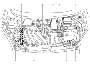
1. 2.
Headlight/turn signal switch (P. 2-23) Driver’s supplemental air bag /horn (P. 1-36, 2-26)
3. Meters and gauges (P. 2-3) 4. Windshield wiper/washer switch
(P. 2-21)
2-2 Instruments and controls
LIC2520
5. 6.
7. 8. 9.
Center vents (P. 4-14) Rear window and outside mirror (if so equipped) defroster switch (P. 2-22) Hazard warning flasher switch (P. 6-2) Climate controls (P. 4-15) Audio system (P. 4-31, 4-23)
10. Passenger’s supplemental air bag
(P. 1-36)
11. Side vents (P. 4-14) 12. Electronic outside rearview mirror
control switch (P.3-31)
13. Vehicle Dynamic Control (VDC) off
switch (P. 2-26)
14. Fuel-filler lid release lever (P. 3-26) 15. Hood release lever (P. 3-23) 16. Audio control switches (if so equipped)
(P.4-65)
17. Tilt steering (P. 3-29) 18.
Ignition switch/Push button ignition switch (if so equipped) (P. 5-8, P. 5-11)
19. Cruise control (if so equipped) (P.5-27) 20. Cup holders (P. 2-29) 21. Shift lever (P. 5-17) 22. Glove box (P. 2-27)
See the page number indicated in paren- theses for operating details.
METERS AND GAUGES
7.
Fuel gauge
Tachometer
1. 2. Speedometer 3.
Trip odometer reset switch/trip com- puter mode Instrument brightness control
4.
LIC2283
Type A
5. Continuously Variable Transmission
(CVT) / AT Automatic Transmission po- sition indicator (CVT / A/T models only) 6. Odometer/twin trip odometer/trip com-
puter
Instruments and controls 2-3
7. Continuously Variable Transmission
(CVT) / Manual Transmission shift indi- catorposition indicator Instrument brightness control
8.
LIC2146
Speedometer Trip odometer reset switch/trip com- puter mode
Tachometer Temperature gauge
1. 2. 3. Odometer/twin trip odometer/trip com-
Type B 5. 6.
puter Fuel gauge
4. 2-4 Instruments and controls
Type A
Type B
Type A
LIC2118
LIC2136
LIC2284
SPEEDOMETER AND ODOMETER Speedometer The speedometer indicates the vehicle speed.
Odometer/Twin trip odometer The odometer/twin trip odometer is displayed when the ignition switch is placed in the ON position. The odometer 䊊1 records the total distance the vehicle has been driven. The twin trip odometer 䊊2 records the distance of individual trips.
Instruments and controls 2-5
Type B
Type A
Type B
LIC2139
LIC2285
LPD2025
Loose fuel cap warning message Push the reset button 䊊A for more than 1 second to reset the LOOSE FUEL CAP warning mes- sage after the fuel cap has been tightened. For additional information see “Fuel-filler cap” in the “Pre-driving checks and adjustments” section of this manual.
→ Trip
Changing the display: Press the change button 䊊3 to change the dis- play as follows: → Odometer (ODO) → Trip Instant fuel consumption → Average fuel con- sumption → DTE (cruising range) → Odometer (ODO) Resetting the trip odometer: Press the change button 䊊3 for more than 1 sec- ond to reset the currently displayed trip odometer to zero.
2-6 Instruments and controls
Type A
Type B
Type A
LIC2436
LPD2128
LIC2107
Check tire pressure warning message (if so equipped) The CHECK TIRE PRES warning message is displayed when the low tire pressure warning light is illuminated and low tire pressure is de- tected. Check and adjust the tire pressure to the recommended COLD tire pressure shown on the Tire and Loading Information label. The CHECK TIRE PRES warning message can be turned off using the reset button 䊊A on the meter, the low tire pressure warning light will not be turned off. The low tire pressure warning light remains illu- minated until the tires are inflated to the recom-
mended COLD tire pressure. The CHECK TIRE PRES warning message is displayed each time the ignition switch is placed in the ON position as long as the low tire pressure warning light re- mains illuminated. For more information see “Low tire pressure warning light” in the “Instruments and controls” section, “Tire Pressure Monitoring System (TPMS)” in the “Starting and driving” section, and “Wheels and tires” in the “Mainte- nance and do-it-yourself” section of this Owner’s Manual.
TACHOMETER The tachometer indicates engine speed in revo- lutions per minute (rpm). Do not rev the engine into the red zone 䊊1 .
CAUTION
When engine speed approaches the red zone, shift to a higher gear or reduce en- gine speed. Operating the engine in the red zone may cause serious engine damage.
Instruments and controls 2-7
Type B
Type A
Type B
LIC2151
LIC2286
LIC2287
The located on the driver’s side of the vehicle.
indicates that the fuel-filler door is
FUEL GAUGE The gauge indicates 䊊A the approximate fuel level in the tank when the ignition switch is placed in the ON position. The gauge may move slightly during braking, turning, acceleration, or going up or down hills. Type A: The fuel level segments will blink when the amount of fuel in the tank is getting low. Type B: The low fuel warning light will turn on when the amount of fuel in the tank is getting low. Refill the fuel tank before the gauge regis- ters E (Empty).
2-8 Instruments and controls
CAUTION
● If the vehicle runs out of fuel, the
check engine light may come on. Refuel as soon as possible. After a few driving light should turn off. If trips, the the light remains on after a few driving trips, have the vehicle inspected by a NISSAN dealer.
● For additional information, see “Mal- function Indicator Light (MIL)” later in this section.
Type A
Type B
LIC2288
LIC2138
TRIP COMPUTER When the ignition switch is placed in the ON position, modes of the trip computer can be selected by pushing the trip computer change button 䊊A on the instrument panel located near the speedometer. The following modes can be selected in the display 䊊B : ● Instant fuel consumption ● Average fuel consumption ● Distance to empty
Instant fuel economy The instant fuel economy mode shows the instant fuel consumption. The display updates instantly when driving. Average fuel consumption The average fuel consumption mode shows the average fuel consumption since the last reset. Resetting is done by pushing the trip computer change button 䊊A for more than approximately 1 second.
Instruments and controls 2-9
Distance to empty The distance to empty mode provides you with an estimation of the distance that can be driven before refueling. The range is constantly being calculated, based on the amount of fuel in the fuel tank and the actual fuel consumption.
The distance to empty includes a low range warning feature: when the fuel level is low, the distance to empty is automatically selected and the digits blink in order to draw the driver’s atten- tion. Press the trip computer change button 䊊A if you wish to return to the mode that was selected before the warning occurred.
When the fuel level drops even lower, the dis- tance to empty will display (----). Trip computer reset Pushing the change button for more than 3 sec- onds will reset all modes except Trip A and dis- tance to empty (dte). SERVICE INTERVAL REMINDER (if so equipped) When the ignition switch is placed in the ON position, a wrench symbol and the distance to oil change information will illuminate on the display for approximately 5 seconds. The wrench symbol and distance to oil change switch to oil display 2-10 Instruments and controls
status. Then the oil display status switches to odometer and twin trip odometer/trip computer information mode that was displayed before the ignition switch was placed in the ACC, OFF or LOCK position. The oil level display status provides specific in- formation regarding your approximate engine oil level. If the oil level is sufficient, “Oil Good” is displayed for approximately 10 seconds. If the oil level is low, “Oil Lo” blinks for approximately 30 seconds in order to draw your attention to necessary ac- tion. Quickly push and release the trip computer change button 䊊A on the instrument panel lo- cated near the speedometer 䊊B during the “Oil Good” or “Oil Lo” mode to display an approxi- mate oil level indication. In case of low engine oil level, see “Engine oil” in the “Maintenance and do-it-yourself” section for the proper engine oil refilling procedure. Oil change schedule set up It is possible to adjust the interval distance to oil change by pushing the trip computer change button 䊊A on the instrument panel located near the speedometer 䊊B for 3 seconds while the wrench symbol and distance to oil change are displayed. The symbol and distance display will
start flashing and the display shows the current interval. Push the switch to increase the interval distance. Each step increases the interval dis- tance by 500 mi (1,000 km). The interval distance can be set up to 18,000 mi (30,000 km) after which the display returns to zero.
If no further action is made, the display returns to oil display status indication and the new interval is set.
If the interval distance is set to 0, the display will skip the distance to oil change information and wrench symbol display mode and will directly display the oil display status (“Oil Good” or “Oil Lo”). In order to return to the distance to oil change information and wrench symbol display mode, push the trip computer change button 䊊A on the instrument panel located near the speed- ometer 䊊B for approximately 3 seconds after the ignition switch has been turned to the ON posi- tion, and adjust the distance to oil change sched- ule as previously described.
See the Warranty Information & Maintenance Booklet for the appropriate interval distance to oil change.
CAUTION
● The oil level should be checked regu- larly. Operating with insufficient amount of oil level can damage the en- gine and such damage is not covered by the warranty.
● NISSAN recommends checking the oil
level every 3,000 mi (5,000 km).
Instruments and controls 2-11
WARNING/INDICATOR LIGHTS AND AUDIBLE REMINDERS
or
or
Anti-lock Braking System (ABS) warning light
Power steering warning light
Malfunction Indicator Light (MIL)
Brake warning light
Seat belt warning light and chime
Overdrive off indicator light (if so equipped)
Charge warning light
Shift P warning light (if so equipped)
Security indicator light (if so equipped)
Door open warning light
Supplemental air bag warning light
Side and headlight indicator light (green) (if so equipped)
Engine oil pressure warning light
Automatic Transmission (A/T)/Continuously Variable Transmission (CVT) position indicator light (if so equipped)
Slip indicator light
High temperature warning light (red)
Cruise main switch indicator light (if so equipped)
Turn signal/hazard indicator lights
or
Low fuel warning light
Engine start operation indicator (if so equipped)
Vehicle Dynamic Control (VDC) off indicator light
Low tire pressure warning light (if so equipped)
Front passenger air bag status light
NISSAN Intelligent Key® warning light (if so equipped)
High beam indicator light (blue)
2-12 Instruments and controls
CHECKING BULBS With all doors closed, apply the parking brake and place the ignition switch in the ON position without starting the engine. The following lights will come on:
or
If equipped, the following lights come on briefly and then go off:
or
(red),
or
SPORT, If any light fails to come on, it may indicate a burned-out bulb or an open circuit in the electrical system. Have the system repaired promptly. WARNING LIGHTS
or
Anti-lock Braking System (ABS) warning light
When the ignition switch is placed in the ON position, the Anti-lock Braking System (ABS) warning light illuminates and then turns off. This indicates the ABS is operational.
If the ABS warning light illuminates while the engine is running or while driving, it may indicate the ABS is not functioning properly. Have the system checked by a NISSAN dealer.
If an ABS malfunction occurs, the anti-lock func- tion is turned off. The brake system then operates normally, but without anti-lock assistance. See “Brake system” in the “Starting and driving” sec- tion.
or
Brake warning light
This light functions for both the parking brake and the foot brake systems. Parking brake indicator
When the ignition switch is placed in the ON position, the light comes on when the parking brake is applied. Low brake fluid warning light When the ignition switch is placed in the ON position, the light warns of a low brake fluid level. If the light comes on while the engine is running with the parking brake not applied, stop the ve- hicle and perform the following: 1. Check the brake fluid level. Add brake fluid as necessary. See “Brake fluid” in the “Main- tenance and do-it-yourself” section of this manual.
2.
If the brake fluid level is correct, have the warning system checked by a NISSAN dealer.
WARNING
● Your brake system may not be working properly if the warning light is on. Driv- ing could be dangerous. If you judge it to be safe, drive carefully to the nearest service station for repairs. Otherwise, have your vehicle towed because driv- ing it could be dangerous.
● Pressing the brake pedal with the en- gine stopped and/or a low brake fluid level may increase your stopping dis- tance and braking will require greater pedal effort as well as pedal travel.
● If the brake fluid level
is below the MINIMUM or MIN mark on the brake fluid reservoir, do not drive until the brake system has been checked at a NISSAN dealer.
Instruments and controls 2-13
Anti-lock Braking System (ABS) warning indicator
When the parking brake is released and the brake fluid level is sufficient, if both the brake warning light and the Anti-lock Braking System (ABS) warning light illuminate, it may indicate the ABS is not functioning properly. Have the brake system checked, and if necessary, repaired by a NISSAN dealer promptly. Avoid high-speed driv- ing and abrupt braking. See “Anti-lock Braking System (ABS) warning light” in this section.
Charge warning light
If this light comes on while the engine is running, it may indicate the charging system is not func- tioning properly. Turn the engine off and check the drive belt. If the belt is loose, broken, missing, or if the light remains on, see a NISSAN dealer immediately.
CAUTION
Do not continue driving if the drive belt is loose, broken or missing.
Door open warning light
This light comes on when any of the doors are not closed securely while the ignition switch is placed in the ON position. 2-14 Instruments and controls
Engine oil pressure warning light
This light warns of low engine oil pressure. If the light flickers or comes on during normal driving, pull off the road in a safe area, stop the engine immediately and call a NISSAN dealer or other authorized repair shop. The engine oil pressure warning light is not designed to indicate a low oil level. Use the dipstick to check the oil level. See “Engine oil” in the “Maintenance and do-it-yourself” section of this manual.
CAUTION
Running the engine with the engine oil pressure warning light on could cause se- rious damage to the engine almost imme- diately. Such damage is not covered by warranty. Turn off the engine as soon as it is safe to do so.
High temperature warning light
When the ignition switch is placed in the ON position, the high temperature warning light illu- minates and then turns off. This indicates that the high temperature sensor in the engine coolant system is operational.
CAUTION
If the high temperature warning light illu- minates while the engine is running, it may indicate the engine temperature is extremely high. Stop the vehicle safely as soon as possible. If the vehicle is over- heated, continuing vehicle operation may seriously damage the engine. See “If your vehicle overheats” in the “In case of emer- gency” section.
or
Low fuel warning light
This light comes on when the fuel level in the fuel tank is getting low. Refuel as soon as it is conve- nient, preferably before the fuel gauge reaches E (Empty). There will be a small reserve of fuel in the tank when the fuel gauge reaches E (Empty), showing no more fuel bars.
Low tire pressure warning light (if so equipped)
Your vehicle is equipped with a Tire Pressure Monitoring System (TPMS) that monitors the tire pressure of all tires except the spare. The low tire pressure warning light warns of low tire pressure or indicates that the TPMS is not functioning properly.
After the ignition switch is placed in the ON position, this light illuminates for about 1 second and turns off. Low tire pressure warning: If the vehicle is being driven with low tire pressure, the warning light will illuminate. A CHECK TIRE PRES (pressure) warning message is also displayed in the odometer. When the low tire pressure warning light illuminates, you should stop and adjust the tire pressure of all 4 tires to the recom- mended COLD tire pressure shown on the Tire and Loading Information label located in the driver’s door opening. The low tire pressure warning light does not automati- cally turn off when the tire pressure is ad- justed. After the tire is inflated to the rec- ommended pressure, the vehicle must be driven at speeds above 16 MPH (25 km/h) to activate the TPMS and turn off the low tire pressure warning light. Use a tire pres- sure gauge to check the tire pressure.
The low tire pressure warning light remains illu- minated until the tires are inflated to the recom- mended COLD tire pressure. The CHECK TIRE PRES warning message is displayed each time the ignition switch is placed in the ON position as long as the low tire pressure warning light re- mains illuminated. For additional information, see ⬙Check tire pres- sure warning message⬙ in the ⬙Instruments and controls⬙ section and “Tire Pressure Monitoring System (TPMS)” in the “Starting and driving” section and in the “In case of emergency” sec- tion. TPMS malfunction:
If the TPMS is not functioning properly, the low tire pressure warning light will flash for approxi- mately 1 minute when the ignition switch is placed in the ON position. The light will remain on after the 1 minute. Have the system checked by a NISSAN dealer.
For additional information, see “Tire Pressure Monitoring System (TPMS)” in the “Starting and driving” section and “Tire pressure” in the “Main- tenance and do-it-yourself” section.
WARNING
● If the light does not illuminate with the ignition switch placed in the ON posi- tion, have the vehicle checked by a NISSAN dealer as soon as possible.
● If the light illuminates while driving, avoid sudden steering maneuvers or abrupt braking, reduce vehicle speed, pull off the road to a safe location and stop the vehicle as soon as possible. Driving with under-inflated tires may permanently damage the tires and in- crease the likelihood of tire failure. Se- rious vehicle damage could occur and may lead to an accident and could result in serious personal injury. Check the tire pressure for all four tires. Adjust the tire pressure to the recommended COLD tire pressure shown on the Tire and Loading Information label located in the driver’s door opening to turn the low tire pressure warning light OFF. If the light still comes on while driving after adjusting the tire pressure, a tire may be flat. If you have a flat tire, re- place it with a spare tire as soon as possible.
Instruments and controls 2-15
● When a spare tire is mounted or a wheel is replaced the TPMS will not function and the low tire pressure warning light will flash for approximately 1 minute. The light will remain on after 1 minute. Contact your NISSAN dealer as soon as possible for tire replacement and/or system resetting.
● Replacing tires with those not originally specified by NISSAN could affect the proper operation of the TPMS.
CAUTION
● The TPMS is not a substitute for the regular tire pressure check. Be sure to check the tire pressure regularly.
● If the vehicle is being driven at speeds of less than 16 MPH (25 km/h), the TPMS may not operate correctly.
● Be sure to install the specified size of
tires to the 4 wheels correctly.
2-16 Instruments and controls
NISSAN Intelligent Key® warning light (if so equipped)
After the ignition switch is placed in the “ON” position, this light comes on for about 2 seconds and then turns off. This light illuminates or blinks as follows: ● The light blinks in yellow when the door is closed with the Intelligent Key left outside the vehicle and the ignition switch in the “ACC” or “ON” position. Make sure that the Intelligent Key is inside the vehicle.
● The light blinks in green when the Intelligent Key battery is running out of power. Replace the battery with a new one. See “Battery” in the “Maintenance and do-it-yourself” sec- tion.
● The light illuminates in yellow when it warns of a malfunction with the electrical steering lock system or the Intelligent Key system.
If the warning light illuminates in yellow while the engine is stopped, it may be impossible to free the steering lock or to start the engine. If the light comes on while the engine is running, you can drive the vehicle. However in these cases, contact a NISSAN dealer for repair as soon as possible. See “NISSAN Intelligent Key®” in the “Pre- driving checks and adjustments” section.
Power steering warning light
WARNING
● If the engine is not running or is turned off while driving, the power assist for the steering will not work. Steering will be harder to operate.
● When the power steering warning light illuminates with the engine running, there will be no power assist for the steering. You will still have control of the vehicle but the steering will be harder to operate. Have the power steering system checked by a NISSAN dealer.
When the ignition switch is placed in the ON position, the power steering warning light illumi- nates. After starting the engine, the power steer- ing warning light turns off. This indicates the power steering system is operational. If the power steering warning light illuminates while the engine is running, it may indicate the power steering system is not functioning properly and may need servicing. Have the power steering system checked by a NISSAN dealer.
When the power steering warning light illumi- nates with the engine running, there will be no power assist for the steering but you will still have control of the vehicle. At this time, greater steer- ing effort is required to operate the steering wheel, especially in sharp turns and at low speeds.
See “Power steering” in the “Starting and driving” section.
Seat belt warning light and chime
The light and chime remind you to fasten your seat belts. The light illuminates whenever the ignition switch is placed in the ON or START position and remains illuminated until the driver’s seat belt is fastened. At the same time, the chime sounds for about 6 seconds unless the driver’s seat belt is securely fastened.
The seat belt warning light may also illuminate if the front passenger’s seat belt is not fastened when the front passenger’s seat is occupied . For 7 seconds after the ignition switch is placed in the ON position, the system does not activate the warning light for the front passenger. Refer to “Seat belts” in the “Safety—Seats, seat belts and supplemental restraint system” section for precautions on seat belt usage.
Shift P warning light (if so equipped)
This light blinks red and the key reminder chime sounds if the shift lever is in any position other than P (Park) and the ignition switch is in the OFF position. Return the shift lever to P (Park) with the ignition switch in the OFF position and the light will turn off. Place the ignition switch in the LOCK position and the chime will turn off.
Supplemental air bag warning light
When the ignition switch is placed in the ON or START position, the supplemental air bag warn- ing light illuminates for about 7 seconds and then turns off. This means the system is operational.
If any of the following conditions occur, the front air bag, side air bag, curtain air bag, and preten- sioner seat belt systems need servicing and your vehicle must be taken to a NISSAN dealer: ● The supplemental air bag warning light re-
mains on after approximately 7 seconds.
● The supplemental air bag warning light
flashes intermittently.
● The supplemental air bag warning light does
not come on at all.
Unless checked and repaired, the supplemental restraint system (air bag system) and/or the pre- tensioners may not function properly. For addi- tional details see “Supplemental restraint sys- tem” in the “Safety—Seats, seat belts and supplemental restraint system” section of this manual.
WARNING
If the supplemental air bag warning light is on, it could mean that the front air bag, side air bag, curtain air bag systems and/or pretensioner systems will not op- erate in an accident. To help avoid injury to yourself or others, have your vehicle checked by a NISSAN dealer as soon as possible.
INDICATOR LIGHTS
Automatic Transmission (A/T)/Continuously Variable Transmission (CVT) position indicator light (if so equipped)
When the ignition switch is placed in the ON position, this indicator light shows the shift lever position. See “Driving the vehicle” in the “Starting and driving” section of this manual.
Instruments and controls 2-17
Cruise main switch indicator light (if so equipped)
The light comes on when the cruise control main switch is pushed. The light goes out when the main switch is pushed again. When the cruise main switch indicator light comes on, the cruise control system is operational.
Engine start operation indicator (if so equipped)
For vehicles equipped with push button ignition this indicator illuminates when the ignition switch is in the LOCK, OFF, ACC or ON position with the shift lever in the P (Park) position.
This indicator means that the engine will start by pushing the push-button ignition switch with the brake pedal depressed.
Front passenger air bag status light
The front passenger air bag status light ( will be lit and the passenger front air bag will be OFF depending on how the front passenger seat is being used.
For front passenger air bag status light operation, see “Front passenger air bag and status light” in 2-18 Instruments and controls
the “Safety — Seats, seat belts and supplemental restraint system” section of this manual. High beam indicator light (blue)
This blue light comes on when the headlight high beams are on and goes out when the low beams are selected.
The high beam indicator light also comes on when the passing signal is activated.
Malfunction Indicator Light (MIL)
If this indicator light comes on steady or blinks while the engine is running, it may indicate a potential emission control malfunction.
may also come on steady if the fuel- The filler cap is loose or missing, or if the vehicle runs out of fuel. Check to make sure the fuel-filler cap is installed and closed tightly, and that the vehicle has at least 3 gal (11.4 L) of fuel in the fuel tank.
light should After a few driving trips, the turn off if no other potential emission control system malfunction exists. If this indicator light comes on steady for 20 sec- onds and then blinks for 10 seconds when the engine is not running, it indicates that the vehicle
is not ready for an emission control system inspection/maintenance test. See “Readiness for inspection/maintenance (I/M) test” in the “Tech- nical and consumer information” section of this manual. Operation
The Malfunction Indicator Light will come on in one of two ways: ● Malfunction Indicator Light on steady — An emission control system malfunction has been detected. Check the fuel-filler cap. If the LOOSE FUEL CAP warning message is displayed in the odometer, and the fuel-filler cap is loose or missing, tighten or install the cap and continue to drive the vehicle. light should turn off after a few The driving trips. If the light does not turn off after a few driving trips, have the vehicle inspected by a NISSAN dealer. You do not need to have your vehicle towed to the dealer.
● Malfunction Indicator Light blinking — An engine misfire has been detected which may damage the emission control system. To re- duce or avoid emission control system dam- age: – do not drive at speeds above 45 MPH
(72 km/h).
– avoid hard acceleration or deceleration.
– avoid steep uphill grades.
– if possible, reduce the amount of cargo
being hauled.
The Malfunction Indicator Light may stop blinking and come on steady. Have the vehicle inspected by a NISSAN dealer. You do not need to have your vehicle towed to the dealer.
CAUTION
Continued vehicle operation without hav- ing the emission control system checked and repaired as necessary could lead to poor driveability, reduced fuel economy, and possible damage to the emission con- trol system.
Overdrive OFF indicator light (A/T / CVT models) (if so equipped)
The overdrive off indicator light illuminates when the overdrive off mode is selected.
For additional information, see “Driving the ve- hicle” in the “Starting and driving” section of this manual.
Security indicator light (if so equipped)
Turn signal/hazard indicator lights
This light blinks when the ignition switch is in the OFF, LOCK or ACC position. The blinking secu- rity indicator light indicates that the security sys- tems equipped on the vehicle are operational.
For additional tems” later in this section.
information, see “Security sys-
Side light and headlight indicator light (green) (if so equipped)
The side light and headlight indicator light illumi- nates when the side light or headlight position is selected. See “Headlight and turn signal switch” later in this section for further details.
Slip indicator light
This indicator will blink when the VDC system or the traction control system is operating, thus alerting that the vehicle is nearing its traction limits. The road surface may be slippery.
The appropriate light flashes when the turn signal switch is activated.
Both lights flash when the hazard switch is turned on.
Vehicle Dynamic Control (VDC) off indicator light
This indicator light comes on when the Vehicle Dynamic Control off switch is pushed to OFF. This indicates the Vehicle Dynamic Control sys- tem is not operating.
Push the Vehicle Dynamic Control off switch again or restart the engine and the system will operate normally. See “Vehicle Dynamic Control (VDC) system” in the “Starting and driving” sec- tion of this manual.
The Vehicle Dynamic Control light also comes on when you place the ignition switch in the ON position. The light will turn off after about 2 sec- onds if the system is operational. If the light stays indicator on or comes on along with the light while you are driving, have the Vehicle Dy- namic Control system checked by a NISSAN dealer.
Instruments and controls 2-19
NISSAN Intelligent Key® door buzzer (if so equipped) The Intelligent Key door buzzer sounds if any one of the following improper operations is found. ● The ignition switch is not returned to the
LOCK position when locking the doors.
● The Intelligent Key is left inside the vehicle
when locking the doors.
● The Intelligent Key is taken outside the ve-
hicle when operating the vehicle.
● Any doors are not closed securely when
locking the doors.
When the buzzer sounds, be sure to check both the vehicle and the Intelligent Key. See “NISSAN Intelligent Key®” in the “Pre-driving checks and adjustments” section. Parking brake reminder chime A chime sounds if the parking brake is set and the vehicle is driven. The chime will stop if the parking brake is released or the vehicle speed returns to zero.
SECURITY SYSTEM
NISSAN VEHICLE IMMOBILIZER SYSTEM (if so equipped) The NISSAN Vehicle Immobilizer System will not allow the engine to start without the use of a registered key. If the engine fails to start using a registered key (for example, when interference is caused by another registered key, an automated toll road device or automatic payment device on the key ring), restart the engine using the following pro- cedures: 1. Leave the ignition switch in the ON position
for approximately 5 seconds.
2. Turn the ignition switch to the OFF or LOCK position, and wait approximately 10 sec- onds.
3. Repeat steps 1 and 2. 4. Restart the engine while holding the device (which may have caused the interference) separate from the registered key.
If the no start condition re-occurs, NISSAN rec- ommends placing the registered key on a sepa- rate key ring to avoid interference from other devices.
While the Vehicle Dynamic Control system is operating, you might feel slight vibration or hear the system working when starting the vehicle or accelerating, but this is normal. AUDIBLE REMINDERS Brake pad wear warning The disc brake pads have audible wear warnings. When a disc brake pad requires replacement, it makes a high pitched scraping sound when the vehicle is in motion, whether or not the brake pedal is depressed. Have the brakes checked as soon as possible if the warning sound is heard. Key reminder chime A chime sounds if the driver’s door is opened while the key is left in the ignition switch. Remove the key and take it with you when leaving the vehicle. Light reminder chime With the ignition switch placed in the OFF posi- tion, a chime sounds when the driver’s door is opened if the headlights or parking lights are on.
Turn the headlight control switch off before leav- ing the vehicle.
2-20 Instruments and controls
FCC Notice: For USA: This device complies with part 15 of the FCC Rules. Operation is subject to the fol- lowing two conditions; (1) This device may not cause harmful interference, and (2) this device must accept any interference re- ceived, including interference that may cause undesired operation of the device.
NOTE: Changes or modifications not expressly ap- proved by the party responsible for compli- ance could void the user’s authority to op- erate the equipment. For Canada: This device complies with RSS-210 of In- dustry Canada. Operation is subject to the following two conditions; (1) This device may not cause harmful interference, and (2) this device must accept any interference received, including interference that may cause undesired operation of the device.
WINDSHIELD WIPER AND WASHER SWITCH
LIC0474
LIC2153
Security indicator light This light blinks whenever the ignition switch is placed in the LOCK, OFF or ACC position. This function indicates the NISSAN Vehicle Im- mobilizer System is operational. If the NISSAN Vehicle Immobilizer System is mal- functioning, the light will remain on while the ignition switch is placed in the ON position. If the light still remains on and/or the en- gine will not start, see a NISSAN dealer for NISSAN Vehicle Immobilizer System ser- vice as soon as possible. Please bring all registered keys that you have when visiting your NISSAN dealer for service.
Type A SWITCH OPERATION The windshield wiper and washer operates when the ignition switch is in the ON position.
Push the lever down to operate the wiper at the following speed: 䊊1
Intermittent (INT) — intermittent operation can be adjusted by turning the knob toward 䊊A (Slower) or 䊊B (Faster). 䊊2
Low (LO) — continuous low speed operation 䊊3 High (HI) — continuous high speed opera-tion
Instruments and controls 2-21
CAUTION
● Do not operate the washer continuously
for more than 30 seconds.
● Do not operate the washer if the reser-
voir is empty.
● Do not fill the windshield-washer fluid reservoir with washer fluid concen- trates at full strength. Some methyl al- cohol based washer fluid concentrates may permanently stain the grille if spilled while filling the windshield- washer fluid reservoir.
● Pre-mix windshield-washer fluid con- centrates with water to the manufactur- er’s recommended levels before pour- ing the fluid into the windshield-washer fluid reservoir. Do not use the windshield-washer to mix the windshield-washer fluid con- centrate and water.
fluid reservoir
REAR WINDOW AND OUTSIDE MIRROR (if so equipped) DEFROSTER SWITCH
LIC2116
To defrost the rear window glass, start the engine and push the rear window defroster switch on. The rear window defroster indicator light on the switch comes on. Push the switch again to turn the defroster off. The rear window defroster automatically turns off after approximately 15 minutes.CAUTION
When cleaning the inner side of the rear window, be careful not to scratch or dam- age the rear window defroster.
LIC2131
Type B
Push the lever up 䊊4 to have one sweep opera- tion (MIST ) of the wiper. Pull the lever toward you 䊊5
to operate the washer. The wiper will also operate several times.WARNING
In freezing temperatures the washer solu- tion may freeze on the windshield and obscure your vision which may lead to an accident. Warm the windshield with the defroster before you wash the windshield.
2-22 Instruments and controls
HEADLIGHT AND TURN SIGNAL SWITCH
LIC2127
WIC1509
Type A
HEADLIGHT CONTROL SWITCH Lighting 䊊1 When turning the switch to the
posi- tion, the front parking, tail, license plate and instrument panel lights come on. 䊊2 When turning the switch to the
posi- tion, the headlights come on and all the other lights remain on.
Type B
CAUTION
Use the headlights with the engine run- ning to avoid discharging the vehicle battery.
LIC2128
Headlight beam select 䊊1 To select the high beam function, push the lever forward. The high beam lights come on and the
light illuminates.
䊊2 Pull the lever back to select the low beam. 䊊3 Pulling and releasing the lever flashes the
headlight high beams on and off.
Battery saver system If the ignition switch is placed in the OFF position while the headlight switch is in the or a period of time.
position, the headlights will turn off after
Instruments and controls 2-23
CAUTION
WARNING
When the daytime running light system is active, tail lights on your vehicle are not on. It is necessary at dusk to turn on your headlights. Failure to do so could cause an accident injuring yourself and others.
Even though the battery saver feature au- tomatically turns off the headlights after a period of time, you should turn the head- light switch to the OFF position when the engine is not running to avoid discharging the vehicle battery.
DAYTIME RUNNING LIGHT SYSTEM (Canada only) The headlights automatically illuminate at a re- duced intensity when the engine is started with the parking brake released. The daytime running lights operate with the headlight switch in the position. Turn the OFF position or in the position for full headlight switch to the illumination when driving at night.
If the parking brake is applied before the engine is started, the daytime running lights do not illumi- nate. The daytime running lights illuminate when the parking brake is released. The daytime run- ning lights will remain on until the ignition switch is placed in the OFF position.
2-24 Instruments and controls
Type A
LIC2289
position.
INSTRUMENT BRIGHTNESS CONTROL The instrument brightness control operates when the headlight control switch is in the or Type A: Turn the control 䊊A to adjust the bright- ness of instrument panel lights when driving at night. Type B: Press the control 䊊A to adjust the bright- ness of instrument panel lights when driving at night.
Type B
LIC2137
WIC1512
TURN SIGNAL SWITCH Turn signal 䊊1 Move the lever up or down to signal the turning direction. When the turn is com- pleted, the turn signal cancels automatically.
Lane change signal 䊊2 To signal a lane change, move the lever up or down to the point where the indicator light begins to flash, but the lever does not latch. The turn signal will flash three times automati- cally.
WIC1513
FOG LIGHT SWITCH (if so equipped) To turn the fog lights on, turn the headlight switch to the position, then turn the fog light switch to the To turn the fog lights off, turn the fog light switch to the OFF position. The headlights must be on and the low beams selected for the fog lights to operate. The fog lights automatically turn off when the high beam headlights are selected.position.
Instruments and controls 2-25
HORN
VEHICLE DYNAMIC CONTROL (VDC) OFF SWITCH
Push the VDC OFF switch again or restart the engine to turn on the system. See “Vehicle Dy- namic Control (VDC) system” in the “Starting and driving” section.
LIC2163
To sound the horn, push near the horn icon on the steering wheel.WARNING
Do not disassemble the horn. Doing so could affect proper operation of the supplemental front air bag system. Tam- pering with the supplemental front air bag system may result in serious personal injury.
LIC1548
The vehicle should be driven with the Vehicle Dynamic Control (VDC) system on for most driv- ing conditions. If the vehicle is stuck in mud or snow, the VDC system reduces the engine output to reduce wheel spin. The engine speed will be reduced even if the accelerator is depressed to the floor. If maximum engine power is needed to free a stuck vehicle, turn the VDC system off. To turn off the VDC system, push the VDC OFF switch. Theindicator will come on.
2-26 Instruments and controls
● Push the plug in as far as it will go. If good contact is not made, the plug may overheat or the internal temperature fuse may open.
● When not in use, be sure to close the cap. Do not allow water or any other liquid to contact the outlet.
POWER OUTLET
The power outlet is for powering electrical acces- sories such as cellular telephones. The outlet is rated at 12 volt, 120 W (10A) maximum.
CAUTION
● The outlet and plug may be hot during
or immediately after use.
● Only certain power outlets are designed for use with a cigarette lighter unit. Do not use any other power outlet for an accessory lighter. See your NISSAN dealer for additional information.
● Do not use with accessories that exceed a 12 volt, 120 W (10A) power draw. Do not use double adapters or more than one electrical accessory.
● Use power outlets with the engine run- ning to avoid discharging the vehicle battery.
LIC2156
● Avoid using power outlets when the air conditioner (if so equipped), headlights or so equipped) is on.
rear window defroster
(if
● Before inserting or disconnecting a plug, be sure the electrical accessory being used is turned OFF.
Instruments and controls 2-27
STORAGE
MAP POCKETS
LIC2157
LIC1328
SEATBACK POCKET (if so equipped) The seatback pocket is located on the back of the passenger’s seat. The pocket can be used to store maps.STORAGE TRAYS
LIC2113
WARNING
Do not place sharp objects in the trays to help prevent injury in an accident or sud- den stop.
2-28 Instruments and controls
LIC2159
LIC2158
LIC2162
CUP HOLDERS
Front
CAUTION
● Avoid abrupt starting and braking when the cup holder is being used to prevent spilling the drink. If the liquid is hot, it can scald you or your passenger.
● Use only soft cups in the cup holder. Hard objects can injure you in an accident.
Bottle holder
CAUTION
● Do not use bottle holder for any other objects that could be thrown about in the vehicle and possibly injure people during sudden braking or an accident. ● Do not use bottle holder for open liquid
containers.
Rear
Instruments and controls 2-29
WINDOWS
POWER WINDOWS (if so equipped)
WARNING
● Make sure that all passengers have their hands, etc. inside the vehicle while it is in motion and before closing the windows. Use the window lock switch to prevent unexpected use of the power windows.
● Do not leave children unattended inside the vehicle. They could unknowingly ac- tivate switches or controls and become trapped in a window. Unattended chil- dren could become involved in serious accidents.
The power windows operate when the ignition switch is placed in the ON position, or for a period of time after the ignition switch is placed in the OFF position. If the driver’s or passenger’s door is opened during this period of time, the power to the windows is canceled.
WIC0872
1. Window lock button 2. 3. 4. 5. 6.
Power door lock switch Front passenger’s side window switch Right rear passenger’s window switch Left rear passenger’s window switch Driver’s side automatic switch
GLOVE BOX Open the glove box by pulling the handle.
LIC2160
WARNING
Keep glove box lid closed while driving to help prevent injury in an accident or a sudden stop.
2-30 Instruments and controls
Driver’s side power window switch The driver’s side control panel is equipped with switches to open or close the front and rear passenger windows. To open a window, push the switch and hold it down. To close a window, pull the switch and hold it up. To stop the opening or closing function at any time, simply release the switch.
LIC0718
LIC0718
Front passenger’s power window switch The passenger’s window switch operates only the corresponding passenger’s window. To open the window, push the switch and hold it down 䊊1 . To close the window, pull the switch up 䊊2 .
Rear power window switch The rear power window switches open or close only the corresponding windows. To open the window, push the switch and hold it down 䊊1 . To close the window, pull the switch up 䊊2 . Locking passengers’ windows When the window lock button is depressed, only the driver’s side window can be opened or closed. Push it again to cancel the window lock function.
Instruments and controls 2-31
INTERIOR LIGHT
LIC0410
Automatic operation To fully open a window equipped with automatic operation, press the window switch down to the second detent and release it; it need not be held. The window automatically opens all the way. To stop the window, lift the switch up while the window is opening.
WIC0263
MANUAL WINDOWS (if so equipped) The side windows can be opened or closed by turning the hand crank on each door.SIC2063A The interior light has a three-position switch and operates regardless of ignition switch position. When the switch is in the ON position 䊊1 , the interior lights illuminate, regardless of door posi- tion. The lights will go off after a period of time unless the ignition switch is placed in the ACC or ON position.
2-32 Instruments and controls
When the switch is in the DOOR position 䊊2 , the interior lights will stay on for a period of time when: ● The doors are unlocked by the keyfob (if so equipped), a key or the power door lock switch (if so equipped) while all doors are closed and the ignition switch is placed in the OFF position.
● The driver’s door is opened and then closed while the key is removed from the ignition switch.
● The key is removed from the ignition switch
while all doors are closed.
The lights will turn off while the timer is activated when: ● The driver’s door is locked by the keyfob (if so equipped), a key, or the power door lock switch (if so equipped).
● The ignition switch is placed in the ON po-
sition.
When the switch is in the OFF position 䊊3 , the interior lights do not illuminate, regardless of door position.
The lights will turn off automatically after a period of time while doors are open to prevent the bat- tery from becoming discharged.
MAP LIGHT (if so equipped)
CAUTION
Do not use for extended periods of time with the engine stopped. This could result in a discharged battery.
LIC2126
The map light has a three-position switch and operates regardless of ignition switch position. When the switch is in the ON position 䊊3 , the map light illuminates, regardless of door position. The light will go off after a period of time unless the ignition switch is placed in the ACC or ON position. When the switch is in the DOOR position 䊊2 , the map light will stay on for a period of time when: ● The doors are unlocked by the keyfob (if so equipped), a key or the power door lock switch while all doors are closed and the ignition switch is placed in the OFF position. Instruments and controls 2-33
TRUNK LIGHT
The light illuminates when the trunk lid is opened. When the trunk lid is closed, the light goes off. For bulb replacement procedures, refer to “Exte- rior and interior lights” in the “Maintenance and do-it-yourself” section of this manual.
● The driver’s door is opened and then closed while the key is removed from the ignition switch.
● The key is removed from the ignition switch
while all doors are closed.
The light will turn off while the timer is activated when: ● The driver’s door is locked by the keyfob (if so equipped), a key, or the power door lock switch.
● The ignition switch is placed in the ON po-
sition.
When the switch is in the OFF position 䊊1 , the map light does not illuminate, regardless of door position. The light will turn off automatically after a period of time while doors are open to prevent the bat- tery from becoming discharged.
CAUTION
Do not use for extended periods of time with the engine stopped. This could result in a discharged battery.
2-34 Instruments and controls
3 Pre-driving checks and adjustments
Keys . . . . . . . . . . . . . . . . . . . . . . . . . . . . . . . . . . . . . . . . . . . . . 3-2
NISSAN Intelligent Key® (if so equipped) . . . . . . . . . 3-3
NISSAN vehicle immobilizer system keys (if so equipped) . . . . . . . . . . . . . . . . . . . . . . . . . . . . . . . . 3-4
Doors . . . . . . . . . . . . . . . . . . . . . . . . . . . . . . . . . . . . . . . . . . . . 3-5
Locking with key. . . . . . . . . . . . . . . . . . . . . . . . . . . . . . . . 3-5
Locking with inside lock knob . . . . . . . . . . . . . . . . . . . . 3-6
Locking with power door lock switch (if so equipped) . . . . . . . . . . . . . . . . . . . . . . . . . . . . . . . . 3-6
Automatic door locks (if so equipped). . . . . . . . . . . . . 3-7
Child safety rear door lock . . . . . . . . . . . . . . . . . . . . . . . 3-7
Remote keyless entry system (if so equipped). . . . . . . . . 3-8
How to use remote keyless entry system . . . . . . . . . . 3-9
NISSAN Intelligent Key® (if so equipped) . . . . . . . . . . . 3-11
Operating range. . . . . . . . . . . . . . . . . . . . . . . . . . . . . . . 3-13
Door locks/unlocks precaution . . . . . . . . . . . . . . . . . . 3-14
NISSAN Intelligent Key® Operation . . . . . . . . . . . . . 3-14
How to use the remote keyless entry function . . . . . . . . . . . . . . . . . . . . . . . . . . . . . . . . . . . . . . 3-17
Warning lights and audible reminders . . . . . . . . . . . . 3-20Warning signals . . . . . . . . . . . . . . . . . . . . . . . . . . . . . . . 3-21
Troubleshooting guide . . . . . . . . . . . . . . . . . . . . . . . . . 3-22
Hood . . . . . . . . . . . . . . . . . . . . . . . . . . . . . . . . . . . . . . . . . . . 3-23
Trunk lid . . . . . . . . . . . . . . . . . . . . . . . . . . . . . . . . . . . . . . . . . 3-24
Key operation . . . . . . . . . . . . . . . . . . . . . . . . . . . . . . . . . 3-24
Opening the trunk lid. . . . . . . . . . . . . . . . . . . . . . . . . . . 3-24
Opener operation (if so equipped). . . . . . . . . . . . . . . 3-25
Interior trunk lid release . . . . . . . . . . . . . . . . . . . . . . . . 3-25
Fuel-filler door . . . . . . . . . . . . . . . . . . . . . . . . . . . . . . . . . . . 3-26
Opener operation. . . . . . . . . . . . . . . . . . . . . . . . . . . . . . 3-26
Fuel-filler cap . . . . . . . . . . . . . . . . . . . . . . . . . . . . . . . . . 3-26
Steering wheel . . . . . . . . . . . . . . . . . . . . . . . . . . . . . . . . . . . 3-29
Tilt operation . . . . . . . . . . . . . . . . . . . . . . . . . . . . . . . . . . 3-29
Sun visors . . . . . . . . . . . . . . . . . . . . . . . . . . . . . . . . . . . . . . . 3-29
Vanity mirror (if so equipped). . . . . . . . . . . . . . . . . . . . 3-30
Card holder (driver’s side only) . . . . . . . . . . . . . . . . . . 3-30
Mirrors . . . . . . . . . . . . . . . . . . . . . . . . . . . . . . . . . . . . . . . . . . 3-30
Rearview mirror . . . . . . . . . . . . . . . . . . . . . . . . . . . . . . . 3-30
Outside mirrors . . . . . . . . . . . . . . . . . . . . . . . . . . . . . . . 3-31KEYS
A key number plate is supplied with your keys. Record the key number and keep it in a safe place (such as your wallet), not in the vehicle. If you lose your keys, see a NISSAN dealer for duplicates by using the key number. NISSAN does not record key numbers so it is very important to keep track of your key number plate. A key number is only necessary when you have lost all keys and do not have one to make a duplicate. If you still have a key, your NISSAN dealer can duplicate it.
SPA2342
Type A
1. Master key 2. Master key 3.
Key number plate
3-2 Pre-driving checks and adjustments
LPD2045
Type B—Remote keyless entry keyfob (if soequipped)
1. 2.
Integrated door lock keyfob Key number plate
CAUTION
Do not leave the ignition key inside the vehicle when you leave the vehicle.
A key number plate is supplied with your keys. Record the key number and keep it in a safe place (such as your wallet), not in the vehicle. If you lose your keys, see a NISSAN dealer for duplicates by using the key number. NISSAN does not record key numbers so it is very important to keep track of your key number plate. A key number is only necessary when you have lost all keys and do not have one to duplicate from. If you still have a key, your NISSAN dealer can duplicate it.
Never leave these keys in the vehicle.
As many as 4 Intelligent Keys can be registered and used with one vehicle. The new keys must be registered by a NISSAN dealer prior to use with the Intelligent Key system and NISSAN Vehicle Immobilizer System of your vehicle. Since the registration process requires erasing all memory in the Intelligent Key components when register- ing new keys, be sure to take all Intelligent Keys that you have to the NISSAN dealer.
CAUTION
Listed below are conditions or occur- rences which will damage the Intelligent Key: ● Do not allow the Intelligent Key, which contains electrical to come into contact with water or salt water. This could affect the system function.
components,
● Do not drop the Intelligent Key. ● Do not strike the Intelligent Key sharply
against another object.
● Do not change or modify the Intelligent
Key.
Pre-driving checks and adjustments 3-3
LPD2076
Two Intelligent Keys
1. 2. Mechanical keys (inside Intelligent
Keys) Key number plate
3. NISSAN INTELLIGENT KEY® (if so equipped) Your vehicle can only be driven with the Intelligent Keys which are registered to your vehicle’s Intel- ligent Key system components and NISSAN Ve- hicle Immobilizer System components.
● Wetting may damage the Intelligent Key. If the Intelligent Key gets wet, im- mediately wipe until it is completely dry. ● Do not place the Intelligent Key for an extended period in an area where tem- peratures exceed 140°F (60°C).
● Do not attach the Intelligent Key with a
key holder that contains a magnet.
● Do not place the Intelligent Key near equipment that produces a magnetic field, such as a TV, audio equipment and personal computers.
3-4 Pre-driving checks and adjustments
CAUTION
Always carry the mechanical key installed in the Intelligent Key slot.
NISSAN VEHICLE IMMOBILIZER SYSTEM KEYS (if so equipped) You can only drive your vehicle using the master keys which are registered to the NISSAN Vehicle Immobilizer System components in your vehicle. These keys have a transponder chip in the key head.
The master key can be used for all the locks. Never leave these keys in the vehicle.
Additional or replacement keys:
If you still have a key, the key number is not necessary when you need extra NISSAN Vehicle Immobilizer System keys. Your dealer can dupli- cate your existing key. As many as 5 NISSAN Vehicle Immobilizer System keys can be used with one vehicle. You should bring all NISSAN Vehicle Immobilizer System keys that you have to your NISSAN dealer for registration. This is be- cause the registration process will erase the memory of all key codes previously registered into the NISSAN Vehicle Immobilizer System. After the registration process, these components will only recognize keys coded into the NISSAN
SPA1951
Mechanical key The Intelligent Key contains the mechanical key.
To remove the mechanical key, release the lock knob on the back of the Intelligent Key.
To install the mechanical key, firmly insert it into the Intelligent Key until the lock knob returns to the lock position.
Use the mechanical key to lock or unlock the doors and trunk lid.
See “Doors” and “Trunk lid” later in this section.
DOORS
Vehicle Immobilizer System during registration. Any key that is not given to your dealer at the time of registration will no longer be able to start your vehicle.
When the doors are locked using one of the following methods, the doors can not be opened using the inside or outside door handles. The doors must be unlocked to open the doors.
CAUTION
WARNING
Do not allow the immobilizer system key, which contains an electrical transponder, to come into contact with water or salt water. This could affect system function.
● Always have the doors locked while driving. Along with the use of seat belts, this provides greater safety in the event of an accident by helping to prevent persons from being thrown from the vehicle. This also helps keep children and others from unintentionally open- ing the doors, and will help keep out intruders.
● Before opening any door, always look
for and avoid oncoming traffic.
● Do not leave children unattended inside the vehicle. They could unknowingly ac- tivate switches or controls. Unattended children could become involved in seri- ous accidents.
Driver’s side
LPD0349
LOCKING WITH KEY Manual (if so equipped) To lock a door, turn the key toward the front of the vehicle 䊊1 . To unlock, turn the key toward the rear of the vehicle 䊊2 .
Pre-driving checks and adjustments 3-5
LPD0483
Power (if so equipped) The power door lock system allows you to lock or unlock all doors at the same time. Turning the key toward the front 䊊1 of the vehicle locks all doors. Turning the key one time toward the rear 䊊2 of the vehicle unlocks that door. From that position, returning the key to neutral 䊊3 (where the key can only be removed and inserted) and turning it toward the rear again within 5 seconds unlocks all doors 䊊4 .
3-6 Pre-driving checks and adjustments
Inside lock
SPA2760
LOCKING WITH INSIDE LOCK KNOB To lock the door without the key, move the inside lock knob to the lock position 䊊1 , then close the door. To unlock the door without the key, move the inside lock knob to the unlock position 䊊2 .
WPD0381
LOCKING WITH POWER DOOR LOCK SWITCH (if so equipped) To lock all the doors without a key, push the door lock switch (driver’s or front passenger’s side) to the lock position 䊊1 . When locking the door this way, be certain not to leave the key inside the vehicle. To unlock all the doors without a key, push the door lock switch (driver’s or front passenger’s side) to the unlock position 䊊2 .
4. When activated, the hazard indicator will flash twice. When deactivated, the hazard indicator will flash once.
5. The ignition switch must be placed in the OFF and ON position again between each setting change.
When the automatic door unlock system is deac- tivated, the doors do not unlock when the ignition switch is placed in the OFF position (models with Intelligent Key system) or when the key is re- moved from the ignition switch (models without Intelligent Key system). To unlock the door manu- ally, use the inside lock knob or the power door lock switch (driver’s or front passenger’s side).
Lockout protection When the power door lock switch (driver’s or front passenger’s side) is moved to the lock position with the key in the ignition switch and any door open, all doors will lock and then unlock automatically. This helps to prevent the keys from being accidently locked inside the vehicle. AUTOMATIC DOOR LOCKS (if so equipped) ● All doors lock automatically when the vehicle
speed reaches 15 MPH (24 km/h).
● All doors unlock automatically when the ig- nition is placed in the OFF position (models with Intelligent Key system) or when the key is removed from the ignition switch (models without Intelligent Key system).
The automatic unlock function can be de- activated or activated. To deactivate or acti- vate the automatic door unlock system, perform the following procedure: 1. Close all doors. 2. Place the ignition switch in the ON position. 3. Within 20 seconds of performing Step 2, push and hold the power door lock switch to position (UNLOCK) for more than the 5 seconds.
SPA2037
CHILD SAFETY REAR DOOR LOCK Child safety locks help prevent the rear doors from being opened accidentally, especially when small children are in the vehicle. The child safety lock levers are located on the edge of the rear doors. When the lever is in the unlock position 䊊2 , the door can be opened from the outside or the inside. When the lever is in the LOCK position 䊊1 , the door can be opened only from the out- side.Pre-driving checks and adjustments 3-7
REMOTE KEYLESS ENTRY SYSTEM (if so equipped)
WARNING
● Radio waves could adversely affect electric medical equipment. Those who use a pacemaker should contact the electric medical equipment manufac- turer for the possible influences before use.
● The remote keyless entry keyfob trans- mits radio waves when the buttons are pressed. The FAA advises radio waves may affect aircraft navigation and com- munication systems. Do not operate the remote keyless entry keyfob while on an airplane. Make sure the buttons are not operated unintentionally when the unit is stored for a flight.
It is possible to lock/unlock all doors, turn the interior lights on, and activate the panic alarm by using the keyfob from outside the vehicle. Be sure to remove the key from the vehicle before locking the doors.
The keyfob can operate at a distance of approxi- mately 33 ft (10 m) from the vehicle. The effective distance depends on the conditions around the vehicle.
3-8 Pre-driving checks and adjustments
As many as 5 keyfobs can be used with one vehicle. For information concerning the purchase and use of additional keyfobs, contact a NISSAN dealer.
The keyfob will not function when: ● the battery is discharged ● the distance between the vehicle and the
keyfob is over 33 ft (10 m)
The panic alarm will not activate when the key is in the ignition switch.
CAUTION
Listed below are conditions or occur- rences which will damage the keyfob: ● Do not allow the keyfob, which contains electrical components, to come into contact with water or salt water. This could affect the system function.
● Do not drop the keyfob. ● Do not strike the keyfob sharply against
another object.
● Do not change or modify the keyfob. ● Wetting may damage the keyfob. If the keyfob gets wet, immediately wipe until it is completely dry.
● Do not place the keyfob for an extended period in an area where temperatures exceed 140°F (60°C).
● Do not attach the keyfob with a key
holder that contains a magnet.
● Do not place the keyfob near equipment that produces a magnetic field, such as a TV, audio equipment and personal computers.
If a keyfob is lost or stolen, NISSAN rec- ommends erasing the ID code of that key- fob. This will prevent the keyfob from un- authorized use to unlock the vehicle. For information regarding the erasing proce- dure, please contact a NISSAN dealer.
● When the
button is pressed with all doors locked, the hazard warning lights flash twice and the horn beeps once as a reminder the doors are already locked.
that
● If a door
is open and you press button, the doors will lock the but the horn will not beep and the hazard lights will not flash.
The horn may or may not beep. Refer to “Silenc- ing the horn beep feature” later in this section for details.
LPD2039
HOW TO USE REMOTE KEYLESS ENTRY SYSTEM Locking doors 1. Close all windows.
2. Remove the key from the ignition switch.
3. Close all doors.
4. Press the
button on the keyfob. All the doors lock. The hazard warning lights flash twice and the horn beeps once to indicate all doors are locked.
LPD2040
Unlocking doors
button on the keyfob once.
Press the ● Only the driver’s door unlocks. ● The hazard warning lights flash once if all doors are completely closed with the ignition switch in any position except the ON posi- tion.
● The interior light turns on and the light timer activates for a period of time when the inte- rior light switch is in the DOOR position with the ignition switch in any position except the ON position.
Pre-driving checks and adjustments 3-9
button on the keyfob once to
Using the interior light Press the turn on the interior lights. For additional information, refer to “Interior light” in the “Instruments and controls” section in this manual.
button on the keyfob again