- 2005 Nissan Quest Owners Manuals
- Nissan Quest Owners Manuals
- 2004 Nissan Quest Owners Manuals
- Nissan Quest Owners Manuals
- 1999 Nissan Quest Owners Manuals
- Nissan Quest Owners Manuals
- 1998 Nissan Quest Owners Manuals
- Nissan Quest Owners Manuals
- 2000 Nissan Quest Owners Manuals
- Nissan Quest Owners Manuals
- 2011 Nissan Quest Owners Manuals
- Nissan Quest Owners Manuals
- 1996 Nissan Quest Owners Manuals
- Nissan Quest Owners Manuals
- 2012 Nissan Quest Owners Manuals
- Nissan Quest Owners Manuals
- 2007 Nissan Quest Owners Manuals
- Nissan Quest Owners Manuals
- 2002 Nissan Quest Owners Manuals
- Nissan Quest Owners Manuals
- 2001 Nissan Quest Owners Manuals
- Nissan Quest Owners Manuals
- 2008 Nissan Quest Owners Manuals
- Nissan Quest Owners Manuals
- 2009 Nissan Quest Owners Manuals
- Nissan Quest Owners Manuals
- 1997 Nissan Quest Owners Manuals
- Nissan Quest Owners Manuals
- 2006 Nissan Quest Owners Manuals
- Nissan Quest Owners Manuals
- Download PDF Manual
-
fairly loud noise may be heard, followed by release of smoke. This smoke is not harmful and does not indicate a fire. Care should be taken not to inhale it, as it may cause irritation and choking. Those with a history of a breathing condition should get fresh air promptly.
Side air bags, along with the use of seat belts, help to cushion the impact force on the chest and pelvis of the front occupants. Curtain air bags help to cushion the impact force to the head of occupants in the front and rear (2nd and 3rd) outboard seating positions. They can help save lives and reduce serious injuries. However, an inflating side air bags and curtain air bags may cause abrasions or other injuries. Side air bags and curtain air bags do not provide restraint to the lower body.
The seat belts should be correctly worn and the driver and passenger seated upright as far as
practical away from the side air bag. Rear seat passengers should be seated as far away as practical from the door finishers and side roof rails. The side air bags and curtain air bags inflate quickly in order the occupants. Because of this, the force of the side air bags and curtain air bags inflating can increase the risk of injury if the occupant is too close to, or is against, these air bag modules during inflation. The side air bags will deflate quickly after the collision is over.
to help protect
The side air bags and curtain air bags operate only when the ignition switch is in the ON position.
After pushing the ignition switch to the ON position, the supplemental air bag warning light illuminates. The air bag warning light will turn off after about 7 seconds if the systems are operational.
WARNING
. Do not place any objects near the seatback of the front seats. Also, do not place any objects (an umbrella, bag, etc.) between the front door finisher and the front seat. Such objects may become dangerous projectiles and cause injury if side air bag inflates.
. Right after inflation, several side air bags and curtain air bag system components will be hot. Do not touch them; you may severely burn yourself.
. No unauthorized changes should be made to any components or wiring of side air bag and curtain air bags. This is to prevent damage to or accidental inflation of the side air bag and curtain air bag systems.
. Do not make unauthorized changes to your vehicle’s electrical system, suspension system or side panel. This could affect proper operation of the side air bag and curtain air bag systems.
Tampering with the air bag system may result in serious personal in- jury. For example, do not change the front seats by placing material near the seatback or by installing addi- tional trim material, such as seat covers, around the side air bags.
. Work around and on the side air bag and curtain air bag systems should be done by a NISSAN dealer. In- stallation of electrical equipment
Safety — Seats, seat belts and supplemental restraint system 1-57
Model "E52-D" EDITED: 2010/ 10/ 25
should also be done by a NISSAN dealer. The Supplemental Restraint System (SRS) wiring harnesses* should not be modified or discon- nected. Unauthorized electrical test equipment and probing devices should not be used on the side- impact air bag system.
The SRS wiring harness connectors are yellow and orange for easy identifica- tion.
When selling your vehicle, we request that you inform the buyer about the side air bag and curtain air bag systems and guide the buyer to the appropriate sections in this Owner’s Manual.
SEAT BELTS WITH PRETENSIONERS (front seats)
WARNING
The pretensioners cannot be reused after activation. They must be re- placed together with the retractor and buckle as a unit.
If the vehicle becomes involved in a collision but a pretensioner is not activated, be sure to have the pre- tensioner system checked and, if
necessary, replaced by a NISSAN dealer.
. No unauthorized changes should be made to any components or wiring of the pretensioner system. This is to prevent damage to or accidental activation of the pretensioners. Tampering with the pretensioner system may result in serious perso- nal injury.
. Work around and on the preten- sioner system should be done by a NISSAN dealer. Installation of elec- trical equipment should also be done by a NISSAN dealer. Un- authorized electrical test equipment and probing devices should not be used on the pretensioner system.
If you need to dispose of a preten- sioner or scrap the vehicle, contact a NISSAN dealer. Correct preten- sioner disposal procedures are set forth in the appropriate NISSAN Service Manual. Incorrect disposal procedures could cause personal injury.
The pretensioner system may activate with the supplemental air bag system in certain types of
1-58 Safety — Seats, seat belts and supplemental restraint system
Black plate (72,1)
collisions. Working with the seat belt retractor, it helps tighten the seat belt when the vehicle becomes involved in certain types of collisions, helping to restrain front seat occupants.
The pretensioner is encased with the seat belt retractor and buckle anchor. These seat belts are used the same way as conventional seat belts.
When a pretensioner activates, smoke is re- leased and a loud noise may be heard. The smoke is not harmful, and it does not indicate a fire. Care should be taken not to inhale it as it may cause irritation and choking. Those with a history of a breathing condition should get fresh air promptly.
After pretensioner activation, load limiters allow the seat belt to release webbing (if necessary) to reduce forces against the chest.
The supplemental air bag warning light is used to indicate malfunctions in the pretensioner system. (See “SUPPLEMENTAL AIR BAG WARNING LIGHT” later in this section for more details.) If the supplemental air bag warning light indicates there is a malfunction, have the system checked by a NISSAN dealer.
When selling your vehicle, we request that you inform the buyer about the pretensioner system and guide the buyer to the appropriate sections in this Owner’s Manual.
Model "E52-D" EDITED: 2010/ 10/ 25
Black plate (73,1)
operational.
If any of the following conditions occur, the front air bag, side air bag and curtain air bag and/or pretensioner systems need servicing:
The supplemental air bag warning light remains on approximately 7 seconds after the ignition switch is pushed to the ON position.
The supplemental air bag warning light flashes intermittently.
The supplemental air bag warning light does not come on at all.
Under these conditions, the front air bag, side air bags, and curtain air bags or pretensioner systems may not operate properly. They must be checked and repaired. Take your vehicle to the nearest NISSAN dealer.
WARNING
If the supplemental air bag warning light is on, it could mean that the front air bag, side air bag and curtain air bag and/or pretensioner systems will not operate in an accident. To help avoid injury to yourself or others, have your vehicle checked by a NISSAN dealer as soon as possible.
SSS1016
SPA1097
SUPPLEMENTAL AIR BAG WARNING LABELS Warning labels about the supplemental front- impact air bag system are placed in the vehicle as shown in the illustration.
SRS air bag The warning labels *1
surface of the sun visors.are located on the
SUPPLEMENTAL AIR BAG WARNING LIGHT The supplemental air bag warning light, display- in the instrument panel, monitors the ing circuits of the supplemental front-impact air bag, front seat-mounted side-impact supplemental air bag, roof-mounted curtain side-impact sup- plemental air bag, and seat belt pretensioner systems. The monitored circuits include the air bag systems, pretensioners and all related wiring.
When the ignition switch is in the ON position, the supplemental air bag warning light illumi- nates for about 7 seconds and then turns off. This means the SRS air bag systems are
Safety — Seats, seat belts and supplemental restraint system 1-59
Model "E52-D" EDITED: 2010/ 10/ 25
Black plate (74,1)
The front air bag, side air bag, curtain air bag and the pretensioner should be inspected by a NISSAN dealer if there is any damage to the front end or side portion of the vehicle.
If you need to dispose of a supple- mental air bag or pretensioner or scrap the vehicle, contact a NISSAN dealer. Correct supplemental air bag and pretensioner system dis- posal procedures are set forth in the appropriate NISSAN Service Man- ual. Incorrect disposal procedures could cause personal injury.
REPAIR AND REPLACEMENT PRO- CEDURE The front air bags, side air bags and curtain air bags and pretensioners are designed to activate on a one-time-only basis. As a reminder, unless it is damaged, the supplemental air bag warning light will remain illuminated after inflation has occurred. Repair and replacement of these systems should be done only by a NISSAN dealer.
When maintenance work is required on the vehicle, the front air bags, side air bags and curtain air bags, pretensioners and related parts should be pointed out to the person conducting the maintenance. The ignition switch should always be in the LOCK position when working under the hood or inside the vehicle.
WARNING
. Once a front air bag, side air bag or curtain air bag has inflated, the air bag module will not function again and must be replaced. Additionally, the activated pretensioner must also be replaced. The air bag mod- ule and pretensioner should be replaced by a NISSAN dealer. The air bag module and pretensioner system cannot be repaired.
1-60 Safety — Seats, seat belts and supplemental restraint system
Model "E52-D" EDITED: 2010/ 10/ 25
Black plate (75,1)
MEMO
Safety — Seats, seat belts and supplemental restraint system 1-61
Model "E52-D" EDITED: 2010/ 10/ 25
Black plate (7,1)
2 Instruments and controls
Cockpit. . . . . . . . . . . . . . . . . . . . . . . . . . . . . . . . . . . . . . . . . . . . . . . . . . . . . . . . . . . . 2-2
Instrument panel . . . . . . . . . . . . . . . . . . . . . . . . . . . . . . . . . . . . . . . . . . . . . . . . 2-3
Meters and gauges. . . . . . . . . . . . . . . . . . . . . . . . . . . . . . . . . . . . . . . . . . . . . 2-4
Meter/ring illumination and needle sweep. . . . . . . . . . . . . 2-4
Speedometer and odometer . . . . . . . . . . . . . . . . . . . . . . . . . . . . . 2-5
Tachometer. . . . . . . . . . . . . . . . . . . . . . . . . . . . . . . . . . . . . . . . . . . . . . . . . . . 2-6
Engine coolant temperature gauge . . . . . . . . . . . . . . . . . . . . . 2-6
Fuel gauge . . . . . . . . . . . . . . . . . . . . . . . . . . . . . . . . . . . . . . . . . . . . . . . . . . . 2-7
Compass (if so equipped) . . . . . . . . . . . . . . . . . . . . . . . . . . . . . . . . . . . . 2-7
Zone variation change procedure . . . . . . . . . . . . . . . . . . . . . . . 2-9
Warning/indicator lights and audible reminders . . . . . . . 2-10
Checking bulbs . . . . . . . . . . . . . . . . . . . . . . . . . . . . . . . . . . . . . . . . . . . 2-10
Warning lights . . . . . . . . . . . . . . . . . . . . . . . . . . . . . . . . . . . . . . . . . . . . . 2-10
Indicator lights. . . . . . . . . . . . . . . . . . . . . . . . . . . . . . . . . . . . . . . . . . . . . 2-15
Audible reminders . . . . . . . . . . . . . . . . . . . . . . . . . . . . . . . . . . . . . . . . 2-16
Dot matrix liquid crystal display. . . . . . . . . . . . . . . . . . . . . . . . . . . . 2-17
Indicators for operation. . . . . . . . . . . . . . . . . . . . . . . . . . . . . . . . . . 2-18
Indicators for maintenance. . . . . . . . . . . . . . . . . . . . . . . . . . . . . . 2-20
Trip computer. . . . . . . . . . . . . . . . . . . . . . . . . . . . . . . . . . . . . . . . . . . . . . 2-21
Security systems. . . . . . . . . . . . . . . . . . . . . . . . . . . . . . . . . . . . . . . . . . . . . . 2-25
Vehicle Security System. . . . . . . . . . . . . . . . . . . . . . . . . . . . . . . . . 2-25
NISSAN Vehicle Immobilizer System . . . . . . . . . . . . . . . . . 2-27
Windshield wiper and washer switch . . . . . . . . . . . . . . . . . . . . 2-28
Rear window wiper and washer switch. . . . . . . . . . . . . . . . . . 2-29
Rear window and outside mirror defroster switch. . . . . 2-30Headlight and turn signal switch . . . . . . . . . . . . . . . . . . . . . . . . . . 2-31
Xenon headlights (if so equipped) . . . . . . . . . . . . . . . . . . . . 2-31
Headlight switch . . . . . . . . . . . . . . . . . . . . . . . . . . . . . . . . . . . . . . . . . . 2-31
Turn signal switch . . . . . . . . . . . . . . . . . . . . . . . . . . . . . . . . . . . . . . . . 2-35
Fog light switch (if so equipped). . . . . . . . . . . . . . . . . . . . . . 2-35
Hazard warning flasher switch . . . . . . . . . . . . . . . . . . . . . . . . . . . . . 2-35
Models with auto light system . . . . . . . . . . . . . . . . . . . . . . . . . 2-36
Horn . . . . . . . . . . . . . . . . . . . . . . . . . . . . . . . . . . . . . . . . . . . . . . . . . . . . . . . . . . . . . 2-36
Heated seats (if so equipped) . . . . . . . . . . . . . . . . . . . . . . . . . . . . . 2-36
Blind Spot Warning (BSW) switch (if so equipped). . . . . . . . . . . . . . . . . . . . . . . . . . . . . . . . . . . . . . . . . . . . . . . . . . . . . . . 2-38
Vehicle Dynamic Control (VDC) OFF switch . . . . . . . . . . . 2-38
Power outlet . . . . . . . . . . . . . . . . . . . . . . . . . . . . . . . . . . . . . . . . . . . . . . . . . . . 2-39
Storage . . . . . . . . . . . . . . . . . . . . . . . . . . . . . . . . . . . . . . . . . . . . . . . . . . . . . . . . . 2-41
Cup holders. . . . . . . . . . . . . . . . . . . . . . . . . . . . . . . . . . . . . . . . . . . . . . . . 2-41
Sunglasses holder (if so equipped) . . . . . . . . . . . . . . . . . . 2-43
Glove box . . . . . . . . . . . . . . . . . . . . . . . . . . . . . . . . . . . . . . . . . . . . . . . . . . 2-44
Instrument lower box (if so equipped) . . . . . . . . . . . . . . . 2-44
Console box . . . . . . . . . . . . . . . . . . . . . . . . . . . . . . . . . . . . . . . . . . . . . . . 2-44
Cargo floor box . . . . . . . . . . . . . . . . . . . . . . . . . . . . . . . . . . . . . . . . . . . 2-45
Hooks . . . . . . . . . . . . . . . . . . . . . . . . . . . . . . . . . . . . . . . . . . . . . . . . . . . . . . . 2-46
Roof rack (if so equipped). . . . . . . . . . . . . . . . . . . . . . . . . . . . . . 2-47
Coat hooks. . . . . . . . . . . . . . . . . . . . . . . . . . . . . . . . . . . . . . . . . . . . . . . . . 2-48
Sunshade (if so equipped) . . . . . . . . . . . . . . . . . . . . . . . . . . . . . . . . . 2-48
Windows . . . . . . . . . . . . . . . . . . . . . . . . . . . . . . . . . . . . . . . . . . . . . . . . . . . . . . . 2-48
Power windows . . . . . . . . . . . . . . . . . . . . . . . . . . . . . . . . . . . . . . . . . . . 2-48Model "E52-D" EDITED: 2010/ 10/ 22
Black plate (8,1)
Moonroof (if so equipped) . . . . . . . . . . . . . . . . . . . . . . . . . . . . . . . . . . 2-51
Automatic moonroof. . . . . . . . . . . . . . . . . . . . . . . . . . . . . . . . . . . . . . 2-51
Front moonroof . . . . . . . . . . . . . . . . . . . . . . . . . . . . . . . . . . . . . . . . . . . . 2-51
Rear moonroof . . . . . . . . . . . . . . . . . . . . . . . . . . . . . . . . . . . . . . . . . . . . 2-52
If the front or rear moonroof does not operate. . . . . 2-53
Interior lights . . . . . . . . . . . . . . . . . . . . . . . . . . . . . . . . . . . . . . . . . . . . . . . . . . . 2-53
Map lights . . . . . . . . . . . . . . . . . . . . . . . . . . . . . . . . . . . . . . . . . . . . . . . . . . 2-53
Rear personal lights . . . . . . . . . . . . . . . . . . . . . . . . . . . . . . . . . . . . . . 2-54
Interior light control switch . . . . . . . . . . . . . . . . . . . . . . . . . . . . . 2-54
Mood lights . . . . . . . . . . . . . . . . . . . . . . . . . . . . . . . . . . . . . . . . . . . . . . . . . . . . 2-55
Vanity mirror lights . . . . . . . . . . . . . . . . . . . . . . . . . . . . . . . . . . . . . . . . . . . . 2-56Cargo lights. . . . . . . . . . . . . . . . . . . . . . . . . . . . . . . . . . . . . . . . . . . . . . . . . . . . 2-56
HomeLink® Universal Transceiver (if so equipped) . . . . 2-56
Programming HomeLink® . . . . . . . . . . . . . . . . . . . . . . . . . . . . . . . 2-57
Programming HomeLink® for Canadian customers . . . . . . . . . . . . . . . . . . . . . . . . . . . . . . . . . . . . . . . . . . . . . . . . . . 2-58
Operating the HomeLink® Universal Transceiver . . . . . . . . . . . . . . . . . . . . . . . . . . . . . . . . . . . . . . . . . . . . . . . . . 2-59
Programming trouble-diagnosis . . . . . . . . . . . . . . . . . . . . . . . 2-59
Clearing the programmed information. . . . . . . . . . . . . . . . 2-59
Reprogramming a single HomeLink® button . . . . . . . . 2-59
If your vehicle is stolen . . . . . . . . . . . . . . . . . . . . . . . . . . . . . . . . . . 2-59Model "E52-D" EDITED: 2010/ 10/ 22
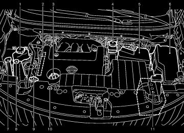
COCKPIT
Black plate (78,1)
11. Fuse box cover 12. Fuel-filler door opener handle 13. Hood release handle 14. Headlight aiming control* 15. Power door main switch* 16. Steering-wheel-mounted controls (left side)
— Audio control steering switch — Hands-Free Phone System switch*
17. Horn 18. Steering-wheel-mounted controls (right side)
— Cruise control system if so equipped
*:
1. Vehicle Dynamic Control (VDC) OFF switch 2. Blind Spot Warning (BSW) switch*
— Blind Spot Warning (BSW)*
3. Sliding door switch* (driver’s side) 4. Sliding door switch* (passenger’s side) 5. 6. Power lift gate switch* 2-2 Instruments and controls
Instrument brightness control switch
SSI0825
7. Headlight, fog light and turn signal switch
— Headlight — Turn signal — Fog light* Trip computer switch TRIP/RESET switch for twin trip odometer
8. 9. 10. Wiper and washer switch
Model "E52-D" EDITED: 2010/ 10/ 25
Black plate (79,1)
INSTRUMENT PANEL
11. Parking brake 12. Tilting telescopic steering wheel lever or switch 13. Front passenger air bag status light 14. Heated seat switch* 15. Cup holders 16. Power outlet 17. 18. Power outlet main switch* 19. Audio system 20. Glove box *: **: Refer to the separate Navigation System Owner’s
Instrument lower box or CD/DVD slot
if so equipped
1. Side ventilator 2. Meters and gauges 3. Push-button ignition switch 4. Hazard warning flasher switch 5. Selector lever 6. Center display
— Center color display*
SSI0824
— Navigation system**
7. Center multi-function control panel*
— Navigation system** — Vehicle information and setting buttons*
8. Rear window and outside mirror* defroster switch 9. Center ventilator 10. Heater/air conditioner control or audio system
Manual (if so equipped).
Instruments and controls 2-3
Model "E52-D" EDITED: 2010/ 10/ 25
METERS AND GAUGES
Instrument brightness control switch Tachometer
1. 2. 3. Speedometer 4. 5. Warning/indicator lights 6.
Trip computer switch
Fuel gauge
Black plate (80,1)
after the ignition switch is pushed to the OFF position. This is not a malfunction.
METER/RING ILLUMINATION AND NEEDLE SWEEP The ring illumination surrounding meters and gauges illuminates when the driver’s door is closed after getting into the vehicle with the Intelligent Key carried in.
When the engine is started, the indicator needles will sweep in the speedometer and tachometer and the ring illumination will be brightened gradually. This function can be turned off. (See “TRIP COMPUTER” later in this section.)
SIC4630
7. Dot matrix liquid crystal display
— Trip computer
8. Engine coolant temperature gauge 9. Odometer/twin trip odometer/Continuously Vari-
able Transmission (CVT) position indicator 10. TRIP/RESET switch for twin trip odometer The needle indicators may move slightly
2-4 Instruments and controls
Model "E52-D" EDITED: 2010/ 10/ 25
Black plate (81,1)
Resetting the trip odometer: Pushing the TRIP RESET switch *3
for more than 1 second resets the trip odometer to zero.Instruments and controls 2-5
Model "E52-D" EDITED: 2010/ 10/ 25
SIC3571
SIC4632
Speedometer
SPEEDOMETER AND ODOMETER Speedometer The speedometer indicates vehicle speed in miles per hour (MPH) and kilometers per hour (km/h).
Odometer/twin trip odometer
Odometer/twin trip odometer and twin trip odometer *2
The odometer *1
are displayed when the ignition switch is in the ON position.The odometer records the total distance the vehicle has been driven.
The twin trip odometer records the distance of individual trips.
Changing the display: Pushing the TRIP RESET switch *3 on the right side of the combination meter panel changes the display as follows: TRIP A ? TRIP B ? TRIP A
Black plate (82,1)
CAUTION
If the gauge indicates engine coolant temperature near the hot (H) end of the normal range, reduce vehicle speed to decrease temperature. If gauge is over the normal range, stop the vehicle as soon as safely possible and let the engine idle. If the engine is overheated, continued operation of the vehicle may seriously damage the engine. See “IF YOUR VEHICLE OVERHEATS” in the “6. In case of emergency” section for immediate action required.
Model "E52-D" EDITED: 2010/ 10/ 25
SIC4633
SIC4634
TACHOMETER The tachometer indicates engine speed in revolutions per minute (RPM). Do not rev the engine into the red zone *1 .
ENGINE COOLANT TEMPERATURE GAUGE The gauge indicates the engine coolant tem- perature.
CAUTION
When engine speed approaches the red zone, shift to a higher gear or reduce engine speed. Operating the engine in the red zone may cause serious engine damage.
The engine coolant temperature is within the normal range when the gauge needle points within the zone *1
The engine coolant temperature varies with the outside air temperature and driving conditions.shown in the illustration.
2-6 Instruments and controls
convenient, preferably before the gauge reaches “0”. There will be a small reserve of fuel in the tank when the fuel gauge needle reaches “0”.
The located on the driver’s side of the vehicle.
indicates that the fuel-filler door is
CAUTION
malfunction indicator
If the vehicle runs out of fuel, the light (MIL) may come on. Refuel as soon as possible. After a few driving trips, the light should turn off. If the light remains on after a few driving trips, have the vehicle inspected by a NISSAN dealer.
. For additional
information, see “Malfunction Indicator Light (MIL)” later in this section.
SIC4714
FUEL GAUGE The gauge indicates the approximate fuel level in the tank.
The gauge may move slightly during braking, turning, acceleration, or going up or down hills.
The gauge needle returns to “0” (empty) after the ignition switch is pushed to the OFF position.
Refill the fuel tank before the gauge registers “0” (empty).
The low fuel warning appears on the dot matrix liquid crystal display when the fuel level in the tank is getting low. Refuel as soon as it is
Black plate (83,1)
COMPASS (if so equipped)
SIC3181
When the ignition switch is pushed to the ON position, the compass display *B will indicate the direction of the vehicle’s heading.
Instruments and controls 2-7
Model "E52-D" EDITED: 2010/ 10/ 25
Black plate (84,1)
If the display reads “C”, calibrate the compass by driving the vehicle in 3 complete circles at less than 5 MPH (8 km/h). You can also calibrate the compass by driving your vehicle on your everyday route. The compass will be calibrated once it has tracked 3 complete circles.
To turn on and off the compass manually, push switch *A while the ignition switch is in the the ON position.
2-8 Instruments and controls
Zone map
SIC0611B
Model "E52-D" EDITED: 2010/ 10/ 25
Black plate (85,1)
ZONE VARIATION CHANGE PROCE- DURE The difference between magnetic north and geographical north is known as variance. In some areas, this difference can sometimes be great enough to cause false compass readings. Follow these instructions to set the variance for your particular location if this happens:
1. Push the
switch for more than 3
seconds. The current zone number will appear in the display.2. Find your current
location and variance
number on the zone map.
NOTE: Use zone number 5 for Hawaii.
pass point when the vehicle moves to an area where the geomagnetism is stabilized.)
CAUTION
. Do not install a ski rack, antenna, etc., which are attached to the vehicle by means of a magnet. They affect the operation of the compass. . When cleaning the mirror, use a paper towel or similar material dampened with glass cleaner. Do not spray glass cleaner directly on the mirror as it may cause the liquid cleaner to enter the mirror housing.
3. Push the
switch repeatedly until the new zone number appears in the display, then release the switch. After you release the switch, the display will show a compass direction within a few seconds.
If the compass deviates from the correct indication soon after repeated adjust- ment, have the compass checked at a NISSAN dealer.
The compass may not correct compass point while driving up or down a steep hill.
indicate the in tunnels or
(The compass returns to the correct com-
Instruments and controls 2-9
Model "E52-D" EDITED: 2010/ 10/ 25
Black plate (86,1)
WARNING/INDICATOR LIGHTS AND AUDIBLE REMINDERS
Anti-lock Braking System (ABS) warning light
Brake warning light
Blind Spot Warning (BSW) system warning light (orange)*
Charge warning light
Engine oil pressure warning light
Hydraulic pump electric power steering warning light
Intelligent Key system warning light
Front passenger air bag status light
Low tire pressure warning light
High beam indicator light
Master warning light
Low beam indicator light
Seat belt warning light and chime
Malfunction Indicator Light (MIL)
Supplemental air bag warning light
Overdrive off indicator light
Vehicle Dynamic Control (VDC) warning light
Continuously Variable Transmission (CVT) position indicator light
Cruise indicator light
Security indicator light
Turn signal/hazard indicator lights
Vehicle Dynamic Control (VDC) off indicator light
*: if so equipped
CHECKING BULBS With all doors closed, apply the parking brake and push the ignition switch to the ON position without starting the engine. The following lights will come on (if so equipped):
or
The following lights come on briefly and then go off (if so equipped):
2-10 Instruments and controls
or
CRYSTAL DISPLAY” later in this section.)
If any light does not come on, it may indicate a burned-out bulb or an open circuit in the electrical system. Have the system checked by a NISSAN dealer.
Some indicators and warnings are also dis- played on the dot matrix crystal display on the speedometer. (See “DOT MATRIX LIQUID
WARNING LIGHTS
or
Anti-lock Braking System (ABS) warning light
When the ignition switch is in the ON position, the Anti-lock Braking System (ABS) warning light illuminates and then turns off. This indicates
Model "E52-D" EDITED: 2010/ 10/ 25
the ABS is operational.
tion.)
If the ABS warning light illuminates while the engine is running, or while driving, it may indicate the ABS is not functioning properly. Have the system checked by a NISSAN dealer.
If an ABS malfunction occurs, the anti-lock function is turned off. The brake system then operates normally, but without anti-lock assis- tance. (See “BRAKE SYSTEM” in the “5. Starting and driving” section.)
or
Brake warning light
This light functions for both the parking brake and the foot brake systems.
Parking brake indicator:
When the ignition switch is in the ON position, the light comes on when the parking brake is applied.
Low brake fluid warning light:
When the ignition switch is in the ON position, the light warns of a low brake fluid level. If the light comes on while the engine is running with the parking brake not applied, stop the vehicle and perform the following:
1. Check the brake fluid level. Add brake fluid as necessary. (See “BRAKE FLUID” in the “8. Maintenance and do-it-yourself” sec-
2.
is correct, have the If the brake fluid level warning system checked by a NISSAN dealer.
Anti-lock Braking System (ABS) warning indicator:
When the parking brake is released and the brake fluid level is sufficient, if both the brake warning light and the Anti-lock Braking System (ABS) warning light illuminate, it may indicate the ABS is not functioning properly. Have the brake system checked, and if necessary re- paired, by a NISSAN dealer promptly. (See “Anti-lock Braking System (ABS) warning light” earlier in this section.)
WARNING
. Your brake system may not be working properly if the warning light is on. Driving could be dangerous. If you judge it to be safe, drive care- fully to the nearest service station for repairs. Otherwise, have your vehicle towed because driving it could be dangerous.
. Pressing the brake pedal with the engine stopped and/or low brake fluid level may increase your stop-
Black plate (87,1)
ping distance and braking will re- quire greater pedal effort as well as pedal travel.
If the brake fluid level is below the minimum or MIN mark on the brake fluid reservoir, do not drive until the brake system has been checked at a NISSAN dealer.
Blind Spot Warning (BSW) sys- tem warning light (orange; if so equipped)
If the light comes on in orange and remains on, it may indicate that the BSW system is not functioning properly. Although the vehicle is still driveable, have the system checked by a NISSAN dealer. See “BLIND SPOT WARNING (BSW) SYSTEM” in the “5. Starting and driving” section.
Charge warning light
If the light comes on while the engine is running, it may indicate the charging system is not functioning properly. Turn the engine off and check the alternator belt. If the belt is loose, broken, missing or if the light remains on, see a NISSAN dealer immediately.
Instruments and controls 2-11
Model "E52-D" EDITED: 2010/ 10/ 25
Black plate (88,1)
CAUTION
Do not continue driving if the alternator belt is loose, broken or missing.
Engine oil pressure warning light
This light warns of low engine oil pressure. If the light flickers or comes on during normal driving, pull off the road in a safe area, stop the engine immediately and call a NISSAN dealer or other authorized repair shop.
The engine oil pressure warning light is not designed to indicate a low oil level. Use the dipstick to check the oil level. (See “ENGINE OIL” in the “8. Maintenance and do-it- yourself” section.)
CAUTION
Running the engine with the engine oil pressure warning light on could cause serious damage to the engine almost immediately. Such damage is not cov- ered by warranty. Turn off the engine as soon as it is safe to do so.
2-12 Instruments and controls
Hydraulic pump electric power steering warning light
When the ignition switch is in the ON position, the hydraulic pump electric power steering illuminates. After starting the warning light engine, the hydraulic pump electric power steering warning light turns off. This indicates that the electric power steering system is operational.
If the hydraulic pump electric power steering warning light illuminates while the engine is running, it may indicate the hydraulic pump electric power steering system is not functioning properly and may need servicing. Have the hydraulic pump electric power steering system checked by a NISSAN dealer. (See “HYDRAU- LIC PUMP ELECTRIC POWER STEERING SYSTEM” in the “5. Starting and driving” section.)
Intelligent Key system warning light
After the ignition switch is pushed to the ON position, this light comes on for about 2 seconds and then turns off.
This light warns of a malfunction with the Intelligent Key system.
If
the light comes on while the engine is
it may be impossible to start
stopped, the engine. If the light comes on while the engine is running, you can drive the vehicle. However in these cases, contact a NISSAN dealer for repair as soon as possible.
Low tire pressure warning light
Your vehicle is equipped with a Tire Pressure Monitoring System (TPMS) that monitors the tire pressure of all tires except the spare.
The low tire pressure warning light warns of low tire pressure or indicates that the TPMS is not functioning properly.
After the ignition switch is pushed ON, this light illuminates for about 1 second and turns off.
Low tire pressure warning:
the vehicle is being driven with low tire If pressure, illuminate. A CHECK TIRE PRESSURE warning also appears on the dot matrix liquid crystal display.
the warning light will
When the low tire pressure warning light illuminates, you should stop and adjust the tire pressure to the recommended COLD tire pressure shown on the Tire and Loading Information label. The low tire pressure warning light does not automatically turn off when the tire pressure is adjusted. After the tire is inflated to the recommended pressure, the vehicle must be
Model "E52-D" EDITED: 2010/ 10/ 25
driven at speeds above 16 MPH (25 km/h) to activate the TPMS and turn off the low tire pressure warning light. Use a tire pressure gauge to check the tire pressure.
The CHECK TIRE PRESSURE warning is active as long as the low tire pressure warning light remains illuminated.
For additional information, see “TIRE PRES- SURE MONITORING SYSTEM (TPMS)” in the “5. Starting and driving” section and “TIRE PRESSURE MONITORING SYSTEM (TPMS)” in the “6. In case of emergency” section.
TPMS malfunction:
If the TPMS is not functioning properly, the low tire pressure warning light will flash for approxi- mately 1 minute when the ignition switch is pushed ON. The light will remain on after the 1
minute. Have the system checked by a NISSAN dealer. The CHECK TIRE PRESSURE warning does not appear if the low tire pressure warning light illuminates to indicate a TPMS malfunction.For additional information, see “TIRE PRES- SURE MONITORING SYSTEM (TPMS)” in the “5. Starting and driving” section. For the CHECK TIRE PRESSURE warning, see “DOT MATRIX LIQUID CRYSTAL DISPLAY” later in this section.
WARNING
If the light does not illuminate with the ignition switch pushed ON, have the vehicle checked by a NISSAN dealer as soon as possible.
If the light illuminates while driving, avoid sudden steering maneuvers or abrupt braking, reduce vehicle speed, pull off the road to a safe location and stop the vehicle as soon as possible. Driving with un- der-inflated tires may permanently damage the tires and increase the likelihood of tire failure. Serious vehicle damage could occur and may lead to an accident and could result in serious personal injury. Check the tire pressure for all four tires. Adjust the tire pressure to the recommended COLD tire pressure shown on the Tire and Loading Information label to turn the low tire pressure warning light OFF. If the light still illuminates while driv- ing after adjusting the tire pressure, a tire may be flat. If you have a flat tire, replace it with a spare tire as soon as possible.
Black plate (89,1)
. When a spare tire is mounted or a wheel is replaced, the TPMS will not function and the low tire pressure warning light will flash for approxi- mately 1 minute. The light will remain on after 1 minute. Contact your NISSAN dealer as soon as possible for tire replacement and/ or system resetting.
. Replacing tires with those not ori- ginally specified by NISSAN could affect the proper operation of the TPMS.
CAUTION
The TPMS is not a substitute for the regular tire pressure check. Be sure to check the tire pressure regularly.
If the vehicle is being driven at speeds of less than 16 MPH (25
km/h), the TPMS may not operate correctly.. Be sure to correctly install
the specified size of tires to the four wheels.
Instruments and controls 2-13
Model "E52-D" EDITED: 2010/ 10/ 25
Black plate (90,1)
fastened when the front passenger’s seat is occupied. For approximately 5 seconds after the ignition switch is in the ON position, the system does not activate the warning light for the front passenger.
See “SEAT BELTS” in the “1. Safety — Seats, seat belts and supplemental restraint system” section for precautions on seat belt usage.
Supplemental air bag warning light
After pushing the ignition switch to the ON position, the supplemental air bag warning light will illuminate. The supplemental air bag warning light will turn off after about 7 seconds if the supplemental front air bag and supplemental side air bag, curtain side-impact air bag systems and/or pretensioner seat belt are operational.
If any of the following conditions occur, the front air bag, side air bag, curtain air bag and pretensioner systems needs servicing and your vehicle must be taken to your nearest NISSAN dealer.
The supplemental air bag warning light remains on after approximately 7 seconds.
The supplemental air bag warning light flashes intermittently.
The supplemental air bag warning light does not come on at all.
Unless checked and repaired, the Supplemental Restraint Systems (air bag systems) and/or the pretensioners may not function properly.
For additional information, see “SUPPLEMEN- TAL RESTRAINT SYSTEM” in the “1. Safety — Seats, seat belts and supplemental restraint system” section.
WARNING
If the supplemental air bag warning light is on, it could mean that the front air bag, side air bag, curtain air bag and/or pretensioner systems will not operate in an accident. To help avoid injury to yourself or others, have your vehicle checked by a NISSAN dealer as soon as possible.
Vehicle Dynamic Control (VDC) warning light
The light will blink when the VDC system or the traction control system is operating, thus alerting the driver that the vehicle is nearing its traction limits. The road surface may be slippery.
When the vehicle dynamic control warning light illuminates when the vehicle dynamic control system is turned on, this light alerts the driver to
Model "E52-D" EDITED: 2010/ 10/ 25
Master warning light
When the ignition switch is in the ON position, the master warning light illuminates if any of the following are displayed on the dot matrix liquid crystal display: . No key warning
Low fuel warning
Low washer fluid warning
. Parking brake release warning . Door/lift gate open warning . Check tire pressure warning
Loose fuel cap warning
See “DOT MATRIX LIQUID CRYSTAL DIS- PLAY” later in this section.
Seat belt warning light and chime
The light and chime remind you to fasten seat belts. The light illuminates whenever the ignition switch is pushed to the ON position, and will remain illuminated until the driver’s seat belt is fastened. At the same time, the chime will sound for approximately 6 seconds unless the driver’s seat belt is securely fastened.
The seat belt warning light passenger will 2-14 Instruments and controls
the front illuminate if the seat belt is not
for
Black plate (91,1)
that
the fact the vehicle dynamic control system’s fail-safe mode is operating, for example the vehicle dynamic control system may not be functioning properly. Have the system checked by a NISSAN dealer. If a malfunction occurs in the system, the vehicle dynamic control system function will be canceled but the vehicle is still driveable. For additional information, see “VE- HICLE DYNAMIC CONTROL (VDC) SYSTEM” in the “5. Starting and driving” section of this manual.
INDICATOR LIGHTS
Continuously Variable Transmis- sion (CVT) position indicator light
When the ignition switch is pushed to the ON position, the indicator shows the automatic selector shift position. (See “CONTINUOUSLY VARIABLE TRANSMISSION (CVT)” in the “5. Starting and driving” section.)
Cruise indicator light
Cruise main switch indicator:
This light illuminates when the cruise control main switch is pushed. The light turns off when the main switch is pushed again. When the cruise main switch indicator light illuminates, the cruise control system is operational. (See
“CRUISE CONTROL” in the “5. Starting and driving” section.)
Low beam indicator light
Cruise malfunction:
the cruise indicator
light blinks while the If engine is running, it may indicate the cruise control system is not functioning properly. Have the system checked by a NISSAN dealer. (See “CRUISE CONTROL” in the “5. Starting and driving” section.)
Front passenger air bag status light
The front passenger air bag status light ( will be lit and the passenger front air bag will be OFF depending on how the front passenger seat is being used.
For front passenger air bag status light opera- tion, see “NISSAN ADVANCED AIR BAG SYSTEM (front seats)” in the “1. Safety — Seats, seat belts and supplemental restraint system” section of this manual.
High beam indicator light
This light comes on when the headlight high beam is on and goes out when the low beam is selected.
The light comes on when the front park, side marker, tail and license plate lights are on.
Malfunction Indicator Light (MIL)
the malfunction indicator
If light comes on steady or blinks while the engine is running, it may indicate a potential emission control.
The malfunction indicator light may also come on steady if the fuel-filler cap is loose or missing, or if the vehicle runs out of fuel. Check to make sure the fuel-filler cap is installed and closed tightly, and that the vehicle has at least 3 US gallons (11.4 liters) of fuel in the fuel tank.
light should After a few driving trips, the turn off if no other potential emission control system malfunction exists.
If this indicator light remains on for 20 seconds and then blinks for 10 seconds when the engine is not running, it indicates that the vehicle is not ready for an emission control system inspection/ maintenance test. (See “READINESS FOR INSPECTION/MAINTENANCE (I/M) TEST” in the “9. Technical and consumer information” section.)
Instruments and controls 2-15
Model "E52-D" EDITED: 2010/ 10/ 25
Operation:
blinking and remain on.
The malfunction indicator light will come on in one of two ways: . Malfunction indicator light on steady — An emission control system has been detected. Check the fuel-filler cap if the LOOSE FUEL CAP warning appears on the dot matrix liquid crystal display. If the fuel-filler cap is loose or missing, tighten or install the cap and continue to drive the vehicle. The light should turn off after a few driving trips. light does not turn off after a few If the driving trips, have the vehicle inspected by a NISSAN dealer. You do not need to have your vehicle towed to the dealer.
. Malfunction indicator light blinking — An engine misfire has been detected which may damage the emission control system.
To reduce or avoid emission control system damage:
a) Do not drive at speeds above 45 MPH
(72 km/h).
b) Avoid hard acceleration or deceleration.
c) Avoid steep uphill grades.
d) If possible, reduce the amount of cargo
being hauled or towed.
The malfunction indicator
light may stop
2-16 Instruments and controls
Have the vehicle inspected by a NISSAN dealer. You do not need to have your vehicle towed to the dealer.
CAUTION
Continued vehicle operation without having the emission control system and repaired as necessary could lead to poor driveability, reduced fuel econ- omy, and possible damage to the emis- sion control system.
Overdrive off indicator light
The overdrive off indicator light illuminates when the overdrive off mode is selected.
For additional information, see ““CONTINU- OUSLY VARIABLE TRANSMISSION (CVT)” in the “5. Starting and driving” section of this manual.
Security indicator light
The light blinks when the ignition switch is in the ACC, OFF or LOCK position. This function indicates the security system equipped on the vehicle is operational.
Black plate (92,1)
If the security system is malfunctioning, this light will remain on while the ignition switch is in the ON position. For additional information, see “SECURITY SYSTEMS” later in this section.
Turn signal/hazard indicator lights
The light flashes when the turn signal switch lever or hazard switch is turned on.
Vehicle Dynamic Control (VDC) off indicator light
The light comes on when the vehicle dynamic control off switch is pushed to OFF. This indicates that the vehicle dynamic control system and traction control system are not operating.
AUDIBLE REMINDERS Key reminder chime A chime will sound if the driver side door is opened while the ignition switch is pushed to the ACC position. Make sure the ignition switch is pushed to the OFF position, and take the Intelligent Key with you when leaving the vehicle.
Light reminder chime A chime will sound when the driver side door is or opened with the light switch in the position and the ignition switch in the ACC
Model "E52-D" EDITED: 2010/ 10/ 25
or OFF position.
Turn the light switch off when you leave the vehicle.
The chime will also sound for 2 seconds when the ignition switch is turned to the OFF position with the fog lights on while the headlight switch is in the AUTO position.
Parking brake reminder chime The chime will sound if the vehicle is driven at more than 4 MPH (7 km/h) with the parking brake applied. Stop the vehicle and release the parking brake.
Brake pad wear warning The disc brake pads have audible wear warn- ings. When a brake pad requires replacement, it will make a high pitched scraping sound when the vehicle is in motion. This scraping sound will first occur only when the brake pedal is depressed. After more wear of the brake pad, the sound will always be heard even if the brake pedal is not depressed. Have the brakes checked as soon as possible if the warning sound is heard.
Black plate (93,1)
DOT MATRIX LIQUID CRYSTAL DISPLAY
SIC4715
The dot matrix liquid crystal display *1
is located in the speedometer, and it displays, the key operation information and other warn- ings and information.For the detail about the Intelligent Key System, see “INTELLIGENT KEY SYSTEM” in the “3. Pre-driving checks and adjustments” section.
Instruments and controls 2-17
Model "E52-D" EDITED: 2010/ 10/ 25
Black plate (94,1)
INDICATORS FOR OPERATION 1. Engine start operation indicator This indicator appears when the selector lever is in the P (Park) position.
This indicator means that the engine will start by
2-18 Instruments and controls
pushing the ignition switch with the brake pedal depressed.
You can start the engine directly in any position.
2. NO KEY warning This warning appears in either of the following conditions.
SIC4716
No key inside the vehicle:
The warning appears when the door is closed
Model "E52-D" EDITED: 2010/ 10/ 25
with the Intelligent Key left outside the vehicle and the ignition switch in the ACC or ON position. Make sure that the Intelligent Key is inside the vehicle.
Unregistered key:
The warning appears when the ignition switch is pushed from the LOCK position and the key cannot be recognized by the system. You cannot start the engine with an unregistered key. Use the registered key.
See “INTELLIGENT KEY SYSTEM” in the “3. Pre-driving checks and adjustments” section for more details.
3. SHIFT “P” warning This warning appears when the ignition switch is pushed to stop the engine with the selector lever in any position except the P (Park) position.
If this warning appears, move the selector lever to the P (Park) position or push the ignition switch to the ON position.
An inside warning chime will also sound. (See “INTELLIGENT KEY SYSTEM” in the “3. Pre- driving checks and adjustments” section.)
4. “PUSH” warning This warning appears when the selector lever is moved to the P (Park) position with the ignition switch in the ACC position after the SHIFT “P”
warning appears.
To push the ignition switch to the OFF position, perform the following procedure:
SHIFT “P” warning ? (Move the selector lever to “P”) ? PUSH warning ? (Push the ignition switch ? ignition switch position is turned to ON) ? PUSH warning ? (Push the ignition switch ? ignition switch position is turned to OFF)
5. Key battery discharge indicator This indicator appears when the key battery is running out of power.
If this indicator appears, replace the battery with a new one. (See “INTELLIGENT KEY BATTERY REPLACEMENT” in the “8. Maintenance and do-it-yourself” section.)
6. Engine start operation for Intelligent Key system indicator This indicator appears when the Intelligent Key battery is running out of power and when the Intelligent Key System and vehicle are not communicating normally.
this indicator appears,
If touch the ignition switch with the Intelligent Key while depressing the brake pedal. (See “INTELLIGENT KEY BATTERY DISCHARGE” in the “5. Starting and driving” section.)
Black plate (95,1)
7. Parking brake release warning This warning appears when the vehicle speed is above 4 MPH (7 km/h) and the parking brake is applied. Stop the vehicle and release the parking brake.
8. Low fuel warning This warning appears when the fuel level in the tank is getting low. Refuel as soon as it is convenient, preferably before the fuel gauge reaches the empty (0) position.
There is a small reserve of fuel remaining in the tank when the fuel gauge reaches the empty (0) position.
9. Low washer fluid warning This warning appears when the washer tank fluid is at a low level. Add washer fluid as necessary. (See “WINDOW WASHER FLUID” in the “8. Maintenance and do-it-yourself” section.)
10. Door/lift gate open warning (ignition switch is in the ON position) This warning appears if any of the doors and/or the lift gate are open or not closed securely. The vehicle icon indicates which door is open on the display.
11. Loose fuel cap warning This warning appears when the fuel-filler cap is not the vehicle has
tightened correctly after
Instruments and controls 2-19
Model "E52-D" EDITED: 2010/ 10/ 25
been refueled. (See “FUEL-FILLER CAP” in the “3. Pre-driving checks and adjustments” sec- tion.)
12. Check tire pressure warning This warning appears when the low tire pressure warning light in the meter illuminates and low tire pressure is detected. If this warning appears, stop the vehicle and adjust the tire pressure to the recommended COLD tire pressure shown on the Tire and Loading Information label. (See “Low tire pressure warning light” earlier in this section and “TIRE PRESSURE MONITORING SYSTEM (TPMS)” in the “5. Starting and driving” section.)
13. “TIMER” indicator This indicator appears when the set “timer” indicator activates. You can set the time for up to 6 hours. (See “TRIP COMPUTER” later in this section.)
14. Low outside temperature warning This warning appears if the outside temperature is below 378F (38C). The warning can be set not to be displayed. (See “TRIP COMPUTER” later in this section.)
2-20 Instruments and controls
SIC4237
INDICATORS FOR MAINTENANCE 1. Engine oil replacement indicator This indicator appears when the set time comes for changing the engine oil. You can set or reset the distance for changing the engine oil. (See “TRIP COMPUTER” later in this section.)
Black plate (96,1)
2. Oil filter replacement indicator This indicator appears when the set time comes for replacing the oil filter. You can set or reset the distance for replacing the oil filter. (See “TRIP COMPUTER” later in this section.)
3. Tire replacement indicator This indicator appears when the set time comes for replacing tires. You can set or reset the distance for replacing tires. (See “TRIP COM- PUTER” later in this section.)
4. “OTHER” indicator This indicator appears when the set time comes for replacing items other than the engine oil, oil filter and tires. You can set or reset the distance for replacing the items. (See “TRIP COMPU- TER” later in this section.)
More maintenance reminders are also available on the center display. (models with center multi- function control panel) (See “HOW TO USE INFO BUTTON” in the “4. Monitor, heater, air conditioner, audio, phone and voice recognition systems” section.)
Model "E52-D" EDITED: 2010/ 10/ 25
Current and average fuel consumption ? Average fuel consumption and speed ? Elapsed time and trip odometer ? Distance to empty (dte) ? Outside air temperature (ICY) ? Setting ? Warning check
SIC3580
TRIP COMPUTER Switches for the trip computer are located on the right side of the combination meter panel. To operate the trip computer, push the side of the switches as shown above. *A *B When the ignition switch is pushed to the ON position, modes of the trip computer can be selected by pushing the
switch *A .
switch
switch
switch *A Each time the display will change as follows:
is pushed, the
Black plate (97,1)
SIC4700
Current and average fuel consumption (MPG, l (liter)/100 km or km/l) The current and average fuel consumption mode shows the current and average fuel consump- tion.
Instruments and controls 2-21
Model "E52-D" EDITED: 2010/ 10/ 25
Black plate (98,1)
vehicle speed since the last reset. Resetting is switch *B for longer done by pushing the than 1 second. (The average fuel consumption is also reset at the same time.)
The display is updated every 30 seconds. The first 30 seconds after a reset, the display shows “——”.
SIC4701
Elapsed time and trip odometer (miles or km)
Elapsed time:
The elapsed time mode shows the time since the last reset. The displayed time can be reset switch *B for longer than by pushing the 1 second. (The trip odometer is also reset at the same time.)
Trip odometer:
The trip odometer mode shows the total distance the vehicle has been driven since the last reset. Resetting is done by pushing the switch *B than 1 second. elapsed time is also reset at the same time.)
longer
(The
for
Model "E52-D" EDITED: 2010/ 10/ 25
SIC3674
Average fuel consumption (MPG, l/100
km or km/l) and speed (MPH or km/h)Fuel consumption:
The average fuel consumption mode shows the average fuel consumption since the last reset. switch *B Resetting is done by pushing the for longer than 1 second. (The average speed is also reset at the same time.)
The display is updated every 30 seconds. At about the first 1/3 mile (500 m) after a reset, the display shows “——”.
Speed:
The average speed mode shows the average
2-22 Instruments and controls
Black plate (99,1)
pushed to the OFF position may continue to be displayed.
. When driving uphill or rounding curves, the fuel in the tank shifts, which may momenta- rily change the display.
SIC4703
Outside air temperature (ICY — 8F or 8C) The outside air temperature is displayed in 8F or 8C in the range of −22 to 1408F (−30 to 608C).The outside air temperature mode includes a low temperature warning feature. If the outside air temperature is below 378F (38C), the warning is displayed on the screen.
The outside temperature sensor is located in front of the radiator. The sensor may be affected by road or engine heat, wind directions and other driving conditions. The display may differ from the actual outside temperature or the temperature displayed on various signs or bill- boards.
Instruments and controls 2-23
Model "E52-D" EDITED: 2010/ 10/ 25
SIC4702
Distance to empty (dte — miles or km) The distance to empty (dte) mode provides you with an estimation of the distance that can be driven before refueling. The dte is constantly being calculated, based on the amount of fuel in the fuel tank and the actual fuel consumption.
The display is updated every 30 seconds.
The dte mode includes a low range warning feature. level is low, the warning is displayed on the screen.
If the fuel
level drops even lower, the dte
When the fuel display will change to “——”.
If the amount of fuel added is small, the display just before the ignition switch is
Black plate (100,1)
ALERT:
. OTHER
Alert menu can be set to notify the following items.
TIMER
Select this submenu to specify when the “TIMER” indicator activates.
Select this submenu and set or reset the distance for replacing items other than the engine oil, oil filter and tires.
To return to the top page of the setting mode, select “BACK”.
ICY
Select outside temperature warning.
this submenu to display the low
To return to the top page of the setting mode, select “BACK”.
MAINTENANCE:
The maintenance intervals of the following items can be set or reset for the reminders. . OIL
Select distance for changing the engine oil.
this submenu to set or reset
the
FILTER
Select distance for replacing the oil filter.
this submenu to set or reset
the
TIRE
OPTIONS:
The 3 option menus can be set preference.
LANGUAGE
to your
Select French or Spanish for display.
this submenu to choose English,
. UNIT
Select this submenu to choose the unit from MPG or l/100 km.
. EFFECTS
Select this menu to set scribed below to on or off.
the effects de-
— The indicator needles sweep in the meters and the ring illumination will be brightened gradually when the engine is started.
Select distance for replacing tires.
this submenu to set or reset
the
To return to the top page of the setting mode, select “BACK”.
Model "E52-D" EDITED: 2010/ 10/ 25
SIC3678
Setting Setting cannot be made while driving. A message “Setting can only be operated when stopped” is also displayed on the dot matrix crystal display. switch *A and
switch *B are The used in the setting mode to select and decide a menu.
SKIP:
Push the warning check mode.
switch *A
to move to the
Push the
switch *B to select other menus.
2-24 Instruments and controls
Black plate (101,1)
SECURITY SYSTEMS
to move to the
SKIP:
Push the warning check mode.
switch *A
Push the
DETAIL:
switch *B to select other menus.
This item is available only when a warning is displayed.
Select this menu to see the details of warnings.
SIC3993
Warning check To see if there are any of the following warnings and corresponding details, select this menu. . No key warning
Low fuel warning
Low washer fluid warning
. Parking brake release warning . Door/lift gate open warning . Check tire pressure warning
Loose fuel cap warning
SIC4717
Your vehicle has two types of security systems, as follows: . Vehicle security system . NISSAN Vehicle Immobilizer System
The security condition will be shown by the security indicator light.
VEHICLE SECURITY SYSTEM The vehicle security system provides visual and audio alarm signals if someone opens the doors or lift gate when the system is armed. It is not, however, a motion detection type system that activates when a vehicle is moved or when a vibration occurs.
Instruments and controls 2-25
Model "E52-D" EDITED: 2010/ 10/ 25
The system helps deter vehicle theft but cannot prevent it, nor can it prevent the theft of interior or exterior vehicle components in all situations. Always secure your vehicle even if parking for a brief period. Never leave your Intelligent Key(s) in the vehicle, and always lock it when un- attended. Be aware of your surroundings, and park in secure, well-lit areas whenever possible.
Many devices offering additional protection, such as component locks, identification markers, and tracking systems, are available at auto supply stores and specialty shops. Your NISSAN dealer may also offer such equipment. Check with your insurance company to see if you may be eligible for discounts for various theft protection features.
2-26 Instruments and controls
SIC2045
How to arm the vehicle security system 1. Close all windows.
The system can be armed even if the windows are open.
2. Push the ignition switch to the OFF position.
3. Remove the Intelligent Key from the vehicle.
4. Close all doors and lift gate. Lock all doors. The doors can be locked with the Intelligent Key, door handle request switch, power door lock switch or mechanical key.
5. Confirm that
the security indicator
light comes on. The security indicator light stays on for about 30 seconds. The vehicle
Black plate (102,1)
security system is now pre-armed. After about 30 seconds the vehicle security system automatically shifts into the armed phase. The security light begins to flash once every approximately 3 seconds. If, during this 30-second pre-arm time period, the door is unlocked, or the ignition switch is pushed to ACC or ON, the system will not arm.
Even when the driver and/or passengers are in the vehicle, the system will activate with all doors and lift gate locked with the ignition switch in the LOCK position. When pushing the ignition switch to the ACC or ON position, the system will be released.
Vehicle security system activation The vehicle security system will give the follow- ing alarm:
The headlights blink and the horn sounds intermittently.
The alarm automatically turns off after approximately 1 minute. However, the alarm reactivates if the vehicle is tampered with again.
The alarm is activated by: . Unlocking the door or opening the lift gate without using the button on the Intelligent Key, the door handle request switch or the
Model "E52-D" EDITED: 2010/ 10/ 25
mechanical key. (Even if the door is opened by releasing the door inside lock knob, the alarm will activate.)
How to stop an activated alarm The alarm will stop by unlocking a door by pushing the unlock button on the Intelligent Key, the door handle request switch or using the mechanical key. The alarm will not stop if the ignition switch is pushed to the ACC or ON position.
If the system does not operate as de- scribed above, have it checked by a NISSAN dealer.
NISSAN VEHICLE IMMOBILIZER SYS- TEM The NISSAN Vehicle Immobilizer System will not allow the engine to start without the use of the registered Intelligent Key. Never leave these keys in the vehicle.
For USA:
This device complies with Part 15 of the FCC Rules. Operation is subject to the following two conditions:
(1) This device may not cause harmful interference, and (2) this device must accept any interference received, including interference that may cause undesired
Black plate (103,1)
operation.
Note: Changes or modifications not ex- pressly approved by the party responsible for compliance could void the user’s authority to operate the equipment.
For Canada:
This device complies with RSS-210 of Industry Canada. Operation is subject to the following two conditions:
(1) this device may not cause interference, and (2) this device must accept any inter- ference, including interference that may cause undesired operation of the device.
SIC2045
Security indicator light The security indicator light is located on the meter panel. the NISSAN Vehicle Immobilizer System.
indicates the status of
It
The light blinks after the ignition switch is in the LOCK, ACC or OFF position. This function indicates the security systems equipped on the vehicle are operational.
If the NISSAN Vehicle Immobilizer System is