- 1998 Nissan Maxima Owners Manuals
- Nissan Maxima Owners Manuals
- 2002 Nissan Maxima Owners Manuals
- Nissan Maxima Owners Manuals
- 2009 Nissan Maxima Owners Manuals
- Nissan Maxima Owners Manuals
- 2003 Nissan Maxima Owners Manuals
- Nissan Maxima Owners Manuals
- 2001 Nissan Maxima Owners Manuals
- Nissan Maxima Owners Manuals
- 1997 Nissan Maxima Owners Manuals
- Nissan Maxima Owners Manuals
- 1996 Nissan Maxima Owners Manuals
- Nissan Maxima Owners Manuals
- 2005 Nissan Maxima Owners Manuals
- Nissan Maxima Owners Manuals
- 2007 Nissan Maxima Owners Manuals
- Nissan Maxima Owners Manuals
- 2006 Nissan Maxima Owners Manuals
- Nissan Maxima Owners Manuals
- 2010 Nissan Maxima Owners Manuals
- Nissan Maxima Owners Manuals
- 2008 Nissan Maxima Owners Manuals
- Nissan Maxima Owners Manuals
- 2012 Nissan Maxima Owners Manuals
- Nissan Maxima Owners Manuals
- 1999 Nissan Maxima Owners Manuals
- Nissan Maxima Owners Manuals
- 2004 Nissan Maxima Owners Manuals
- Nissan Maxima Owners Manuals
- 2000 Nissan Maxima Owners Manuals
- Nissan Maxima Owners Manuals
- 2011 Nissan Maxima Owners Manuals
- Nissan Maxima Owners Manuals
- Download PDF Manual
-
1-6
Z 01.2.1/A32-D X
belt is loose, broken, missing or if the light remains on, see your NISSAN dealer immedi- ately.
Do not continue driving if the belt is loose, broken or missing.
Door open warning light
This light comes on when any of the doors are not closed securely while the ignition key is “ON”.
Seat belt warning light and buzzer
The light and buzzer remind you to fasten seat belts. The light illuminates whenever the igni- tion key is turned to “ON”, and will remain illuminated until the driver’s seat belt is fas- tened. At the same time, the buzzer will sound for about six seconds unless the driver’s seat belt is securely fastened.
Refer to “Seat belts” in the “Pre-driving checks and adjustments” section for precautions on seat belt usage.
Supplemental air bag warning light
When the ignition key is in the “ON” or “START” position, the supplemental air bag light will illuminate for about 7 seconds and then turn off. This means the system is opera- tional.
If any of the following conditions occur, the supplemental air bag needs servicing and your vehicle must be taken to your nearest autho- rized NISSAN dealer. 1. The supplemental air bag light goes off
within 7 seconds.
2. The supplemental air bag light flashes in- termittently or remains on (after 7 seconds). 3. The supplemental air bag light does not
come on at all.
Unless checked and repaired, the Supplemen- tal Restraint System may not function properly. For additional details on the Supplemental Air Bag System, see Section 2.
If the supplemental air bag warning light is on, it could mean that the supplemen- tal air bag will not operate in an
1-7
accident.
Low washer fluid warning light (If so equipped)
This light comes on when the washer tank fluid is at a low level. Add washer fluid as neces- sary. See the “Do-it-yourself operations” sec- tion.
or
Brake warning light This light functions for both the parking brake and the foot brake systems. Parking brake indicator The light comes on when the parking brake is applied. Low brake fluid warning The light warns of a low brake fluid level. If the light comes on while the engine is running with the parking brake not applied, stop the vehicle and perform the following: 1. Check the brake fluid level. Add brake fluid as necessary. See “Brake and clutch fluid” in the “Do-it-yourself operations” section.
Z 01.2.1/A32-D X
I Your brake system may not be work- ing properly if the warning light is on. Driving could be dangerous. If you judge it to be safe, drive carefully to the nearest service station for re- pairs. Otherwise, have your vehicle towed.
I Pressing the brake pedal with the engine stopped could increase your stopping distance and braking will require greater pedal effort as well as greater pedal travel.
I If the level
is below the MINIMUM mark on the brake fluid reservoir, do not drive until the brake system has been checked at a NISSAN dealer.
2. If the brake fluid level is correct: Have the warning system checked by a NISSAN dealer.
or
Anti-lock brake warning light (If so equipped)
the light
If the light comes on while the engine is running, it may indicate there is something wrong with the anti-lock portion of the brake system. Have the system checked by your NISSAN dealer. However if illumi- nates while starting the engine, it does not indicate a system malfunction. If an abnormality occurs in the system, the anti-lock function will cease but the ordinary brakes will continue to operate normally. If the light comes on while you are driving, contact your NISSAN dealer for repair. Overdrive off indicator light
” position.
This light comes on when the overdrive switch is pushed to the “OFF However when the ignition key is in the “ON” or “START” position and the overdrive switch is not in the “OFF ” position, the light will illuminate for about 2 seconds and then turn off. This means the system is operational.
Turn signal/hazard indicator lights
The light flashes when the turn signal switch lever or hazard switch is turned on.
High beam indicator light (Blue)
This light comes on when the headlight high beam is on and goes out when the low beam is selected.
Cruise indicator light
The light comes on while the vehicle speed is controlled by the cruise control system. If the light flickers while the engine is running, it may indicate there is something wrong with the cruise control system. Have the system checked by your NISSAN dealer. Key reminder buzzer The buzzer will sound if the driver side door is opened while the key is left in the ignition switch (ignition switch is turned off). Remove the key and take it with you when leaving the vehicle. Light reminder buzzer A buzzer will sound when the driver side door is opened if the light switch is turned on
1-8
Z 01.2.1/A32-D X
to come on steady or blink.
indicator light Examples are as follows: I vehicle ran out of fuel, which caused the
engine to misfire.
I fuel
filler cap was left off or improperly installed, allowing fuel to evaporate into the atmosphere.
If you suspect that you experienced one or both of the above conditions, drive the vehicle to an authorized NISSAN dealer and have the vehicle inspected. Avoid any unnecessary di- agnosis during the service by informing the dealer of the conditions listed above that may have occurred.
(ignition switch is turned off).
Turn the light switch off when you leave the vehicle. Brake pad wear warning The disc brake pads have audible wear warn- ings. When a brake pad requires replacement, it will make a high pitched scraping sound when the vehicle is in motion whether or not the brake pedal is depressed. Have the brakes checked as soon as possible if the warning sound is heard.
or
Malfunction indicator light (MIL)
If the Malfunction indicator light comes on steady or blinks while the engine is running, it may indicate a potential emission control prob- lem.
The Malfunction indicator light will come on in one of two ways: I Malfunction indicator light on steady — An emission control system malfunction has been detected. Have the vehicle inspected by an authorized NISSAN dealer. You do not need to have your vehicle towed to the dealer.
I Malfunction indicator light blinking — An engine misfire has been detected which may damage the emission control system. To reduce or avoid emission control system damage: * do not drive at speeds above 45 MPH (72
km/h).
* avoid hard acceleration or deceleration. * avoid steep uphill grades. * if possible, reduce the amount of cargo
being hauled or towed.
The malfunction indicator light may stop blinking and come on steady. Have the vehicle inspected by an autho- rized NISSAN dealer. You do not need to have your vehicle towed to the dealer.
Continued vehicle operation without having the emission control system checked and repaired as necessary could lead to poor driveability, reduced fuel economy, and possible damage to the emission control system, which may affect your warranty coverage.
Some conditions may cause the malfunction
1-9
Z 01.2.1/A32-D X
THEFT WARNING (If so equipped)
4. Confirm that the indicator light comes on. The light will glow for about 30 seconds and then blink. The system is now activated. If, during this 30 second time period, the door is unlocked by the key or multi-remote controller, or the ignition key is turned to “ACC”, the system will not activate.
IC0005
The theft warning system provides visual and audio alarm signals if parts of the vehicle are disturbed. How to activate the theft warning system 1. Close all windows. The system can be activated even if the windows are open.
2. Remove the key from the ignition switch. 3. Close and lock all doors, hood and trunk lid. The doors can be locked either with or without the key.
SIC0175
I If the key is turned quickly when locking the door, the system may not activate. Furthermore, if the key is turned exces- sively to the unlock position, the system may be deactivated when the key is removed. If the indicator light fails to glow for 30 seconds, unlock the door once and lock it again.I Even when the driver and/or passengers are in the vehicle, the system will acti- vate with all doors, hood and trunk lid locked and ignition key off. Turn the ignition key to “ACC” to turn the system off.
1-10
Z 01.2.1/A32-D X
scribed above, have it checked by your NISSAN dealer.
Theft warning system operation The warning system will give the following alarm: I The headlights blink and the horn sounds intermittently. In addition, the starter motor will not operate.
I The alarm automatically turns off after 2 to 3 minutes; however, the alarm will reacti- vate if the vehicle is tampered with again.
The alarm is activated by: I Unlocking the door or opening the trunk lid without using the key or multi-remote con- troller. (Even if the door is opened by re- leasing the door inside lock knob or the trunk lid is opened by operating the opener lever/button, the alarm is activated.)
I Opening the hood. I Pushing in or pulling out of the key cylinder
on the door or trunk lid.
How to stop alarm The alarm will stop only by unlocking a door or trunk lid with the key or multi-remote controller. The alarm will not stop if the ignition switch is turned to “ACC”. If
the system does not operate as de-
1-11
Z 01.2.1/A32-D X
WINDSHIELD WIPER AND WASHER SWITCH
In freezing temperatures the washer so- lution may freeze on the windshield and obscure your vision which may lead to an accident. Warm the windshield with the defroster before you wash the windshield.
The windshield wiper and washer operates when the ignition key is in the “ACC” or “ON” position. Push the lever down to operate the wiper. Intermittent operation can be adjusted from 3
to 21 seconds by turning the knob. (Type B only) Pull toward you to operate the washer. Then the wiper will also operate sev- eral times.the lever
SIC0176
The following could damage the washer system: I Do not operate the washer continu-
ously for more than 30 seconds.
I Do not operate the washer if the res-
ervoir tank is empty.
1-12
Z 01.2.1/A32-D X
REAR WINDOW AND OUTSIDE MIRROR DEFOGGER SWITCH
When cleaning the inner side of the rear window, be careful not to scratch or damage the rear window defogger.
SIC0177
To defog the rear window glass and outside mirrors, start the engine and push the switch on. (The indicator light will come on.) Push the switch again to turn the defogger off. It will automatically turn off in approximately 15
minutes.1-13
Z 01.2.1/A32-D X
HEADLIGHT AND TURN SIGNAL SWITCH
Lighting Turn the switch to the “
” position:
The front clearance, side marker, tail, license plate and instrument lights will come on.
Turn the switch to the “
” position:
Headlights will come on and all the other lights remain on.
To select the high beam, push the lever for- ward. Pull it back to select the low beam.
SIC0188
1-14
Daytime running light system (For Canada) The headlights automatically illuminate at a reduced intensity when the engine is started with the parking brake released. The daytime running lights operate with the headlight switch in the “OFF” position or in the “ ” position. Turn the headlight switch to the “ ” posi- tion for full illumination when driving at night. If the parking brake is applied before the engine is started, the daytime running lights do not illuminate. The daytime running lights illu- minate once the parking brake is released. The daytime running lights will remain on until the ignition switch is turned off.
When the daytime running light system is active, tail lights on your vehicle will not be on. It is necessary at dusk to turn on your headlights. Failure to do so could cause an accident injuring your- self and others.
Z 01.2.1/A32-D X
Passing signal Pulling the lever toward you will turn on the headlight high beam. Turn signal Move the lever up or down to signal the turning direction. When the turn is completed, the turn signals cancel automatically. Lane change signal To indicate a lane change, move the lever up or down to the point where lights begin flash- ing.
INSTRUMENT BRIGHTNESS CONTROL
FRONT FOG LIGHT SWITCH (If so equipped)
IC1284MA
IC1292
” position.
The instrument brightness control operates when the light switch is in the “ ” or “ Turn the control to adjust the brightness of instrument panel lights (except clock) and power window switch lights. When the control is turned to the right until a click sound is heard, the light intensity will be at maximum. When the control is turned to the left until a click sound is heard, the light will be turned off.
To turn the fog lights on, turn the headlight switch to the “ ” position, then turn the switch to the “ ” position. To turn them off, turn the switch to the “OFF” position. The headlights must be on for the fog lights to operate.
1-15
Z 01.2.1/A32-D X
HAZARD WARNING FLASHER SWITCH
HEATED SEATS (If so equipped)
on the highway unless unusual cir- cumstances force you to drive so slowly that your vehicle might be- come a hazard to other traffic.
I Turn signals do not work when the
switch is operating.
The flasher can be actuated with the ignition switch either off or on.
SIC0178
Push the switch on to warn other drivers when you must stop or park under emergency con- ditions. All turn signal lights will flash. Some state laws may prohibit the use of the hazard warning flasher switch while driv- ing.
I When stalled or stopped on the road- way under emergency conditions, move the vehicle well off the road.
I Do not use the switch while moving
SIC0693
The front seats are warmed by built-in heaters. The switches located on the center console can be operated independently of each other.
1. Start the engine.
The battery could run down if the seat heater is operated while the engine is not running.
2. Selecting heat range.
1-16
Z 01.2.1/A32-D X
I For Low heat, press the top of
the
switch.
I For High heat, press the bottom of the
switch.
I For No heat, the switch has a center “OFF” position between Low and High.
The indicator light in the switch will illumi- nate when Low or High is selected.
The heater is controlled by a thermostat, automatically turning the heater on and off. The indicator light will remain on as long as the switch is on.
3. When the vehicle’s interior is warmed, or before you leave the vehicle, be sure to turn the switch off.
Do not use the seat heater for extended periods, or when the seat is not occu- pied. I Do not put anything on the seat which insulates heat, such as a blanket, cushion, seat cover, etc. Otherwise, the seat may become overheated.
I Do not place anything hard or heavy
on the seat or pierce it with a pin or similar object. This may result in damage to the heater.
I Any liquid spilled on the heated seat should be removed immediately with a dry cloth.
I When cleaning the seat, never use benzine, thinner, or any similar mate- rials.
I If any abnormalities are found or the heated seat does not operate, turn the switch OFF and have the system checked by your NISSAN dealer.
CIGARETTE LIGHTER AND ASH TRAYS
SIC0694
The cigarette lighter element is an accessory. A genuine NISSAN cigarette lighter or equiva- lent can be purchased from your local NISSAN dealer. The cigarette lighter operates when the igni- tion switch is in the “ACC” or “ON” position. Push the lighter in all the way. When the lighter is heated, it will spring out. Return the lighter to its original position after use.
1-17
Z 01.2.1/A32-D X
POCKET
given to the driving operation.
The cigarette lighter should not be used while driving in order that full attention may be given to the driving operation.
The cigarette lighter socket is a power source for the cigarette lighter element only. The use of the cigarette lighter socket as a power source for any other accessory is not recommended.
SIC0181
The pocket should not be used while driving in order that full attention may be
1-18
Z 01.2.1/A32-D X
CUP HOLDER
POWER WINDOW
I Avoid abrupt starting and braking when the cup holder is being used to prevent spilling the drink. If the liquid is hot, it can scald you or your pas- senger.
I Use only soft cups in the cup holder. Hard objects can injure you in an accident.
SIC0695
SIC0182
The cup holder should not be used while driving in order that full attention may be given to the driving operation.
I Make sure that all passengers have their hands, etc. inside the vehicle before closing the windows. Use the window lock switch to prevent unex- pected use of the power windows.
I Do not leave children unattended in- side the vehicle. They could unknow- ingly activate switches or controls and become trapped in a window. Unattended children could become
1-19
Z 01.2.1/A32-D X
involved in serious accidents.
The power window only operates when the ignition key is in the “ON” position. To open or close the window, push down or pull up the switch and hold it. The main switch (driver side switches) will open or close all the windows. Locking passenger’s window When the lock button is pushed in, only the driver side window can be opened or closed. Push it in again to cancel.
SIC0183
SIC0184
The passenger side switch will open or close only the corresponding window. To open or close the window, hold the switch down or up.
Automatic operation To fully open the driver side window, com- pletely push down the switch and release it; it need not be held. The window will automati- cally open all the way. To stop the window, just pull up the switch toward the “CLOSE” side. A light press on the switch will cause the window to open until the switch is released.
1-20
Z 01.2.1/A32-D X
SUNROOF (If so equipped)
Sun shade Open/close the sun shade by sliding it backward/forward. The shade will open automatically when the sunroof is opened. However, it must be closed manually.
If the sunroof does not close Have your NISSAN dealer check and repair the sunroof.
IC1432
The sunroof will only operate when the ignition key is in the “ON” position. Sliding the sunroof To open the roof, keep pressing the switch to the “
” side.
” side.
To close the roof, keep pressing the switch to the “ Tilting the sunroof To tilt up, first close the sunroof, then keep pushing the “ ” side of the tilt switch. To tilt down the “
sunroof,
pushing
” side.
keep
the
I In an accident you could be thrown from the vehicle through an open sunroof. Always use seat belts and child restraints properly.
I Do not allow anyone to stand up or extend any portion of their body out of the opening while the vehicle is in motion or while the roof is closing.
I Remove water drops, snow,
ice or sand from the sunroof before open- ing.
I Do not place any heavy object on the
sunroof or surrounding area.
1-21
Z 01.2.1/A32-D X
and the driver’s door is opened and then closed.
The timer is cancelled, and the interior light will turn off when: I The driver’s door is locked. I The ignition switch is turned “ON”.
Leaving the interior light switch in the ON position for extended periods of time will result in a discharged battery.
CLOCK
INTERIOR LIGHT
AIC0500
IC1226
The digital clock displays time when the igni- tion key is in “ACC” or “ON”. If the power supply is disconnected, the clock will not indicate the correct time. Readjust the time. Adjusting the time Push the H button to adjust the hour. Push the M button to adjust the minute.
The interior light has a three-position switch. When the switch is in the center “q” position, the light will illuminate when a door is opened. Interior light timer The interior light will stay on for about 30
seconds when: I The driver’s door is unlocked while the keyis removed from the ignition switch.
I The key is removed from the ignition switch
while the driver’s door is closed.
I The key is removed from the ignition switch
1-22
Z 01.2.1/A32-D X
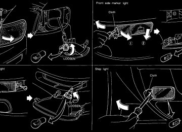
FRONT PERSONAL LIGHT
VANITY MIRROR LIGHT
TRUNK LIGHT
illuminates when the trunk lid is The light opened. When the trunk lid is closed, the light will go off.
IC1019
SIC0186
The light on the vanity mirror will turn on when the cover on the vanity mirror is opened.
IC1163-A
1-23
Z 01.2.1/A32-D X
INTEGRATED HomeLink TRANSMITTER (If so equipped) The Integrated HomeLink Transmitter pro- vides a convenient way to consolidate the functions of up to three individual hand-held transmitters into one built-in device. THE INTEGRATED HomeLink TRANSMITTER: I will operate garage doors, gates, home/ office lighting systems and security sys- tems by storing and transmitting the pro- gramming information of your current hand- held transmitters.
I is built-in and powered by your vehicle’s battery and charging system. No separate batteries are necessary.
Do not use this Integrated HomeLink Transmitter with any garage door opener that lacks safety stop and re- verse features as required by federal safety standards (these standards be- came effective for models manufactured after April 1, 1982). A garage door opener which cannot “detect” an object in the path of a closing garage door and then automatically stop and reverse the door, does not meet current federal safety standards. Using a garage door opener without these features increases the risk of serious injury or death.
PROGRAMMING THE HomeLink TRANSMITTER
SIC0696
During the programming procedure your garage door or security gate will open and close (if the transmitter is within range). Make sure that people or objects are clear of the garage door, gate, etc. that you are programming.
Your vehicle’s engine should be turned off while programming your transmitter.
1-24
Z 01.2.1/A32-D X
The Integrated HomeLink Transmitter may not work with older garage door openers that do not meet current Fed- eral Consumer Safety Standards.
1. Test the Integrated HomeLink Transmitter by pressing any button. The red indicator light should come on. If you have previously programmed a button proceed to step 3.
2. Clear all channels on the Integrated HomeLink Transmitter by holding down both outside buttons (#1 & #3) until the red light begins to flash rapidly (approximately 20 seconds). Then release both buttons.
3. Select which of
the three Integrated HomeLink Transmitter buttons you want to program.
4. Hold your hand-held transmitter against the bottom surface of the Integrated HomeLink Transmitter so that you can still see the
red indicator light.
5. Press the desired button until the red indi- cator light flashes slowly. Do not release the button. Continue holding and press the hand-held transmitter button through step 6.
6. Hold
until
buttons
Transmitter
the both down light on the Integrated red indicator flashes rapidly HomeLink (This may take 1-90 seconds). Then re- lease both buttons. The rapid flashing means that the transmitter has been suc- cessfully programmed to match your hand- held transmitter. You can now use the Integrated HomeLink Transmitter instead of your hand-held transmitter.
to 1992, D.O.C.
Note to Canadian users: Prior regulations required many hand-held transmitters to stop transmit- ting after one or two seconds, even though you continue to hold down the button. If you think you have one of these hand-held transmitters, you should press and re-press the transmitter button every 2 seconds without ever releasing the integrated HomeLink Transmitter button. The indicator light on the Integrated HomeLink Transmitter should blink rapidly indicating a successful programming procedure. If it re- turns to the slow blink of program mode, continue to periodically reactivate your hand- held transmitter until a successful program- ming procedure is indicated by the rapidly flashing indicator light.
OPERATING THE TRANSMITTER To operate, simply press the appropriate but- ton on the Integrated HomeLink Transmitter. The red indicator light illuminates while the signal is being transmitted. The effective trans- mission range of the Integrated HomeLink Transmitter may differ from your hand-held transmitter. PROGRAMMING PROBLEM DIAGNOSIS Be sure to keep your original hand-held trans- mitter for possible reprogramming if neces- sary. I Make sure batteries in the hand-held trans-
mitter are fully charged.
I Hold your hand-held transmitter against the bottom surface Integrated HomeLink Transmitter so that you can still see the red indicator light.
the
of
I Hold buttons for duration of the program-
ming without interruption.
I Rotate your hand-held transmitter end- over-end and program again. For best re- sults, place the end opposite the battery compartment Integrated
against
the
1-25
Z 01.2.1/A32-D X
HomeLink ming.
Transmitter when program-
SPA0609
ROLLING CODES (If so equipped) If your hand held transmitter appears to train to the HomeLink Transmitter, but does not open your garage door, and your garage door opener was manufactured after 1995, your garage door opener may have a “Code Pro- tected” or “Rolling Code” feature. This type of system will change the “code” of your garage door opener every time you open or close your garage door. To determine if you have one of these sys- tems, depress the button on the HomeLink Transmitter that you have just programmed. If the LED on the HomeLink Transmitter
1-26
flashes rapidly for 1 to 2 seconds, then re- mains on, your garage door opener has a rolling code system.
To operate your “Rolling Code” garage door opener from your HomeLink Transmitter, fol- low these steps:
1. Program your hand held transmitter to the HomeLink Transmitter by following the procedures outlined above (if not yet pro- grammed).
2. Program your garage door opener receiver to recognize your HomeLink Transmitter (The HomeLink Transmitter follows the same procedure to train to the receiver as your hand held transmitter did when it was first installed):
a) Remove the cover panel from your ga- rage door opener receiver. The receiver should be located by the garage door opener motor.
b) Locate the training button on the garage door opener receiver. The exact location and color of the button may vary by garage door opener brand. If you have difficulty locating the training button, ref- erence opener manual. If you have difficulty program- ming your garage door opener equipped
garage
door
your
Z 01.2.1/A32-D X
15. Operation is subject to the following two conditions: (1) This device may not cause harmful interference and (2) This device must accept any interference that may be received, including interference that may cause undesired operation. The transmitter has been tested and com- plies with FCC and DOC/MDC rules. Changes or modifications not expressly approved by the party responsible for com- pliance could void the user’s authority to operate the device. DOC: ISTC 1763K1313
FCC I.D.: CB2V67690with a rolling code system to recognize the HomeLink Transmitter with the “Rolling Code” feature, call NISSAN Consumer Affairs Department.
c) Press the training button on the garage door opener receiver for 1 to 2 seconds. d) Return to the HomeLink Transmitter in the vehicle, and depress the pro- grammed HomeLink button for the du- ration of the fast blink on the HomeLink Transmitter (1 to 2 seconds). Release the button, and re-press to confirm that the system has trained.
e) Your garage door opener should now recognize your HomeLink Transmitter. You may use either your HomeLink Transmitter or your original hand held transmitter to open your garage door.
CLEARING THE PROGRAMMING INFORMATION Should you sell your vehicle, be sure to clear the channels of the Integrated HomeLink Transmitter. To clear the channels, simulta- neously hold down the outside two buttons (#1
& #3) until the red indicator light begins to flash rapidly (approximately 20 seconds). This will clear all three buttons. Individual buttons can- not be cleared, but can be reprogrammed at any time by following the programming proce- dures described above. IF YOUR VEHICLE IS EVER STOLEN If your vehicle has been stolen, you should change the codes of any device that was Integrated HomeLink Transmitter as soon as possible. Consult the owners manual of each device, or call the manufacturer or dealer of those de- vices. When your vehicle is recovered, you will need to reprogram the Integrated HomeLink Transmitter with your new transmitter information. FCC Notice: This device complies with FCC rules partprogrammed
into
the
1-27
Z 01.2.1/A32-D X
MEMO
1-28
Z 01.2.1/A32-D X
2 Pre-driving checks and adjustments
Key ............................................................................ 2-2
Door locks ................................................................. 2-2
Multi-remote control system (If so equipped) ........... 2-5
Hood release............................................................. 2-8
Glove box lock .......................................................... 2-8
Trunk lid lock............................................................. 2-9
Fuel filler lid lock ..................................................... 2-10
Seats ....................................................................... 2-12
Supplemental restraint system (Supplemental air bag system) ............................... 2-17
Supplemental air bag warning labels...................... 2-22
Supplemental air bag warning light......................... 2-22
Seat belts ................................................................ 2-24
Child restraints for infants and small children......... 2-31
Tilting steering wheel .............................................. 2-38
Outside mirror remote control ................................. 2-39
Foldable outside mirrors.......................................... 2-39
Inside mirror ............................................................ 2-40Z 01.2.1/A32-D X
KEY
DOOR LOCKS
A key number is only necessary when you have lost all keys and do not have one to duplicate from. If you still have a key, this key can be duplicated by your NISSAN dealer or a lock smith shop.
SPA0083
The master key can be used for all the locks. Record the key number on the key number plate and keep it in a safe place (such as your wallet), NOT IN THE CAR. A key number plate is supplied with your key. Keep the plate in a safe place. NISSAN does not record key num- bers so it is very important to keep track of your key number plate.
SPA0084
Locking front doors with key To lock the door, turn the key towards the front of the vehicle. To unlock, turn it towards the rear. Locking the front door will simultaneously lock the other doors.
2-2
Z 01.2.1/A32-D X
I Always have the doors locked while driving. Along with the use of seat belts, this provides greater safety in the event of an accident by helping to prevent persons from being thrown from the vehicle. This also helps keep children and others from unintention- ally opening the doors, and will help keep out intruders.
I Before opening any door, always look
for and avoid oncoming traffic.
I Do not leave children unattended in- side the vehicle. They could unknow- ingly activate switches or controls. Unattended children could become involved in serious accidents.
SPA0086
CHILD SAFETY REAR DOOR LOCK Child safety locking helps prevent doors from being opened accidentally, especially when small children are in the vehicle. When the lever is in the lock position, the rear door can be opened only from the outside.
SPA0085
Locking the doors without key To lock from the outside without a key, move the inside lock knob to the “LOCK” position. Then close the door. When locking the door this way, be certain not to leave the key inside the vehicle. The inside lock knob cannot be set to the “LOCK” position with the front doors open and with the key in the ignition.
2-3
Z 01.2.1/A32-D X
the “LOCK” position will lock all doors.
SPA0087
POWER DOOR LOCK The power door lock system allows you to lock or unlock all doors simultaneously. I Turning the front door key to the front of the
vehicle will lock all doors.
I Turning the front door key one time to the rear of the vehicle will unlock the corre- sponding door. From that position, return- ing the key to Neutral (where the key can only be removed and inserted.) and turning it to the rear again within 5 seconds will unlock all doors.
I Pushing the front door inside lock knob to
SPA0088
I Operating the lock-unlock switch will lock orunlock all doors.
I Before opening any door, always look
for and avoid oncoming traffic.
I Do not leave children unattended in- side the vehicle. They could unknow- ingly activate switches or controls. Unattended children could become involved in serious accidents.
2-4
Z 01.2.1/A32-D X
MULTI-REMOTE CONTROL SYSTEM (If so equipped)
It is possible to lock/unlock all doors, to open the driver’s and front passenger’s windows, to release the trunk lid and to turn on or off the interior light by using the remote controller from outside the car. Be sure to remove the key from the vehicle before locking the doors and leaving it. The remote controller can operate at a dis- tance of approximately 49 ft (15 m) from the vehicle. (The effective distance depends upon the conditions around the vehicle.) As many as four remote controllers can be used with one vehicle. For information con- cerning the purchase and use of additional remote controllers, contact your NISSAN dealer.
Listed below are conditions or occur- rences which will damage the remote controller. I Do not allow the remote controller to
become wet.
I Do not drop the remote controller. I Do not strike the remote controller
sharply against another object.
SPA0277
I Do not place the remote controller for
2-5
Z 01.2.1/A32-D X
an extended period in an area where temperatures exceed 140°F (60°C).
DOOR LOCK OPERATION 1. Remove the ignition key.
2. Close all doors.
3. Push the lock button on the remote control-
ler.
4. The hazard indicator flashes twice. 5. All doors will lock. Although door locking with the remote control- ler can be confirmed by looking at the hazard indicator, always check to be sure that the doors are properly locked before leaving your vehicle. DOOR UNLOCK OPERATION 1. Push the unlock button on the remote con-
troller.
2. Only the driver side door will unlock. Push the unlock button on the remote controller again within 5 seconds. All doors will unlock.
3. The interior light will stay on for 30 seconds when the interior light switch is in the center “q” position.
The interior light can be turned off without waiting for 30 seconds by inserting the key into the ignition and turning it “ON” or by locking the doors with the remote controller or by pushing the interior light button. OPENING THE DRIVER’S AND FRONT PASSENGER’S WINDOW 1. Push the unlock button on the remote con- troller for longer than 1.5 seconds after the driver’s door is unlocked.
2. The driver’s and front passenger’s window
will open. The driver’s and front passenger’s window will also open after all doors are unlocked with the remote controller. The driver’s and front passenger’s win- dow cannot be closed by using the re- mote controller.
TRUNK LID OPENER OPERATION 1. Push the trunk lid release button on the remote controller for longer than 0.5 sec- ond.
2. The trunk lid will open. The trunk lid will not open when the trunk lid cancel lever is in the “CANCEL” position. It can be opened only with the key.
2-6
PANIC ALARM OPERATION If you are near your vehicle and feel threat- ened, you may activate the alarm to call atten- tion as follows: 1. Push the panic alarm button on the remote
controller for longer than 1.5 seconds.
2. The theft warning alarm and headlight will
stay on for 30 seconds.
3. The alarm will stop when any of the key functions on the remote controller are used.
The remote controller will not function. I When the key is inserted into the key
switch.
I When the battery in the remote control-
ler is dead.
I The distance between the remote con- troller and vehicle is more than approx. 49 ft (15 m).
Z 01.2.1/A32-D X
Recommended battery: Sanyo CR2025 or equivalent
that may cause undesired operation of the device.
3. Close the lid securely.
4. Push the remote controller button two or
three times to check its operation.
If the battery is removed for any reason other than replacement, perform step 4
above. I An improperly disposed battery can harm the environment. Always confirm local regulations for battery disposal.I The remote controller is water-resistant; however, if it does get wet, immediately wipe completely dry.
I When changing batteries, do not let dust
or oil get on the controller.
FCC Notice: Changes or modifications not expressly approved by the manufacturer compliance could void the user’s authority to operate the equipment. This device complies with Part 15 of the FCC Rules and RSS-210 of Industry Canada. Operation is subject to the following two conditions: (1) This de- vice may not cause harmful interference, and (2) this device must accept any inter- including interference ference received, 2-7
Z 01.2.1/A32-D X
SPA0090
BATTERY REPLACEMENT Replace the battery as follows:
1. Open the lid using a suitable tool.
2. Replace the battery with a new one.
HOOD RELEASE
GLOVE BOX LOCK
1. Pull the hood lock release handle q1
lo- cated below the instrument panel; the hood will then spring up slightly.
2. Pull the lever q2 at the front of the hood with
your fingertips and raise the hood.
3. When closing the hood, slowly close the
hood and make sure it locks into place.
SPA0466
SPA0092
I Make sure the hood is completely closed and latched before driving. Failure to do so could cause the hood to fly open and result in an accident. I If you see steam or smoke coming to
from the engine compartment, avoid injury, do not open the hood.
When locking or unlocking the glove box, use the master key. The glove box may be opened by pulling the handle.
Keep glove box lid closed while driving to help prevent injury in an accident or a sudden stop.
2-8
Z 01.2.1/A32-D X
TRUNK LID LOCK
push the trunk lid down securely. Type B The trunk lid release button is located under the driver’s arm rest. To open the trunk lid, push the release button. To close, push the trunk lid down securely.
SPA0093
Trunk lid release operation Type A
The trunk lid release lever is located on the outside of the driver’s seat. To open the trunk lid, pull up the trunk lid release lever. To close,
SPA0094
Key operation To open the trunk lid, turn the key clockwise. To close, lower and push the trunk lid down securely.
Do not drive with the trunk lid open. This could allow dangerous exhaust gases to be drawn into the vehicle. See “Exhaust Gas” in the “Starting and driving” section.
2-9
Z 01.2.1/A32-D X
FUEL FILLER LID LOCK
SPA0095
SPA0096
SPA0119
OPENER CANCEL LEVER FOR TRUNK LID When the lever is in the “CANCEL” position, the trunk lid cannot be opened with the trunk lid release lever or handle. It can be opened only with the key.
Opener lever Type A To open the fuel filler lid, pull the opener lever. To lock, close the fuel filler lid securely. Type B To open the fuel filler lid, push the opener lever down. To lock, close the fuel filler lid securely.
FUEL FILLER CAP The fuel filler cap is a screw-on ratcheting type. Tighten the cap clockwise until ratcheting clicks are heard.
I Gasoline is extremely flammable and highly explosive under certain condi- tions. You could be burned or seri- ously injured if it is misused or mis- handled. Always stop the engine and do not smoke or allow open flames or
2-10
Z 01.2.1/A32-D X
sparks near the vehicle when refuel- ing.
I Fuel may be under pressure. Turn the cap one-half turn and wait for any “hissing” sound to stop, to prevent fuel from spraying out and possible personal injury. Then remove the cap. I Use only a genuine NISSAN fuel filler cap as a replacement. It has a built-in safety valve needed for proper opera- tion of the fuel system and emission control system. An incorrect cap can result in a serious malfunction and possible injury.
If fuel is spilled on the vehicle body, flush it away with water to avoid paint damage.
If the fuel filler cap is not tightened prop- erly, the malfunction indicator light (MIL) may come on.
Put the fuel filler cap on the cap holder while refueling.
SPA0120
2-11
Z 01.2.1/A32-D X
SEATS
SEAT ADJUSTMENT
I Do not adjust the driver’s seat while driving. The seat may move suddenly and could cause loss of control of the vehicle.
I After adjustment, gently rock in the is securely
to make sure it
seat locked.
SPA0472
SPA0473
I For most effective protection when the vehicle is in motion, the seat should be upright. Always sit well back in the seat and adjust the seat belt properly. See “Precautions on seat belt usage” later in this chapter.
I Do not ride in a moving vehicle when the seatback is reclined. This can be dangerous. The shoulder belt will not be against your body. In an accident you could be thrown into it and re- ceive neck or other serious injuries. You could also slide under the lap belt and receive serious internal injuries.
2-12
Z 01.2.1/A32-D X
Forward and backward Pull the lever up while you slide the seat forward or backward to the desired position. Release the lever to lock the seat in position. Reclining To recline the seatback, pull the lever up and lean back. To bring the seatback forward again, pull the lever and move your body forward. The seatback moves forward.
SPA0097
SPA0099
Seat lifter (Driver’s seat) Turn either dial to adjust the angle and height of the seat cushion to the desired position.
2-13
Z 01.2.1/A32-D X
Forward and backward Moving the switch forward or backward will slide the seat forward or backward to the desired position. Reclining Move the recline switch backward until the desired angle is obtained. To bring the seat- back forward again, move the switch forward and move your body forward. The seatback will move forward.
POWER SUPPORT SEAT (If so equipped)
I Do not adjust the driver’s seat while driving in order that full attention may be given to the driving operations.
I Do not leave children unattended in- side the vehicle. They could unknow- ingly activate switches or controls.
SPA0098
Unattended children could become involved in serious accidents.
Operating tips I The motor has an auto-reset overload pro- tection circuit. the motor stops during operation, wait 30 seconds, then reactivate the switch.
If
I Do not operate the power support seat for a long period of time when the engine is off. This will discharge the battery.
2-14
Z 01.2.1/A32-D X
SPA0100
SPA0467
SPA0014
Seat lifter (Driver’s seat) Push the front or rear end of the switch up or down to adjust the angle and height of the seat cushion.
Lumbar support (Driver’s seat) Turn the lever forward or backward to adjust the seat lumbar area.
HEAD RESTRAINT To raise the head restraint, just pull it up. To lower, push the lock knob and push the head restraint down.
Adjust the top of the head restraints level with the top of your ears.
Head restraints should be adjusted properly as they may provide significant protection against injury in an accident. Do not remove them. Check the adjust-
2-15
Z 01.2.1/A32-D X
ment after someone else uses the seat.
are able to gain access to the trunk room.
SPA0102
REAR SEAT Center armrest and tray Pull the armrest forward and lay it horizontal. Then release the lever (inset) and pull the tray forward (If so equipped). In this condition you
2-16
Z 01.2.1/A32-D X
SUPPLEMENTAL RESTRAINT SYSTEM (SUPPLEMENTAL AIR BAG SYSTEM) This Supplemental Restraint System section contains important information concerning the driver and passenger supplemental air bags. The Supplemental Restraint System Air Bag can help reduce impact force to the driver and to the front passenger in certain frontal colli- sions. The supplemental air bags are designed to supplement the crash protection provided by the driver and passenger seat belts and are not a substitute for them. The seat belts should always be correctly worn and the driver and front passenger seated a suitable distance away from the steering wheel and instrument panel. (See “Seat belts” for instructions and precautions on seat belt usage.) After turning the ignition key to the “ON” position, the supplemental air bag warning light illuminates. The supplemental air bag warning light will turn off after about 7
seconds if the system is operational.SPA0504
SPA0505
I The supplemental air bags ordinarily will not inflate in the event of a side impact, rear impact, roll over, or lower severity frontal collision. Al- ways wear your seat belts to help reduce the risk or severity of injury in various kinds of accidents.
I The seat belts and the supplemental air bags are most effective when you are sitting back and upright in the seat. Supplemental air bags inflate with great If you are unre- strained, leaning forward, sitting sideways or out of position in any way, you are at greater risk of injury or death in a crash and may also receive serious or fatal injuries from the supplemental air bag if you are up
force.
2-17
Z 01.2.1/A32-D X
SPA0476
SPA0477
SPA0478
against it when it inflates. Always sit back against the seatback and as far away as practical from the steering wheel or instrument panel. Always use the seat belts.
I Keep hands on the outside of the steering wheel. Placing them inside the steering wheel rim could increase the risk that they are injured when the supplemental air bag inflates.
2-18
Z 01.2.1/A32-D X
SPA0479
SPA0480
SPA0482
I Never let children ride unrestrained. Do not attempt to hold them in your lap or arms. Some examples of dan- gerous riding positions are shown in the previous illustrations.
I Children may be severely injured or killed when the supplemental air bag inflates if they are not properly re- strained.
I Also, never install a rear-facing child restraint in the front seat. An inflating supplemental air bag could seriously injure or kill your child. See “Child restraints for infants and small chil- dren” for details.
SPA0481
SPA0483
2-19
Z 01.2.1/A32-D X
The seat belts should be correctly worn and the driver and passenger seated upright as far as practical away from the steering wheel or dashboard. Since the supplemental air bag inflates quickly in order to help protect the occupant, the force of the supplemental air bag inflating can increase the risk of injury if the occupant is too close to or is against the supplemental air bag module during inflation.
The supplemental air bag will deflate quickly after a collision. After turning the ignition key to the “ON” position, the supplemental air bag warning light illuminates. The supplemental air bag warning light will turn off after about 7
seconds if the system is operational.I Do not place any objects on the steer- ing wheel pad or on the instrument panel. Also, do not place any objects between any occupant and the steer- ing wheel or instrument panel. Such objects may become dangerous pro- jectiles and cause injury if the supple- mental air bag inflates.
I Right after inflation, several supple-
the steering wheel;
Supplemental air bag system The driver supplemental air bag is located in the center of the front passenger supplemental air bag is mounted in the dashboard above the glove box. The supplemental air bag system is designed to inflate in higher severity frontal collisions, al- though it may inflate if the forces in another type of collision are similar to those of a higher severity frontal impact. It may not inflate in certain frontal collisions. Vehicle damage (or lack of it) is not always an indication of proper supplemental air bag operation. When the supplemental air bag inflates, a fairly
SPA0103A
loud noise may be heard, followed by release of smoke. This smoke is not harmful and does not indicate a fire, but care should be taken not to intentionally inhale it, as it may cause irrita- tion and choking. Those with a history of breathing trouble should get fresh air promptly.
Supplemental air bags, along with the use of seat belts, help to cushion the impact force on the face and chest of the occupant. They can help save lives and reduce serious injuries. However, an inflating supplemental air bag may cause facial abrasions or other injuries. Supplemental air bags do not provide restraint to the lower body.
2-20
Z 01.2.1/A32-D X
I Work around and on the supplemen- tal air bag system should be done by an authorized NISSAN dealer. Instal- lation of electrical equipment should also be done by an authorized NISSAN dealer. The SRS wiring har- nesses should not be modified or disconnected. Unauthorized electri- cal test equipment and probing de- vices should not be used on the supplemental air bag system.
I The SRS wiring harnesses are cov- ered with yellow insulation either just before the harness connectors or for the complete harness, for easy identification.
When selling your vehicle, we request that you inform the buyer about the supplemental air bag system and guide the buyer to the appro- priate sections in this Owner’s Manual.
mental air bag system components will be hot. Do not touch them; you may severely burn yourself.
I No unauthorized changes should be made to any components or wiring of the supplemental air bag system. This is to prevent accidental inflation of the supplemental air bag or dam- age to the supplemental air bag sys- tem.
I Do not make unauthorized changes to your vehicle’s electrical system, suspension system or front end structure. This could affect proper operation of the supplemental air bag system.
I Tampering with the supplemental air bag system may result in serious personal injury. Tampering includes changes to the steering wheel and the instrument panel assembly by placing material over the steering wheel pad and above the dashboard, or by installing additional trim mate- rial around the supplemental air bag system.
2-21
Z 01.2.1/A32-D X
SUPPLEMENTAL AIR BAG WARNING LABELS
SUPPLEMENTAL AIR BAG WARNING LIGHT
Warning labels about the supplemental air bag system are placed in the vehicle.
SPA0104A
SPA0105
The supplemental air bag light, displaying “AIR BAG” in the instrument panel, monitors the circuits of the supplemental air bag. The cir- cuits monitored by the supplemental air bag light are the diagnosis sensor unit, supplemen- tal air bag modules and all related wiring. When the ignition key is in the “ON” or “START” position, the supplemental air bag light will illuminate for about 7 seconds and then turn off. This means the system is opera- tional.
2-22
Z 01.2.1/A32-D X
should be inspected by an authorized NISSAN dealer if there is any damage to the front end portion of the vehicle. I If you need to dispose of a supple- mental air bag or scrap the vehicle, contact an authorized NISSAN dealer. Correct supplemental air bag dis- posal procedures are set forth in the appropriate NISSAN Service Manual. Incorrect disposal procedures could cause personal injury.
If any of the following conditions occurs, the supplemental air bag needs servicing:
1. The supplemental air bag light goes off
within 7 seconds.
2. The supplemental air bag light flashes in- termittently or remains on (after 7 seconds).
3. The supplemental air bag light does not
come on at all.
Under these conditions, the Supplemental Re- straint System Air Bag may not operate prop- erly. It must be checked and repaired.
Take your vehicle to the nearest authorized NISSAN dealer.
inflation has occurred. Repair and replace- ment of the supplemental air bag system should be done only by authorized NISSAN dealers. To ensure long-term functioning, the sys- tem must be inspected 10 years after the date of manufacture noted on the certifica- tion label located on the driver side center pillar.
When maintenance work is required on the vehicle, the supplemental air bag system and related parts should be pointed out to the person conducting the maintenance. The igni- tion key should always be in the “LOCK” position when working under the hood or in- side the vehicle.
If the supplemental air bag warning light is on, it could mean that the supplemen- tal air bag will not operate in an accident.
Repair and replacement procedure The supplemental air bag system is designed to inflate on a one-time-only basis. As a re- minder, unless it is damaged, the supplemen- tal air bag light will remain illuminated after
I Once the supplemental air bag has inflated, the supplemental air bag module will not function again and must be replaced. The supplemental air bag module should be replaced by an authorized NISSAN dealer. The supplemental air bag module cannot be repaired.
I The supplemental air bag system
2-23
Z 01.2.1/A32-D X
SEAT BELTS
PRECAUTIONS ON SEAT BELT USAGE Your chances of being injured or killed in an accident and/or the severity of injury may be greatly reduced if you are wearing your seat belt and it is properly adjusted. NISSAN strongly encourages you and all of your pas- sengers to buckle up every time you drive, even if your seating position includes a supple- mental air bag. Some states, provinces or territories re- quire that seat belts be worn at all times when a vehicle is being driven.
SPA0506
SPA0485
I Every person who drives or rides in this vehicle should use a seat belt at all times. Children should be properly restrained and, in a child restraint.
if appropriate,
I The belt should be adjusted properly and to a snug fit. Failure to do so may reduce the effectiveness of the entire restraint system and increase the
2-24
chance or severity of injury in an accident. Serious injury or death can occur if the seat belt is not worn properly.
I Always route the shoulder belt over your shoulder and across your chest. Never run the belt behind your backs under your arm or across your neck. The belt should be away from your face and neck, but not falling off your shoulder.
I Position the lap belt as low and snug
Z 01.2.1/A32-D X
I Never carry more people in the ve-
hicle than there are seat belts.
I If the seat belt warning lamp glows continuously while the ignition is turned “ON” with all doors closed and all seat belts fastened, it may indicate a malfunction in the system. Have the system checked by your NISSAN dealer.
I All seat belt assemblies including re- tractors and attaching hardware should be inspected by your NISSAN dealer after any collision. NISSAN recommends that all seat belt assem- blies in use during a collision be replaced unless the collision was mi- nor and the belts show no damage and continue to operate properly. Seat belt assemblies not in use dur- ing a collision should also be in- spected and replaced if either dam- age or improper operation is noted.
CHILD SAFETY Children need adults to help protect them.
Infants and children need special pro- tection. The vehicle’s seat belts may not fit them properly. The shoulder belt may come too close to the face or neck. The lap belt may not fit over their small hip bones. In an accident, an improperly fitting seat belt could cause serious or fatal injury. Always use appropriate child restraints.
All U.S. states and provinces of Canada re- quire the use of approved child restraints for infants and small children. (See “Child re- straints for infants and small children” later in this section.)
In addition, there are many types of child restraints available for larger children which should be used for maximum protection. Infant or small child NISSAN recommends that infants or small children be placed in child restraints that com- ply with Federal Motor Vehicle Safety Stan- dards or Canadian Motor Vehicle Safety Stan- dards. You should choose a child restraint that fits your vehicle and always follow the manu-
2-25
Z 01.2.1/A32-D X
SPA0486
as possible AROUND THE HIPS, NOT THE WAIST. A lap belt worn too high could increase the risk of internal injuries in an accident.
I Be sure the seat belt tongue is se- curely fastened to the proper buckle. I Do not wear the belt inside out or twisted. Doing so may reduce its ef- fectiveness.
I Do not allow more than one person to
use the same belt.
facturer’s instructions for installation and use. Children Children who are too large for child restraint systems should be seated and restrained by the seat belts which are provided. NISSAN recommends that children sit in the rear seat if possible. According to accident statistics, children are safer when properly restrained in the rear seat than in the front seat. If the child’s seating position has a shoulder belt that fits close to the face or neck, the use of a booster seat (commercially available) may help overcome this. The booster seat should raise the child so that is properly positioned across the top, middle portion of the shoulder and the lap belt is low on the hips. The booster seat should fit the vehicle seat and have a label certifying that it complies with Federal Motor Vehicle Safety Standards or Canadian Motor Vehicle Safety Standards. Once the child has grown so the shoulder belt is no longer on or near the face and neck, use the shoulder belt without the booster seat.
the shoulder belt
Never let a child stand or kneel on any seat and do not allow a child in the cargo areas while the vehicle is moving. The child could be seriously injured or killed in an accident.
PREGNANT WOMEN NISSAN recommends that pregnant women use seat belts. Contact your doctor for specific recommendations. The lap belt should be worn snug and positioned as low as possible around the hips, not the waist. INJURED PERSONS NISSAN recommends that injured persons use seat belts, depending on the injury. Check with your doctor for specific recommendations.
3-POINT TYPE SEAT BELT WITH RETRACTOR
SPA0492
Every person who drives or rides in this vehicle should wear a seat belt at all times.
Fastening the belts 1. Adjust the seat.
2-26
Z 01.2.1/A32-D X
and adjust the seat belt properly.
SPA0493
Do not ride in a moving vehicle when the seatback is reclined. This can be dan- gerous. The shoulder belt will not be against your body. In an accident you could be thrown into it and receive neck or other serious injuries. You could also slide under the lap belt and receive se- rious internal injuries.
For most effective protection when the vehicle is in motion, the seat should be upright. Always sit well back in the seat
PD1024M
2. Slowly pull the seat belt out of the retractor and insert the tongue into the buckle until it snaps.
The retractor is designed to lock during a sudden stop or on impact. A slow pulling motion will permit the belt to move, and allow you some freedom of movement in the seat. 3. Position the lap belt portion low and snug
on the hips as shown.
4. Pull the shoulder belt portion toward the
retractor to take up extra slack.
The front passenger side seat belt and rear
2-27
Z 01.2.1/A32-D X
3-point seat belts have a cinching mechanism for child seat installation. It is referred to as the automatic locking mode. When the cinching mechanism is activated the seat belt cannot be withdrawn again until the seat belt tongue is detached from the buckle and fully retracted. Refer to “Child restraints for infants and small children” later in this section for more information. The automatic locking mode should be used only for child seat installation. During normal seat belt use by a passenger, the locking mode should not be activated. If it is activated it may cause uncomfortable seat belt tension. Unfastening the belts To unfasten the belt, press the button on the buckle. The seat belt will automatically retract.
Checking seat belt operation (3-point type with retractor) Your seat belt retractors are designed to lock belt movement using two separate methods: 1) When the belt is pulled quickly from the
retractor.
2) When the vehicle slows down rapidly. You can check their operation as follows: I Grasp the shoulder belt and pull quickly forward. The retractor should lock and re- strict further belt movement.
If the retractor does not lock during this check or if you have any questions about belt opera- tion, see your NISSAN dealer.
PD1321-A
Shoulder belt height adjustment