- 2012 Nissan Frontier Owners Manuals
- Nissan Frontier Owners Manuals
- 2003 Nissan Frontier Owners Manuals
- Nissan Frontier Owners Manuals
- 2004 Nissan Frontier Owners Manuals
- Nissan Frontier Owners Manuals
- 2009 Nissan Frontier Owners Manuals
- Nissan Frontier Owners Manuals
- 2001 Nissan Frontier Owners Manuals
- Nissan Frontier Owners Manuals
- 2010 Nissan Frontier Owners Manuals
- Nissan Frontier Owners Manuals
- 1996 Nissan Frontier Owners Manuals
- Nissan Frontier Owners Manuals
- 2005 Nissan Frontier Owners Manuals
- Nissan Frontier Owners Manuals
- 2007 Nissan Frontier Owners Manuals
- Nissan Frontier Owners Manuals
- 2008 Nissan Frontier Owners Manuals
- Nissan Frontier Owners Manuals
- 1999 Nissan Frontier Owners Manuals
- Nissan Frontier Owners Manuals
- 2002 Nissan Frontier Owners Manuals
- Nissan Frontier Owners Manuals
- 2000 Nissan Frontier Owners Manuals
- Nissan Frontier Owners Manuals
- 2011 Nissan Frontier Owners Manuals
- Nissan Frontier Owners Manuals
- 1998 Nissan Frontier Owners Manuals
- Nissan Frontier Owners Manuals
- 1997 Nissan Frontier Owners Manuals
- Nissan Frontier Owners Manuals
- 2006 Nissan Frontier Owners Manuals
- Nissan Frontier Owners Manuals
- Download PDF Manual
-
This light comes on when the automatic transmission oil temperature is too high. If the light comes on while driving, reduce the vehicle speed as soon as safely possible until the light turns off.
2-8 Instruments and controls
CAUTION
Continued vehicle operation when the A/T oil temperature warning light is on may damage the automatic transmis- sion.
Automatic transmission park model) warning light ( This light indicates that the automatic trans- mission parking function is not engaged. If the transfer control lever is not secured in any drive position while the automatic trans- mission selector lever is in the P (Park) position, the transmission will disengage and the vehicle may move unexpectedly. Shift the transfer control lever into the 2H, 4H, or 4L position when the warning light comes on. c When parking, always make sure that the transfer control lever is in 2H, 4H, or 4L and the parking brake is set.
c If the ATP light is ON, this indicates that the automatic transmission P (Park) po- sition will not function and the transfer lever is in the N (Neutral) position.
c Failure to engage the transfer control lever
in 2H, 4H, or 4L could result in the vehicle moving unexpectedly, resulting in serious personal injury or property damage.
WARNING
c If the ATP light is ON, this indicates that the automatic transmission P (Park) position will not function and the transfer control shift lever is in the N (Neutral) position.
or
Brake warning light
functions for both the parking
This light brake and the foot brake systems. When the ignition key is in the ON position, the light comes on when the parking brake is applied and also warns of a low brake fluid level. If the light comes on while the engine is running with the parking brake not applied, stop the vehicle and perform the following: 1. Check the brake fluid level. Add brake fluid as necessary. See ‘‘Brake and clutch fluid’’ in the ‘‘Do-it-yourself’’ section of this manual.
Z X
2. If the brake fluid level is correct, have the warning system checked by an autho- rized NISSAN dealer.
WARNING
c Your brake system may not be work- ing properly if the warning light is on. Driving could be dangerous. If you judge it to be safe, drive carefully to the nearest service station for repairs. Otherwise have your vehicle towed because driving it could be danger- ous.
c Pressing the brake pedal with the engine stopped and/or low brake fluid level may increase your stop- ping distance and require greater pedal effort as well as pedal travel. c If the brake fluid level is below the MINIMUM or MIN mark on the brake fluid reservoir, do not drive until the brake system has been checked at an authorized NISSAN dealer.
Charge warning light
If this light comes on while the engine is running, it may indicate the charging system
is not functioning properly. Turn the engine off and check the generator belt. If the belt is loose, broken, missing or if the light remains on, see an authorized NISSAN dealer im- mediately.
CAUTION
Do not continue driving if the belt is loose, broken or missing.
‘‘Engine oil’’ in the ‘‘Do-it-yourself’’ section of this manual.
CAUTION
Running the engine with the oil pres- sure warning light on could cause seri- ous damage to the engine almost im- mediately. Turn off the engine as soon as it is safe to do so.
Door open warning light (if so equipped)
This light comes on when any of the doors are not closed securely while the ignition key is in the ON position.
Engine oil pressure warning light
This light warns of low engine oil pressure. If the light flickers or comes on during normal driving, pull off the road in a safe area, stop the engine immediately and call an autho- rized NISSAN dealer. The oil pressure warning light is not designed to indicate a low oil level. Use the dipstick to check the oil level. See
Low fuel warning light
This light comes on when the fuel in the tank is low. Refuel as soon as it is convenient, preferably before the fuel gauge reaches E (Empty). There will be a small reserve of fuel remaining in the tank when the fuel gauge needle reaches E (Empty).
Low washer light (Canada only)
fluid warning
This light comes on when the washer tank fluid is at a low level. Add washer fluid as necessary. See ‘‘Window washer fluid’’ in the ‘‘Do-it-yourself’’ section of this manual.
Instruments and controls 2-9
Z X
Seat belt warning light and chime
The light and chime remind you to fasten your seat belts. The light illuminates when- ever the ignition key is turned to ON or START, and remains illuminated until the driver’s seat belt is fastened. At the same time, the chime sounds for about seven seconds unless the driver seat belt is se- curely fastened. Refer to “Seat belts” in the “Seats, restraints and supplemental air bag systems” section for precautions on seat belt usage.
c The supplemental air bag warning light remains on after approximately 7 sec- onds.
c The supplemental air bag warning light
flashes intermittently.
c The supplemental air bag warning light
does not come on at all.
Unless checked and repaired, the supplemen- tal air bag system and/or the pre-tensioner seat belts may not function properly. For additional details, see the ‘‘Seats, restraints and supplemental air bag systems’’ section of this manual.
Supplemental air bag warning light
When the ignition key is in the ON or START position, the supplemental air bag warning light illuminates for about 7 seconds and then turns off. This means the system is operational. If any of the following conditions occur, the supplemental air bag and pre-tensioner seat belt systems need servicing and your vehicle must be taken to an authorized authorized NISSAN dealer: 2-10 Instruments and controls
WARNING
is on,
If the supplemental air bag warning light the supplemental air bag will not operate in an accident.
it could mean that
Passenger supplemental air bag OFF indicator light (ex- cept Crew Cab models)
The passenger supplemental air bag is equipped with an ON/OFF switch. The switch is located in the center of the instru-
ment panel, near the ashtray. When the switch is turned to the ON position, the passenger supplemental air bag is enabled and could inflate in a frontal collision. When the switch is turned to the OFF position, the passenger supplemental air bag is disabled and will not inflate in a frontal collision. The passenger supplemental air bag OFF indi- cator light on the instrument panel illumi- nates when the passenger supplemental air bag ON/OFF switch is turned to the OFF position. The driver’s side supplemental air bag always remains enabled and is not affected by the passenger supplemental air bag ON/OFF switch. The key for the pas- senger supplemental air bag ON/OFF switch should not be left in the switch. Remove the key after turning the switch in the desired position. Do not leave a key in the switch. See “Passenger supplemental air bag ON/OFF switch and light” in the 9Seats, restraints and supplemental air bag systems9 section for details. INDICATOR LIGHTS
Cruise main switch indicator light (if so equipped)
The light comes on when the cruise control main switch is pushed. The light goes out
Z X
when the main switch is pushed again. While the cruise main switch indicator light comes on, the cruise control system is operational.
Cruise set indicator light (if so equipped)
The light comes on while the vehicle speed is controlled by the cruise control system. If the light blinks while the engine is running, it may indicate the cruise control system is not functioning properly. Have the system checked by your NISSAN dealer.
4-wheel drive indicator light This light comes on when the transfer shift control lever is in the 4H or 4L position.
WARNING
c When parking always make sure the transfer control lever is in the 2H, 4H or 4L position and the parking brake is applied.
c Failure to engage the transfer con- trol lever in 2H, 4H or 4L could result in the vehicle moving unexpectedly, which could cause serious personal injury or property damage.
High beam indicator light
This blue light comes on when the headlight high beams are on and goes out when the low beams are selected. The high beam indicator light also comes on when the passing signal is activated.
Malfunction indicator lamp (MIL)
If this indicator lamp comes on steady or blinks while the engine is running, it may indicate a potential emission control mal- function. The malfunction indicator lamp may also come on steady if the fuel filler cap is loose or missing, or if the vehicle runs out of fuel. Check to make sure the fuel filler cap is installed and closed tightly, and that the vehicle has at least three gallons of fuel in the fuel tank.
the
lamp After a few driving trips, should turn off if no other potential emission control system malfunction exists. Operation The malfunction indicator lamp will come on in one of two ways: c Malfunction indicator lamp on steady − An emission control system malfunction has been detected. Check the fuel filler cap. filler cap is loose or missing, tighten or install the cap and continue to drive the vehicle. The lamp should turn off after a few lamp does not driving trips. If the turn off after a few driving trips, have the vehicle inspected by an authorized NIS- SAN dealer. You do not need to have your vehicle towed to the dealer.
the fuel
If
c Malfunction indicator lamp blinking − An engine misfire has been detected which may damage the emission control sys- tem. To reduce or avoid emission control system damage: c do not drive at speeds above 45 MPH
(72 km/h).
c avoid hard acceleration or deceleration. c avoid steep uphill grades. c if possible, reduce the amount of cargo Instruments and controls 2-11
Z X
CHIMES Brake pad wear warning The disc brake pads have audible wear warnings. When a brake pad requires re- placement, it makes a high pitched scraping sound when the vehicle is in motion whether or not the brake pedal is depressed. Have the brakes checked as soon as possible if the warning sound is heard. Key reminder chime The chime sounds when the driver’s door is opened and the key is left in the ignition switch. Take the ignition key when you leave the vehicle. Light reminder chime A chime sounds if is opened with the headlight switch on unless the ignition key is in the ON position. Turn the headlight switch off when you leave the vehicle.
the driver’s door
being hauled or towed.
The malfunction indicator lamp may stop blinking and come on steady. Have the vehicle inspected by an autho- rized NISSAN dealer. You do not need to have your vehicle towed to the dealer.
CAUTION
Continued vehicle operation without having the emission control system checked and repaired as necessary could lead to poor driveability, reduced fuel economy, and possible damage to the emission control system.
Overdrive off indicator light (automatic transmission only)
This light comes on when the overdrive switch is pushed to the OFF position.
Turn signal/hazard indicator lights
These lights flash when the turn signal switch or hazard switch is turned on.
2-12 Instruments and controls
SECURITY SYSTEM
IC0005
VEHICLE SECURITY SYSTEM (if so equipped) The vehicle security system provides visual and audio alarm signals if parts of the vehicle are disturbed.
Z X
LIC0071
Security indicator light The security indicator light shows the status of the vehicle security system. The light operates whenever the ignition switch is in the LOCK, OFF, or ACC posi- tion. The vehicle security system has four phases. For each phase the operation of the security indicator light is different.
How to activate the vehicle security system 1. Close all windows. (The system can be the windows are
activated even if open.)
2. Remove the key from the ignition switch. 3. Close the hood and all doors. The doors can be locked using the key, power door lock switch or multi-remote controller. Multi-remote controller operation: c Push the LOCK button on the multi- remote controller. All doors lock. The hazard lights flash twice and the horn beeps once to indicate all doors are locked.
c When the LOCK button is pushed with all doors locked, the hazard lights flash twice and the horn beeps once as a reminder that the doors are already locked. The horn may or may not beep once. Refer to ‘‘silencing the horn beep feature’’ later in this section.
4. Confirm that
the SECURITY indicator light comes on. The SECURITY light glows for about 30 seconds and then Instruments and controls 2-13
Z X
LIC0053
How to stop the alarm The alarm stops only by unlocking a door with the key or by pressing the UNLOCK button on the multi-remote controller. The alarm does not stop if the ignition switch is turned to ACC or ON position.
begins to flash once every three seconds. The system is now activated. If, during this 30 second time period, a door is unlocked by the key or the multi-remote controller, or the ignition key is turned to ACC or ON, the system will not activate. c If the key is turned slowly when lock- ing the door, the system may not acti- vate. Furthermore, if the key is turned excessively to the unlock position, the system may be deactivated when the key is removed. If the indicator light fails to glow for 30 seconds, unlock the door once and lock it again.
c Even when the driver and/or passen- gers are in the vehicle, the system will activate with doors, and hood locked and with the ignition key in the OFF position. Turn the ignition key to ACC or ON to turn the system off.
The vehicle security system is NOT acti- vated if one of the following occurs: c A door is unlocked or the ignition key is turned to the ACC or ON position during the 30 seconds in which the SECURITY light stays on.
c The SECURITY light blinks at a steady 2-14 Instruments and controls
1/2 second on - 1/2 second off rate (a door, or the hood is open and the key is not in the ACC or ON position). When the ignition key is turned to the ACC or ON position, the SECURITY light turns off. Vehicle security system operation The vehicle security system emits the fol- lowing alarm: c The headlights blink and the horn sounds intermittently. In addition, the starter mo- tor does not operate.
c The alarm automatically turns off after 50
seconds. However, the alarm reactivates if the vehicle is tampered with again. The alarm can be shut off by unlocking a door with the key or by pressing the UNLOCK button on the multi-remote controller.The alarm is activated by: c opening a door without using the key (even if the door is unlocked by releasing the inside lock knob).
c opening the hood.
Z X
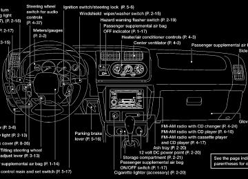
WINDSHIELD WIPER AND WASHER SWITCH
The hazard lights will quickly flash once and the horn will sound once to confirm that the horn beep feature has been reactivated. Deactivating the horn beep feature does not silence the horn if the alarm is triggered. If the system does not operate as de- scribed above, have it checked by an authorized NISSAN dealer.
AIC1084
Instruments and controls 2-15
Z X
WIC0060
Silencing the horn beep feature If desired, the horn beep feature can be deactivated using the multi-remote controller. To deactivate: Press and hold the LOCK and UNLOCK buttons for at least two seconds. The hazard lights will quickly flash three times to confirm that the horn beep feature has been deactivated. To activate: Press and hold the LOCK and UNLOCK buttons for at least two seconds once more.
Pre-mix washer fluid concentrates with water to the manufacturer’s rec- ommended levels before pouring the fluid into the window washer reser- voir tank. Do not use the window washer reservoir tank to mix the washer fluid concentrate and water.
WARNING
In freezing temperatures the washer solution may freeze on the windshield and obscure your vision which may lead to an accident. Warm the wind- shield with the defroster before you wash the windshield.
SWITCH OPERATION The ignition switch must be in the ON position for the wipers or washer to be activated. Push the lever down to operate the wipers, and pull the lever toward you to operate the washer. Operating the washer automatically cycles the wipers several times. Intermittent wiper operation can be adjusted from 1 to 19 seconds by turning the time control knob (Type C only).
CAUTION
c Do not operate the washer continu-
ously for more than 30 seconds.
c Do not operate the washer if the
reservoir tank is empty.
c Do not fill the window washer reser- voir tank with washer fluid concen- trates at full strength. Some methyl alcohol based washer fluid concen- trates may permanently stain the grille if spilled while filling the win- dow washer reservoir tank.
2-16 Instruments and controls
REAR WINDOW DEFOGGER SWITCH (Crew Cab models only)
WIC0085
To defog the rear window, start the engine and push the rear window defogger switch on. The rear window defogger indicator light on the switch comes on. Push the switch again to turn the defogger off. The rear window defogger automatically turns off after approximately 15 minutes.
CAUTION
When cleaning the inner side of the window, be careful not to scratch or damage the rear window defogger.
Z X
HEADLIGHT AND TURN SIGNAL SWITCH
HEADLIGHT SWITCH Lighting Turn the switch to the The front combination, rear combination, license plate and instrument panel lights come on.
position:
position:
Turn the switch to the The headlights come on and all the other lights remain on. To select the high beam function, push the lever forward. The high beam lights come on and the light illuminates. Pull it back to select the low beam.
AIC1116
AIC1023
Instrument brightness control The instrument brightness control operates or when the light switch is in the
position.
Turn the control to adjust the brightness of the instrument panel lights. Passing signal Pulling and releasing the lever flashes the headlight high beams on and off.
Instruments and controls 2-17
Z X
Daytime Running Light System (Canada only) The headlights automatically illuminate at a reduced intensity when the engine is started with the parking brake released. The day- time running lights operate with the head- light switch in the OFF position or in the position. Turn the headlight switch to the illumination when driving at night. If the parking brake is applied before the engine is started, the daytime running lights do not illuminate. The daytime running lights illuminate once the parking brake is released. The daytime run- ning lights will remain on until the ignition switch is turned off.
position for
full
WARNING
When the daytime running light system is active, tail lights on your vehicle are not on. It is necessary at dusk to turn on your headlights. Failure to do so could cause an accident injuring your- self and others.
2-18 Instruments and controls
TURN SIGNAL SWITCH Turn signal Move the lever up or down to signal the turning direction. When the turn is com- pleted, the turn signal cancels automati- cally. Lane change signal To indicate a lane change, move the lever up or down to the point where the indicator light begins to flash, but the lever does not latch.
FRONT FOG LIGHT SWITCH (if so equipped)
AIC0618
position.
To turn the front fog lights on, rotate the switch to the To turn them off, rotate the switch to the OFF position. The headlight switch must be in the position (low beam headlights on) for the fog lights to operate. The fog lights automatically turn off whenever the high beam headlight function is selected.
Z X
HAZARD WARNING FLASHER SWITCH
HORN
hicle might become a hazard to other traffic.
c Turn signals do not work when the hazard warning flasher lights are on.
The hazard warning flashers can be actu- ated with the ignition switch in any position. Some state laws may prohibit the use of the hazard warning flasher switch while driving.
WIC0086
Push the switch on to warn other drivers when you must stop or park under emer- gency conditions. All turn signal lights flash.
WARNING
c When stalled or stopped on the road- way under emergency conditions, move the vehicle well off the road.
c Do not use the hazard warning flash- ers while moving on the highway unless unusual circumstances force you to drive so slowly that your ve-
To sound the horn, push the center pad area of the steering wheel.
SIC1280
Instruments and controls 2-19
Z X
POWER POINT (if so equipped)
CIGARETTE LIGHTER (accessory) AND ASH TRAY
c Do not use with accessories that exceed a 12 volt, 120W (10A) power draw. Do not use double adapters or more than one electrical accessory. c Use this power point with the engine running. (If the engine is stopped, this could result in a discharged bat- tery.)
c Avoid using when the air condi- tioner, headlights or rear window de- fogger is on.
c Before inserting or disconnecting a plug, be sure the electrical acces- sory being used is turned OFF.
c Push the plug in as far as it will go. If good contact is not made, the plug may overheat or the internal tem- perature fuse may blow.
c When not is use, be sure to close the cap. Do not allow water to contact the socket.
AIC1041
The power point can be used for powering accessories. is rated at 12 Volts 120
Watts maximum.It
CAUTION
c Take care as the socket and plug may be hot during or immediately after use.
c This power point is not designed for
use with a cigarette lighter unit.
2-20 Instruments and controls
AIC1024
The cigarette lighter element is an acces- sory. A genuine NISSAN cigarette lighter or equivalent can be purchased from an autho- rized NISSAN dealer. The cigarette lighter operates when the ignition switch is in the ACC or ON position. Push the lighter in all the way. When the lighter is heated, it springs out. Return the lighter to its original position after use.
Z X
STORAGE
WARNING
The cigarette lighter should not be used while driving so that full attention may be given to vehicle operation.
CAUTION
The cigarette lighter socket is a power source for the cigarette lighter element only. The use of the cigarette lighter socket as a power source for any other accessory is not recommended.
AIC1103
STORAGE COMPARTMENT (Crew Cab models only) A storage compartment is located in the bottom center of the instrument panel.
CUP HOLDERS (if so equipped)
WARNING
The cup holder should not be used while driving so full attention may be given to vehicle operation.
CAUTION
c Avoid abrupt starting and braking when the cup holder is being used to prevent spilling the drink. If the liq- uid is hot, it can scald you or your passenger.
c Use only soft cups in the cup holder. Hard objects can injure you in an accident.
Some cup holders have a rubber insert that can be removed for cleaning and for using larger cups.
Instruments and controls 2-21
Z X
AIC1061
AIC1026
APD0601
GLOVE BOX Open the glove box by pulling the handle.
WARNING
Keep glove box lid closed while driving to prevent injury in an accident or a sudden stop.
2-22 Instruments and controls
AIC1085
AIC1025
Z X
GROCERY HOOKS (King Cab only) The grocery hooks allow for 2 standard size plastic grocery bags to hang side-by-side. Do not apply a total load of more than 55 lbs (25 kg) to a single grocery hook.
WARNING
c Properly secure all cargo to help prevent it from sliding or shifting. Do not place cargo higher than the seat- backs. In a sudden stop or collision, unsecured cargo could cause per- sonal injury.
c Use suitable ropes and hooks to se-
cure cargo.
WINDOWS
AIC1027
POWER WINDOWS (if so equipped)
WARNING
c Make sure that all passengers have their hands, etc. inside the vehicle before closing the windows. Use the window lock switch to prevent unex- pected use of the power windows.
c Do not leave children unattended in- side the vehicle. They could un- knowingly activate switches or con- trols and become trapped in a window. Unattended children could become involved in serious acci- dents.
The power windows operate when the igni- tion key is in the ON position, or for 45
seconds after the ignition key is turned to the OFF position. If the driver’s or passen- ger’s door is opened during this 45 second period, power to the windows is cancelled. To open the driver window, press the driver switch and hold it down. To close the win- dow, the switch up. The driver side control panel (driver’s switch) also opens or closes the passenger windows. Locking passenger’s window When the lock button is pushed in, only the driver side window can be opened or closed. Push it in again to cancel the win- dow lock function.lift
Instruments and controls 2-23
Z X
AIC1028
AIC1114
AIC1121
Passenger power window switch The passenger switch opens or closes the passenger window. To open the window, press the switch and hold it down. To close the window, lift the switch up.
Rear power windows (Crew Cab models only) The rear power window switches open or close the corresponding window. To open the window, push and hold the switch down. To close the window, push and hold the switch up.
Automatic operation To fully open the driver window, completely press the driver window switch down and release it; it need not be held. To stop the window, lift the switch up while the window is opening.
2-24 Instruments and controls
Z X
SUNROOF (if so equipped)
AIC0648
AIC0745
IC0197
MANUAL WINDOWS The side windows can be opened or closed by turning the hand crank on each door. To open a window on the driver side, turn the crank clockwise. To close a window, turn the crank counterclockwise. To open a window on the passenger side, turn the crank counterclockwise. To close a window, turn the crank clockwise.
REAR SLIDING WINDOW (if so equipped) Squeeze the handles of the lever, then slide the window open.
TILTING THE SUNROOF Pull the handle down, then push the handle up to the fully tilted position.
WARNING
c In an accident you could be thrown from the vehicle through an open sunroof. Always use seat belts and child restraints.
Instruments and controls 2-25
Z X
c Do not allow anyone to stand up or extend any portion of their body out of the sunroof opening while the vehicle is in motion or while the sunroof is closing.
CAUTION
c Remove water drops, snow, ice or sand from the sunroof before open- ing.
c Do not place heavy objects on the
sunroof or surrounding area.
2-26 Instruments and controls
IC0198
AIC1083
Pull the handle forward to unlock, then push the handle up completely to lock the sunroof closed.
REMOVING/INSTALLING
WARNING
Do not remove or install the sun shade while driving so full attention may be given to vehicle operation.
Removing the sun shade 1. Turn each lock bolt counterclockwise
while supporting the sun shade.
2. Slide the shade backward to remove it.
Z X
Installing the sun shade 1. Insert the two hooks on the front edge of
sun shade into holders on the sunroof.
2. Align the two lock bolts on the rear edge of sun shade with the lock nuts. Turn each lock bolt clockwise to securely lock the sunshade in place.
Removing the sunroof
WARNING
Do not remove the sunroof while driv- ing so full attention may be given to vehicle operation.
1. Remove the sun shade. 2. Tilt the sunroof up. 3. Push the knobs located on each end of the handle and push the sunroof up- wards to disengage the handle linkage. 4. Pull the sunroof up from outside of the
SIC0072
vehicle until it is perpendicular to the roof panel.
5. Slide the sunroof to the left and remove
it.
Instruments and controls 2-27
Z X
INTERIOR LIGHTS
Each dome light has a three-position switch and operates regardless of ignition key position. c When the switch is in the OFF position, the dome light does not illuminate, re- gardless of door position.
can be used as a cargo light by simply pulling the light down. This light is conve- nient at night when loading cargo. For information regarding dome light bulb replacement, refer to “Bulb replacement” in the ‘‘Do-it-yourself’’ section of this manual.
AIC1115
c When the switch is in the center j or illumi-
the dome light
DOOR position, nates by opening a door.
c When the switch is in the ON position, the dome light illuminates regardless of door position.
On some King Cab models, the dome light
CAUTION
Leaving the dome light switch in the ON position for extended periods of time will result in a discharged battery.
Z X
SIC0073
Installing the sunroof 1. While placing the sunroof perpendicular to the roof panel, position the sunroof and engage the retainer with the hinge. 2. Slide the sunroof to the right until the red
mark on the hinge disappears.
3. Carefully lower the sunroof, making sure
it is centered with in the roof opening.
4. Push the knobs located on each end of the handle and engage the handle link- age.
Be sure the sunroof is securely installed.
2-28 Instruments and controls
ILLUMINATED ENTRY SYSTEM
The interior lights illuminate when a front or rear door (crew cab only) is opened. Once the doors are closed, these lights turn off in 30 seconds or turn off immediately when the key is turned to the ON position. BATTERY SAVER If the vehicle doors are not fully closed and the interior lights remain illuminated, they eventually turn off automatically to prevent the battery from becoming discharged. Inte- rior lights that illuminate when doors are opened turn off after approximately 30
minutes.MAP LIGHTS (if so equipped)
AIC0704
To turn on the map lights push the switches. To turn them off, push the switches again.
CAUTION
Do not use for extended periods of time with the engine stopped. This could result in a discharged battery.
Instruments and controls 2-29
Z X
MEMO
2-30 Instruments and controls
Z X
3 Pre-driving checks and adjustments
Key .........................................................................3-2
Doors......................................................................3-2
Locking with key................................................3-2
Locking with inside lock knob............................3-3
Locking with power door lock switch.................3-3
Child safety rear door lock (Crew Cab models only)....................................3-4
Multi-remote control system (if so equipped).........3-4
How to use multi-remote control system...........3-4
Battery replacement ..........................................3-7
Hood.......................................................................3-8
Roof rack (if so equipped)......................................3-9
Step rail (if so equipped)......................................3-11
Fuel filler lid..........................................................3-11Fuel filler cap...................................................3-11
Steering wheel .....................................................3-12
Tilt operation (if so equipped) .........................3-12
Sun visors.............................................................3-13
Vanity mirror (if so equipped)..........................3-13
Mirrors ..................................................................3-13
Inside mirror.....................................................3-13
Outside mirrors................................................3-13
Outside mirror remote control (if so equipped)................................................3-14
Truck box..............................................................3-15
Tailgate............................................................3-15
Tie down hooks ...............................................3-17Z X
KEY
DOORS
WPD0036
A key number is supplied with your key. Record the key number and keep it in a safe place (such as your wallet), NOT IN THE VEHICLE. If you lose your keys, see an authorized NISSAN dealer for duplicates by using the key number. NISSAN does not record key numbers so it is very important to keep track of your key number plate. A key number is only necessary when you have lost all keys and do not have one to duplicate from. If you still have a key, this key can be duplicated by an authorized NISSAN dealer or locksmith.
3-2 Pre-driving checks and adjustments
WARNING
c Always have the doors locked while driving. Along with the use of seat belts, this provides greater safety in the event of an accident by helping to prevent persons from being thrown from the vehicle. This also helps keep children and others from unintentionally opening the doors, and will help keep out intruders.
c Before opening any door, always look for and avoid oncoming traffic. c Do not leave children unattended in- side the vehicle. They could un- knowingly activate switches or con- trols. Unattended children could become involved in serious acci- dents.
APD1033
LOCKING WITH KEY Manual To lock the door, turn the key towards the front of the vehicle. To unlock, turn it to- wards the rear.
Z X
APD1041
AIC1012
APD1049
Power (if so equipped) For vehicles equipped with the theft warning system, the power door lock system allows you to lock or unlock all doors simulta- neously. Turning the key to the front of the vehicle locks all doors. Turning the key one time to the rear of the vehicle unlocks that door. From that posi- tion, returning the key to neutral (where the key can only be removed and inserted) and turning it to the rear again within 5 seconds unlocks all doors.
LOCKING WITH INSIDE LOCK KNOB To lock the door without the key, push the inside lock knob to the lock position, then close the door. When locking the door this way, be certain not to leave the key inside the vehicle.
LOCKING WITH POWER DOOR LOCK SWITCH To lock the doors without a key, push the power door lock switch (driver or passenger side), then close the door. When locking the doors this way, be certain not to leave the key inside the vehicle. If the key is left in the ignition, all doors will unlock automatically.
Pre-driving checks and adjustments 3-3
Z X
MULTI-REMOTE CONTROL SYSTEM (if so equipped)
It is possible to lock/unlock all doors, and activate the panic alarm by using the remote controller. Be sure to remove the key from the vehicle before locking the doors. The remote controller can operate at a distance of approximately 33 ft (10 m) from the vehicle. The effective distance depends on the conditions around the vehicle. As many as four remote controllers can be used with one vehicle. For information con- cerning the purchase and use of additional remote controllers, contact an authorized NISSAN dealer.
CAUTION
Listed below are conditions or occur- rences which will damage the remote controller: c Do not allow the remote controller to
become wet.
c Do not drop the remote controller. c Do not strike the remote controller
sharply against another object.
c Do not place the remote controller for an extended period in an area where temperatures exceed 140°F (60°C).
HOW TO USE MULTI-REMOTE CONTROL SYSTEM Locking doors 1. Close all windows. 2. Remove the key from the ignition switch. 3. Close the hood and all doors. 4. Push the LOCK button on the multi- remote controller. All doors lock. The hazard lights flash twice and the horn beeps once to indicate all doors are locked. The horn may or may not beep once. Refer to “silencing the horn beep feature” later in this section.
c When the LOCK button is pushed with all doors locked, the hazard lights flash twice and the horn beeps once as a reminder the doors are already locked.
that
Z X
WPD0037
CHILD SAFETY REAR DOOR LOCK (Crew Cab models only) Child safety locks help prevent the rear doors from being opened accidentally, es- pecially when small children are in the ve- hicle. The child safety lock levers are located on the edge of the rear doors. When the lever is in the lock position, the door can only be opened from the out- side.
3-4 Pre-driving checks and adjustments
The interior light can be turned off without waiting 30 seconds by inserting the key into the ignition and turning to the ON or START position, locking the doors with the multi- remote controller or pushing the interior light switch to the OFF position. Auto Relock All doors will lock automatically within 5
minutes unless one of the following opera- tions is performed: c any door is opened c a key is inserted into the ignition switch and the key is turned from OFF to ON.Using the panic alarm If you are near your vehicle and feel threat- ened, you may activate the panic alarm to call attention as follows: 1. Push the PANIC button on the remote controller for longer than 0.5 seconds. 2. The theft warning alarm and headlights
will stay on for 30 seconds.
3. The panic alarm stops when: c it has run for 30 seconds, or c the LOCK or UNLOCK button is pressed,
on the multi-remote controller.
Pre-driving checks and adjustments 3-5
Z X
Unlocking doors 1. Push the UNLOCK button on the multi- remote controller. Only the driver’s side door unlocks.
2. Push the UNLOCK button on the multi-
WPD0038
remote controller again within five sec- onds. All doors unlock.
3. The interior light illuminates for 30 sec- onds when the light switch is in the O or DOOR position.
UNLOCK together for at least two sec- onds once more. The hazard lights will quickly flash once and the horn will sound once to confirm that the horn beep feature has been reactivated. Deactivating the horn feature does not si- lence the horn if the alarm is triggered.
WIC0060
Silencing the horn beep feature If desired, the horn beep feature can be deactivated using the multi-remote control- ler. To deactivate: Press and hold the LOCK and UNLOCK together for at least two seconds. The hazard lights will quickly flash three times to confirm that the horn beep feature has been deactivated. To activate: Press and hold the LOCK and
3-6 Pre-driving checks and adjustments
Z X
button two or three times to check the multi-remote controller operation.
If the battery is removed for any reason other than replacement, perform step 4
above. c An improperly disposed battery can hurt the environment. Always confirm local regulations for battery disposal. c The multi-remote controller is water- resistant; however, if it does get wet, immediately wipe completely dry.c The operational range of the multi- remote controller extends to approxi- mately 33 ft (10 m) from the vehicle. This range may vary with conditions.
FCC Notice: Changes or modifications not expressly approved by the manufacturer for com- pliance could void the user’s authority to operate the equipment. This device complies with part 15 of the FCC Rules and RSS-210 of Industry Canada. Operation is subject to the following two conditions: (1) This device may not cause harmful interference, and (2) this Pre-driving checks and adjustments 3-7
Z X
BATTERY REPLACEMENT Replace the battery in the multi-remote con- troller as follows: 1. Open the lid using a coin.
battery:
2. Replace the battery with a new one. Toshiba
Recommended CR2025 or equivalent. 3. Close the lid securely. 4. Press the LOCK button, then the UNLOCK
WPD0039
HOOD
device must accept any interference re- ceived including interference that may cause undesired operation of the device.
WARNING
c Make sure the hood is completely closed and latched before driving. Failure to do so could cause the hood to fly open and result in an accident.
c If you see steam or smoke coming to
from the engine compartment, avoid injury do not open the hood.
1. Pull the hood lock release handle located below the driver side instrument panel; the hood then springs up slightly.
WPD0040
2. Lift the lever at the front of the hood with
your fingertips and raise the hood.
3. Insert the support rod into the slot in the
front edge of the hood.
4. When closing the hood, reset the support rod to its original position, lower the hood to approximately 12 inches (30.5 cm) above the latch and release it. This al- lows proper engagement of the hood latch.
Z X
3-8 Pre-driving checks and adjustments
ROOF RACK (if so equipped)
Always evenly distribute the cargo on the roof rack. The maximum total load is 125
lb (57 Kg) evenly distributed. Be careful that your vehicle does not exceed the Gross Vehicle Weight Rating (GVWR) or the Gross Axle Weight Ratings (GAWR front and rear).The GVWR and GAWR are located on the Safety Compliance Certification Label (lo- cated on the driver’s side door jamb pillar). For more information regarding GVWR and GAWR, refer to the 9Technical and con- sumer information section of this manual9.
WPD0044
WARNING
Properly secure all cargo with ropes or straps to help prevent it from sliding or shifting. In a sudden stop or collision, unsecured cargo could cause personal injury.
CAUTION
Use care when placing or removing items from the roof rack. If you cannot comfortably lift the items onto the roof rack from the ground, use a ladder or stool.
Pre-driving checks and adjustments 3-9
Z X
The front and rear crossbars can be ad- justed forward, backward, or be removed. Use the torxdriver located in the tool kit to loosen both crossbar adjusting screws. Po- sition the crossbar as needed and then tighten the crossbar adjusting screws. Place
your cargo between the bars, and secure with rope. Always check the tightness of the cross bar adjusting screws. If you hear windnoise coming from the roof rack while driving, adjust rack crossbars to the most rearward position.
the roof
3-10 Pre-driving checks and adjustments
AIC1147
Z X
STEP RAIL (if so equipped)
FUEL FILLER LID
The step rail has a front and rear step for assisting passengers to get into and out of the vehicle.
WPD0054
FUEL FILLER CAP The fuel filler cap is a ratcheting type. Turn the cap counterclockwise to remove. Tighten the cap clockwise until ratcheting clicks are heard.
WPD0045
Pre-driving checks and adjustments 3-11
Z X
WARNING
c Gasoline is extremely flammable and highly explosive under certain con- ditions. You could be burned or se- riously injured if it is misused or mishandled. Always stop the engine and do not smoke or allow open flames or sparks near the vehicle when refueling.
c Fuel may be under pressure. Turn the cap one-half turn and wait for any ‘‘hissing’’ sound to stop to pre- from spraying out and vent causing possible personal injury. Then remove the cap.
fuel
c Do not attempt to top off the fuel tank after the fuel pump nozzle shuts off automatically. Continued refuel- ing may cause fuel overflow, result- ing in fuel spray and possibly fire.
c Use only an original equipment type fuel filler cap as a replacement. It has a built-in safety valve needed for proper operation of the fuel system and emission control system. An in- correct cap can result in a serious malfunction and possible injury.
3-12 Pre-driving checks and adjustments
c Never pour fuel into the throttle body
to attempt to start your vehicle.
CAUTION
c If fuel is spilled on the vehicle body, flush it away with water to avoid paint damage.
c Tighten until the fuel filler cap clicks. Failure to tighten the fuel filler cap properly may cause the mal- function indicator lamp (MIL) to illu- minate. If the lamp illuminates because the fuel filler cap is loose or missing, tighten or install the cap and continue to drive the vehicle. The lamp should turn off after a few driving trips. If the lamp does not turn off after a few driving trips, have the vehicle inspected by an authorized NISSAN dealer.
c For additional information, see the (Malfunction indicator lamp (MIL)( in the (Instruments and Controls( sec- tion earlier in this manual.
STEERING WHEEL
PD1238M
the lock lever down and adjust
TILT OPERATION (if so equipped) Pull the steering wheel up or down to the desired position. Push the lock lever up firmly to lock the steering wheel in place.
WARNING
Do not adjust the steering wheel while driving. You could lose control of your vehicle and cause an accident.
Z X
SUN VISORS
MIRRORS
AIC0710
AIC0703
APD1090
VANITY MIRROR (if so equipped) A vanity mirror is located on the rear side of the passenger sunvisor.
INSIDE MIRROR The night position reduces glare from the headlights of vehicles behind the vehicle.
OUTSIDE MIRRORS The outside mirror can be moved in any direction for a better rear view.
WARNING
Use the night position only when nec- essary because it reduces rear view clarity.
Pre-driving checks and adjustments 3-13
Z X
APD1096
WPD0056
APD1039
Folding outside mirror Push the mirror backward to fold it.
OUTSIDE MIRROR REMOTE CONTROL (if so equipped) Push the right or left side of the switch to adjust then adjust the lever. The ignition switch must be in the ON or ACC position for the power mirrors to oper- ate.
the right or left side mirror,
3-14 Pre-driving checks and adjustments
Z X
TRUCK BOX
WARNING
Objects viewed in the outside mirror on the passenger side are closer than they appear. Be careful when moving to the right. Using only this mirror could cause an accident. Use the inside mirror or glance over your shoulder to properly judge distances to other objects.
WPD0043
APD1038
TAILGATE Opening the tailgate Pull the tailgate handle upward and lower the tailgate. The support cables hold the tailgate open. When closing the tailgate, make sure the latches are securely locked.
To open the tailgate to the lowest position, lift the tailgate to a 45 degree angle, then release the support cables. Do not drive the vehicle with the tailgate down, unless equipped with Nissan’s Bed Extender (accessory) in the de- ployed position. For proper truck box loading see 9Loading tips9 under the 9Vehicle loading information9
heading in the 9Technical and consumer information9 section of this manual.Pre-driving checks and adjustments 3-15
Z X
WARNING
c It is extremely dangerous to ride in a cargo area inside a vehicle. In a collision, people riding in these ar- eas are more likely to be seriously injured or killed.
c Do not allow people to ride in any area of your vehicle that is not equipped with seats and seat belts. c Be sure everyone in your vehicle is in a seat and using a seat belt properly.
3-16 Pre-driving checks and adjustments
and insert left side hinge.
3. Continue to hold tailgate at a 45 degree angle and attach the tailgate support cables.
4. Close the tailgate securely.
CAUTION
The tailgate is heavy. Be careful not to drop it during removal.
IC0175
Removing the tailgate 1. Release the tailgate support cables. 2. Hold the tailgate at a 45 degree angle. 3. Pull the tailgate out from the left side
hinge.
4. Remove the tailgate from the right side
hinge.
Installing the tailgate 1. Insert hinge.
the tailgate into the right side
2. Hold the tailgate at a 45 degree angle
Z X
WPD0046
ATI1020
Locking the tailgate To lock the tailgate, turn the key towards the passenger side of the vehicle. To unlock, turn the key towards the driver side.
TIE DOWN HOOKS For your convenience, tie down hooks are placed at each corner of the truck box. These may be used to help secure cargo loaded into the truck box. c The weight of the cargo load must be evenly distributed over both the front and rear axles.
c All cargo should be securely fastened with ropes or straps to prevent it from shifting or sliding within the vehicle.
WARNING
c Properly secure all cargo with ropes or straps to help prevent it from sliding or shifting. In a sudden stop or collision, unsecured cargo could cause personal injury.
c Do not place cargo higher than the seatbacks. In a sudden stop or colli- sion, unsecured cargo could cause personal injury.
Pre-driving checks and adjustments 3-17
Z X
MEMO
3-18 Pre-driving checks and adjustments
Z X
4 Heater, air conditioner and audio systems
Ventilators ..............................................................4-2
Heater and air conditioner......................................4-3
Controls .............................................................4-3
Heater operation................................................4-4
Air conditioner operation (if so equipped)..................................................4-5
Air flow charts....................................................4-6
Servicing air conditioner.........................................4-9
Audio system........................................................4-10FM-AM radio with compact disc (CD) player (if so equipped).....................................4-10
FM-AM radio with cassette player and compact disc (CD) player (if so equipped)................................................4-17
FM-AM radio with compact disc (CD) changer (if so equipped) .................................4-25
Steering wheel switch for audio controls ........4-38
Antenna ...........................................................4-39
Car phone or CB radio.........................................4-39Z X
VENTILATORS
Adjust air flow direction by moving the ven- tilators slides and ventilator assemblies.
AHA1099
4-2 Heater, air conditioner and audio systems
Z X
HEATER AND AIR CONDITIONER
WARNING
c The air conditioner cooling function operates only when the engine is running. c Do not
leave children, unreliable adults, or pets alone in your vehicle. On hot, sunny days, temperatures in a closed vehicle could quickly be- come high enough to cause severe or possibly fatal injuries to people or animals.
c Do not use the recirculation mode for long periods as it may cause the interior air to become stale and the windows to fog up.
c Positioning of the heater and air con- ditioner controls should not be done while driving so full attention may be given to vehicle operation.
turns the fan on and off, and
CONTROLS Fan control dial This dial controls fan speed. Air flow control dial This dial allows you to select the air flow outlets.
— Air flows from center and side
ventilators.
— Air flows from center and side
ventilators and foot outlets.
WHA0066
— Air flows mainly from foot outlets. — Air flows from defroster outlets
and foot outlets.
— Air flows mainly from defroster out-
lets.
The air flow control dial also has intermedi- ate positions which allow the air flow to be distributed between two of the icon posi- tions on the air flow control dial. Temperature control dial This dial allows you to adjust the tempera- ture of the outlet air.
Heater, air conditioner and audio systems 4-3
Z X
Air recirculation button (if so
equipped) NOTE: The air recirculation feature is available only on those vehicles equipped with air conditioning. OFF position (indicator light off): Outside air is drawn into the passenger compartment and distributed through the selected outlets. Use the OFF position for normal heater or air conditioner operation. ON position (indicator light on): Interior air is recirculated inside the vehicle. Push the button to the on position when: c driving on a dusty road. c to prevent traffic fumes from entering the
passenger compartment.
c for maximum cooling when using the air
conditioner.
Air conditioner button (if so equipped) Start the engine, move the fan control dial to the desired (one to four) position, and push the air conditioner button to turn on the air conditioner. The indicator light comes on when the air conditioner is operating. To turn off the air conditioner, push the button again. The air conditioner cooling function op- erates only when the engine is running. HEATER OPERATION Heating This mode is used to direct hot air mainly from the floor outlets. A small amount of air also flows from the defrost outlets. 1. Push the
button (if so equipped) to
the off position for normal heating.
2. Turn the air control dial to the
posi-
tion.
3. Turn the fan control dial to the desired
position.
4. Turn the temperature control dial to the
4-4 Heater, air conditioner and audio systems
desired position between the middle and the hot position.
Ventilation This mode directs outside air from the side and center vents. 1. Push the
button (if so equipped) to
the off position.
2. Turn the air control dial to the
posi-
tion.
3. Turn the fan control dial to the desired
position.
4. Turn the temperature control dial to the
desired position.
Defrosting/defogging This mode is used to defrost/defog the windows. 1. Turn the air control dial to the
posi-
tion.
c When the
position is selected, the air conditioner automatically turns on (however, the indicator light will not illu- minate) the outside temperature is more than 45°F (7°C). This dehumidifies the air which helps defog the windshield.
if
Z X
mode automatically turns off, The allowing outside air to be drawn into the passenger compartment to further im- prove the defogging performance
2. Move the fan control dial to the desired
position.
3. Move the temperature control dial to the desired position between the middle and the hot position. Bi-level heating This mode directs cooler air from the side and center vents and warmer air from the floor outlets. When the temperature control dial is moved to the full hot or full cool position, the air between the vents and the floor outlets is the same temperature. 1. Push the
button (if so equipped) to
the off position.
2. Turn the air control dial to the
posi-
tion.
3. Turn the fan control dial to the desired
position.
4. Turn the temperature control dial to the
desired position.
Heating and defrosting/defogging This mode heats the interior and defogs the windshield. 1. Turn the air control dial to the
posi-
tion.
c When the
if
position is selected, the air conditioner automatically turns on (however, the indicator light will not illu- minate) the outside temperature is more than 45°F (7°C). This dehumidifies the air which helps defog the windshield. mode automatically turns off, The allowing outside air to be drawn into the passenger compartment to further im- prove the defogging performance.
2. Turn the fan control dial to the desired
position.
3. Turn the temperature control dial to the desired position between the middle and the hot postion. Operating tips Clear snow and ice from the wiper blades and air inlet in front of the wind- shield. This improves heater operation.
AIR CONDITIONER OPERATION (if so equipped) Start the engine, move the fan control dial to the desired (one to four) position, and push in the air conditioner button to activate the air conditioner. When the air conditioner is on, cooling and dehumidfying functions are added to the heater operation. The air conditioner cooling function op- erates only when the engine is running. Cooling This mode is used to cool and dehumidify the air. 1. Push the 2. Turn the air control dial to the
button to the off position. posi-
tion.
3. Turn the fan control dial to the desired
position.
4. Turn on the air conditioner button. The
indicator light comes on.
5. Turn the temperature control dial to the
desired position.
For quick cooling when the outside tem- perature is high, push the button to Heater, air conditioner and audio systems 4-5
Z X
the on position. Be sure to return the air recirculation button to the off position for normal cooling. Dehumidfied heating This mode is used to heat and dehumidfy the air. 1. Push the 2. Turn the air control dial to the
button to the off position. posi-
tion.
3. Turn the fan control dial to the desired
position.
4. Turn on the air conditioner button. The
indicator light comes on.
5. Turn the temperature control dial to the
desired position.
Dehumidfied defrosting/defogging This mode is used to defog the windows and dehumidify the air. 1. Turn the air control dial to the
posi-
tion.
c When the
or positions in be- tween are selected, the air conditioner automatically turns on (however, the in- dicator light will not the
c If 4-6 Heater, air conditioner and audio systems
illuminate) if
defog
outside temperature is more than 45°F (7°C). This dehumidifies the air which helps The mode automatically turns off, al- lowing outside air to be drawn into the passenger compartment to further im- prove the defogging performance.
the windshield.
2. Turn the fan control dial to the desired
position.
3. Turn the temperature control dial to the
desired position.
Operating tips c Keep windows and sunroof closed while
the air conditioner is in operation.
c After parking in the sun, drive for two or three minutes with the windows open to vent hot air from the passenger compart- ment. Then, close the windows. This allows the air conditioner to cool the interior more quickly.
c The air conditioning system should be operated for approximately ten min- utes at least once a month. This helps prevent damage to the system due to lack of lubrication.
gauge indicates engine coolant tem- perature over the normal range, turn the air conditioner off. See (If your vehicle overheats( in the (In case of emergency( section of this manual.
AIR FLOW CHARTS The following charts show the button and dial positions for MAXIMUM AND QUICK heating, cooling or defrosting. The air recir- culation switch should always be in the OFF position for heating and defrosting. When the or positions in be- tween are selected, the air conditioner au- tomatically turns on (however, the indicator