- 2009 Nissan Altima Owners Manuals
- Nissan Altima Owners Manuals
- 2002 Nissan Altima Owners Manuals
- Nissan Altima Owners Manuals
- 1999 Nissan Altima Owners Manuals
- Nissan Altima Owners Manuals
- 2004 Nissan Altima Owners Manuals
- Nissan Altima Owners Manuals
- 2003 Nissan Altima Owners Manuals
- Nissan Altima Owners Manuals
- 1997 Nissan Altima Owners Manuals
- Nissan Altima Owners Manuals
- 2010 Nissan Altima Owners Manuals
- Nissan Altima Owners Manuals
- 1996 Nissan Altima Owners Manuals
- Nissan Altima Owners Manuals
- 2005 Nissan Altima Owners Manuals
- Nissan Altima Owners Manuals
- 1998 Nissan Altima Owners Manuals
- Nissan Altima Owners Manuals
- 2008 Nissan Altima Owners Manuals
- Nissan Altima Owners Manuals
- 2007 Nissan Altima Owners Manuals
- Nissan Altima Owners Manuals
- 2001 Nissan Altima Owners Manuals
- Nissan Altima Owners Manuals
- 2000 Nissan Altima Owners Manuals
- Nissan Altima Owners Manuals
- 2011 Nissan Altima Owners Manuals
- Nissan Altima Owners Manuals
- 2012 Nissan Altima Owners Manuals
- Nissan Altima Owners Manuals
- 2006 Nissan Altima Owners Manuals
- Nissan Altima Owners Manuals
- Download PDF Manual
-
restraint system and increase the chance or severity of injury in an acci- dent. Serious injury or death can occur if the seat belt is not worn properly.
Safety(cid:151)Seats, seat belts and supplemental air bags 1-23
Z REVIEW COPY:—2004 Altima (l30) Owners Manual (owners)—USA English (nna) 10/10/03—tbrooks X
c Be sure the seat belt tongue is securely
fastened to the proper buckle.
c Do not wear the seat belt inside out or twisted. Doing so may reduce its effectiveness.
c Do not allow more than one person to
use the same seat belt.
c Never carry more people in the vehicle
than there are seat belts.
c If the seat belt warning light glows con- tinuously while the ignition is turned ON with all doors closed and all seat belts fastened, it may indicate a mal- function in the system. Have the system checked by a NISSAN dealer.
c Once the pre-tensioner seat belt has activated, it cannot be reused and must be replaced together with the retractor. See your NISSAN dealer.
c Removal and installation of the pre- tensioner seat belt system components should be done by a NISSAN dealer.
SSS0014
WARNING
c Always route the shoulder belt over your shoulder and across your chest. Never run the belt behind your back, under your arm or across your neck. The belt should be away from your face and neck, but not falling off your shoulder. c Position the lap belt as low and snug as possible AROUND THE HIPS, NOT THE WAIST. A lap belt worn too high could increase the risk of internal injuries in an accident.
1-24 Safety(cid:151)Seats, seat belts and supplemental air bags
and
attaching
c All seat belt assemblies, including re- tractors hardware, should be inspected after any collision by a NISSAN dealer. NISSAN recom- mends that all seat belt assemblies in use during a collision be replaced un- less the collision was minor and the belts show no damage and continue to operate properly. Seat belt assemblies not in use during a collision should also be inspected and replaced if either damage or improper operation is noted. c All child restraints and attaching hard- ware should be inspected after any col- lision. Always follow the restraint manufacturer(cid:146)s inspection instructions and replacement recommendations. The child restraints should be replaced if they are damaged.
CHILD SAFETY Children need adults to help protect them. They need to be properly restrained.
The proper restraint depends on the child(cid:146)s size. Generally, infants up to about 1 year and less than 20 pounds (9 kg) should be placed in rear facing child restraints. Front facing child re- straints are available for children who outgrow rear facing child restraints.
Z REVIEW COPY:—2004 Altima (l30) Owners Manual (owners)—USA English (nna) 10/10/03—tbrooks X
WARNING
Infants and children need special protec- tion. The vehicle(cid:146)s seat belts may not fit them properly. The shoulder belt may come too close to the face or neck. The lap belt may not fit over their small hip bones. In an accident, an improperly fit- ting seat belt could cause serious or fatal injury. Always use appropriate child restraints.
All U.S. states and Canadian provinces or terri- tories require the use of approved child restraints for infants and small children. See (cid:147)Child Re- straints(cid:148) later in this section.
In addition, there are many types of child re- straints available for larger children which should be used for maximum protection. NISSAN recommends that all pre-teens and children be restrained in the rear seat. According to accident statistics, children are safer when properly restrained in the rear seat than in the front seat. This is especially important because your vehicle has a supplemental restraint system (Air bag system) for the front passenger. See (cid:147)Supplemental restraint system(cid:148) earlier in this section.
Infants and small children NISSAN recommends that infants and small chil- dren be placed in child restraints that comply with Federal Motor Vehicle Safety Standards or Ca- nadian Motor Vehicle Safety Standards. You should choose a child restraint that fits your ve- hicle and always follow the manufacturer(cid:146)s in- structions for installation and use. Larger children Children who are too large for child restraints should be seated and restrained by the seat belts which are provided.
If the child(cid:146)s seating position has a shoulder belt that fits close to the face or neck, the use of a booster seat (commercially available) may help overcome this. The booster seat should raise the child so that the shoulder belt is properly posi- tioned across the top, middle portion of the shoulder and the lap belt is low on the hips. The booster seat should fit the vehicle seat and have a label certifying that it complies with Federal Motor Vehicle Safety Standards or Canadian Mo- tor Vehicle Safety Standards. Once the child has grown so the shoulder belt is no longer on or near the face and neck, use the shoulder belt without the booster seat.
WARNING
Never let a child stand or kneel on any seat and do not allow a child in the cargo areas while the vehicle is moving. The child could be seriously injured or killed in an accident or sudden stop.
PREGNANT WOMEN NISSAN recommends that pregnant women use seat belts. The seat belt should be worn snug, and always position the lap belt as low as pos- sible around the hips, not the waist. Place the shoulder belt over your shoulder and across your chest. Never run the lap/shoulder belt over your abdominal area. Contact your doctor for specific recommendations. INJURED PERSONS NISSAN recommends that injured persons use seat belts. Check with your doctor for specific recommendations.
Safety(cid:151)Seats, seat belts and supplemental air bags 1-25
Z REVIEW COPY:—2004 Altima (l30) Owners Manual (owners)—USA English (nna) 10/10/03—tbrooks X
THREE-POINT TYPE SEAT BELT WITH RETRACTOR
WARNING
c Every person who drives or rides in this vehicle should use a seat belt at all times.
c Do not ride in a moving vehicle when the seatback is reclined. This can be dangerous. The shoulder belt will not be against your body. In an accident, you could be thrown into it and receive neck or other serious injuries. You could also slide under the lap belt and receive serious internal injuries.
c For the most effective protection when the vehicle is in motion, the seat should be upright. Always sit well back in the seat and adjust the seat belt properly.
WRS0174
Manual front seat shown
Fastening the seat belts s1 Adjust the seat. See (cid:147)Seats(cid:148) earlier in this
section.
WRS0137
s2 Slowly pull the seat belt out of the retractor and insert the tongue into the buckle until you hear and feel the latch engage.The retractor is designed to lock during a sudden stop or on impact. A slow pulling motion permits the seat belt to move, and allows you some freedom of movement in the seat.
1-26 Safety(cid:151)Seats, seat belts and supplemental air bags
Z REVIEW COPY:—2004 Altima (l30) Owners Manual (owners)—USA English (nna) 10/10/03—tbrooks X
When automatic locking mode is activated the seat belt cannot be withdrawn again until the seat belt tongue is detached from the buckle and fully retracted. Once retracted, the seat belt is in the emergency locking mode. See (cid:147)Child restraints(cid:148) later in this section for more information. The automatic locking mode should be used only for child restraint installation. During normal seat belt use by a passen- ger, the locking mode should not be acti- vated. If it is activated it may cause uncom- fortable seat belt tension.
WARNING
When fastening the seat belts, be certain that the seatbacks are completely se- cured in the latched position. If they are not completely secured, passengers may be injured in an accident or sudden stop.
WRS0138
s3 Position the lap belt portion low and snugon the hips as shown.
s4 Pull the shoulder belt portion toward the retractor to take up extra slack. Be sure the shoulder belt is routed over your shoulder and across your chest.
The front passenger seat belt and the rear three- point seat belts have a cinching mechanism for child restraint installation. It is referred to as the automatic locking mode.
WRS0139
Unfastening the seat belts s1 To unfasten the seat belt, press the button on the buckle. The seat belt automatically re- tracts.
Checking seat belt operation Seat belt retractors are designed to lock seat belt movement by two separate methods: c When the seat belt is pulled quickly from the
retractor.
c When the vehicle slows down rapidly.
Safety(cid:151)Seats, seat belts and supplemental air bags 1-27
Z REVIEW COPY:—2004 Altima (l30) Owners Manual (owners)—USA English (nna) 10/10/03—tbrooks X
To increase your confidence in the seat belts, check the operation as follows. c Grasp the shoulder belt and pull forward quickly. The retractor should lock and re- strict further belt movement.
If the retractor does not lock during this check or if you have any questions about seat belt opera- tion, see a NISSAN dealer.
LRS0391
WRS0171
Center of rear seat Selecting correct set of seat belts: The center seat belt buckle is identified by the CENTER mark. The center seat belt tongue can be fastened only into the center seat belt buckle.
Shoulder belt height adjustment (For front seats) The shoulder belt anchor height should be ad- justed to the position best for you. (See (cid:147)Precau- tions on seat belt usage(cid:148) earlier in this section.) The belt should be away from your face and neck, but not falling off your shoulder. Release the adjustment button to lock the shoulder belt an- chor into position.
To adjust the shoulder belt anchor height: s1 Push in the adjustment button.
1-28 Safety(cid:151)Seats, seat belts and supplemental air bags
Z REVIEW COPY:—2004 Altima (l30) Owners Manual (owners)—USA English (nna) 10/10/03—tbrooks X
c If dirt builds up in the shoulder belt guide of the seat belt anchors, the seat belts may retract slowly. Wipe the shoulder belt guide with a clean, dry cloth.
c Periodically check to see that the seat belt and the metal components, such as buckles, tongues, retractors, flexible wires and anchors, work properly. If loose parts, deterioration, cuts or other damage on the webbing is found, the entire seat belt as- sembly should be replaced.
s2 Move the shoulder belt anchor to the desired position so the belt passes over the center of the shoulder.
WARNING
c After adjustment, release the adjust- ment button and try to move the shoul- der belt anchor up and down to make sure it is securely fixed in position.
c The shoulder belt anchor height should be adjusted to the position best for you. Failure to do so may reduce the effec- tiveness of the entire restraint system and increase the chance or severity of injury in an accident.
SEAT BELT EXTENDERS If, because of body size or driving position, it is not possible to properly fit the lap-shoulder belt and fasten it, an extender is available which is compatible with the installed seat belts. The ex- tender adds approximately 8 inches (200 mm) of length and may be used for either the driver or front passenger seating position. See a NISSAN dealer for assistance if an extender is required.
WARNING
c Only NISSAN seat belt extenders, made by the same company which made the original equipment seat belts, should be used with NISSAN seat belts.
c Adults and children who can use the standard seat belt should not use an extender. Such unnecessary use could result in serious personal injury in the event of an accident.
c Never use seat belt extenders to install child restraints. If the child restraint is not secured properly, the child could be seriously injured in a collision or a sud- den stop.
SEAT BELT MAINTENANCE c To clean the seat belt webbing, apply a mild soap solution or any solution recom- mended for cleaning upholstery or carpet. Then wipe with a cloth and allow the seat belts to dry in the shade. Do not allow the seat belts to retract until they are completely dry.
Safety(cid:151)Seats, seat belts and supplemental air bags 1-29
Z REVIEW COPY:—2004 Altima (l30) Owners Manual (owners)—USA English (nna) 10/10/03—tbrooks X
CHILD RESTRAINTS
ARS1098
WRS0256
PRECAUTIONS ON CHILD RESTRAINTS
WARNING
c Infants and small children should al- ways be placed in an appropriate child restraint while riding in the vehicle. Failure to use a child restraint can re- sult in serious injury or death.
WARNING
c Infants and small children should never be carried on your lap. It is not possible for even the strongest adult to resist the forces of a severe accident. The child could be crushed between the adult and parts of the vehicle. Also, do not put the same seat belt around both your child and yourself.
1-30 Safety(cid:151)Seats, seat belts and supplemental air bags
c Never install a rear-facing child re- straint in the front seat. An inflating supplemental front air bag could seri- ously injure or kill your child. A rear- facing child restraint must only be used in the rear seat.
c NISSAN recommends that the child re- straint be installed in the rear seat. Ac- cording to accident statistics, children are safer when properly restrained in the rear seat than in the front seat.
c An improperly installed child restraint could lead to serious injury or death in an accident.
In general, child restraints are designed to be installed with the lap portion of a three-point type seat belt. In addition, this vehicle is equipped with a universal child restraint lower anchor system, referred to as the LATCH (Lower Anchors and Tethers for CHildren) system. Some child re- straints include two rigid or webbing-mounted attachments that can be connected to these lower anchors. For details, see the (cid:147)LATCH (Lower Anchors and Tethers for CHildren) sys- tem(cid:148) later in this section.
Z REVIEW COPY:—2004 Altima (l30) Owners Manual (owners)—USA English (nna) 10/10/03—tbrooks X
Child restraints for infants and small children of various sizes are offered by several manufactur- ers. When selecting any child restraint, keep the following points in mind: c Choose only a restraint with a label certifying that it complies with Federal Motor Vehicle Safety Standard 213 or Canadian Motor Vehicle Safety Standard 213.
c Check the child restraint in your vehicle to be sure it is compatible with the vehicle(cid:146)s seat and seat belt system.
c If the child restraint is compatible with your vehicle, place your child in the child restraint and check the various adjustments to be sure the child restraint is compatible with your child. Always follow all recommended procedures.
All U.S. states and provinces of Canada require that infants and small children be restrained in an approved child restraint at all times while the vehicle is being oper- ated.
WARNING
c Improper use of a child restraint can increase the risk or severity of injury for both the child and other occupants of the vehicle.
c Follow all of the child restraint manu- facturer(cid:146)s instructions for installation and use. When purchasing a child re- straint, be sure to select one which will fit your child and vehicle. It may not be possible to properly install some types of child restraints in your vehicle.
c If the child restraint is not anchored properly, the risk of a child being in- jured in a collision or a sudden stop greatly increases.
c Adjustable seatbacks should be posi- tioned to fit the child restraint, but as upright as possible.
c After attaching the child restraint, test it before you place the child in it. Tilt it from side to side. Try to tug it forward and check to see if the belt holds the restraint in place. The child restraint should not move more than 1 inch. If the restraint is not secure, tighten the belt as necessary, or put the restraint in an- other seat and test it again.
c For a front-facing child restraint, check to make sure the shoulder belt does not go in front of the child(cid:146)s face or neck. If it does, put the shoulder belt behind the child restraint. If you must install a front facing child restraint in the front seat, see (cid:147)Installation on front passenger seat(cid:148) later in this section.
c When your child restraint is not in use, keep it secured with a seat belt to pre- vent it from being thrown around in case of a sudden stop or accident.
CAUTION
Remember that a child restraint left in a closed vehicle can become very hot. Check the seating surface and buckles before placing your child in the child restraint.
Safety(cid:151)Seats, seat belts and supplemental air bags 1-31
Z REVIEW COPY:—2004 Altima (l30) Owners Manual (owners)—USA English (nna) 10/10/03—tbrooks X
INSTALLATION ON REAR SEAT CENTER OR OUTBOARD POSITIONS
WARNING
c The three-point seat belt in your vehicle is equipped with an automatic locking mode retractor which must be used when installing a child restraint.
c Failure to use the retractor(cid:146)s locking mode will result in the child restraint not being properly secured. The re- straint could tip over or otherwise be unsecured and cause injury to the child in a sudden stop or collision.
Front Facing (outboard) (cid:151) step 1
Front Facing (center) (cid:151) step 1
WRS0248
WRS0249
Front facing When you install a child restraint in the rear seat, follow these steps: 1. Position the child restraint on the seat. It can be placed in a front facing direction, de- pending on the size of the child. Always follow the restraint manufacturer(cid:146)s instruc- tions.
1-32 Safety(cid:151)Seats, seat belts and supplemental air bags
Z REVIEW COPY:—2004 Altima (l30) Owners Manual (owners)—USA English (nna) 10/10/03—tbrooks X
Front Facing (cid:151) step 2
Front Facing (cid:151) step 3
Front Facing (cid:151) step 4
WRS0250
WRS0251
WRS0146
2. Route the seat belt tongue through the child restraint and insert it into the buckle until you hear and feel the latch engage. Be sure to follow the child restraint manu- facturer(cid:146)s instructions for belt routing.
3. Pull on the shoulder belt until all of the belt is fully extended. At this time, the seat belt retractor is in the automatic locking mode (child restraint mode). It reverts back to emergency locking mode when the seat belt is fully retracted.
4. Allow the seat belt to retract. Pull up on the shoulder belt to remove any slack in the belt.
Safety(cid:151)Seats, seat belts and supplemental air bags 1-33
Z REVIEW COPY:—2004 Altima (l30) Owners Manual (owners)—USA English (nna) 10/10/03—tbrooks X
7. Check to make sure that the child restraint is properly secured prior to each use. If the belt is not locked, repeat steps 3 through 6.
After the child restraint is removed and the seat belt is fully retracted, the automatic locking mode (child restraint mode) is canceled.
WRS0252
Front Facing (cid:151) step 5
5. Before placing the child in the child restraint, use force to tilt the child restraint from side to side, and tug it forward to make sure that it is securely held in place. It should not move more than 1 inch (25mm).
6. Check that the retractor is in the automatic locking mode by trying to pull more seat belt out of the retractor. If you cannot pull any more belt webbing out of the retractor, the retractor is in the automatic locking mode.
1-34 Safety(cid:151)Seats, seat belts and supplemental air bags
WRS0261
Rear Facing (outboard) (cid:151) step 1
Rear facing When you install a child restraint in the rear seat, follow these steps: 1. Position the child restraint on the seat. The direction of the child restraint depends on the type of the child restraint and the size of the child. Always follow the restraint manu- facturer(cid:146)s instructions.
Z REVIEW COPY:—2004 Altima (l30) Owners Manual (owners)—USA English (nna) 10/10/03—tbrooks X
Rear Facing (center) (cid:151) step 1
Rear Facing (cid:151) step 2
Rear Facing (cid:151) step 3
WRS0262
WRS0150
WRS0260
2. Route the seat belt tongue through the child restraint and insert it into the buckle until you hear and feel the latch engage. Be sure to follow the child restraint manu- facturer(cid:146)s instructions for belt routing.
3. Pull on the shoulder belt until all of the belt is fully extended. At this time, the seat belt retractor is in the automatic locking mode (child restraint mode). It reverts to emer- gency locking mode when the seat belt is fully retracted.
Safety(cid:151)Seats, seat belts and supplemental air bags 1-35
Z REVIEW COPY:—2004 Altima (l30) Owners Manual (owners)—USA English (nna) 10/10/03—tbrooks X
7. Check to make sure that the child restraint is properly secured prior to each use. If the belt is not locked, repeat steps 3 through 6.
After the child restraint is removed and the seat belt fully retracted, the automatic locking mode (child restraint mode) is canceled.
Rear Facing (cid:151) step 4
Rear Facing (cid:151) step 5
WRS0253
WRS0254
4. Allow the seat belt to retract. Pull up on the shoulder belt to remove any slack in the belt.
5. Before placing the child in the child restraint, use force to tilt the child restraint from side to side, and tug it forward to make sure that it is securely held in place. It should not move more than 1 inch (25mm).
6. Check that the retractor is in the automatic locking mode by trying to pull more seat belt out of the retractor. If you cannot pull any more seat belt webbing out of the retractor, the retractor is in the automatic locking mode.
1-36 Safety(cid:151)Seats, seat belts and supplemental air bags
Z REVIEW COPY:—2004 Altima (l30) Owners Manual (owners)—USA English (nna) 10/10/03—tbrooks X
WRS0172
LATCH (Lower Anchors and Tethers for CHildren) SYSTEM
WARNING
c Attach LATCH system compatible child restraints only at the locations shown. If a child restraint is not secured properly, your child could be seriously injured or killed in an accident.
c Do not secure a child restraint in the center rear seating position using the LATCH system anchors. The child re- straint will not be secured properly.
c The LATCH system anchors are de- signed to withstand only those loads imposed by correctly fitted child re- straints. Under no circumstance are they to be used for adult seat belts or harnesses.
Some child restraints include two rigid or webbing-mounted attachments that can be con- nected to two anchors located at certain seating positions in your vehicle. This system is known as the LATCH (Lower Anchors and Tethers for CHil- dren) system. This system may also be referred to as the ISOFIX or ISOFIX compatible system. With this system, you do not have to use a vehicle seat belt to secure the child restraint. Your vehicle is equipped with special anchor points that are used with LATCH system compatible child re- straints. Check your child restraint for a label stating that it is compatible with the LATCH sys- tem. This information may also be in the child restraint owner(cid:146)s manual. If you have such a child restraint, refer to the illustration for the seating positions equipped with LATCH system anchors which can be used to secure the child restraint.
The LATCH system anchors are located at the rear of the seat cushion near the seatback. A label is attached to the seatback to help you locate the LATCH system anchors.
LATCH child restraints generally require the use of a top tether strap. See (cid:147)Top tether strap child restraint(cid:148) later in this section for installation in- structions.
When installing a child restraint, carefully read and follow the instructions in this manual and those supplied with the child restraint.
When you install a LATCH system compatible child restraint to the lower anchor attachments, follow these steps:
WARNING
Inspect the lower anchors by inserting your fingers into the lower anchor area and feeling to make sure there are no obstructions over the LATCH system an- chors, such as seat belt webbing or seat cushion material. The child restraint will not be secured properly if the LATCH sys- tem anchors are obstructed.
insert
1. To install the LATCH system compatible child restraint, the child restraint LATCH system anchor attachments into the anchor points on the seat. If the child re- straint is equipped with a top tether, see (cid:147)Top tether strap child restraint(cid:148) later in this section for installation instructions.
Safety(cid:151)Seats, seat belts and supplemental air bags 1-37
Z REVIEW COPY:—2004 Altima (l30) Owners Manual (owners)—USA English (nna) 10/10/03—tbrooks X
WARNING
Child restraint anchor points are designed to withstand only those loads imposed by correctly fitted child restraints. Under no circumstances are they to be used for adult seat belts or harnesses. Anchor point locations Anchor points are located on the rear parcel shelf finisher. If you have any questions when installing a top strap child restraint on the rear seat, consult your NISSAN dealer for details.
2. After attaching the child restraint and before placing the child in it, use force to tilt the child restraint from side to side and tug it forward to make sure that the child restraint is securely held in place. It should not move more than 1 inch.
3. Check to make sure that the child restraint is
properly secured prior to each use.
WRS0435
TOP TETHER STRAP CHILD RESTRAINT If your child restraint has a top tether strap, it must be secured to the provided anchor point. First, secure the child restraint with the rear seat belt.
Flip up the anchor cover from the anchor point which is located directly behind the child seat. Position the top tether strap over the top of the seat back s1 and secure it to the tether anchor bracket that provides the straightest installation.
Tighten the strap according to the manufactur- er(cid:146)s instructions to remove any slack.
1-38 Safety(cid:151)Seats, seat belts and supplemental air bags
Z REVIEW COPY:—2004 Altima (l30) Owners Manual (owners)—USA English (nna) 10/10/03—tbrooks X
c Failure to use the retractor(cid:146)s locking mode will result in the child restraint not being properly secured. The re- straint could tip over or otherwise be unsecured and cause injury to the child in a sudden stop or collision.
WRS0256
WRS0378
INSTALLATION ON FRONT PASSENGER SEAT
WARNING
c Never install a rear-facing child re- straint in the front passenger seat. Supplemental front air bags inflate with great force. A rear-facing child restraint could be struck by the supplemental front air bag in a crash and could seri- ously injure or kill your child.
c NISSAN recommends that child re- straints be installed in the rear seat. However, if you must install a forward- facing child restraint in the front pas- senger seat, move the passenger seat to the rearmost position.
c A child restraint with a top tether strap should not be used in the front passen- ger seat.
c The three-point seat belt in your vehicle is equipped with an automatic locking mode retractor which must be used when installing a child restraint.
Safety(cid:151)Seats, seat belts and supplemental air bags 1-39
Z REVIEW COPY:—2004 Altima (l30) Owners Manual (owners)—USA English (nna) 10/10/03—tbrooks X
Front Facing (cid:151) step 1
WRS0379
If you must install a child restraint in the front seat, follow these steps: 1. Position the child restraint on the front pas- senger seat. It should be placed in a front-facing direction only. Move the seat to the rearmost position. Adjust the head restraint to its highest position. Always follow the child restraint manufacturer(cid:146)s in- structions. Child restraints for infants must be used in the rear-facing direc- tion and therefore must not be used in the front seat.
WRS0159
WRS0160
Front Facing (cid:151) step 2
Front Facing (cid:151) step 3
2. Route the seat belt tongue through the child restraint and insert it into the buckle until you hear and feel the latch engage. Be sure to follow the child restraint manu- facturer(cid:146)s instructions for belt routing.
3. Pull on the shoulder belt until all of the belt is fully extended. At this time, the seat belt retractor is in the automatic locking mode (child restraint mode). It reverts to emer- gency locking mode when the seat belt is fully retracted.
1-40 Safety(cid:151)Seats, seat belts and supplemental air bags
Z REVIEW COPY:—2004 Altima (l30) Owners Manual (owners)—USA English (nna) 10/10/03—tbrooks X
7. Check to make sure the child restraint is properly secured prior to each use. If the seat belt locked, repeat steps 3
through 6.is not
After the child restraint is removed and the seat belt is fully retracted, the automatic locking mode (child restraint mode) is canceled.
Front Facing (cid:151) step 4
Front Facing (cid:151) step 5
WRS0161
WRS0380
4. Allow the seat belt to retract slightly. Pull up on the shoulder belt to remove any slack in the belt.
5. Before placing the child in the child restraint, use force to tilt the child restraint from side to side, and tug it forward to make sure that it is securely held in place. It should not move more than 1 inch.
6. Check that the retractor is in the automatic locking mode by trying to pull more seat belt out of the retractor. If you cannot pull any more belt webbing out of the retractor, the retractor is in the automatic locking mode.
Safety(cid:151)Seats, seat belts and supplemental air bags 1-41
Z REVIEW COPY:—2004 Altima (l30) Owners Manual (owners)—USA English (nna) 10/10/03—tbrooks X
2 Instruments and controls
Instrument panel. . . . . . . . . . . . . . . . . . . . . . . . . . . . . . . . . . . 2-2
Meters and gauges . . . . . . . . . . . . . . . . . . . . . . . . . . . . . . . . 2-3
Speedometer and odometer . . . . . . . . . . . . . . . . . . . . . 2-4
Trip computer (if so equipped) . . . . . . . . . . . . . . . . . . . 2-5
Tachometer . . . . . . . . . . . . . . . . . . . . . . . . . . . . . . . . . . . . 2-6
Engine coolant temperature gauge . . . . . . . . . . . . . . . 2-7
Fuel gauge . . . . . . . . . . . . . . . . . . . . . . . . . . . . . . . . . . . . 2-8
Warning/indicator lights and audible reminders . . . . . . . 2-9
Checking bulbs . . . . . . . . . . . . . . . . . . . . . . . . . . . . . . . . 2-9
Warning lights . . . . . . . . . . . . . . . . . . . . . . . . . . . . . . . . . 2-9
Indicator lights . . . . . . . . . . . . . . . . . . . . . . . . . . . . . . . . 2-11
Audible reminders . . . . . . . . . . . . . . . . . . . . . . . . . . . . . 2-13
Security systems . . . . . . . . . . . . . . . . . . . . . . . . . . . . . . . . . 2-13
Vehicle security system (if so equipped). . . . . . . . . . 2-13
Nissan vehicle immobilizer system (NVIS) . . . . . . . . 2-15
Windshield wiper and washer switch . . . . . . . . . . . . . . . 2-16
Switch operation . . . . . . . . . . . . . . . . . . . . . . . . . . . . . . 2-16Rear window and outside mirror (if so equipped) defroster switch . . . . . . . . . . . . . . . . . . . . . . . . . . . . . . . . . . 2-17
Headlight and turn signal switch. . . . . . . . . . . . . . . . . . . . 2-18
Xenon headlights (if so equipped) . . . . . . . . . . . . . . . 2-18
Headlight control switch. . . . . . . . . . . . . . . . . . . . . . . . 2-19
Daytime running light system (Canada only) . . . . . . 2-21Instrument brightness control . . . . . . . . . . . . . . . . . . . 2-21
Turn signal switch . . . . . . . . . . . . . . . . . . . . . . . . . . . . . 2-22
Fog light switch (if so equipped) . . . . . . . . . . . . . . . . 2-22
Hazard warning flasher switch . . . . . . . . . . . . . . . . . . . . . 2-23
Horn . . . . . . . . . . . . . . . . . . . . . . . . . . . . . . . . . . . . . . . . . . . .2-24
Heated seat (if so equipped). . . . . . . . . . . . . . . . . . . . . . . 2-24
Traction control system (TCS) off switch (if so equipped) . . . . . . . . . . . . . . . . . . . . . . . . . . . . . . . . . . 2-25
Power outlet . . . . . . . . . . . . . . . . . . . . . . . . . . . . . . . . . . . . . 2-26
Storage . . . . . . . . . . . . . . . . . . . . . . . . . . . . . . . . . . . . . . . . .2-27
Map pockets . . . . . . . . . . . . . . . . . . . . . . . . . . . . . . . . . . 2-27
Seatback pockets (if so equipped) . . . . . . . . . . . . . . 2-27
Sunglasses holder . . . . . . . . . . . . . . . . . . . . . . . . . . . . . 2-27
Cup holders . . . . . . . . . . . . . . . . . . . . . . . . . . . . . . . . . . 2-28
Glove box . . . . . . . . . . . . . . . . . . . . . . . . . . . . . . . . . . . . 2-29
Console box . . . . . . . . . . . . . . . . . . . . . . . . . . . . . . . . . . 2-29
Covered storage box. . . . . . . . . . . . . . . . . . . . . . . . . . . 2-31
Cargo net (if so equipped). . . . . . . . . . . . . . . . . . . . . . 2-32
Windows . . . . . . . . . . . . . . . . . . . . . . . . . . . . . . . . . . . . . . . .2-32
Power windows . . . . . . . . . . . . . . . . . . . . . . . . . . . . . . . 2-32
Sunroof (if so equipped). . . . . . . . . . . . . . . . . . . . . . . . . . . 2-34
Automatic sunroof . . . . . . . . . . . . . . . . . . . . . . . . . . . . . 2-34
Interior light . . . . . . . . . . . . . . . . . . . . . . . . . . . . . . . . . . . . . . 2-36Z REVIEW COPY:—2004 Altima (l30) Owners Manual (owners)—USA English (nna) 10/13/03—tbrooks X
Map lights . . . . . . . . . . . . . . . . . . . . . . . . . . . . . . . . . . . . . . . 2-37
Trunk light . . . . . . . . . . . . . . . . . . . . . . . . . . . . . . . . . . . . . . . 2-38
HomelinkT universal transceiver (if so equipped) . . . . . 2-38
Programming HomeLinkT. . . . . . . . . . . . . . . . . . . . . . . 2-39
Programming HomeLinkT for Canadian customers . . . . . . . . . . . . . . . . . . . . . . . . . . . . . . . . . . . . 2-40
Operating the HomeLinkT universal transceiver. . . . . . . . . . . . . . . . . . . . . . . . . . . . . . . . . . . . 2-40Programming trouble-diagnosis . . . . . . . . . . . . . . . . . 2-40
Clearing the programmed information . . . . . . . . . . . . 2-40
Rolling code programming. . . . . . . . . . . . . . . . . . . . . . 2-40
Reprogramming a single HomeLinkT button . . . . . . 2-41
If your vehicle is stolen . . . . . . . . . . . . . . . . . . . . . . . . . 2-41Z REVIEW COPY:—2004 Altima (l30) Owners Manual (owners)—USA English (nna) 10/13/03—tbrooks X
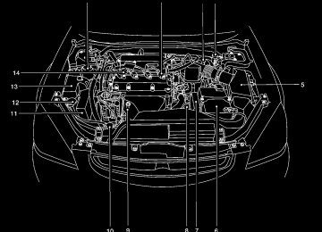
INSTRUMENT PANEL
2-2 Instruments and controls
1.
Headlight and turn signal switch (P. 2-18)
2. Meters and gauges (P. 2-3) 3. Windshield wiper/washer switch
4. 5.
6.
(P. 2-16) Center ventilator (P. 4-2) Audio system controls (if so equipped) (P. 4-14) Front passenger supplemental air bag (P. 1-8)
7. Glove box (P. 2-29) 8.
Heater and air conditioner (manual) (P. 4-3) Hazard warning flasher switch (P. 2-23)
9.
10. Power outlet (P. 2-26) 11. Rear window defroster switch (manual)
(P. 2-17)
12. Cruise control main/set switch (if so
equipped) (P. 5-12)
13. Driver supplemental air bag (P. 1-8) 14. Steering wheel switch for audio control
(if so equipped) (P. 4-29)
15. Tilt/telescopic steering wheel controls
(P. 3-14)
16. Traction control system (TCS) off switch (if so equipped) (P. 2-25)
WIC0605
Z REVIEW COPY:—2004 Altima (l30) Owners Manual (owners)—USA English (nna) 10/13/03—tbrooks X
METERS AND GAUGES
Instrument brightness control (P. 2-21) 17. 18. Outside mirror remote control (P. 3-17) 19. Front defroster switch (automatic)
(P. 4-10)
20. Heater and air conditioner (automatic)
(P. 4-10)
21. Rear window defroster switch (auto-
matic) (P. 2-17)
Tachometer
1. 2. Warning/indicator lights 3. 4.
Speedometer Automatic transmission position indica- tor lights (if so equipped) Engine coolant temperature gauge
5.
Fuel gauge
6. 7. Odometer/trip odometer
LIC0606
Instruments and controls 2-3
Z REVIEW COPY:—2004 Altima (l30) Owners Manual (owners)—USA English (nna) 10/13/03—tbrooks X
Odometer/Twin trip odometer (if so equipped) The odometer/twin trip odometer (if so equipped) is displayed when the ignition key is in the ON position. The odometer records the total distance the ve- hicle has been driven. The twin trip odometer (if so equipped) records the distance of individual trips.
WIC0600
Speedometer
1. 2. Odometer/twin trip display 3. Change button SPEEDOMETER AND ODOMETER Speedometer The speedometer indicates vehicle speed in miles per hour (MPH) and kilometers per hour (km/h).
2-4 Instruments and controls
WIC0601
! Trip
Changing the display: Pushing the change button changes the display as follows: ! Outside temperature Trip ! Distance to Empty ! Average economy ! Average speed ! Elapsed time ! Trip Resetting the trip odometer: Pushing the change button for more than 1 sec- ond resets the trip odometer to zero.
Z REVIEW COPY:—2004 Altima (l30) Owners Manual (owners)—USA English (nna) 10/10/03—tbrooks X
TRIP COMPUTER (if so equipped) The display of the trip computer is situated in the speedometer display. When the ignition is turned to ON, the display scrolls all the modes of the trip computer and then shows the mode chosen be- fore the ignition switch is turned OFF. If the battery terminal is disconnected, push the trip computer mode switch more than 1 second to activate the computer.
before the warning occurred. The ICY indicator will continue blinking as long as the temperature remains below 39(cid:176)F (4(cid:176)C).
The ambient temperature sensor is located in front of the radiator. The sensor may be affected by road or engine heat, wind directions and other driving conditions. The display may differ from the actual ambient temperature or the temperature displayed on various signs or billboards. Distance to empty (dte(cid:151)mile or km) The distance to empty (dte) mode provides you with an estimation of the distance that can be driven before refueling. The dte is constantly be- ing calculated, based on the amount of fuel in the fuel tank and the actual fuel consumption.
The display is updated every 30 seconds.
The dte mode includes a low range warning feature: when the fuel level is low, the dte mode is automatically selected and the digits blink in or- der to draw the driver(cid:146)s attention. Press the mode switch if you wish to return to the mode that was selected before the warning occurred. The dte mark (dte) will remain blinking until the vehicle is refueled.
When the fuel display will change to (----).
level drops even lower, the dte
Instruments and controls 2-5
WIC0267
When the ignition switch is turned to ON, modes of the trip computer can be selected by pushing the trip mode switch on the steering wheel switch for audio controls or by the trip computer change button. The following modes can be selected: Outside air temperature (ICY-(cid:176)F or (cid:176)C) The outside air temperature is displayed in (cid:176)F or (cid:176)C. The outside air temperature mode includes a low temperature warning feature: below 37(cid:176)F (3(cid:176)C), the outside air temperature mode is automatically selected and ICY will illuminate in order to draw the driver(cid:146)s attention. Press the mode switch if you wish to return to the mode that was selectedZ REVIEW COPY:—2004 Altima (l30) Owners Manual (owners)—USA English (nna) 10/10/03—tbrooks X
Journey time The journey time mode shows the time since the last reset. The displayed time can be reset by pressing the mode switch for more than approxi- mately 1 second.
NOTE: If a low temperature warning and low range warning occur simultaneously, other dis- play modes switch automatically to the outside temperature display. When the mode switch is pushed, the dis- play switches to the mode chosen before the warning display, and the outside air temperature indicator marked ICY will blink.
NOTE: c If the amount of fuel added while the ignition switch is OFF is small, the dis- play just before the ignition switch is turned OFF may continue to be dis- played.
c When driving uphill or rounding curves, the fuel in the tank shifts, which may momentarily change the display. Average fuel consumption (mpg or l/100km) The average fuel consumption mode shows the average fuel consumption since the last reset. Resetting is done by pressing the mode switch for more than approximately 1 second. The dis- play is updated every 30 seconds. At about the first 1/3 miles (500 m) after a reset, the display shows (----). Average speed (mph or km/h) The average speed mode shows the average vehicle speed since last reset. Resetting is done by pressing the mode switch for more than ap- proximately 1 second. The display is updated every 30 seconds. The first 30 seconds after a reset, the display shows (----).
2-6 Instruments and controls
Type A
WIC0268
TACHOMETER The tachometer indicates engine speed in revo- lutions per minute (r/min). Do not rev engine into the red zone s1 .
CAUTION
When engine speed approaches the red zone, shift to a higher gear. Operating the engine in the red zone may cause serious engine damage.
Z REVIEW COPY:—2004 Altima (l30) Owners Manual (owners)—USA English (nna) 10/10/03—tbrooks X
CAUTION
If the gauge indicates engine coolant tem- perature over the normal range, stop the vehicle as soon as safely possible. If the engine is overheated, continued opera- tion of the vehicle may seriously damage the engine. See (cid:147)If your vehicle over- heats(cid:148) in the (cid:147)In case of emergency(cid:148) sec- tion for immediate action required.
WIC0269
Type B
WIC0607
ENGINE COOLANT TEMPERATURE GAUGE The gauge indicates the engine coolant tempera- ture. The engine coolant temperature is within the normal range s1 when the gauge needle points within the zone shown in the illustration.The engine coolant temperature varies with the outside air temperature and driving conditions.
Instruments and controls 2-7
Z REVIEW COPY:—2004 Altima (l30) Owners Manual (owners)—USA English (nna) 10/10/03—tbrooks X
The located on the driver(cid:146)s side of the vehicle.
indicates that the fuel filler lid is
CAUTION
c If
the vehicle runs out of
fuel, malfunction indicator lamp the (MIL) may come on. Refuel as soon as possible. After a few driving trips, the lamp should turn off. If the lamp remains on after a few driving trips, have the vehicle inspected by a NISSAN dealer.
c For additional information, see (cid:147)Mal- function indicator lamp (MIL)(cid:148) later in this section.
WIC0608
FUEL GAUGE The gauge indicates the approximate fuel level in the tank.
The gauge may move slightly during braking, turning, acceleration, or going up or down hills.
The gauge needle returns to E (Empty) after the ignition key is turned to OFF.
The low fuel warning light comes on when the amount of fuel in the tank is getting low. Refill the fuel tank before the gauge regis- ters E (Empty).
2-8 Instruments and controls
Z REVIEW COPY:—2004 Altima (l30) Owners Manual (owners)—USA English (nna) 10/10/03—tbrooks X
WARNING/INDICATOR LIGHTS AND AUDIBLE REMINDERS
or
or
Anti-lock brake warning light (if so equipped)
Low windshield washer fluid warning light
Brake warning light
Seat belt warning light and chime
Cruise SET switch indicator light (if so equipped)
High beam indicator light (Blue)
Charge warning light
Supplemental air bag warning light
Malfunction indicator lamp (MIL)
Door open warning light
Trunk lid open warning light
Slip indicator light (if so equipped)
Engine oil pressure warning light
Low fuel warning light
Automatic transmission position indicator light (A/T models)
Traction control system off indicator light (if so equipped)
CRUISE main switch indicator light (if so equipped)
Turn signal/hazard indicator lights
CHECKING BULBS With all doors closed, apply the parking brake and turn the ignition key to the ON position without starting the engine. The following lights will come on:
If any light fails to come on, it may indicate a burned-out bulb or an open circuit in the electrical system. Have the system repaired promptly. WARNING LIGHTS
or
or
The following lights come on briefly and then go off:
or
Anti-lock brake warning light (if so equipped)
If the light comes on while the engine is running, it may indicate the anti-lock brake system is not functioning properly. Have the system checked by a NISSAN dealer.
Turn off the engine, and start it again by slowly turning the ignition key (quickly do- ing so may cause the ABS light to stay on when there is nothing wrong). If the light stays on, have the system checked by a NISSAN dealer.
If an abnormality occurs in the system, the anti- lock function ceases, but the regular braking system continues to operate. If the light comes on while you are driving, contact a NISSAN dealer for repair.
Instruments and controls 2-9
Z REVIEW COPY:—2004 Altima (l30) Owners Manual (owners)—USA English (nna) 10/10/03—tbrooks X
or
Brake warning light
This light functions for both the parking brake and the foot brake systems.
When the ignition key is in the ON position, the light comes on when the parking brake is applied, and also warns of a low brake fluid level. If the light comes on while the engine is running with the parking brake not applied, stop the vehicle and perform the following:
1. Check the brake fluid level. Add brake fluid as necessary. See (cid:147)Brake and clutch fluid(cid:148) in the (cid:147)Maintenance and do-it-yourself(cid:148) sec- tion of this manual.
2.
If the brake fluid level is correct, have the brake system checked by a NISSAN dealer.
WARNING
c Your brake system may not be working properly if the warning light is on. Driv- ing could be dangerous. If you judge it to be safe, drive carefully to the nearest service station for repairs. Otherwise, have your vehicle towed because driv- ing it could be dangerous.
2-10 Instruments and controls
c Pressing the brake pedal with the en- gine stopped and/or a low brake fluid level may increase your stopping dis- tance and braking will require greater pedal effort as well as pedal travel.
c If the brake fluid level
is below the MINIMUM or MIN mark on the brake fluid reservoir, do not drive until the brake system has been checked at a NISSAN dealer.
Charge warning light
If this light comes on while the engine is running, it may indicate the charging system is not func- tioning properly. Turn the engine off and check the generator belt. If the belt is loose, broken, missing, or if the light remains on, see a NISSAN dealer immediately.
CAUTION
Do not continue driving if the generator belt is loose, broken or missing.
Door open warning light
This light comes on when any of the doors are not closed securely while the ignition key is in the ON position.
Engine oil pressure warning light
This light warns of low engine oil pressure. If the light flickers or comes on during normal driving, pull off the road in a safe area, stop the engine immediately and call a NISSAN dealer or other authorized repair shop. The engine oil pressure warning light is not designed to indicate a low oil level. Use the dipstick to check the oil level. See (cid:147)Engine oil(cid:148) in the (cid:147)Maintenance and do-it-yourself(cid:148) section of this manual.
CAUTION
Running the engine with the engine oil pressure warning light on could cause se- rious damage to the engine almost imme- diately. Such damage is not covered by warranty. Turn off the engine as soon as it is safe to do so.
Low fuel warning light
This light comes on when the fuel level in the fuel tank is getting low. Refuel as soon as it is conve- nient, preferably before the fuel gauge reaches E (Empty). There will be a small reserve of fuel in the tank when the fuel gauge needle reaches E (Empty).
Z REVIEW COPY:—2004 Altima (l30) Owners Manual (owners)—USA English (nna) 10/10/03—tbrooks X
Low windshield washer fluid warning light
This light comes on when the windshield washer fluid is at a low level. Add windshield washer fluid as necessary. See the (cid:147)Maintenance and do-it- yourself(cid:148) section of this manual.
Seat belt warning light and chime
The light and chime remind you to fasten your seat belts. The light illuminates whenever the ignition key is turned to the ON or START position and remains illuminated until the driver(cid:146)s seat belt is fastened. At the same time, the chime sounds for about 7 seconds unless the driver(cid:146)s seat belt is securely fastened. Refer to (cid:147)Seat belts(cid:148) in the (cid:147)Safety(cid:151)Seats, seat belts and supplemental air bags(cid:148) section for pre- cautions on seat belt usage.
Supplemental air bag warning light
When the ignition key is in the ON or START position, the supplemental air bag warning light illuminates for about 7 seconds and then turns off. This means the system is operational. If any of the supplemental front air bag, supplemental side air
the following conditions occur,
bag (if so equipped), curtain side-impact air bags (if so equipped), and pre-tensioner seat belt sys- tems need servicing and your vehicle must be taken to a NISSAN dealer: c The supplemental air bag warning light re-
mains on after approximately 7 seconds.
c The supplemental air bag warning light
flashes intermittently.
c The supplemental air bag warning light does
not come on at all.
Unless checked and repaired, the supplemental restraint system (air bag system) and/or the pre- tensioner seat belts may not function properly. For additional details see (cid:147)Supplemental restraint system(cid:148) in the (cid:147)Seats, restraints and supplemen- tal air bag systems(cid:148) section of this manual.
WARNING
If the supplemental air bag warning light is on, it could mean that the supplemental front air bag, supplemental side air bag, curtain side-impact air bag systems (if so equipped) and/or pre-tensioner seat belt systems will not operate in an accident.
Trunk lid open warning light
This light comes on when the trunk lid is not securely closed while the ignition key is in the ON position. INDICATOR LIGHTS
Automatic transmission posi- tion indicator light (A/T mod- els)
When the ignition key is turned to the ON posi- tion, this indicator light shows the automatic transmission selector lever position. See (cid:147)Driving the vehicle(cid:148) in the (cid:147)Starting and driving(cid:148) section of this manual.
Cruise main switch indicator light (if so equipped)
The light comes on when the cruise control main switch is pushed. The light goes out when the main switch is pushed again. When the cruise main switch indicator light comes on, the cruise control system is operational.
Cruise set switch indicator light (if so equipped)
The light comes on while the vehicle speed is controlled by the cruise control system. If the light blinks while the engine is running, it may indicate Instruments and controls 2-11
Z REVIEW COPY:—2004 Altima (l30) Owners Manual (owners)—USA English (nna) 10/10/03—tbrooks X
the cruise control system is not functioning prop- erly. Have the system checked by a NISSAN dealer.
High beam indicator light (Blue)
This blue light comes on when the headlight high beams are on and goes out when the low beams are selected.
The high beam indicator light also comes on when the passing signal is activated.
Malfunction indicator lamp (MIL)
If this indicator lamp comes on steady or blinks while the engine is running, it may indicate a potential emission control malfunction.
The malfunction indicator lamp may also come on steady if the fuel filler cap is loose or missing, or if the vehicle runs out of fuel. Check to make sure the fuel filler cap is installed and closed tightly, and that the vehicle has at least 3 gallons of fuel in the fuel tank.
After a few driving trips, the lamp should turn off if no other potential emission control system malfunction exists.
2-12 Instruments and controls
Operation
The malfunction indicator lamp will come on in one of two ways: c Malfunction indicator lamp on steady (cid:151) An emission control system malfunction has been detected. Check the fuel filler cap. If the fuel filler cap is loose or missing, tighten or install the cap and continue to drive the lamp should turn off after vehicle. The a few driving trips. If the lamp does not turn off after a few driving trips, have the vehicle inspected by a NISSAN dealer. You do not need to have your vehicle towed to the dealer.
c Malfunction indicator lamp blinking (cid:151) An engine misfire has been detected which may damage the emission control system. To re- duce or avoid emission control system dam- age: (cid:150) do not drive at speeds above 45 MPH
(72 km/h).
(cid:150) avoid hard acceleration or deceleration. (cid:150) avoid steep uphill grades. (cid:150) if possible, reduce the amount of cargo
being hauled or towed.
The malfunction indicator lamp may stop blinking and come on steady. Have the vehicle inspected by
a NISSAN dealer. You do not need to have your vehicle towed to the dealer.
CAUTION
Continued vehicle operation without hav- ing the emission control system checked and repaired as necessary could lead to poor driveability, reduced fuel economy, and possible damage to the emission con- trol system.
Slip indicator light (if so equipped)
This indicator light will blink when the traction control system is limiting wheel spin. Slippery road conditions may exist if the slip indicator blinks on. If this happens, adjust your driving accordingly.
The slip indicator light also comes on when you turn the ignition key to the ON position. The light will turn off after about 2 seconds if the system is operational. If the light does not come on or go off, have the traction control system checked by a NISSAN dealer.
The system operates in all transmission shift lever positions, but the system can upshift the trans- mission only as high as the indicated shift lever position.
Z REVIEW COPY:—2004 Altima (l30) Owners Manual (owners)—USA English (nna) 10/10/03—tbrooks X
AUDIBLE REMINDERS Brake pad wear warning The disc brake pads have audible wear warnings. When a brake pad requires replacement, it makes a high pitched scraping sound when the vehicle is in motion, whether or not the brake pedal is depressed. Have the brakes checked as soon as possible if the warning sound is heard. Key reminder chime A chime sounds if the driver(cid:146)s door is opened while the key is left in the ignition switch. Remove the key and take it with you when leaving the vehicle. Light reminder chime With the ignition switch in the OFF position, a chime sounds when the driver(cid:146)s door is opened if the headlights or parking lights are on. Turn the headlight control switch off before leav- ing the vehicle.
Traction control system off indicator light (if so equipped) This indicator light comes on when the traction control off switch is pushed to OFF. This indi- cates the traction control system is not operating.
Push the traction control off switch again or re- start the engine and the system will operate nor- mally. See (cid:147)Traction control system (TCS)(cid:148) in the (cid:147)Starting and driving(cid:148) section of this manual.
The traction control light also comes on when you turn the ignition key to the ON position. The light will turn off after about 2 seconds if the traction control system (TCS) is operational. If the light stays on or comes on along with the SLIP indica- tor light while you are driving, have the traction control system checked by a NISSAN dealer.
While the traction control system is operating, you might feel slight vibration or hear the system working when starting the vehicle or accelerat- ing, but this is normal.
Turn signal/hazard indicator lights
The appropriate light flashes when the turn signal switch is activated. Both lights flash when the hazard switch is turned on.
SECURITY SYSTEMS
LIC0301
Your vehicle has two types of security systems: c Vehicle security system (if so equipped) c NISSAN Vehicle Immobilizer System(cid:151)NVIS VEHICLE SECURITY SYSTEM (if so equipped) The vehicle security system provides visual and audio alarm signals if parts of the vehicle are disturbed. How to arm the vehicle security sys- tem 1. Close all windows. (The system can be armed even if the windows are open.) Instruments and controls 2-13Z REVIEW COPY:—2004 Altima (l30) Owners Manual (owners)—USA English (nna) 10/10/03—tbrooks X
2. Remove the key from the ignition switch.
3. Close the trunk lid and all doors. Lock all doors. The doors can be locked with the key, power door is opened, locked, and then closed) or with the keyfob.
lock switch (if
the door
Keyfob operation: c Push the
button on the keyfob. All doors lock. The hazard lights flash twice and the horn beeps once to indicate all doors are locked.
c When the
button is pushed with all doors locked, the hazard lights flash twice and the horn beeps once as a re- minder that the doors are already locked.
The horn may or may not beep. Refer to (cid:147)Silencing the horn beep feature(cid:148) later in this section.
2-14 Instruments and controls
4. Confirm that the SECURITY indicator light comes on. The SECURITY light stays on for about 30 seconds. The vehicle security sys- tem is now pre-armed. After about 30 sec- onds the vehicle security system automati- cally shifts into the armed phase. The SECURITY light begins to flash once every 3
seconds. If, during the 30-second pre-arm time period, the door is unlocked by the key or the keyfob, or the ignition key is turned to ACC or ON, the system will not arm.c If the key is turned slowly when locking the door, the system may not arm. Fur- thermore, if the key is turned beyond the vertical position toward the unlock position to remove the key, the system may be disarmed when the key is re- moved. If the indicator light fails to glow for 30 seconds, unlock the door once and lock it again.
c Even when the driver and/or passen- gers are in the vehicle, the system will arm with all doors and trunk lid closed and locked with the ignition key in the OFF position.
Vehicle security system activation The vehicle security system will give the following alarm: c The headlights blink and the horn sounds
intermittently.
c The alarm automatically turns off after ap- proximately 45 seconds. However, the alarm reactivates if the vehicle is tampered with again. The alarm can be shut off by unlocking a door or trunk lid with the key, or by pressing the
button on the keyfob.
The alarm is activated by: c opening the door or trunk lid without using the key or keyfob (even if the door is un- locked by releasing the door inside lock switch).
How to stop an activated alarm The alarm stops only by unlocking a door or the trunk lid with the key, or by pressing the button on the keyfob.
Z REVIEW COPY:—2004 Altima (l30) Owners Manual (owners)—USA English (nna) 10/10/03—tbrooks X
WIC0271
Silencing the horn beep feature If desired, the horn beep feature can be deacti- vated using the keyfob. To deactivate: Press and hold both the and 2 seconds.
buttons at the same time for at least
The hazard lights will quickly flash 3 times to confirm that the horn beep feature has been deactivated. To activate: Press and hold both the and 2 seconds once more.
buttons at the same time for at least
The hazard lights will quickly flash once and the horn will sound once to confirm that the horn beep feature has been reactivated.
Deactivating the horn feature does not silence the horn if the alarm is triggered. If the system does not operate as described above, have it checked by a NISSAN dealer. NISSAN VEHICLE IMMOBILIZER SYSTEM (NVIS) The NISSAN Vehicle Immobilizer System (NVIS) will not allow the engine to start without the use of a registered NVIS key. If the engine fails to start using a registered NVIS key (for example, when interference is caused by another NVIS key, an automated toll road device or automatic payment device on the key ring), restart the engine using the following proce- dures: 1. Leave the ignition switch in the ON position
for approximately 5 seconds.
2. Turn the ignition switch to the OFF or LOCK position, and wait approximately 5 seconds.
3. Repeat steps 1 and 2. 4. Restart the engine while holding the device (which may have caused the interference) separate from the registered NVIS key.
If the no start condition re-occurs, NISSAN rec- ommends placing the registered NVIS key on a separate key ring to avoid interference from other devices. Statement related to Section 15 of FCC Rules for NISSAN Vehicle Immobilizer Sys- tem (CONT ASSY (cid:151) IMMOBILIZER, ANT ASSY (cid:151) IMMOBILIZER) This device complies with part 15 of the FCC Rules and RSS-210 of Industry Canada. Operation is subject to the follow- ing two conditions; (1) This device may not cause harmful in- terference, and (2) this device must accept any interference received, including inter- ference that may cause undesired opera- tion of the device. CHANGES OR MODIFICATIONS NOT EX- PRESSLY APPROVED BY THE MANUFAC- TURER FOR COMPLIANCE COULD VOID THE USER(cid:146)S AUTHORITY TO OPERATE THE EQUIPMENT.
Instruments and controls 2-15
Z REVIEW COPY:—2004 Altima (l30) Owners Manual (owners)—USA English (nna) 10/10/03—tbrooks X
WINDSHIELD WIPER AND WASHER SWITCH
If the light still remains on and/or the en- gine will not start, see a NISSAN dealer for NVIS service as soon as possible. Please bring all NVIS keys that you have when visiting your NISSAN dealer for service.
WIC0270
Security indicator light (NISSAN Ve- hicle Immobilizer System) The security indicator light s1 is located on the instrument panel near the windshield. The security indicator light blinks every 3 sec- onds whenever the ignition switch is in the LOCK, OFF or ACC position. This function indi- cates the NISSAN Vehicle Immobilizer System (NVIS) is operational. If the NVIS is malfunctioning, the light will remain on while the ignition key is in the ON position.
2-16 Instruments and controls
WIC0613
SWITCH OPERATION The windshield wiper and washer switch oper- ates when the ignition key is in the ON position.
Push the lever down to operate the wiper at the following speed: s1
Intermittent (cid:151) intermittent operation can be adjusted by turning the knob toward sA (Slower) or sB (Faster). s2
Low (cid:151) continuous low speed operation s3 High (cid:151) continuous high speed operation Push the lever up s4 to have one sweep opera- tion of the wiper.Z REVIEW COPY:—2004 Altima (l30) Owners Manual (owners)—USA English (nna) 10/10/03—tbrooks X
Pull the lever toward you s5
to operate the washer. The wiper will also operate several times.WARNING
In freezing temperatures the washer solu- tion may freeze on the windshield and obscure your vision which may lead to an accident. Warm the windshield with the defroster before you wash the windshield.
CAUTION
c Do not operate the washer continu-
ously for more than 30 seconds.
c Do not operate the washer if the reser-
voir tank is empty.
c Do not fill the window washer reservoir tank with washer fluid concentrates at full strength. Some methyl alcohol based washer fluid concentrates may perma- nently stain the grille if spilled while fill- ing the window washer reservoir tank.
c Pre-mix washer fluid concentrates with water to the manufacturer(cid:146)s recom- mended levels before pouring the fluid into the window washer reservoir tank. Do not use the window washer reservoir tank to mix the washer fluid concen- trate and water.
REAR WINDOW AND OUTSIDE MIRROR (if so equipped) DEFROSTER SWITCH
WIC0272
LIC0317
Type A
To defrost the rear window glass and outside mirrors (if so equipped), start the engine and push the rear window defroster switch on. The rear window defroster light on the switch comes on. Push the switch again to turn the defroster off. The rear window defroster automatically turns off after approximately 15 minutes.
indicator
Type B
CAUTION
When cleaning the inner side of the rear window, be careful not to scratch or dam- age the rear window defroster.
NOTE: The top few rows of wires on the rear win- dow are not part of the rear window de- froster system. These wires make up the antenna for the audio system.
Instruments and controls 2-17
Z REVIEW COPY:—2004 Altima (l30) Owners Manual (owners)—USA English (nna) 10/10/03—tbrooks X
(for example, when the vehicle stops at a traffic signal). Even when the daytime running lights are active (Canada only), the xenon headlights do not turn on. This way the life of the xenon head- lights is not reduced.
c If the xenon headlight bulb is close to burning out, the brightness will drasti- cally decrease, the light will start blink- ing, or the color of the light will be- come reddish. If one or more of the above signs appear, contact a NISSAN dealer.
HEADLIGHT AND TURN SIGNAL SWITCH
XENON HEADLIGHTS (if so equipped)
WARNING
cHIGH VOLTAGE
c When xenon headlights are on, they produce a high voltage. To prevent an electric shock, never attempt to modify or disassemble. Always have your xe- non headlights replaced at a NISSAN dealer.
c Xenon headlights provide considerably more light than conventional head- lights. If they are not correctly aimed, they might temporarily blind an oncom- ing driver or the driver ahead of you and cause a serious accident. If headlights are not aimed correctly, immediately take your vehicle to a NISSAN dealer and have the headlights adjusted correctly.
When the xenon headlight is initially turned on, its brightness or color varies slightly. However, the color and brightness will soon stabilize. c The life of xenon headlights will be shortened by frequent on-off opera- tion. It is generally desirable not to turn off the headlights for short intervals
Type C
LIC0637
2-18 Instruments and controls
Z REVIEW COPY:—2004 Altima (l30) Owners Manual (owners)—USA English (nna) 10/10/03—tbrooks X
Type A
Type B
Type C
WIC0312
WIC0313
WIC0314
HEADLIGHT CONTROL SWITCH Lighting s1 When turning the switch to the
posi- tion, the front parking, tail, license plate and instrument panel lights come on. s2 When turning the switch to the
posi- tion, the headlights come on and all the other lights remain on.
Instruments and controls 2-19
Z REVIEW COPY:—2004 Altima (l30) Owners Manual (owners)—USA English (nna) 10/10/03—tbrooks X
WIC0597
Autolight system (if so equipped) The autolight system allows the headlights to be set so they turn on and off automatically. The autolight system can: c Turn on the headlights automatically when it
is dark. See your NISSAN dealer to have the autolight activation sensitivity setting adjusted.
c Turn off the headlights when it is light. c Keep the headlights on for up to 180 sec- onds after you turn the key to OFF, open and
2-20 Instruments and controls
close the driver(cid:146)s or passenger(cid:146)s door, and then close all doors. The default time delay for autolight shutoff is 45 seconds. See your NISSAN dealer to have the time delay setting adjusted.
If the ignition switch is turned OFF and one of the doors is opened, the headlights remain ON for 5
minutes. To set the autolight system: 1. Make sure the headlight switch is in theAUTO position s1 .
2. Turn the ignition key to ON. 3. The autolight system automatically turns the
headlights on and off.
, or
position.
To turn the autolight system off, turn the switch to the OFF, Be sure you do not put anything on top of the autolight sensor located in the top driver side of the instrument panel. The autolight sensor controls the autolight; if it is covered, the autolight sensor reacts as if it is dark out and the headlights will illumi- nate. If this occurs while parked with the engine off and the key in the ON position, your vehicle(cid:146)s battery could become dis- charged.
LIC0318
Headlight beam select s1 To select the high beam function, push the lever forward. The high beam lights come on and the
light illuminates.
s2 Pull the lever back to select the low beam. s3 Pulling and releasing the lever flashes the
headlight high beams on and off.
Battery saver system If the ignition switch is turned OFF while the headlight switch is in the posi- tion, the headlights will turn off after 5 minutes.
or
Z REVIEW COPY:—2004 Altima (l30) Owners Manual (owners)—USA English (nna) 10/10/03—tbrooks X
CAUTION
WARNING
c Be sure to turn the light switch to the OFF position when you leave the ve- hicle for extended periods of time, oth- erwise the battery will go dead.
c Never leave the light switch on when the engine is not running for extended periods of time even if the headlights turn off automatically.
DAYTIME RUNNING LIGHT SYSTEM (Canada only) The headlights automatically illuminate at a re- duced intensity when the engine is started with the parking brake released. The daytime running lights operate with the headlight switch in the OFF position or in the position. Turn the headlight switch to the position for full illumination when driving at night.
If the parking brake is applied before the engine is started, the daytime running lights do not illumi- nate. The daytime running lights illuminate when the parking brake is released. The daytime run- ning lights will remain on until the ignition switch is turned off.
When the daytime running light system is active, tail lights on your vehicle are not on. It is necessary at dusk to turn on your headlights. Failure to do so could cause an accident injuring yourself and others.
WIC0273
INSTRUMENT BRIGHTNESS CONTROL The instrument cluster illuminates when the igni- tion switch is in ON position. The instrument brightness control operates when the the AUTO, Turn the control to adjust the brightness of instru- ment panel lights when driving at night. The instrument brightness control will not adjust the brightness when the headlights or parking lights are off.
headlight