- 2009 Nissan Altima Owners Manuals
- Nissan Altima Owners Manuals
- 2002 Nissan Altima Owners Manuals
- Nissan Altima Owners Manuals
- 1999 Nissan Altima Owners Manuals
- Nissan Altima Owners Manuals
- 2004 Nissan Altima Owners Manuals
- Nissan Altima Owners Manuals
- 2003 Nissan Altima Owners Manuals
- Nissan Altima Owners Manuals
- 1997 Nissan Altima Owners Manuals
- Nissan Altima Owners Manuals
- 2010 Nissan Altima Owners Manuals
- Nissan Altima Owners Manuals
- 1996 Nissan Altima Owners Manuals
- Nissan Altima Owners Manuals
- 2005 Nissan Altima Owners Manuals
- Nissan Altima Owners Manuals
- 1998 Nissan Altima Owners Manuals
- Nissan Altima Owners Manuals
- 2008 Nissan Altima Owners Manuals
- Nissan Altima Owners Manuals
- 2007 Nissan Altima Owners Manuals
- Nissan Altima Owners Manuals
- 2001 Nissan Altima Owners Manuals
- Nissan Altima Owners Manuals
- 2000 Nissan Altima Owners Manuals
- Nissan Altima Owners Manuals
- 2011 Nissan Altima Owners Manuals
- Nissan Altima Owners Manuals
- 2012 Nissan Altima Owners Manuals
- Nissan Altima Owners Manuals
- 2006 Nissan Altima Owners Manuals
- Nissan Altima Owners Manuals
- Download PDF Manual
-
Passing signal Pulling and releasing the lever flashes the headlight high beams on and off. Turn signal Move the lever up or down to signal the turning direction. When the turn is com- pleted, the turn signals cancel automati- cally. Lane change signal To signal a lane change, move the lever up or down to the point where the indicator light begins to flash, but the lever does not latch.
DAYTIME RUNNING LIGHT SYS- TEM (for Canada) The headlights automatically illuminate at a reduced intensity when the engine is started with the parking brake released. The day- time running lights operate with the head- light switch in the ‘‘OFF’’ position or in the ’’ position. Turn the headlight switch ‘‘ to the ‘‘ illumination when driving at night. If the parking brake is applied before the engine is started, the daytime running lights do not illuminate. The daytime running lights illuminate once the parking brake is re- leased. The daytime running lights will re- main on until the ignition switch is turned off.
’’ position for full
WARNING
When the daytime running light system is active, tail lights on your vehicle are not on. It is necessary at dusk to turn on your headlights. Failure to do so could cause an accident injuring your- self and others.
CORNERING LIGHT (If so equipped)
IC1030
The cornering light provides additional illu- mination toward the turning direction. The light on the turning direction side comes on when a turn is signaled with the headlights on.
1-13
Z X
INSTRUMENT BRIGHTNESS CONTROL
FRONT FOG LIGHT SWITCH (If so equipped)
HAZARD WARNING FLASHER SWITCH
IC1269
IC1292
IC1271
The instrument brightness control operates when the light switch is in the or
position.
Turn the control to adjust the brightness of instrument panel lights. NOTE: For vehicles with the clock located in the instrument panel, the instrument bright- ness control function has no effect on the brightness of the clock.
position.
To turn the front fog lights on, rotate the switch to the To turn them off, turn the switch to the OFF position. The low-beam headlight function must be on for the fog lights to operate. The fog lights automatically turn off whenever the high-beam headlight function is selected.
Push the switch on to warn other drivers when you must stop or park under emer- gency conditions. All turn signal lights flash.
WARNING
c When stalled or stopped on the road- way under emergency conditions, move the vehicle well off the road.
1-14
Z X
c Do not use the switch while moving on the highway unless unusual cir- cumstances force you to drive so slowly that your vehicle might be- come a hazard to other traffic.
c Turn signals do not work when the hazard warning flasher lights are on.
The flashers can be actuated with the igni- tion switch either OFF or ON. Some state laws may prohibit the use of the hazard warning flasher switch while driving.
CIGARETTE LIGHTER (ACCESSORY) AND ASH TRAY
CAUTION
The cigarette lighter socket is a power source for the cigarette lighter element only. The use of the cigarette lighter socket as a power source for any other accessory is not recommended.
WARNING
The cigarette lighter should not be used while driving in order that full attention may be given to the driving operation.
AIC0509
The cigarette lighter element is an acces- sory. A genuine NISSAN cigarette lighter or equivalent can be purchased from your lo- cal NISSAN dealer. The cigarette lighter operates when the ignition switch is in the ACC or ON position. Push the lighter in all the way. When the lighter is heated, it springs out. Return the lighter to its original position after use.
1-15
Z X
CUP HOLDER
MANUAL WINDOWS
AIC0087
To open, pull the cup holder out. To close, push the cup holder in. The cup holder and the ashtray cannot be used at the same time. Close the ashtray before using the cup holder.
WARNING
The driver should not pull out the cup holder or remove or insert cups into the cup holder while driving in order that full attention may be given to the driv- ing operation.
CAUTION
c Avoid abrupt starting and braking when the cup holder is being used to prevent spilling the drink. If the liq- uid is hot, it can scald you or your passenger.
c Use only soft cups in the cupholder. Hard objects can injure you in an accident.
The side windows can be opened or closed by turning the hand crank on each door.
AIC0648
1-16
Z X
POWER WINDOWS
WARNING
c Make sure that all passengers have their hands, etc. inside the vehicle before closing the windows. Use the window lock switch to prevent unex- pected use of the power windows.
c Do not leave children unattended in- side the vehicle. They could un- knowingly activate switches or con- trols and become trapped in a window. Unattended children could become involved in serious acci- dents.
AIC0518
AIC0517
The power windows operate only when the ignition key is in the ON position. To open a window, press down on the switch. To close a window, push up on the switch. To stop the opening or closing function at any time, simply release the switch. The driver side control panel is equipped with switches to open or close all of the windows.
AUTOMATIC POWER WINDOW SWITCH To fully open the driver side window, com- pletely press the driver side window switch down and release it; it need not be held. The window automatically opens all the way. To stop the window, push up on the switch while the window is opening.
1-17
Z X
REAR POWER WINDOWS
SUNROOF (If so equipped)
AIC0501
IC1285
AIC0522
The front passenger switch operates only the front passenger window. To open or close the window, press and hold the switch. Locking passenger windows When the power window lock switch on the driver side control panel is pushed in, only the driver side window can be opened or closed. Push it in again to cancel this func- tion.
The sunroof only operates when the ignition key is in the ON position. Sliding the sunroof To open the roof, press and hold the switch to the OPEN side. To close the roof, press and hold the switch to the CLOSE side.
1-18
Z X
Tilting the sunroof To tilt up, first close the sunroof, then push and hold the UP side of the tilt switch. To close the sunroof, push and hold the DOWN side. Sun shade Open and close the sun shade by sliding it forward or backward.
WARNING
c In an accident you could be thrown from the vehicle through an open sunroof. Always use seat belts and child restraints.
c Do not allow anyone to stand up or extend any portion of their body out of the opening while the vehicle is in motion or while the sunroof is closing.
CAUTION
c Remove water drops, snow, ice or sunroof before
sand from the opening.
c Do not place any heavy object on the
sunroof or surrounding area.
IF THE SUNROOF DOES NOT CLOSE 1. Turn the ignition key to the OFF position. in the
Be sure no objects are caught sunroof opening.
2. Remove the spotlight unit. The shaft end
of the sunroof motor will be visible.
3. Using a 5mm (0.20 in) hex wrench, turn the shaft clockwise to close the sunroof. Have the sunroof system checked and re- paired by your NISSAN dealer.
AIC0519
1-19
Z X
CLOCK — INSTRUMENT PANEL (If so equipped)
INTERIOR LIGHT
CAUTION
Leaving the interior light switch in the ON position for extended periods of time will result in a discharged battery.
AIC0500
IC1235M
The digital clock displays time when the ignition key is in the ACC or ON position. If the power supply is disconnected, the clock will not indicate the correct time. Readjust the time. Adjusting the time Push the H button to adjust the hour. Push the M button to adjust the minute. NOTE: The clock displays 12-hour time with no AM/PM indications.
The interior light operates regardless of ignition key position. The interior light has a three-position switch. c When the switch is in the OFF position, the interior light does not illuminate, re- gardless of door position.
c When the switch is in the center j illuminates
the interior
position, when a door is opened.
light
c When the switch is in the ON position, the interior light illuminates, whether any door is open or closed.
1-20
Z X
SPOTLIGHT (If so equipped)
TRUNK LIGHT
The light illuminates when the trunk lid is opened. When the trunk lid is closed, the light goes off.
IC1019
IC1278
1-21
Z X
Z X
2 Pre-driving checks and adjustments
Key .........................................................................2-2
Door locks ..............................................................2-2
Manual door lock....................................................2-2
Power door lock .....................................................2-3
Child safety rear door lock.....................................2-4
Multi-remote control system (if so equipped).........2-4
Battery replacement ...............................................2-6
Hood release..........................................................2-8
Glove box ...............................................................2-8
Trunk lid lock operation..........................................2-9
Opener cancel lever for trunk lid..........................2-10
Fuel filler lid lock operation ..................................2-10
Fuel filler cap........................................................2-11
Front seats ...........................................................2-12
Seat adjustment ...................................................2-12
Head restraints.....................................................2-14
Rear seat..............................................................2-15
Supplemental restraint system (air bag system).................................................................2-16Supplemental air bag system...............................2-19
Warning labels......................................................2-21
Supplemental air bag warning light......................2-21
Seat belts .............................................................2-23
Precautions on seat belt usage ...........................2-23
Child safety...........................................................2-25
3-point type with retractor ....................................2-26
2-point type without retractor (center position of rear seat)..........................................................2-28
Seat belt extenders ..............................................2-30
Seat belt maintenance .........................................2-30
Child restraints for infants and small children......2-30
Top strap child restraint .......................................2-34
Tilting steering wheel ...........................................2-37
Outside mirror remote control ..............................2-37
Outside mirrors.....................................................2-37
Inside mirror .........................................................2-38
Vanity mirror.........................................................2-38Z X
KEY
DOOR LOCKS
APD0512
PD1305
APD0520
MANUAL DOOR LOCK To lock the front doors from the outside, turn the key toward the front of the vehicle. To unlock, turn it toward the rear.
To lock a door from inside the vehicle, press the lock knob (located above the door handle) until it is flush with the door panel. To unlock, pull the lock knob to its outer position.
The master key can be used for all of the locks. A key number plate is supplied with your key. Record the key number on the key number plate and keep it in a safe place (such as your wallet), NOT IN THE CAR. NISSAN does not record key numbers so it is very important to keep track of your key number plate. A key number is only necessary when you have lost all keys and do not have one to duplicate from. If you still have a key, this key can be duplicated by your NISSAN dealer or a locksmith shop.
2-2
Z X
APD0528
APD0521
APD0527
POWER DOOR LOCK The power door lock system allows you to lock or unlock all doors simultaneously. Turning the front door key to the front of the vehicle locks all doors. Turning the front door key one time to the rear of the vehicle unlocks the correspond- ing door. From that position, returning the key to Neutral (where the key can only be removed and inserted) and turning it to the rear again within 5 seconds unlocks all doors.
To lock from the outside without a key, push the door lock button (driver side only) or the door lock knob (driver or passenger side), then close the door. When locking the door this way, be certain not to leave the key inside the vehicle. All doors automatically unlock with the key in the ignition.
WARNING
c Always have the doors locked while driving. Along with the use of seat belts, this provides greater safety in the event of an accident by helping to prevent persons from being thrown from the vehicle. This also helps keep children and others from unintentionally opening the doors, and will help keep out intruders.
c Before opening any door, always look for and avoid oncoming traffic.
2-3
Z X
c Do not leave children unattended in- side the vehicle. They could un- knowingly activate switches or con- trols. Unattended children could become involved in serious acci- dents.
PD1101
CHILD SAFETY REAR DOOR LOCK Child safety locks help prevent rear doors from being opened accidentally, especially when small children are in the vehicle. The child safety lock levers are located on the edge of the rear doors. When the lever is in the lock position, the door can be opened only from the outside.
2-4
MULTI-REMOTE CONTROL SYSTEM (if so equipped) It is possible to lock/unlock all doors, turn the interior light on and activate the panic alarm by using the remote controller from outside the vehicle. Be sure to remove the key from the vehicle before locking the doors and leaving it. The remote controller can operate at a distance of approximately 49 ft (15 m) from the vehicle. (The effective distance depends on the conditions around the vehicle.) As many as four remote controllers can be used with one vehicle. For information con- cerning the purchase and use of additional remote controllers, contact your NISSAN dealer.
CAUTION
Listed below are conditions or occur- rences which will damage the remote controller: c Do not allow the remote controller to
become wet.
Z X
c Do not drop the remote controller. c Do not strike the remote controller
sharply against another object.
c Do not place the remote controller for an extended period in an area where temperatures exceed 140°F (60°C).
Locking doors 1. Remove the ignition key. 2. Close all of the doors. 3. Push the controller.
button on the multi-remote
4. All of the doors lock. 5. The hazard indicators flash twice. c When the
doors flashes twice as a reminder that doors are already locked.
button is pushed with all the hazard indicator the
locked,
Unlocking doors 1. Push the
button on the multi- remote controller. Only the driver side door unlocks.
2. Push the
button on the multi- 2-5
APD0641
remote controller again within five sec- onds. The passenger doors unlock.
3. The interior light comes on and stays on for 30 seconds when the light switch is in the O position.
Z X
BATTERY REPLACEMENT
The interior light can be turned off without waiting 30 seconds by inserting the key into the ignition or locking the doors with the multi-remote controller or pushing the interior light button to OFF. Using the panic alarm If you are near your vehicle and feel threat- ened, you may activate the alarm to call attention as follows: 1. Push the
button on the remote con-
troller for longer than 1.5 seconds.
2. The theft warning alarm and headlights
will stay on for 30 seconds.
3. The panic alarm stops when: c it has run for 30 seconds, or c the c the
or the button is pressed, or button is pushed for longer than 1.5 seconds on the multi-remote control- ler.
Replace the battery in the multi-remote con- troller as follows: 1. Open the lid using a coin. 2. Replace the battery with a new one.
Insert the battery as illustrated above.
2-6
APD0535
Recommended battery: Sanyo CR2025
or equivalent.3. Close the lid securely. 4. Press the
button, then the
button two or three times to check the multi- remote controller operation.
Z X
ceived including interference that may cause undesired operation of the device.
If the batteries are removed for any rea- son other than replacement, perform step 4 above. c An improperly disposed battery can hurt the environment. Always confirm local regulations for battery disposal. c The multi-remote controller is water- resistant; however, if it does get wet, immediately wipe completely dry.
c The operational range of the multi- remote controller extends to approxi- mately 49 ft (15 m) from the vehicle. This range may vary with conditions.
FCC Notice: Changes or modifications not expressly approved by the manufacturer for com- pliance could void the user’s authority to operate the equipment. This device complies with part 15 of the FCC Rules and RSS-210 of Industry Canada. Operation is subject to the following two conditions: (1) This device may not cause harmful interference, and (2) this device must accept any interference re-
2-7
Z X
HOOD RELEASE
GLOVE BOX
APD0505
PD1310
1. Pull
the hood lock release handle s1
located below the instrument panel; the hood springs up slightly.2. Push the lever s2 at the front of the hood with your fingertips and raise the hood. 3. Insert the support rod s3 into the slot on
the underside of the hood.
4. When closing the hood, return the sup- port then slowly close the hood and make sure it locks into place.
rod to its original position,
WARNING
c Make sure the hood is completely closed and latched before driving. Failure to do so could cause the hood to fly open and result in an accident.
c If you see steam or smoke coming to
from the engine compartment, avoid injury do not open the hood.
2-8
Use the master key to lock or unlock the glove box. The glove box opens by pulling the handle. To illuminate the interior of the glove box, the headlight switch must be turned to the
or
position (If so equipped).
CAUTION
Keep glove box lid closed while driving to help prevent injury in an accident or a sudden stop.
Z X
TRUNK LID LOCK OPERATION
Opener lever operation The trunk lid opener lever is located on the outside of the driver’s seat. To open the trunk lid, pull up the opener lever. To close, lower and push the trunk lid down securely.
APD0506
PD1312
Key operation To open the trunk lid, turn the key clock- wise. To close, lower and push the trunk lid down securely.
WARNING
Do not drive with the trunk lid open. This could allow dangerous exhaust gases to be drawn into the vehicle. See ‘‘Exhaust Gas’’ in the ‘‘Starting and Driving’’ Section.
2-9
Z X
FUEL FILLER LID LOCK OPERATION
APD0111
OPENER CANCEL LEVER FOR TRUNK LID When this lever is in the cancel position, the trunk lid cannot be opened with the trunk lid opener lever. It can be opened only with the key.
Opener lever operation The fuel filler lid opener lever is located on the outside of the driver’s seat. To open the fuel filler lid, push the opener lever down. To lock, close the fuel filler lid securely.
APD0525
2-10
Z X
WARNING
c Gasoline is extremely flammable and highly explosive under certain condi- tions. You could be burned or seri- ously injured if it is misused or mis- handled. Always stop the engine and do not smoke or allow open flames or sparks vehicle when refueling.
near
the
PD1013
FUEL FILLER CAP The fuel filler cap is a screw-on ratcheting type. Tighten the cap clockwise until ratch- eting clicks are heard.
c Fuel may be under pressure. Turn the cap one-half turn, and wait for any ‘‘hissing’’ sound to stop to pre- vent fuel from spraying out and pos- sible personal injury. Then remove the cap.
c Use only a genuine NISSAN fuel filler cap as a replacement. It has a built-in safety valve needed for proper op- eration of the fuel system and emis- sion control system. An incorrect cap can result in a serious malfunc- tion and possible injury.
CAUTION
If fuel is spilled on the car body, flush it away with water to avoid paint damage.
2-11
Put the fuel filler cap on the cap holder while refueling.
PD1014
Z X
FRONT SEATS
SEAT ADJUSTMENT
WARNING
c Do not adjust the driver’s seat while driving. The seat may move sud- denly and could cause loss of con- trol of the vehicle.
c After adjustment, gently rock in the is securely
to make sure it
seat locked.
APD0532
Forward and backward Pull the lever up while you slide the seat forward or backward to the desired position. Release the lever to lock the seat in posi- tion.
2-12
Z X
APD0531
Reclining To recline the seatback, pull the lever up and lean back. To bring the seatback for- ward again, pull the lever and move your- body forward. The seatback moves forward.
WARNING
Do not ride in a moving vehicle when the seatback is reclined. This can be dangerous. The shoulder belt will not be against your body. In an accident you could be thrown into it and receive neck or other serious injuries. You could also slide under the lap belt and receive serious internal injuries.
APD0654
For most effective protection when the vehicle is in motion, the seat should be upright. Always sit well back in the seat and adjust the seat properly. See ‘‘Pre- cautions on Seat Belt Usage’’ later in this chapter.
2-13
Z X
protection against injury in an accident. Do not remove them. Check the adjust- ment after someone else uses the seat.
APD0526
PD1319
Lumbar support (If so equipped) The lumbar support feature provides lower back support to the driver. Move the lever up or down to adjust the seat lumbar area.
HEAD RESTRAINTS Adjust the head restraints so the top is level with the tops of your ears. To raise the head restraint, simply pull it up. To lower, push the lock knob and push the head restraint down.
WARNING
Head restraints should be adjusted properly as they may provide significant
2-14
Z X
REAR SEAT
Center armrest and tray Pull the armrest forward until it is horizontal, then release the lever (inset) and pull the tray forward. With the armrest in this posi- tion, you are able to gain access to the trunk.
PD1320
2-15
Z X
SUPPLEMENTAL RESTRAINT SYSTEM (AIR BAG SYSTEM)
This Supplemental Restraint System sec- tion contains important information concern- ing the driver and passenger supplemental air bags. The Supplemental Restraint Sys- tem Air Bag can help reduce impact force to the driver and to the front passenger in certain frontal collisions. The supplemental air bags are designed to supplement the crash protection provided by the driver and front passenger seat belts and are not a substitute for them. The seat belts should always be correctly worn and the driver and front passenger seated a suitable distance away from the steering wheel and instru- ment panel. (See ‘‘Seat belts’’ for instruc- tions and precautions on seat belt usage.) The supplemental air bags operate only when the ignition switch is in the ON or START position.
WARNING
c The supplemental air bags ordinarily will not inflate in the event of a side impact, rear impact, roll over, or lower severity frontal collision. Al- ways wear your seat belts to help reduce the risk or severity of injury in various kinds of accidents.
APD0717
far away as practical from the steer- ing wheel or instrument panel. Al- ways use the seatbelts.
c Keep hands on the outside of the steering wheel. Placing them inside the steering wheel rim could in- crease the risk that they are injured when the supplemental air bag in- flates.
c The seat belts and the supplemental air bags are most effective when you are sitting back and upright in the seat. Supplemental air bags inflate If you are unre- with great force. strained, leaning forward, sitting sideways or out of position in any way, you are at greater risk of injury or death in a crash and may also receive serious or fatal injuries from the supplemental air bag if you are up against it when it inflates. Always sit back against the seatback and as
2-16
Z X
APD0656
APD0650
2-17
APD0651
Z X
WARNING
c Never let children ride unrestrained. Do not attempt to hold them in your lap or arms. Some examples of dan- gerous riding positions are shown in the previous illustrations.
c Children may be severely injured or killed when the supplemental air bag inflates if they are not properly restrained.
c Also, never install a rear-facing child restraint in the front seat. An inflat- ing supplemental air bag could seri- ously injure or kill your child. See ‘‘Child restraints for infants and small children’’ for details.
APD0652
APD0660
APD0653
APD0648
2-18
Z X
SUPPLEMENTAL AIR BAG SYSTEM
the steering wheel;
The driver supplemental air bag is located in the center of the front passenger supplemental air bag is mounted in the dashboard above the glove box. The supplemental air bag system is designed to inflate in higher severity frontal collisions, al- though it may inflate if the forces in another type of collision are similar to those of a higher severity frontal impact. It may not inflate in certain frontal collisions. Vehicle damage (or lack of it) is not always an indication of proper supplemental air bag operation. When the supplemental air bag inflates, a fairly loud noise may be heard, followed by
APD0530
the release of smoke. This smoke is not harmful and does not indicate a fire, but care should be taken not to unintentionally inhale it, as it may cause irritation and choking. Those with a history of breathing trouble should get fresh air promptly. The supplemental air bags, along with the use of seat belts, help to cushion the impact force on the face and chest of the occupant. They can help save lives and reduce seri- ous injuries. However, an inflating supple- mental air bag may cause facial abrasions or other injuries. Supplemental air bags do not provide restraint to the lower body.
2-19
Seat belts should be correctly worn and the driver and passenger seated upright as far as practical away from the steering wheel or dashboard. Since the supplemental air bag inflates quickly in order to help protect the occupant, the force of the supplemental air bag inflating can increase the risk of injury if the occupant is too close to or is against the supplemental air bag module during inflation. The supplemental air bag deflates quickly after a collision. The supplemental air bags operate only when the ignition switch is in the ON or START position.
WARNING
c Do not place any objects on the steer- ing wheel pad or on the instrument panel. Also, do not place any objects between any occupant and the steer- ing wheel or instrument panel. Such objects may become dangerous pro- jectiles and cause injury if the supple- mental air bag inflates.
c Right after inflation, several supple- mental air bag system components will be hot. Do not touch them; you may severely burn yourself.
Z X
should not be modified or discon- nected. Unauthorized electrical test equipment and probing devices should not be used on the supple- mental air bag system.
c The SRS wiring harnesses are cov- ered with yellow insulation either just before the harness connectors or over the complete harness for easy identification.
When selling your vehicle, we request that you inform the buyer about the supple- mental air bag system and guide the buyer to the appropriate sections in this Owner’s Manual.
c No unauthorized changes should be made to any components or wiring of the supplemental air bag system. This is to prevent accidental inflation of the supplemental air bag or damage to the supplemental air bag system.
c Do not make unauthorized changes to your vehicle’s electrical system, suspension system or front end structure. This could affect proper operation of the supplemental air bag system.
c Tampering with the supplemental air bag system may result in serious per- sonal injury. Tampering includes changes to the steering wheel and the instrument panel assembly by placing material over the steering wheel pad and above the dashboard, or by install- ing additional trim material around the supplemental air bag system.
c Work around and on the supplemen- tal air bag system should be done by an authorized NISSAN dealer. Instal- lation of electrical equipment should also be done by an authorized NIS- SAN dealer. The yellow SRS wiring
2-20
Z X
WARNING LABELS
SUPPLEMENTAL AIR BAG WARNING LIGHT
Warning labels about the supplemental air bag system are placed in the vehicle as shown in the illustration.
APD0513
APD0523
The supplemental air bag warning light, displaying AIR BAG in the instrument panel, monitors the circuits of the supplemental air bag. The circuits monitored by the supple- mental air bag light are the diagnosis sensor unit, supplemental air bag modules and all related wiring. When the ignition key is in the ON or START position, the supplemental air bag warning light illuminates for about 7 seconds and then turns off. This means the system is operational.
2-21
Z X
c The supplemental air bag system should be inspected by an autho- rized NISSAN dealer if there is any damage to the front end portion of the vehicle.
an
c If you need to dispose of a supple- mental air bag or scrap the vehicle, contact authorized NISSAN dealer. Correct supplemental air bag disposal procedures are set forth in the appropriate NISSAN Service Manual. Incorrect disposal proce- dures could cause personal injury.
If any of the following conditions occur, the supplemental air bag needs servicing: 1. The supplemental air bag light does not come on and remain on for 7 seconds and then go off as described above.
2. The supplemental air bag light flashes
intermittently or remains on.
3. The supplemental air bag light does not
come on at all.
Under these conditions, the Supplemental Restraint System Air Bag may not operate properly. It must be checked and repaired. Take your vehicle to the nearest authorized NISSAN dealer.
WARNING
If the supplemental air bag warning light is on, it could mean that the air bag will not operate in an accident.
Repair and replacement procedure The supplemental air bag system is de- signed to inflate on a one-time-only basis. As a reminder, unless it is damaged, the supplemental air bag light remains illumi- nated after inflation has occurred. Repair
the supplemental air and replacement of bag system should be done only by an authorized NISSAN dealer. To ensure long-term functioning, the system must be inspected 10 years after the date of manufacture as noted on the certification label located on the driver side front pillar. When maintenance work is required on the vehicle, the supplemental air bag system and related parts should be pointed out to the person conducting the maintenance. The ignition key should always be in the LOCK position when working under the hood or inside the vehicle.
WARNING
c Once the supplemental air bag in- flates, the supplemental air bag module will not function again and should be replaced by an authorized NISSAN dealer. The supplemental air bag module cannot be repaired.
2-22
Z X
SEAT BELTS
PRECAUTIONS ON SEAT BELT USAGE If you are wearing your seat belt properly adjusted, your chances of being injured or killed in an accident and/or the severity of injury may be greatly reduced. NISSAN strongly encourages you and all of your passengers to buckle up every time you drive, even if your seating position includes a supplemental air bag. Some states and all Canadian provinces or territories require that seat belts be worn at all times when a vehicle is being driven.
APD0658
APD0718
WARNING
c Every person who drives or rides in this vehicle should use a seat belt at all times. Children should be prop- erly restrained and, if appropriate, in a child restraint.
c The belt should be properly adjusted to a snug fit. Failure to do so may reduce the effectiveness of the entire restraint system and increase the chance or severity of injury in an acci- dent. Serious injury or death can occur if the seat belt is not worn properly.
2-23
c Always route the shoulder belt over your shoulder and across your chest. Never run the belt behind your back, under your arm or across your neck. The belt should be away from your face and neck, but not falling off your shoulder.
c Position the lap belt as low and snug as possible AROUND THE HIPS, NOT THE WAIST. A lap belt worn too high could increase the risk of inter- nal injuries in an accident.
Z X
c If the seat belt warning light glows continuously while the ignition is turned ON with all doors closed and all seat belts fastened, it may indi- cate a malfunction in the system. Have the system checked by your NISSAN dealer.
c All seat belt assemblies including retractors and attaching hardware should be inspected after any colli- sion at your NISSAN dealer. NISSAN recommends that all seat belt as- semblies in use during a collision be replaced unless the collision was minor and the belts show no damage and continue to operate properly. Seat belt assemblies not in use dur- ing a collision should also be in- spected and replaced if either dam- age or improper operation is noted.
APD0533
c Be sure the seat belt tongue is se- curely fastened to the proper buckle. c Do not wear the belt inside out or twisted. Doing so may reduce its effectiveness.
c Do not allow more than one person
to use the same belt.
c Never carry more people in the ve-
hicle than there are seat belts.
2-24
Z X
CHILD SAFETY Children need adults to help protect them.
WARNING
Infants and children need special pro- tection. The vehicle’s seat belts may not fit them properly. The shoulder belt may come too close to the face or neck. The lap belt may not fit over their small hip bones. In an accident an improperly fitting seat belt could cause serious or fatal injury. Always use appropriate child restraints.
All U.S. states and provinces of Canada require the use of approved child restraints for infants and small children. (See ‘‘Child Restraints for Infants and Small Children’’ later in this section.) In addition, there are many types of child restraints available for larger children which should be used for maximum protection. Infant or small child NISSAN recommends that infants or small children be placed in child restraints that
that
comply with Federal Motor Vehicle Safety Standards or Canadian Motor Vehicle Safety Standards. You should choose a child restraint fits your vehicle and always follow the manufacturer’s instruc- tions for installation and use. Children Children who are too large for child re- straints should be seated and restrained by the seat belts which are provided. NISSAN recommends that children sit in the rear seat if possible. According to accident statistics, children are safer when properly restrained in the rear seat than in the front seat. If the child’s seating position has a shoulder belt that fits close to the face or neck, the use of a booster seat (commercially avail- able) may help overcome this. The booster seat should raise the child so that the shoul- der belt is properly positioned across the top, middle portion of the shoulder and the lap belt is low on the hips. The booster seat should fit the vehicle seat and have a label certifying that it complies with Federal Motor Vehicle Safety Standards or Canadian Mo- tor Vehicle Safety Standards. Once the
2-25
child has grown so the shoulder belt is no longer on or near the face and neck, use the shoulder belt without the booster seat.
WARNING
Never let a child stand or kneel on any seat and do not allow a child in the cargo areas while the vehicle is mov- ing. The child could be seriously in- jured or killed in an accident.
Pregnant women NISSAN recommends that pregnant women use seat belts. Contact your doctor for spe- cific recommendations. The lap belt should be worn snug and positioned as low as possible around the hips, not the waist. Injured persons NISSAN recommends that injured persons use seat belts. Check with your doctor for specific recommendations.
Z X
For most effective protection when the vehicle is in motion, the seat should be upright. Always sit well back in the seat and adjust the seat belt properly.
Fastening the belts 1. Adjust the seat.
APD0500
3-POINT TYPE WITH RETRACTOR
WARNING
c Every person who drives or rides in this vehicle should use a seat belt at all times.
c Do not ride in a moving vehicle when the seatback is reclined. This can be dangerous. The shoulder belt will not be against your body. In an accident you could be thrown into it and re- ceive neck or other serious injuries. You could also slide under the lap belt and receive serious internal injuries.
PD1023M
2. Slowly pull the seat belt out of the retrac- tor and insert the tongue into the buckle until it snaps.
The retractor is designed to lock during a sudden stop or on impact. A slow pulling motion permits the belt to move, and allows you some freedom of move- ment in the seat.
2-26
Z X
PD1024M
3. Position the lap belt portion low and
snug on the hips as shown.
4. Pull the shoulder belt portion toward the
retractor to take up extra slack.
The front passenger side seat belt and rear 3-point seat belts have a cinching mecha- nism for child seat installation. It is referred to as the automatic locking mode. When the cinching mechanism is activated the seat belt cannot be withdrawn further until the seat belt tongue is detached from the buckle and fully retracted. Once re- tracted, the seat belt is in the emergency
locking mode. Refer to ‘‘Child Restraints for Infants and Small Children’’ later in this section for more information. The automatic locking mode should be used only for child seat installation. Dur- ing normal seat belt use by a passenger, the locking mode should not be acti- vated. If it is activated it may cause uncomfortable seat belt tension. Unfastening the belts To unfasten the belt, press the button on the buckle. The seat belt automatically retracts.
Checking seat belt operation (3-point type with retractor) Seat belt retractors are designed to lock belt movement using two separate methods: 1) When the belt is pulled quickly from the
retractor.
2) When the vehicle slows down rapidly. To increase your confidence in the belts, check their operation as follows: c Grasp the shoulder belt and pull quickly forward. The retractor should lock and restrict further belt movement. the retractor does not
If lock during this check or if you have any questions about belt operation, see your NISSAN dealer.
2-27
Z X
WARNING
After adjustment, release the buttons and try to move the shoulder belt an- chor up and down to make sure it is securely fixed in position.
PD1321
Shoulder belt height adjustment (For front seats) The shoulder belt anchor height should be adjusted to the position best for you. (See ‘‘Precautions on Seat Belt Usage’’.) To ad- just, squeeze the release buttons and move the shoulder belt anchor to the desired position, so the belt passes over the center of the shoulder. The belt should be away from your face and neck, but not falling off of your shoulder.
APD0105
2-POINT TYPE WITHOUT RETRACTOR (center position of rear seat) Fastening the belts 1. Insert the tongue into the buckle until it snaps. Both the tongue and the buckle are marked CENTER.
2-28
Z X
ICM021
APD0106
APD0104
2. To lengthen, hold the tongue at a right angle to the belt and pull on the belt. To shorten, pull the end of the belt attached to the belt clip away from the tongue, then pull the belt clip to take up the slack.
3. Position the lap belt low and snug on
the hips as illustrated. Unfastening the belt To unfasten the belt, press the button on the buckle.
Selecting correct set of belts The center seat belt buckle and tongue are identified by the CENTER label. The center seat belt tongue can be fastened only into the center seat belt buckle.
2-29
Z X
is not possible to properly fit
SEAT BELT EXTENDERS If, because of body size or driving position, it the lap- shoulder belt and fasten it, an extender is available which is compatible with the in- stalled seat belts. The extender adds ap- proximately 8 inches (200 mm) of length and may be used for either the driver or front passenger seating position. See your NIS- SAN dealer for assistance if the extender is required.
WARNING
c Only NISSAN belt extenders, made by the same company which made the original equipment belts, should be used with NISSAN belts.
c Persons who can use the standard seat belt should not use an extender. Such unnecessary use could result in serious personal injury in the event of an accident.
SEAT BELT MAINTENANCE c To clean the seat belt webbings, apply a mild soap solution or any solution rec- ommended for cleaning upholstery or carpets. Then brush the webbing, wipe it with a cloth and allow it to dry in the shade. Do not allow the seat belts to retract until they are completely dry.
c If dirt builds up on the shoulder belt guide of the seat belt anchors, the seat belts may retract slowly. Wipe the shoul- der belt guide with a clean, dry cloth.
c Periodically check to see that the seat belt and the metal components, such as buckles, tongues, retractors, flexible wires and anchors, work properly. If loose parts, deterioration, cuts or other damage on the webbing is found, the entire seat belt assembly should be re- placed.
CHILD RESTRAINTS FOR INFANTS AND SMALL CHILDREN
WARNING
c Infants and small children should always be placed in an appropriate child restraint while riding in the ve- hicle. Failure to use a child restraint can result in serious injury or death. c Children and infants should never be carried on your lap. It is not possible for even the strongest adult to resist the forces of a severe accident. The child could be crushed between the adult and parts of the vehicle. Also, do not put the same seat belt around both your child and yourself.
c Nissan recommends that the child restraint be installed in the rear seat. According to accident statistics, children are safer when properly re- strained in the rear seat than in the front seat.
c An improperly installed child re- straint could lead to serious injury or death in an accident.
In general, child restraints are designed to be installed with a lap belt or the lap portion of a three point type seat belt.
2-30
Z X
Child restraints specially designed for infants and small children are offered by several manufacturers. When selecting any child re- straint, keep the following points in mind: 1) Choose only a restraint with a label cer- tifying that it complies with Federal Motor Vehicle Safety Standard 213 or Cana- dian Motor Vehicle Safety Standard 213. 2) Check the child restraint in your vehicle to be sure it is compatible with the vehi- cle’s seat and seat belt system. Choose a child restraint that meets the guidelines of the Society of Automotive Engineers recommended practice J1819 for child restraint installation.
3) If the child restraint is compatible with your vehicle, place your child in the child restraint and check the various adjust- ments to be sure the child restraint is compatible with your child. Always follow all recommended procedures.
All U.S. states and provinces of Canada require that infants and small children be restrained in approved child restraints at all times while the vehicle is being operated.
WARNING
c Never install a rear-facing child re- straint in the front seat. An inflating air bag could seriously injure or kill your child. A rear-facing child re- straint must only be used in the rear seat. See ‘‘Installation on front pas- senger seat’’ for details.
c Improper use of a child restraint can result in increased injuries for both the infant or child and other occu- pants in the vehicle.
c Follow all of the child restraint manu- facturer’s instructions for installa- tion and use. When purchasing a child restraint, be sure to select one which will fit your child and vehicle. It may not be possible to properly install some types of child restraints in your vehicle.
c If the child restraint is not anchored properly, the risk of a child being injured in a collision or a sudden stop greatly increases.
c Adjustable seatbacks should be po- sitioned to fit the child restraint, but as upright as possible.
2-31
c After attaching the child restraint, test it before you place the child in it. Tilt it from side to side. Try to tug it forward and check to see if the belt holds the restraint in place. If the restraint is not secure, tighten the belt as necessary, or put the restraint in another seat and test it again.
c For a front-facing child restraint, if the seat position where it is installed has a 3-point type lap/shoulder belt, check to make sure the shoulder belt does not go in front of the child’s face or neck. If it does, put the shoul- der belt behind the child restraint.
c When your child restraint is not in use, keep it secured with a seat belt to prevent it from being thrown around in case of a sudden stop or accident.
CAUTION
c Remember that a child restraint left in a closed vehicle can become very hot. Check the seating surface and buckles before placing your child in the child restraint.
Z X
APD0534
PD1174
PD1331
Installation on rear seat Center lap belt When you install a child restraint in a rear center seat, follow these steps: 1. Position the child restraint on the seat as illustrated. It can be placed in a forward facing or rear facing direction, depending on the size of the child. Always follow the restraint manufacturer’s instructions.
2. Route the seat belt tongue through the child restraint and insert it into the buckle until you hear and feel the latch engage. Be sure to follow the child restraint manu- facturer’s instructions for belt routing.
3. Remove all slack in the lap belt for a very tight fit by pulling forcefully on the lap belt adjustment.
4. Before placing the child in the child re- straint, use force to tilt the child restraint from side to side, and tug it forward to make sure it is securely held in place.
5. If it is not secure, try to tighten the belt again, or put the restraint in another seat. 6. Check to make sure the child restraint is
properly secured prior to each use.
Installation on rear outboard seating positions
WARNING
c The 3-point belt in your vehicle is equipped with a locking mode re- tractor which must be used when installing a child restraint.
c Failure to do so will result in the child restraint not being properly se- cured. It could tip over or otherwise be unsecured and cause injury to the child in a sudden stop or collision.
2-32
Z X
When you install a child restraint in a rear outboard seat, follow these steps: 1. Position the child restraint on the seat. It can be placed in a forward facing or rear facing direction, depending on the size of the child. Always follow the restraint manufacturer’s instructions.
2. Route the seat belt tongue through the child restraint and insert it into the buckle until you hear and feel the latch engage. Be sure to follow the child restraint manu- facturer’s instructions for belt routing.
3. Pull on the shoulder belt until all of the belt is fully extended and a click is heard. At this time, the belt retractor is in the automatic locking mode (child restraint mode). reverts back to emergency locking mode when the belt is fully re- tracted.
It
4. Allow the belt to retract. A clicking sound is heard as the belt retracts. This indi- cates that the retractor is in the automatic locking mode. Pull up on the belt to remove any slack in the belt.
After the child restraint is removed and the seat belt is allowed to wind back into the retractor, the automatic locking mode (child restraint mode) is canceled; the seat belt may be used as normal and only locks during a sudden stop or impact.
PD1332
5. Before placing the child in the child re- straint, use force to tilt the child restraint from side to side, and tug it forward to make sure it is securely held in place.
6. Check that the retractor is in the auto- matic locking mode by trying to pull more belt out of the retractor. If you cannot pull any more belt webbing out of the retrac- tor, the belt is in the automatic locking mode.
7. Check to make sure the child restraint is properly secured prior to each use. If the belt is not locked, repeat steps 3 through 6.
2-33
Z X
sions listed below must be used:
Bolt diameter: 8.0 mm Bolt length: more than 1.18 in (30 mm) Thread pitch: 1.25 mm
Secure the top strap to the attaching bolt which provides the straightest installation of the top strap.
WARNING
Child restraint anchor points are de- signed to withstand only those loads imposed by correctly fitted child re- straints. Under no circumstances are they to be used for adult seat belts or harnesses.
APD0107
TOP STRAP CHILD RESTRAINT If your child restraint has a top strap, it must be secured to the provided anchor point. Anchor bracket hardware must be installed. The top strap anchor bracket hardware is available through your NISSAN dealer. U.S. Part #88894-89900
Canadian Part #88894-89902
Secure the child restraint with the center lap belt or the lap portion of an outboard 3-point belt and latch the top strap hook onto the appropriate anchor bracket. To install the anchor bracket, a metric bolt of the dimen-APD0108
Anchor point locations Anchor points are located under the rear parcel shelf finisher. To use attaching hardware for child re- straints with top straps, follow these instruc- tions carefully: 1. Open the trunk and find the anchor point nuts on the underside of the rear parcel shelf. Thread a bolt (8.0 mm diameter, 1.25 pitch) up through the nut behind the seating position where the child restraint will be installed and use it to break through the rear parcel shelf support
2-34
Z X
material. There are pre-cut circles at each anchor point location that should break away from the shelf support mate- rial when pressure is applied to them. Remove the bolt after you feel the pre-cut circle separate from the shelf support material.
2. Cut a small slit through the parcel shelf fabric at the anchor point location. Reach through the fabric with a tool such as a pair of needle-nose pliers and remove the pre-cut circle in the parcel shelf sup- port material.
3. Install the bolt through the top strap hook
and into the anchor point nut.
4. Be sure to follow all of the instructions that accompany the top strap attaching hardware.
APD0647
Installation on front passenger seat
WARNING
c Never install a rear-facing child re- straint in the front passenger seat. Supplemental air bags inflate with great force. A rear-facing child re- straint could be struck by the supple- mental air bag in a crash and could seriously injure or kill your child.
c If you install a forward-facing child restraint in the front passenger seat, place the passenger seat as far back as possible.
A child restraint with a top strap should not be used in the front passenger seat.
WARNING
c The 3-point belt in your vehicle is equipped with a locking mode re- tractor which must be used when installing a child restraint.
c Failure to use the retractor’s locking mode will result in the child restraint not being properly secured. The seat could tip over or otherwise be unse- cured and cause injury to the child in a sudden stop or collision.
2-35
Z X
When you install a child restraint in the front seat, follow these steps: 1. Position the child restraint on the front passenger seat. It should be placed in a forward-facing direction only. Move the seat as far back from the instrument panel as possible. Always follow the child restraint manufacturer’s instructions. Child restraints for infants must be used in the rear-facing direction and therefore must not be used in the front seat.
2. Route the seat belt tongue through the child restraint and insert it into the buckle until you hear and feel the latch engage.
PD1336
Be sure to follow the child restraint manu- facturer’s instructions for belt routing. 3. Pull on the shoulder belt until all of the belt is fully extended and a click is heard. At this time, the belt retractor is in the automatic locking mode (child restraint mode). reverts back to emergency locking mode when the belt is fully re- tracted.
It
4. Allow the belt to retract. A clicking sound is heard as the belt retracts. This indi- cates that the retractor is in the automatic locking mode. Pull up on the belt to remove any slack in the belt.
2-36
5. Before placing the child in the child re- straint, use force to tilt the child restraint from side to side, and tug it forward to make sure it is securely held in place.
6. Check that the retractor is in the auto- matic locking mode by trying to pull more belt out of the retractor. If you cannot pull any more belt webbing out of the retrac- tor, the belt is in the automatic locking mode.
7. Check to make sure the child restraint is properly secured prior to each use. If the lap belt locked, repeat steps 3
through 6.is not
After the child restraint is removed and the seat belt is allowed to wind back into the retractor, the automatic locking mode (child restraint mode) is canceled; the seat belt may be used as normal and only locks during a sudden stop or impact.
Z X
TILTING STEERING WHEEL
OUTSIDE MIRROR REMOTE CONTROL
OUTSIDE MIRRORS
PD1028
APD0529
AIC0504
The driver and passenger outside mirrors are foldable. Push the outside mirror back- ward to fold it.
Tilt operation Push the lock lever down and adjust the steering wheel up or down to the desired position. Pull steering wheel in place.
the lock lever up firmly to lock the
WARNING
Do not adjust the steering wheel while driving. You could lose control of your vehicle and cause an accident.
The outside mirror remote control only op- erates when the ignition switch is in the ACC or ON position. Push the right or left side of the switch to select the right or left outside mirror, then adjust using the control lever. WARNING
Objects viewed in the outside mirror on the passenger side are closer than they appear. Be careful when moving to the right. Using only this mirror could cause an accident. Use the inside mirror or glance over your shoulder to properly judge distances to other objects.
2-37
Z X
INSIDE MIRROR
VANITY MIRROR
PD1006M
APD0510
The night position reduces glare from the headlights of vehicles behind you at night.
WARNING
Use the night position only when nec- essary, because it reduces rear view clarity.
To access the vanity mirror, pull the sun visor down and flip open the mirror cover. Some vanity mirrors are illuminated and turn on when the mirror cover is opened.
2-38
Z X
Z X
3 Heater, air conditioner and audio system
Ventilators ..............................................................3-2
Heater and air conditioner (manual) ......................3-2
Controls ..................................................................3-3
Heater operation ....................................................3-3
Air conditioner operation (if so equipped)..............3-4
Air flow charts.........................................................3-5
Heater and air conditioner (automatic) (if so equipped) ...............................................................3-8
Radio ....................................................................3-11
Clock-radio (if so equipped).................................3-11AM-FM radio with cassette player .......................3-12
Radio operation....................................................3-12
Cassette tape operation.......................................3-14
AM-FM radio with cassette player and compact disc player .............................................3-17
Radio operation....................................................3-17
Cassette tape operation.......................................3-19
Compact disc (CD) player operation....................3-21
Antenna ................................................................3-22
CB radio or car phone..........................................3-23Z X
VENTILATORS
HEATER AND AIR CONDITIONER (MANUAL)
Open or close (side vents only), and adjust the air flow direction of ventilators.
HA1073
WARNING
c The air conditioner cooling function operates only when the engine is running.
3-2
AHA0527
c Do not
leave children, unreliable adults, or pets alone in your vehicle. On hot sunny days, temperatures in a closed vehicle could quickly become high enough to cause severe or possi- bly fatal injuries to people or animals.
Z X
c Do not use the recirculation mode for long periods as it may cause the inte- rior air to become stale and the win- dows to fog up.
c Positioning of the heating or air con- ditioning controls should not be done while driving, in order that full attention may be given to the driving operation.
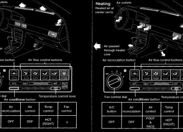
turns the fan on and off, and
CONTROLS Fan control dial This dial controls fan speed. Air flow control buttons These buttons allow you to select the air flow outlets.
— Air flows from center and side
ventilators.
— Air flows from center and side
ventilators and foot outlets.
— Air flows mainly from foot outlets. — Air flows from defroster outlets
and foot outlets.
— Air flows mainly from defroster
outlets.
Temperature control lever This lever allows you to adjust the tempera- ture of the outlet air. Air recirculation button Off position: Outside air is drawn into the passenger compartment and distributed through the selected outlet. Use the off position for normal heater or air conditioner operation. On position (Indicator light on): Interior air is recirculated inside the vehicle. Push the air recirculation button to the ON position when driving on a dusty road, to avoid traffic fumes, and for maximum cool- ing when using the air conditioner. Air conditioner button (If so equipped) This button is provided only on vehicles equipped with an air conditioner. Start the engine, move the fan control dial to
3-3
the desired (1 to 4) position and push the A/C button to turn on the air conditioner. The indicator light comes on when the air conditioner is on. To stop the air condi- tioner, push the switch again. The air conditioner cooling function op- erates only when the engine is running. HEATER OPERATION Heating This mode is used to direct heated air from the foot outlets. Some air also flows from the defroster outlets. 1. Push the air recirculation button to the off
position for normal heating.
2. Push the 3. Move the fan control dial to the desired
button in.
position.
4. Move the temperature control lever to the desired position between the middle and the HOT position.
Ventilation This mode directs outside air to the side and center ventilators.
Z X
1. Push the air recirculation button to the off
position. 2. Push the 3. Move the fan control dial to the desired
button in.
position.
4. Move the temperature control lever to the
desired position.
Defrosting or defogging This mode is used to defrost/defog the windows. 1. Push the 2. Move the fan control dial to the desired
button in.
position.
3. Move the temperature control lever to the desired position between the middle and the HOT position.
c To quickly remove ice or fog from the windows, turn on the fan control dial to 4
and the temperature control lever to the full HOT position.c When the
switch is pushed, the air conditioner automatically turns on to de- fog the windshield, and the air recircula- tion mode automatically turns off.
Outside air is drawn into the passenger compartment to improve the defogging performance.
Bi-level heating/cooling This mode directs air from the side, center and foot outlets. 1. Push the air recirculation button to the off
position. 2. Push the