- 2006 Nissan 350z Owners Manuals
- Nissan 350z Owners Manuals
- 2005 Nissan 350z Owners Manuals
- Nissan 350z Owners Manuals
- 2004 Nissan 350z Owners Manuals
- Nissan 350z Owners Manuals
- 2007 Nissan 350z Owners Manuals
- Nissan 350z Owners Manuals
- 2003 Nissan 350z Owners Manuals
- Nissan 350z Owners Manuals
- 2008 Nissan 350z Owners Manuals
- Nissan 350z Owners Manuals
- Download PDF Manual
-
properly.)
SEAT BELT MAINTENANCE 쐌 To clean the seat belt webbings, apply a mild soap solution or any solution recom- mended for cleaning upholstery or carpets. Then brush the webbing, wipe it with a cloth and allow it to dry in the shade. Do not allow the seat belts to retract until they are com- pletely dry.
쐌 If dirt builds up in the shoulder belt guide of the seat belt anchors, the seat belts may retract slowly. Wipe the shoulder belt guide with a clean, dry cloth.
쐌 Periodically check to see that the seat belt and the metal components such as buckles, tongues, retractors, flexible wires and anchors work properly. If loose parts, deterioration, cuts or other damage on the webbing is found, the entire belt assembly should be replaced.
CHILD RESTRAINTS
PRECAUTIONS ON CHILD RESTRAINTS
WARNING
The information in this section is pro- vided only for those owners who have received permission to install an air bag ON/OFF switch and the switch has been installed. See “Obtaining an air bag ON/OFF switch” earlier in this manual. Never let children 12 or under ride in this vehicle unless an air bag ON/OFF switch is installed and it is being prop- erly used.
WARNING
쐌 Infants and small children should al- ways be placed in an appropriate child restraint while riding in the ve- hicle. Failure to use a child restraint can result in serious injury or death. 쐌 Infants and small children should never be carried on your lap. It is not
Safety — Seats, seat belts and supplemental restraint system 1-17
墌 05.10.18/Z33-D/V5.0 墍
possible for even the strongest adult to resist the forces of a severe acci- dent. The child could be crushed be- tween the adult and parts of the ve- hicle. Also, do not put the same seat belt around both your child and your- self.
쐌 Never install a child restraint in the front seat unless an air bag ON/OFF switch has been installed and the air bag has been turned OFF. An inflat- ing supplemental air bag could seri- ously injure or kill your child.
쐌 An improperly installed child re- straint could lead to serious injury or death in an accident.
CAUTION
For Roadster models, when installing a child restraint, be sure to turn off the automatic passenger seatback tilt func- tion with the seatback tilt cancel switch (located on the back of the passenger
seatback). Otherwise, the child restraint may be damaged. See “Tilting and re- clining passenger’s seat from driver’s seat” earlier in this section for detailed information.
In general, child restraints are designed to be installed with the lap portion of a lap/shoulder seat belt. The proper restraint depends on the child’s size. Generally, infants (up to about 1 year and less than 20 lb (9 kg)) should be placed in rear facing child restraints. Front facing child restraints are available for children who outgrow rear facing child restraints. Child restraints for infants and children of various sizes are offered by several manufacturers. When selecting any child restraint, keep the following points in mind: 쐌 choose only a restraint with a label certifying that it complies with Federal Motor Vehicle Safety Standard 213 or Canadian Motor Vehicle Safety Standard 213.
쐌 check the child restraint in your vehicle to be sure it is compatible with the vehicle’s seat and seat belt system.
쐌 if the child restraint is compatible with your
1-18 Safety — Seats, seat belts and supplemental restraint system
vehicle, place your child in the child restraint and check the various adjustments to be sure the child restraint is compatible with your child. Choose a child restraint that is de- signed for your child’s height and weight. Always follow all recommended procedures. All US states and Canadian provinces re- quire that infants and small children be restrained in approved child restraints at all times while the vehicle is being oper- ated.
WARNING
쐌 Improper use of a child restraint can increase the risk or severity of injury for both the child and other occu- pants of the vehicle.
쐌 Follow all of the child restraint manu- facturer’s instructions for installation and use. When purchasing a child restraint, be sure to select one which will fit your child and vehicle. It may not be possible to properly install some types of child restraints in your vehicle.
墌 05.10.18/Z33-D/V5.0 墍
around in case of a sudden stop or accident.
CAUTION
Remember that a child restraint left in a closed vehicle can become very hot. Check the seating surface and buckles before placing your child in the child restraint.
쐌 If the child restraint is not anchored properly, the risk of a child being injured in a collision or a sudden stop greatly increases.
쐌 Adjustable seatbacks should be po- sitioned to fit the child restraint, but as upright as possible.
쐌 After attaching the child restraint, test it before you place the child in it. Push it from side to side. Try to tug it forward and check to see if the belt holds the restraint in place. If the restraint is not secure, tighten the belt as necessary. You may need to try a different child restraint. Not all child restraints fit in all types of ve- hicles.
쐌 If you install a front facing child re- straint in the front seat, see “Child restraint installation on front passen- ger seat” later in this section.
쐌 When your child restraint is not in use, keep it secured with a seat belt from being thrown to prevent
it
Safety — Seats, seat belts and supplemental restraint system 1-19
墌 05.10.18/Z33-D/V5.0 墍
straint could tip over or otherwise be unsecured and cause injury to the child in a sudden stop or collision.
CAUTION
Turn off the automatic passenger seat- back tilt function by turning the seat- back tilt cancel switch to the CANCEL position. (Roadster models)
CHILD RESTRAINT INSTALLATION ON FRONT PASSENGER SEAT
WARNING
쐌 Never install a child restraint in the front passenger seat unless an air bag ON/OFF switch has been in- stalled and the air bag has been turned OFF. Supplemental front air bags inflate with great force. A child restraint could be struck by the
SSS0261
supplemental front air bag in a crash and could seriously injure or kill your child.
쐌 The three-point seat belt in your ve- hicle is equipped with an automatic locking mode retractor which must be used when installing a child re- straint.
쐌 Failure to use the retractor’s locking mode will result in the child restraint not being properly secured. The re-
1-20 Safety — Seats, seat belts and supplemental restraint system
墌 05.10.18/Z33-D/V5.0 墍
child. Always follow the restraint manufactur- er’s instructions. The back of the child restraint should be secured against the vehicle seatback. If nec- essary, adjust or remove the head restraint to obtain the correct child restraint fit. See “Head restraint adjustment” earlier in this section. If the head restraint is removed, store it in a secure place. Be sure to install the head restraint when the child restraint is If the seating position does not removed. have an adjustable head restraint and it is interfering with the proper child restraint fit, try a different child restraint.
SSS0301C
Front facing — step 2
Front facing If you must install a child restraint in the front seat, follow these steps:
1. Turn the air bag ON/OFF switch to the OFF
position.
Turn the seatback tilt cancel switch to the CANCEL position. (Roadster models only)
2. Position the child restraint on the front pas- senger seat. Move the seat to the rear- most position. Adjust the head restraint to its highest position (if so equipped). The direction of the child restraint depends on the type of the child restraint and the size of the
SSS0253D
Front facing — step 3
3. Route the seat belt tongue through the child restraint and insert it into the buckle until you hear and feel the latch engage. Be sure to follow the child restraint manufacturer’s in- structions for belt routing.
Safety — Seats, seat belts and supplemental restraint system 1-21
墌 05.10.18/Z33-D/V5.0 墍
SSS0254D
Front facing — step 4
4. Pull on the shoulder belt until all of the belt is fully extended. At this time, the belt retractor is in the automatic locking mode (child re- straint mode). It reverts back to emergency locking mode when the belt is fully retracted.
Front facing — step 5
5. Allow the belt to retract. Pull up the belt to
remove any slack in the belt.
SSS0331D
SSS0302B
Front facing — step 6
6. Before placing the child in the child restraint, use force to push the child restraint from side to side, and tug it forward to make sure that it is securely held in place. It should not move more than 1 in (25 mm). If it does move more than 1 in (25 mm), pull again on the shoulder belt to further tighten the child restraint. If unable to properly secure the restraint, try a different child restraint. Not all child restraints fit in all types of vehicles.
1-22 Safety — Seats, seat belts and supplemental restraint system
7. Check that the retractor is in the automatic locking mode by trying to pull more belt out of the retractor. If you cannot pull any more belt webbing out of the retractor, the belt is in the automatic locking mode.
墌 05.10.18/Z33-D/V5.0 墍
8. Check to make sure that the child restraint is properly secured prior to each use. If the lap belt is not locked, repeat steps 4 through 7. After the child restraint is removed and the seat belt is allowed to wind back into the retractor, the automatic locking mode (child restraint mode) is canceled.
SSS0211A
Rear facing — step 2
Rear facing When you install a child restraint in the front seat, follow these steps:
1. Turn the air bag ON/OFF switch to the OFF
position.
Turn the seatback tilt cancel switch to the CANCEL position. (Roadster models only)
2. Position the child restraint on the front pas- senger seat. Move the seat to the rearmost position. The direction of the child restraint depends on the type of the child restraint and the size of the child. Always follow the re- straint manufacturer’s instructions.
SSS0212A
Rear facing — step 3
3. Route the seat belt tongue through the child restraint and insert it into the buckle until you hear and feel the latch engage. Be sure to follow the child restraint manufac- turer’s instructions for belt routing.
Safety — Seats, seat belts and supplemental restraint system 1-23
墌 05.10.18/Z33-D/V5.0 墍
SSS0213A
Rear facing — step 4
4. Pull on the shoulder belt until all of the belt is fully extended. At this time, the belt retractor is in the automatic locking mode (child re- straint mode). It reverts back to emergency locking mode when the belt is fully retracted.
Rear facing — step 5
5. Allow the belt to retract. Pull up the belt to
remove any slack in the belt.
SSS0214A
SSS0215A
Rear facing — step 6
6. Before placing the child in the child restraint, use force to push the child restraint from side to side, and tug it forward to make sure that it is securely held in place. It should not move more than 1 in (25 mm). If it does move more than 1 in (25 mm), pull again on the shoulder belt to further tighten the child restraint. If unable to properly secure the restraint, try a different child restraint. Not all child restraints fit in all types of vehicles.
1-24 Safety — Seats, seat belts and supplemental restraint system
7. Check that the retractor is in the automatic locking mode by trying to pull more belt out of the retractor. If you cannot pull any more belt webbing out of the retractor, the belt is in the automatic locking mode.
墌 05.10.18/Z33-D/V5.0 墍
8. Check to make sure that the child restraint is properly secured prior to each use. If the belt is not locked, repeat steps 4 through 7.
After the child restraint is removed and the seat belt is allowed to wind back into the retractor, the automatic locking mode (child restraint mode) is canceled.
anchor bracket. Tighten the strap according to manufacturer instructions to remove any slack.
WARNING
Child restraint anchor point is designed to withstand only those loads imposed by correctly fitted child restraints. Under no circumstance is it to be used for adult seat belts or harnesses.
SSS0207
TOP TETHER STRAP CHILD RESTRAINT (Coupe models) An anchor for a child restraint with a top tether is provided in this vehicle. However, a child restraint of this type should not be used in this vehicle unless an air bag ON/OFF switch has been installed and is being properly used. See “Obtaining an air bag ON/OFF switch” earlier in this manual. If your child restraint has a top tether strap, it must be secured to the provided anchor point. Secure the child restraint with the seat belt. the head Guide the top tether strap under restraint as illustrated, and secure it to the
Safety — Seats, seat belts and supplemental restraint system 1-25
墌 05.10.18/Z33-D/V5.0 墍
BOOSTER SEATS
PRECAUTIONS ON BOOSTER SEATS
WARNING
쐌 The information in this section is pro- vided only for those owners who have received permission to install an air bag ON/OFF switch and the switch has been installed. See “Ob- taining an air bag ON/OFF switch” earlier in this manual. Never let chil- dren 12 or under ride in this vehicle unless an air bag ON/OFF switch is installed and it is being properly used.
쐌 Infants and small children should al- ways be placed in an appropriate child restraint while riding in the ve- hicle. Failure to use a child restraint or booster seat can result in serious injury or death.
쐌 Infants and small children should never be carried on your lap. It is not possible for even the strongest adult to resist the forces of a severe acci-
dent. The child could be crushed be- tween the adult and parts of the ve- hicle. Also, do not put the same seat belt around both your child and your- self.
쐌 Never install a booster seat in the front seat unless an air bag ON/OFF switch has been installed and the air bag has been turned OFF. An inflat- ing supplemental air bag could seri- ously injure or kill your child.
쐌 A booster seat must only be installed in a seating position that has a lap/shoulder belt. Failure to use a three-point type seat belt with a booster seat can result in a serious injury in sudden stop or collision.
쐌 An improperly installed booster seat could lead to serious injury or death in an accident.
SPA1644
Anchor point location The anchor point 쎻A is located on the luggage area floor. A flap is provided in the carpet for easy access and is marked with the label shown. If you have any questions when installing a top tether strap child restraint on the pas- senger seat, consult a NISSAN dealer for details.
1-26 Safety — Seats, seat belts and supplemental restraint system
墌 05.10.18/Z33-D/V5.0 墍
LRS0455
SSS0363
WARNING
Do not use towels, books, pillows or other items in place of a booster seat. Items such as these may move during normal driving or a collision and result in serious injury or death. Booster seats are designed to be used with a lap/shoulder belt. Booster seats are de- signed to properly route the lap and shoulder portions of the seat belt over the strongest portions of a child’s body
to provide the maximum protection dur- ing a collision.
Booster seats of various sizes are offered by several manufacturers. When selecting any booster seat, keep the following points in mind: 쐌 Choose only a booster seat with a label certifying that it complies with Federal Motor Vehicle Safety Standard 213 or Canadian Motor Vehicle Safety Standard 213.
쐌 Check the booster seat in your vehicle to be sure it is compatible with the vehicle’s seat and seat belt system.
LRS0454
쐌 Make sure the child’s head will be properly supported by the booster seat or vehicle seat. The seatback must be at or above the center of the child’s ears. For example, if a low back booster seat 쎻1
is chosen, the vehicle seatback must be at or above the center of the child’s ears. If the seatback is lower than the center of the child’s ears, a high back booster seat 쎻2 should be used. 쐌 If the booster seat is compatible with your vehicle, place your child in the booster seat and check the various adjustments to be sure the booster seat is compatible with your child. Always follow all recommended proce- dures.Safety — Seats, seat belts and supplemental restraint system 1-27
墌 05.10.18/Z33-D/V5.0 墍
before placing your child in the booster seat.
All U.S. states and Canadian provinces or territories require that infants and small children be restrained in an approved child restraint at all times while the vehicle is being operated.
WARNING
쐌 Improper use of a booster seat can increase the risk or severity of injury for both the child and other occu- pants of the vehicle.
쐌 Follow all of the booster seat manu- facturer’s instructions for installation and use. When purchasing a booster seat, be sure to select one which will fit your child and vehicle. It may not be possible to properly install some types of booster seats in your ve- hicle.
쐌 If the booster seat and seat belt are not used properly, the risk of a child being injured in a collision or a sud- den stop greatly increases.
쐌 Adjustable seatbacks should be po- sitioned to fit the booster seat, but as
upright as possible.
쐌 After placing the child in the booster seat and fastening the seat belt, make sure the shoulder portion of the belt is away from the child’s face and neck and the lap portion of the belt does not cross the abdomen.
쐌 Do not put the shoulder belt behind the child or under the child’s arm. If you must install a booster seat in the front seat, see “Booster seat instal- lation on front passenger seat” later in this section.
쐌 When your booster seat is not in use, keep it secured with a seat belt to prevent it from being thrown around in case of a sudden stop or accident.
CAUTION
Remember that a booster seat left in a closed vehicle can become very hot. Check the seating surface and buckles
1-28 Safety — Seats, seat belts and supplemental restraint system
墌 05.10.18/Z33-D/V5.0 墍
6. Pull the shoulder belt portion of the seat belt toward the retractor to take up extra slack. Be sure the shoulder belt is positioned across the top, middle portion of the child’s shoul- der. Be sure to follow the booster seat manu- facturer’s instructions for adjusting the belt routing.
7. Follow the warnings, cautions and instruc- tions for properly fastening a seat belt shown in the “Three-point type seat belt with retrac- tor” earlier in this section.
could seriously injure or kill your child.
If you must install a booster seat in the front seat, follow these steps:
1. Turn the air bag ON/OFF switch to the OFF
position.
2. Move the seat to the rearmost position. 3. Position the booster seat on the seat. Only place it in a front facing direction. Always follow the booster seat manufacturer’s in- structions.
4. The booster seat should be positioned on the vehicle seat so that it is stable. If necessary, adjust or remove the head restraint to obtain the correct booster seat fit. See “Head re- straint adjustment” earlier in this section. If the head restraint is removed, store it in a secure place. Be sure to install the head restraint when the booster seat is removed. If the seating position does not have an adjust- able head restraint and it is interfering with the proper booster seat fit, try a different booster seat.
5. Position the lap portion of the seat belt low and snug on the child’s hips. Be sure to follow the booster seat manufacturer’s in- structions for adjusting the belt routing.
BOOSTER SEAT INSTALLATION ON FRONT PASSENGER SEAT
LRS0454
WARNING
Never install a booster seat in the front passenger seat unless an air bag ON/OFF switch has been installed and the air bag has been turned OFF. Supplemental air bags inflate with great force. A child could be struck by the supplemental air bag in a crash and
Safety — Seats, seat belts and supplemental restraint system 1-29
墌 05.10.18/Z33-D/V5.0 墍
by the driver and passenger seat belts and is not a substitute for them. Seat belts should always be correctly worn and the occupant seated a suitable distance away from the steer- ing wheel, instrument panel, door finishers and side roof rails. (See “Seat belts” earlier in this section for instructions and precautions on seat belt usage.) The supplemental air bags operate only when the ignition switch is in the ON or START position. After turning the ignition key to the ON position, the supplemental air bag warning light illuminates. The supplemental air bag warning light will turn off after about 7
seconds if the systems are operational.SUPPLEMENTAL RESTRAINT SYSTEM PRECAUTIONS ON SUPPLEMENTAL RESTRAINT SYSTEM This Supplemental Restraint System (SRS) sec- tion contains important information concerning the driver and passenger front impact supple- mental air bags, front seat side-impact supple- mental air bags, curtain side-impact air bags and front seat pre-tensioner seat belts. Supplemental front-impact air bag system: This system can help cushion the impact force to the face and chest of the driver and front passenger in certain frontal collisions. Supplemental side-impact air bag system (if so equipped): This system can help cushion the impact force to the chest area of the driver and front passenger in certain side impact colli- sions. The front seat side-impact supplemental air bags are designed to inflate on the side where the vehicle is impacted. Supplemental curtain side-impact air bag system (if so equipped for Coupe models): This system can help cushion the impact force to the head of occupants in certain side impact collisions. The curtain side-impact air bags are designed to inflate on the side where the vehicle is impacted. The supplemental restraint system is designed to supplement the crash protection provided 1-30 Safety — Seats, seat belts and supplemental restraint system
墌 05.10.18/Z33-D/V5.0 墍
from the steering wheel or instru- ment panel. Always use the seat belts.
쐌 The driver and front passenger seat belt buckles are equipped with sen- sors that detect if the seat belts are fastened. The air bag system moni- tors the severity of a collision and then inflates the air bags based on belt usage. Failure to properly wear seat belts can increase the risk or severity of injury in an accident.
쐌 Keep hands on the outside of the steering wheel. Placing them inside the steering wheel rim could increase the risk that they are injured when the supplemental front air bag in- flates.
WARNING
쐌 The supplemental front air bags ordi- narily will not inflate in the event of a side impact, rear impact, rollover, or lower severity frontal collision. Al- ways wear your seat belts to help reduce the risk or severity of injury in various kinds of accidents.
쐌 The seat belts and the supplemental front air bags are most effective
SSS0131
when you are sitting well back and upright in the seat. Supplemental front air bags inflate with great force. If you are unrestrained, leaning for- ward, sitting sideways or out of posi- tion in any way, you are at greater risk of injury or death in a crash. You may also receive serious or fatal in- juries from the supplemental front air bag if you are up against it when it inflates. Always sit back against the seatback and as far away as practical
Safety — Seats, seat belts and supplemental restraint system 1-31
墌 05.10.18/Z33-D/V5.0 墍
SSS0132
SSS0016
1-32 Safety — Seats, seat belts and supplemental restraint system
墌 05.10.18/Z33-D/V5.0 墍
SSS0006
SSS0008
SSS0099
SSS0007
SSS0009
SSS0100
Safety — Seats, seat belts and supplemental restraint system 1-33
墌 05.10.18/Z33-D/V5.0 墍
WARNING
쐌 Never let children 12 or under ride in this vehicle. Do not attempt to hold them in your lap or arms. Some ex- amples of dangerous riding positions are shown in the previous illustra- tions.
쐌 Children may be severely injured or killed when the supplemental front air bags or supplemental side and curtain side-impact air bags (if so equipped) inflate.
쐌 Also, never install a child restraint in the front seat. An inflating supple- mental front air bag could seriously injure or kill your child.
쐌 For information about installing an air bag ON/OFF switch in your ve- hicle so children can be transported, see “Obtaining an air bag ON/OFF switch” earlier in this section.
SSS0101
SSS0159
WARNING
Supplemental side air bag and curtain side-impact air bag (if so equipped): 쐌 The supplemental side air bag and curtain side-impact air bag ordinarily will not inflate in the event of a fron- tal impact, rear impact, rollover or lower severity side collision. Always wear your seat belts to help reduce the risk or severity of injury in various kinds of accidents.
쐌 The seat belts, the supplemental side air bags and curtain side-impact air bags are most effective when you are sitting well back and upright in the seat. The side air bag and curtain side-impact air bag inflate with great force. Do not allow anyone to place their hand, leg or face near the side air bag on the side of the seatback of the front seat or near the side roof rails. Do not allow anyone sitting in the front seat to extend their hand
1-34 Safety — Seats, seat belts and supplemental restraint system
墌 05.10.18/Z33-D/V5.0 墍
SSS0162
SSS0276
out of the window or lean against the door. Some examples of dangerous riding positions are shown in the pre- vious illustrations.
쐌 Do not use seat covers on the front seatbacks. They may interfere with supplemental side air bag inflation.
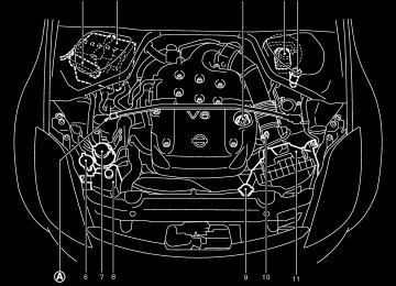
COMPONENTS OF THE SUPPLEMENTAL RESTRAINT SYSTEM 1. Crash zone sensor 2. Supplemental front air bag modules 3. Supplemental curtain side-impact air bag modules (if so equipped for Coupe models)
4. Diagnosis sensor unit 5. Satellite sensors 6. Seat belt pre-tensioner retractor 7. Supplemental side air bag modules (if so
Supplemental front air bag system The driver supplemental air bag is located in the center of the steering wheel; the front passenger supplemental air bag is mounted in the instru- ment panel. These systems are designed to meet optional certification requirements under U.S. regulations. They are also permitted in Canada. The optional certification allows front air bags to be designed to inflate somewhat less forcefully than previously. However, all of the information, cautions and warnings in this manual still apply and must be followed. The front air bags are designed to inflate in higher severity frontal collisions, although they Safety — Seats, seat belts and supplemental restraint system 1-35
equipped)
墌 05.10.18/Z33-D/V5.0 墍
the forces in another
type of may inflate if collision are similar to those of a higher severity frontal impact. They may not inflate in certain frontal collisions. Vehicle damage (or lack of it) is not always an indication of proper supplemental air bag operation. The supplemental air bag system has dual stage inflators for both the driver and passenger air bags. The system monitors information from the crash zone sensor, the diagnosis sensor unit and seat belt buckle switches that detect if the seat belts are fastened, inflator operation is based on the severity of a collision and whether the seat belts are being used. Only one front air bag may inflate in a crash, depending on the crash sever- ity and whether the front occupants are belted or unbelted. This does not indicate improper per- formance of the system. If you have any ques- tions about the performance of your air bag system, contact a NISSAN dealer.
the face and chest of the front occupants. They can help save lives and reduce serious injuries. However, an inflating front air bag may cause facial abrasions or other injuries. Supplemental front air bags do not provide restraint to the lower body. The seat belts should be correctly worn and the driver and passenger seated upright as far as practical away from the steering wheel or instru- ment panel. The supplemental front air bags inflate quickly in order to help protect the front occupants. Because of this, the force of the front air bag inflating can increase the risk of injury if the occupant is too close to, or is against the air bag module during inflation. The air bag will deflate quickly after the collision is over. The supplemental front air bags operate only when the ignition switch is in the ON or START position. After turning the ignition key to the ON position, the supplemental air bag warning light illuminates. The supplemental air bag warning light will turn off after about 7
seconds if the system is operational.When the supplemental front air bag inflates, a fairly loud noise may be heard, followed by release of smoke. This smoke is not harmful and does not indicate a fire. Care should be taken not to inhale it, as it may cause irritation and choking. Those with a history of a breathing condition should get fresh air promptly. Supplemental front air bags, along with the use of seat belts, help to cushion the impact force on 1-36 Safety — Seats, seat belts and supplemental restraint system
WARNING
쐌 Do not place any objects on the steering wheel pad or on the instru- ment panel. Also, do not place any objects between any occupant and the steering wheel or instrument panel. Such objects may become dangerous projectiles and cause in- jury if the supplemental front air bag inflates.
쐌 Immediately after inflation, several front air bag system components will be hot. Do not touch them; you may severely burn yourself.
쐌 No unauthorized changes should be made to any components or wiring of the supplemental air bag system. This is to prevent accidental inflation of the supplemental air bag or dam- age to the supplemental air bag sys- tem.
쐌 Do not make unauthorized changes to your vehicle’s electrical system, suspension system or front end
墌 05.10.18/Z33-D/V5.0 墍
structure. This could affect proper operation of the supplemental front air bag system.
쐌 Tampering with the supplemental front air bag system may result in serious personal injury. Tampering includes changes to the steering wheel and the instrument panel as- sembly by placing material over the steering wheel pad and above the instrument panel or by installing ad- ditional trim material around the air bag system.
쐌 Work around and on the supplemen- tal front air bag system should be done by a NISSAN dealer. Installa- tion of electrical equipment should also be done by a NISSAN dealer. The yellow and orange Supplemental Restraint System (SRS) wiring and connectors should not be modified or disconnected. Unauthorized electri- cal test equipment and probing de- vices should not be used on the air bag system.
쐌 A cracked windshield should be re- placed immediately by a qualified re- pair facility. A cracked windshield could affect the supplemental air bag system.
the function of
쐌 The SRS wiring harness connectors are yellow and orange for easy iden- tification.
When selling your vehicle, we request that you inform the buyer about the supplemental front air bag system and guide the buyer to the appro- priate sections in this Owner’s Manual.
SSS0209A
Supplemental side air bag and curtain side-impact air bag systems (if so equipped) This section includes the information about both the supplemental side air bag system 쎻A and the supplemental curtain side-impact air bag system 쎻B . Curtain side-impact air bags are not avail- able on Roadster models. The supplemental side air bags are located in the outside of the seatback of the front seats. The supplemental curtain side-impact air bags are located in the side roof rails. These systems are designed to meet voluntary guidelines to help reduce the risk of injury to out-of-position Safety — Seats, seat belts and supplemental restraint system 1-37
墌 05.10.18/Z33-D/V5.0 墍
impact air bags do not provide restraint to the lower body. The seat belts should be correctly worn and the driver and passenger seated upright as far as practical away from the side air bag, and seated as far away as practical from the door finishers and side roof rails. The side air bags and curtain side-impact air bag inflate quickly in order to help protect the front occupants. Because of this, the force of the side air bag and curtain side-impact air bag inflating can increase the risk of injury if the occupant is too close to, or is against these air bag modules during inflation. The side air bag and curtain side-impact air bag will deflate quickly after the collision is over. The supplemental side air bags and curtain side-impact air bags operate only when the ignition switch is in the ON or START po- sition. After turning the ignition key to the ON position, the supplemental air bag warning light illuminates. The air bag warning light will turn off after about 7 seconds if the systems are operational.
occupants. However, all of the information, cautions and warnings in this manual still apply and must be followed. The supplemen- tal side air bags and curtain side-impact air bags are designed to inflate in higher severity side collisions, although they may inflate if the forces in another type of collision are similar to those of a higher severity side impact. They are designed to inflate on the side where the vehicle is impacted. They may not inflate in certain side collisions. Vehicle damage (or lack of it) is not always an indication of proper supplemental side air bag and curtain side-impact air bag opera- tion. When the supplemental side air bag and curtain side-impact air bag inflate, a fairly loud noise may be heard, followed by release of smoke. This smoke is not harmful and does not indicate a fire. Care should be taken not to inhale it, as it may cause irritation and choking. Those with a history of a breathing condition should get fresh air promptly. Supplemental side air bags, along with the use of seat belts, help to cushion the impact force on the chest of the front occupants. Curtain side- impact air bags help to cushion the impact force to the head of occupants. They can help save lives and reduce serious injuries. However, an inflating side air bag and curtain side-impact air bag may cause abrasions or other injuries. Supplemental side air bags and curtain side- 1-38 Safety — Seats, seat belts and supplemental restraint system
WARNING
쐌 Do not place any objects near the seatback of the front seats. Also, do not place any objects (an umbrella, bag, etc.) between the front door fin- isher and the front seat. Such objects may become dangerous projectiles and cause injury if the side air bag inflates.
쐌 Right after inflation, several side air bag and curtain side-impact air bag system components will be hot. Do not touch them; you may severely burn yourself.
쐌 No unauthorized changes should be made to any components or wiring of the side air bag and curtain side- impact air bag system. This is to pre- vent accidental inflation of the side air bag and curtain side-impact air bag or damage to the side air bag and curtain side-impact air bag sys- tem.
쐌 Do not make unauthorized changes
墌 05.10.18/Z33-D/V5.0 墍
to your vehicle’s electrical system, suspension system or side panel. This could affect proper operation of the supplemental side air bag and curtain side-impact air bag system.
쐌 Tampering with the supplemental side air bag system may result in serious personal injury. For example, do not change the front seats by placing material near the seatback or by installing additional trim material, such as seat covers, around the side air bag.
Installation of
쐌 Work around and on the side air bag and curtain side-impact air bag sys- tem should be done by a NISSAN dealer. electrical equipment should also be done by a NISSAN dealer. The SRS wiring har- nesses* should not be modified or disconnected. Unauthorized electri- cal test equipment and probing de- vices should not be used on the side air bag system.
* The SRS wiring harnesses are cov-
ered with yellow insulation either just before the harness connectors or over the complete harness for easy identification.
When selling your vehicle, we request that you inform the buyer about the side air bag and curtain side-impact air bag system and guide the buyer to the appropriate sections in this Owner’s Manual. Pre-tensioner seat belt system
WARNING
쐌 The pre-tensioner seat belt cannot be reused after activation. It must be replaced together with the retractor and buckle as a unit.
쐌 If the vehicle becomes involved in a frontal collision but the pre-tensioner is not activated, be sure to have the pre-tensioner system checked and, if necessary, replaced by a NISSAN dealer.
쐌 No unauthorized changes should be
made to any components or wiring of the pre-tensioner seat belt system. This is to prevent accidental activa- tion of the pre-tensioner seat belt or damage to the pre-tensioner seat belt operation. Tampering with the pre-tensioner seat belt system may result in serious personal injury.
쐌 Work around and on the pre- tensioner system should be done by a NISSAN dealer. Installation of elec- trical equipment should also be done by a NISSAN dealer. Unauthorized electrical test equipment and probing devices should not be used on the pre-tensioner seat belt system.
쐌 If you need to dispose of the pre- tensioner or scrap the vehicle, con- tact a NISSAN dealer. Correct pre- tensioner disposal procedures are set forth in the appropriate NISSAN Service Manual. Incorrect disposal procedures could cause personal injury.
The front seat pre-tensioner seat belt system
Safety — Seats, seat belts and supplemental restraint system 1-39
墌 05.10.18/Z33-D/V5.0 墍
activates in conjunction with the front supple- mental air bag systems. Working with the seat belt retractor, it helps tighten the seat belt when the vehicle becomes involved in certain types of collisions, helping to restrain front seat occu- pants.
The pre-tensioner is encased with the seat belt’s retractor. These seat belts are used the same as conventional seat belts.
When the pre-tensioner seat belt activates, smoke is released and a loud noise may be heard. The smoke is not harmful, but care should be taken not to inhale it as it may cause irritation and choking. Those with a history of a breathing condition should get fresh air promptly.
If any abnormality occurs in the pre-tensioner seat belt system, the supplemental air bag warn- will not come on, will flash inter- ing light mittently or will turn on for 7 seconds and remain on after the ignition key has been turned to the ON or START position. In this case, the pre- tensioner seat belt may not function properly. They must be checked and repaired. Take your vehicle to a NISSAN dealer.
SUPPLEMENTAL AIR BAG WARNING LABELS Warning labels about the supplemental air bag system are placed in the vehicle as shown in the illustration.
SSS0206
When selling your vehicle, we request that you inform the buyer about the pre-tensioner seat belt system and guide the buyer to the appro- priate sections in this Owner’s Manual. 1-40 Safety — Seats, seat belts and supplemental restraint system
墌 05.10.18/Z33-D/V5.0 墍
the supplemental air bag warning light illumi- nates. The supplemental air bag warning light will turn off after about 7 seconds if the system is operational.
the following conditions occur,
If any of the supplemental front air bag, supplemental side air bag and curtain side-impact air bag systems, and pre-tensioner seat belt need servicing: 쐌 The supplemental air bag warning light re-
mains on after approximately 7 seconds.
쐌 The supplemental air bag warning light
flashes intermittently.
SPA1097
쐌 The supplemental air bag warning light does
the supplemental
SUPPLEMENTAL AIR BAG WARNING LIGHT The supplemental air bag warning light, display- in the instrument panel, monitors the ing circuits of front air bag, supplemental side air bag (if so equipped) and curtain side-impact air bag (if so equipped for Coupe models) systems, and pre-tensioner seat belt. The circuits monitored by the air bag warn- ing light are the diagnosis sensor unit, satellite sensors, front air bag modules, side air bag modules, curtain side-impact air bag modules, pre-tensioner seat belt and all related wiring. After turning the ignition key to the ON position,
not come on at all.
Under these conditions, the supplemental front air bags, supplemental side air bags, curtain side-impact air bags and/or pre-tensioner seat belt may not operate properly. They must be checked and repaired. Take your vehicle to a NISSAN dealer.
WARNING
If the supplemental air bag warning light the
it could mean that
is on,
supplemental front air bag, supplemen- tal side air bag, curtain side-impact air bag systems and/or pre-tensioner seat belt systems will not operate in an acci- dent. To help avoid injury to yourself or others, have your vehicle checked by a NISSAN dealer as soon as possible.
Repair and replacement procedure The supplemental front air bags, supplemental side air bags (if so equipped), curtain side- impact air bags (if so equipped for Coupe models) and pre-tensioner seat belt are de- signed to inflate on a one-time-only basis. As a reminder, unless it is damaged, the supplemen- tal air bag warning light will remain illuminated after inflation has occurred. Repair and replace- ment of these systems should be done only by a NISSAN dealer. When maintenance work is required on the vehicle, the supplemental front air bags, side air bags, curtain side-impact air bags, related parts and pre-tensioner seat belt should be pointed out to the person conducting the maintenance. The ignition key should always be in the LOCK position when working under the hood or inside the vehicle.
Safety — Seats, seat belts and supplemental restraint system 1-41
墌 05.10.18/Z33-D/V5.0 墍
Correct disposal procedures are set forth in the appropriate NISSAN Ser- vice Manual. Incorrect disposal pro- cedures could cause personal injury.
WARNING
쐌 Once a supplemental front air bag, supplemental side air bag or curtain side-impact air bag has inflated, the air bag module will not function again and must be replaced. Addi- tionally, if any of the supplemental front air bags inflate, the activated pre-tensioner seat belts must also be replaced. The air bag module and pre-tensioner system should be replaced by a NISSAN dealer. The air bag module and pre- tensioner seat belt system cannot be repaired.
seat
belt
쐌 The supplemental front air bag and side air bag, curtain side-impact air bag systems and pre-tensioner seat belt system should be inspected by a NISSAN dealer if there is any damage to the front end or side portion of the vehicle.
쐌 If you need to dispose of
these supplemental systems or scrap the vehicle, contact a NISSAN dealer.
1-42 Safety — Seats, seat belts and supplemental restraint system
墌 05.10.18/Z33-D/V5.0 墍
MEMO
Safety — Seats, seat belts and supplemental restraint system 1-43
墌 05.10.18/Z33-D/V5.0 墍
2 Instruments and controls
Instrument panel ................................................................... 2-2
Meters and gauges .............................................................. 2-3
Speedometer and odometer ........................................ 2-4
Tachometer ....................................................................... 2-5
Engine coolant temperature gauge ............................ 2-6
Fuel gauge ........................................................................ 2-6
Engine oil pressure gauge ........................................... 2-7
Volt meter ......................................................................... 2-8
Trip computer .................................................................. 2-8
Warning/indicator lights and audible reminders ........ 2-12
Checking bulbs ............................................................. 2-12
Warning lights ............................................................... 2-12
Indicator lights ............................................................... 2-16
Audible reminders ........................................................ 2-18
Security systems ................................................................ 2-19
Vehicle security system .............................................. 2-19
NISSAN vehicle immobilizer system ....................... 2-20
Windshield wiper and washer switch ........................... 2-22
Rear window wiper and washer switch (Coupe models) .................................................................. 2-23
Rear window and outside mirror defroster switch .... 2-24
Headlight and turn signal switch ................................... 2-24
Xenon headlights .......................................................... 2-24
Headlight switch ........................................................... 2-25Daytime running light system (Canada only) ........ 2-26
Turn signal switch ........................................................ 2-27
Instrument brightness control ................................... 2-27
Hazard warning flasher switch ....................................... 2-27
Horn ....................................................................................... 2-28
Heated seats (if so equipped) ........................................ 2-28
Vehicle dynamic control (VDC) off switch (if so equipped) .................................................................. 2-29
Traction control system (TCS) off switch (if so equipped) .................................................................. 2-30
Clock ..................................................................................... 2-31
Adjusting the time ........................................................ 2-31
Power outlet ........................................................................ 2-32
Storage ................................................................................. 2-33Instrument pocket (except for navigation system equipped models) ........................................................ 2-33
Sunglasses holder (Coupe models) ........................ 2-33
Card holder .................................................................... 2-34
Cargo net......................................................................... 2-34
Cup holders ................................................................... 2-35
Console box .................................................................. 2-36
Rear floor box ................................................................ 2-36
Rear parcel box ............................................................ 2-37
Stowing golf bags ......................................................... 2-37墌 05.10.18/Z33-D/V5.0 墍
Coat hook (Coupe models).............................................. 2-39
Windows .............................................................................. 2-39
Power windows ............................................................ 2-39
Automatic adjusting function ...................................... 2-41
Interior lights ........................................................................ 2-41
Room light ...................................................................... 2-41
Map lights ...................................................................... 2-41
Vanity mirror light ............................................................... 2-42
Luggage compartment light (Coupe models) ............. 2-42
Trunk light (Roadster models).......................................... 2-43HomeLink universal transceiver (if so equipped) .... 2-43
........................................... 2-44Programming HomeLink Programming HomeLink for Canadian customers ....................................................................... 2-45
Operating the HomeLink universal transceiver.... 2-45
Programming trouble diagnosis ................................ 2-45
Clearing the programmed information .................... 2-46
Reprogramming a single HomeLink button ........ 2-46
If your vehicle is stolen ............................................... 2-46墌 05.10.18/Z33-D/V5.0 墍
INSTRUMENT PANEL
11. Passenger supplemental air bag 12. Side ventilator 13. VDC (Vehicle dynamic control) OFF switch or TCS (Traction control system) OFF switch
14. Soft top operating switch (for Roadster
models)
15. Fuel-filler door opener switch 16. Hood lock release handle 17. Fuse box 18. Tilting steering wheel lock lever 19. 20. Navigation system display* or Instrument
Ignition switch/steering lock
pocket
21. Audio system/Clock 22. Rear window and outside mirror defroster
switch
23. Hazard warning flasher switch 24. Cup holder 25. Heated seat switch (if so equipped) 26. Heater/air conditioner control 27. Power outlet *: Refer
to the separate Navigation System
Owner’s Manual.
1. Headlight/turn signal switch 2. 3. Steering wheel switch for audio control (if so
Instrument brightness control switch
equipped)
4. Driver supplemental air bag/Horn 5. Meters/gauges
SIC2996
6. Cruise control main/set switch
(if so equipped)
7. Trip computer mode/setting switch 8. Wiper/washer switch 9. Center ventilator 10. Card holder
2-2 Instruments and controls
墌 05.10.18/Z33-D/V5.0 墍
METERS AND GAUGES
8. Automatic transmission position indicator or
Manual transmission shift up indicator (See “Driving the vehicle” in the “5. Starting and driving” section.)
9. Reset knob for trip odometer 10. Odometer (Total/Twin trip) 11. Trip computer setting switch
(See “Trip computer” later in this section.)
12. Trip computer mode switch
(See “Trip computer” later in this section.)
Combination meter: 1. Warning/Indicator lights 2. Turn signal/hazard indicator lights 3. Tachometer 4. Speedometer
SIC2233
5.
Instrument brightness control switch (See “Headlight and turn signal switch” later in this section.)
6. Fuel gauge 7. Engine coolant temperature gauge
Instruments and controls 2-3
墌 05.10.18/Z33-D/V5.0 墍
The odometer records the total distance the vehicle has been driven. The twin trip odometer records the distance of individual trips.
Triple meter: 1. Trip computer 2. Engine oil pressure gauge 3. Volt meter
2-4 Instruments and controls
SIC1948
SIC1949A
쎻1 Speedometer 쎻2 Odometer 쎻3 Twin trip odometer 쎻4 Reset knob for trip odometer SPEEDOMETER AND ODOMETER Speedometer The speedometer indicates vehicle speed in miles per hour (MPH) and kilometers per hour (km/h). Odometer/Twin trip odometer The odometer/twin trip odometer are displayed when the ignition switch is in the ON position.
墌 05.10.18/Z33-D/V5.0 墍
Changing the display: Pushing the reset knob changes the display as follows: TRIP A → TRIP B → TRIP A Resetting the trip odometer: Pushing the reset knob for more than 1 second resets the trip odometer to zero.
serious engine damage.
SIC1950A
쎻1 Tachometer 쎻2 Transmission indicator TACHOMETER The tachometer indicates engine speed in revo- lutions per minute (rpm). Do not rev engine into the red zone 쎻A .
CAUTION
When engine speed approaches the red zone, shift to a higher gear. Operating the engine in the red zone may cause
Instruments and controls 2-5
墌 05.10.18/Z33-D/V5.0 墍
CAUTION
If the gauge indicates engine coolant temperature near the hot (H) end of the normal range, reduce vehicle speed to decrease temperature. If the gauge is over the normal range, stop the vehicle as soon as safely possible. If the engine is overheated, continued operation of the vehicle may seriously damage the engine. See “If your vehicle overheats” in the “6. In case of emergency” section for immediate action required.
SIC2556
FUEL GAUGE The gauge indicates the approximate fuel level in the tank. The gauge may move slightly during braking, turning, acceleration, or going up or down hill. The gauge needle is designed to move to the E (Empty) position when the ignition key is turned to the OFF position. Refill the fuel tank before the gauge regis- ters the E (Empty) position.
墌 05.10.18/Z33-D/V5.0 墍
SIC2371A
ENGINE COOLANT TEMPERATURE GAUGE The gauge indicates the engine coolant tem- perature. The engine coolant temperature is within the normal range 쎻A when the gauge needle points within the zone shown in the illustration. The engine coolant temperature will vary with the outside air temperature and driving conditions.
2-6 Instruments and controls
The low fuel warning light comes on when the fuel tank is getting low. Refuel as soon as it is convenient, preferably before the gauge reaches the E position. There will be a small reserve of fuel in the tank when the fuel gauge needle reaches the E position. The the fuel-filler door is located on the passenger’s side of the vehicle.
indicates that
CAUTION
malfunction indicator
쐌 If the vehicle runs out of fuel, the lamp (MIL) may come on. Refuel as soon as possible. After a few driving trips, lamp should turn off. If the the lamp remains on after a few driving trips, have the vehicle inspected by a NISSAN dealer.
쐌 For additional information, see “Mal- function indicator lamp (MIL)” later in this section.
SIC1954A
Type A
ENGINE OIL PRESSURE GAUGE The gauge indicates the engine lubrication sys- tem oil pressure while the engine is running. When the engine speed is high, the engine oil pressure is also high. When it is low, the gauge indicates the low oil pressure.
SIC1953A
Type B
CAUTION
쐌 This gauge is not designed to indi- cate low engine oil level. Use the dipstick to check the oil level. (See “Engine oil” in the “8. Maintenance and do-it-yourself” section.)
쐌 If the gauge needle does not move with the proper amount of engine oil, have the vehicle checked by a NISSAN dealer. Continued vehicle
Instruments and controls 2-7
墌 05.10.18/Z33-D/V5.0 墍
operation in such a condition could cause serious damage to the engine.
SIC1955
SIC2234
VOLT METER When the ignition switch is turned to the ON position, the volt meter indicates the battery voltage; while the engine is running, it indicates the alternator voltage of 11 - 15 volts (normal range 쎻A ). However, while cranking the engine, the volts drop below the normal range. If the needle is not in the normal range 쎻A while the engine is running, it may indicate that the charging system is not functioning properly. Have the system checked by a NISSAN dealer.
TRIP COMPUTER The display of the trip computer is situated in the triple meter. When the ignition switch is turned to ON, the display scrolls all the modes of the trip computer and then shows the mode chosen before the ignition switch is turned OFF.
2-8 Instruments and controls
墌 05.10.18/Z33-D/V5.0 墍
consumption and speed → Elapsed time and trip odometer → Stopwatch → Tire pressure indicator (PSI) → Up-shift indicator setting (for M/T models) → Speed indicator Speed indicator (mph or km/h) The vehicle speed is displayed in MPH or km/h while driving. The speed indicator in the trip computer indicates the reference speed. The actual speed indicated by the speedometer (com- bination meter) may differ from the one in the trip computer. Outside air temperature (ICY — °F or °C) The outside air temperature is displayed in °F or °C in the range of −22 to 131°F (−30 to 55°C). The outside air temperature mode includes a low temperature warning feature: below 37°F (3°C), the outside air temperature mode is automati- cally selected and the ICY indicator will illumi- nate in order to draw the driver’s attention. Push the mode switch 쎻A if you wish to return to the mode that was selected before the warning occurred. The ICY indicator will continue blink- ing as long as the temperature remains below 39°F (4°C). The ambient temperature sensor is located in
SIC2997
Switches for the trip computer are located on the side of the combination meter panel. To operate the trip computer, push the side of the switches as shown above. 쎻A : Trip computer mode switch 쎻B : Trip computer setting switch When the ignition switch is turned to ON, modes of the trip computer can be selected by pushing the trip computer mode switch 쎻A . Each time the mode switch 쎻A is pushed, the display will change as follows: Speed indicator → Outside air temperature (ICY) → Distance to empty (dte) → Average fuel
temperature or
front of the radiator. The sensor may be affected by road or engine heat, wind directions and other driving conditions. The display may differ from the actual ambient the temperature displayed on various signs or bill- boards. Distance to empty (dte — mls or km) The distance to empty (dte) mode provides you with an estimation of the distance that can be driven before refueling. The dte is constantly being calculated, based on the amount of fuel in the fuel tank and the actual fuel consumption. The display is updated every 30 seconds. The dte mode includes a low range warning feature: when the fuel level is low, the dte mode is automatically selected and the digits blink in order to draw the driver’s attention. Press the mode switch 쎻A if you wish to return to the mode that was selected before the warning occurred. The dte indicator will remain blinking until the vehicle is refuelled. When the fuel display will change to (----). NOTE: 쐌 If the amount of fuel added while the ignition switch is OFF is small, the dis- play just before the ignition switch is Instruments and controls 2-9
level drops even lower, the dte
墌 05.10.18/Z33-D/V5.0 墍
turned OFF may continue to be dis- played.
쐌 When driving uphill or rounding curves, the fuel in the tank shifts, which may momentarily change the display.
Average fuel consumption (mpg or l (liter)/100 km) and speed (av. mph or av. km/h) Fuel consumption:
The average fuel consumption mode shows the average fuel consumption since the last reset. Resetting is done by pushing the trip computer setting switch 쎻B for more than approximately 1
second. (The average speed is also reset at the same time.)The display is updated every 30 seconds. At about the first 1/3 miles (500 m) after a reset, the display shows (----). Speed:
The average speed mode shows the average vehicle speed since the last reset. Resetting is done by pushing the setting switch 쎻B for more than approximately 1 second. (The average fuel consumption is also reset at the same time.)
The display is updated every 30 seconds. The
2-10 Instruments and controls
first 30 seconds after a reset, the display shows (----). Elapsed time (h:m:s) and trip odometer (mls or km) Elapsed time:
The elapsed time mode shows the time since the last reset. The displayed time can be reset by pushing the trip computer setting switch 쎻B for more than approximately 1 second. (The trip odometer is also reset at the same time.) Trip odometer: The trip odometer mode shows the total dis- tance the vehicle has been driven since the last reset. Resetting is done by pushing the setting switch 쎻B for more than approximately 1 second. (The elapsed time is also reset at the same time.) Stopwatch (h:m:s) You can use the trip computer as a stopwatch. Each time the trip computer setting switch 쎻B is pushed, the stopwatch will be operated as fol- lows:
After 100 hours, the time will start from the reset display again.
Even if the display is switched to the other mode while the time is starting, the stopwatch contin- ues to advance until you stop the time in the stopwatch mode. When the ignition switch is turned to the OFF position, the time is reset. Tire pressure indicator (PSI) The tire pressure indicator shows tire pressure (0 - 63 psi) of all tires (except the spare tire) by sending a signal from a sensor that is installed in each wheel. Push the trip computer setting switch 쎻B to change the display to F (front) or R (rear). The tire pressure sensor will activate only when the vehicle is driven at speeds above 16 MPH (25 km/h). If the tire pressure signal cannot be received correctly, the display shows (----). The tire pressure indicator mode includes a low If the vehicle is tire pressure warning feature. being driven with low tire pressure, the tire pressure indicator mode is automatically se- lected and the PSI indicator will blink in order to attract the driver’s attention. Push the trip com- puter mode switch 쎻A if you wish to return to the mode that was selected before the warning occurred. The PSI indicator will continue blinking until the tire pressure of each tire is properly adjusted.
墌 05.10.18/Z33-D/V5.0 墍
information, see “Tire pressure For additional monitoring system (TPMS)” in the “5. Starting and driving” section and “Flat tire” in the “6. In case of emergency” section. Tire pressure shown in the display may rise or fall while driving depending on the driv- ing conditions (heat, etc.) and/or the out- side temperature. This does not indicate a system malfunction.
WARNING
The TPMS is not a substitute for the regular tire pressure check. Be sure to check the tire pressure regularly and adjust to the COLD tire pressure shown in the tire placard.
it
Up-shift indicator setting (rpm) (for manual transmission models) The up-shift indicator setting mode is used to set the desired engine speed (rpm) for the up-shift indicator (situated in the tachometer) to illuminate. When the engine speed approaches or reaches the set figure, the up-shift indicator will flash or illuminate to show the driver the timing for shifting into a higher gear. See “Driving the vehicle” in the “5. Starting and driving”
is displayed.
section for the use of the up-shift indicator. When the up-shift indicator setting mode is selected, the rpm indicator blinks and the engine speed currently set (The initial factory setting is 6,600 rpm.) The figure can be changed between 2,000 and 8,000 rpm by pushing trip computer setting switch 쎻B . Press- ing the switch for less than approximately 1
second will add the figure by 100 rpm. If pushing for more than approximately 1 second, the figure will increase by 500 rpm. If the battery cable is disconnected, the set engine speed will be returned to the initial figure (6,600 rpm). Display priority If a low outside air temperature warning, low dte (distance to empty) range warning and low tire pressure warning occur simul- taneously, other display modes switch au- tomatically to the outside air temperature display. When trip computer mode switch 쎻A is pressed, the display switches to the mode chosen before the warning display, but the ICY indicator will continue blinking.Instruments and controls 2-11
墌 05.10.18/Z33-D/V5.0 墍
WARNING/INDICATOR LIGHTS AND AUDIBLE REMINDERS
or
or
Anti-lock brake warning light
Low washer fluid warning light
Malfunction indicator lamp (MIL)
Automatic transmission check warning light (A/T models)
Seat belt warning light
Slip indicator light
Brake warning light
Supplemental air bag warning light
Charge warning light
Door open warning light
Engine oil pressure warning light
Automatic transmission position indicator light (A/T models) Cruise main switch indicator light (if so equipped) Cruise set switch indicator light (if so equipped)
Low tire pressure warning light
High beam indicator light (Blue)
Traction control system (TCS) off indica- tor light (if so equipped) Vehicle dynamic control (VDC) off indica- tor light (if so equipped)
Soft top indicator light (Roadster models)
Turn signal/hazard indicator lights
CHECKING BULBS Apply the parking brake and turn the ignition key to ON without starting the engine. The following lights will come on:
or
The following lights come on briefly and then go off:
or
If any light fails to come on, it may indicate a burned-out bulb or an open circuit in the elec-
2-12 Instruments and controls
system. Have the system repaired
trical promptly. WARNING LIGHTS
or
Anti-lock brake warning light
When the ignition switch is turned to the ON position, the anti-lock brake warning light will illuminate and then turn off. This indicates the anti-lock brake system (ABS) is operational.
If the light comes on while the engine is running,
it may indicate the anti-lock brake system is not functioning properly. Have the system checked by a NISSAN dealer. If a malfunction occurs in the system, the anti- lock function of the brake will cease operation but the ordinary brakes will continue to operate. See “Anti-lock brake system (ABS)” in the “5. Starting and driving” section for further details. If the light comes on while you are driving, contact a NISSAN dealer for repair.
墌 05.10.18/Z33-D/V5.0 墍
Automatic transmission check warning light (A/T models)
When the ignition switch is turned to the ON position, the automatic transmission check warning light comes on and then turns off. This indicates that the automatic transmission system is operational. If the light comes on while the engine is running or while driving, it may indicate that the auto- matic transmission system is not functioning properly. Have a NISSAN dealer check and repair the transmission.
or
Brake warning light
This light functions for both the parking brake and the foot brake systems. Parking brake indicator: When the ignition switch is in the ON position, the light comes on when the parking brake is applied. Low brake fluid warning light: The light warns of a low brake fluid level. If the light comes on while the engine is running with the parking brake not applied, stop the vehicle and perform the following: 1. Check the brake fluid level. Add brake fluid as necessary. See “Brake and clutch fluid” in the “8. Maintenance and do-it-yourself” section.
WARNING
쐌 Your brake system may not be work- ing properly if the warning light is on. Driving could be dangerous. If you judge it to be safe, drive carefully to the nearest service station for re- pairs. Otherwise, have your vehicle towed because driving it could be dangerous.
쐌 Pressing the brake pedal with the engine stopped and/or a low brake fluid level may increase your stop- ping distance and braking will re- quire greater pedal effort as well as pedal travel.
쐌 If the brake fluid level is below the MINIMUM or MIN mark on the brake fluid reservoir, do not drive until the brake system has been checked at a NISSAN dealer.
2.
If the brake fluid level is correct, have the warning system checked by a NISSAN dealer.
Anti-lock brake system warning indicator:
When the parking brake is released and the brake fluid level is sufficient, if both the brake warning light and the anti-lock brake warning light illuminate, it may indicate the anti-lock brake system is not functioning properly. Have the brake system checked by a NISSAN dealer. See “Anti-lock brake warning light” earlier in this section.
Charge warning light
If the light comes on while the engine is running, it may indicate that the charging system is not functioning properly. Turn the engine off and check the alternator belt. If the belt is loose, broken, missing or if the light remains on, see a NISSAN dealer immediately.
CAUTION
Do not continue driving if the belt is loose, broken or missing.
Door open warning light
This light comes on when any of the doors and/or rear hatch are not closed securely while the ignition switch is in the ON position.
Instruments and controls 2-13
墌 05.10.18/Z33-D/V5.0 墍
Engine oil pressure warning light
This light warns of low engine oil pressure. If the light flickers or comes on during normal driving, pull off the road in a safe area, stop the engine immediately and call a NISSAN dealer or other authorized repair shop. The engine oil pressure warning light is not designed to indicate a low oil level. Use the dipstick to check the oil level. See “Engine oil” in the “8. Maintenance and do-it-yourself” section.
CAUTION
Running the engine with the engine oil pressure warning light on could cause serious damage to the engine almost immediately. Turn off the engine as soon as it is safe to do so.
Low tire pressure warning light Your vehicle is equipped with a tire pressure monitoring system (TPMS) that monitors the tire pressure of all tires except the spare.
The low tire pressure warning light warns of low
2-14 Instruments and controls
tire pressure or indicates that the TPMS is not functioning properly.
monitoring system (TPMS)” in the “5. Starting and driving” section.
After the ignition switch is turned ON, this light illuminates for about 1 second and turns off. Low tire pressure warning:
If the vehicle is being driven with low tire pres- sure, the warning light will illuminate. The PSI indicator will also flash in the trip computer display.
When the low tire pressure warning light illumi- nates, you should stop and adjust the tire pres- sure to the recommended COLD tire pressure shown on the Tire and Loading Information label to turn the light OFF.
For additional information, see “Tire pressure monitoring system (TPMS)” in the “5. Starting and driving” section and in the “6. In case of emergency” section. TPMS malfunction:
If the TPMS is not functioning properly, the low tire pressure warning light will flash for approxi- mately 1 minute when the ignition switch is turned ON. The light will remain on after the 1
minute. Have the system checked by a NISSAN dealer. For additionalinformation, see “Tire pressure
WARNING
쐌 If the light does not illuminate with the ignition switch turned ON, have the vehicle checked by a NISSAN dealer as soon as possible.
쐌 If the light illuminates while driving, avoid sudden steering maneuvers or abrupt braking, reduce vehicle speed, pull off the road to a safe location and stop the vehicle as soon as pos- sible. Serious vehicle damage could occur and may lead to an accident and could result in serious personal injury. Check the tire pressure for all four tires. Adjust the tire pressure to the recommended COLD tire pres- sure shown on the Tire and Loading Information label to turn the low tire pressure warning light OFF. If the light still comes on while driving after adjusting the tire pressure, a tire may be flat. If you have a flat tire, replace
墌 05.10.18/Z33-D/V5.0 墍
it with a spare tire as soon as pos- sible.
쐌 When a spare tire is mounted or a wheel is replaced, tire pressure will not be indicated, the TPMS will not function and the low tire pressure warning light will flash. Contact your NISSAN dealer as soon as possible for tire replacement and/or system resetting.
쐌 Replacing tires with those not origi- nally specified by NISSAN could af- fect the TPMS.
the proper operation of
CAUTION
쐌 The TPMS is not a substitute for the regular tire pressure check. Be sure to check the tire pressure regularly.
쐌 If
the vehicle is being driven at speeds of less than 16 MPH (25
km/h), the TPMS may not operatecorrectly.
쐌 Be sure to install the specified size of
tires to the front and rear.
Low washer fluid warning light This light comes on when the washer fluid is at a low level. Add washer fluid as necessary. See “Window washer fluid” in the “8. Maintenance and do-it-yourself” section.
Seat belt warning light
The seat belt warning light and chime remind you to fasten seat belts. The light illuminates when- ever the ignition key is turned to ON, and will remain illuminated until the driver’s seat belt is fastened. See “Seat belts” in the “1. Safety — Seats, seat